WO2024252817A1 - ダンパー装置 - Google Patents
ダンパー装置 Download PDFInfo
- Publication number
- WO2024252817A1 WO2024252817A1 PCT/JP2024/016082 JP2024016082W WO2024252817A1 WO 2024252817 A1 WO2024252817 A1 WO 2024252817A1 JP 2024016082 W JP2024016082 W JP 2024016082W WO 2024252817 A1 WO2024252817 A1 WO 2024252817A1
- Authority
- WO
- WIPO (PCT)
- Prior art keywords
- piston body
- seal member
- cylinder body
- damper device
- base portion
- Prior art date
- Legal status (The legal status is an assumption and is not a legal conclusion. Google has not performed a legal analysis and makes no representation as to the accuracy of the status listed.)
- Ceased
Links
Images







Classifications
-
- F—MECHANICAL ENGINEERING; LIGHTING; HEATING; WEAPONS; BLASTING
- F16—ENGINEERING ELEMENTS AND UNITS; GENERAL MEASURES FOR PRODUCING AND MAINTAINING EFFECTIVE FUNCTIONING OF MACHINES OR INSTALLATIONS; THERMAL INSULATION IN GENERAL
- F16F—SPRINGS; SHOCK-ABSORBERS; MEANS FOR DAMPING VIBRATION
- F16F9/00—Springs, vibration-dampers, shock-absorbers, or similarly-constructed movement-dampers using a fluid or the equivalent as damping medium
- F16F9/32—Details
- F16F9/3207—Constructional features
-
- F—MECHANICAL ENGINEERING; LIGHTING; HEATING; WEAPONS; BLASTING
- F16—ENGINEERING ELEMENTS AND UNITS; GENERAL MEASURES FOR PRODUCING AND MAINTAINING EFFECTIVE FUNCTIONING OF MACHINES OR INSTALLATIONS; THERMAL INSULATION IN GENERAL
- F16F—SPRINGS; SHOCK-ABSORBERS; MEANS FOR DAMPING VIBRATION
- F16F9/00—Springs, vibration-dampers, shock-absorbers, or similarly-constructed movement-dampers using a fluid or the equivalent as damping medium
- F16F9/02—Springs, vibration-dampers, shock-absorbers, or similarly-constructed movement-dampers using a fluid or the equivalent as damping medium using gas only or vacuum
-
- F—MECHANICAL ENGINEERING; LIGHTING; HEATING; WEAPONS; BLASTING
- F16—ENGINEERING ELEMENTS AND UNITS; GENERAL MEASURES FOR PRODUCING AND MAINTAINING EFFECTIVE FUNCTIONING OF MACHINES OR INSTALLATIONS; THERMAL INSULATION IN GENERAL
- F16F—SPRINGS; SHOCK-ABSORBERS; MEANS FOR DAMPING VIBRATION
- F16F9/00—Springs, vibration-dampers, shock-absorbers, or similarly-constructed movement-dampers using a fluid or the equivalent as damping medium
- F16F9/02—Springs, vibration-dampers, shock-absorbers, or similarly-constructed movement-dampers using a fluid or the equivalent as damping medium using gas only or vacuum
- F16F9/0209—Telescopic
- F16F9/0227—Telescopic characterised by the piston construction
-
- F—MECHANICAL ENGINEERING; LIGHTING; HEATING; WEAPONS; BLASTING
- F16—ENGINEERING ELEMENTS AND UNITS; GENERAL MEASURES FOR PRODUCING AND MAINTAINING EFFECTIVE FUNCTIONING OF MACHINES OR INSTALLATIONS; THERMAL INSULATION IN GENERAL
- F16F—SPRINGS; SHOCK-ABSORBERS; MEANS FOR DAMPING VIBRATION
- F16F9/00—Springs, vibration-dampers, shock-absorbers, or similarly-constructed movement-dampers using a fluid or the equivalent as damping medium
- F16F9/32—Details
Definitions
- This invention relates to an improvement to a damper device that generates a braking force by the movement or relative movement of a piston body.
- Patent Document 1 shows an example of a damper device that has a flat cylindrical cylinder, a piston that is movably housed within the cylinder, and a seal ring that is attached to the piston and surrounds it to provide a seal between the cylinder and the piston.
- This type of damper device is typically used to make the movement of the object being braked slow, elegant, moderate, or non-stop. If the deformation of the seal ring cannot be controlled, the braking force generated by the damper device will not be stable, leading to problems such as the object being braked stopping suddenly or in multiple stages, or even a loss of braking force when it should be applied to the object being braked.
- the main problem that this invention aims to solve is how to provide a structure in which the sealing members that make up the damper device always make sliding contact with the inner wall of the cylinder body in as consistent a manner as possible, so that the desired braking force can always be provided by this type of damper device.
- the present invention provides a damper device comprising a flat cylindrical cylinder body having a pair of wide side portions and a pair of narrow side portions, a piston body movably accommodated within the cylinder body, and a seal member that seals between the cylinder body and the piston body, the damper device generating a braking force by movement or relative movement of the piston body, the sealing member has elasticity, is circumferential and surrounds the piston body, and has a base portion located near one of the spaces in the cylinder body divided by the piston body, and a lip portion extending from the base portion toward the other space in the cylinder body, the lip portion of the sealing member being in sliding contact with an inner wall of the cylinder body, the piston body includes a first holding portion of the seal member facing the base portion of the seal member from the vicinity of the one space, and a second holding portion of the seal member located inside the lip portion of the seal member and facing the base portion from the vicinity of the other space,
- the sealing member is provided with a regulating portion between the base
- the restricting portion can receive the force applied to the base portion when a force is applied to the lip portion as described above by pressing the restricting portion against the first retaining portion, thereby making it possible to suppress unexpected deformation of the longitudinal portion of the seal member.
- the two longitudinal portions of the sealing member each have a protruding portion that protrudes toward the central axis of movement of the piston body and serves as the restricting portion.
- the protruding portion has a first surface facing the first retaining portion and a second surface facing the second retaining portion, and is provided with an inclined surface between the first surface and the second surface such that the thickness of the protruding portion gradually decreases as it approaches the second surface.
- Another aspect of the invention is to form a bridge portion that serves as the restricting portion between the two longitudinal portions of the sealing member.
- one aspect of the present invention is that the piston body is configured by combining a first part having the first retaining portion and a second part having the second retaining portion so as to sandwich the seal member between them.
- the regulating portion of the sealing member allows the sealing member to always be in sliding contact with the inner wall of the cylinder body in as uniform a manner as possible, so that the desired braking force can always be provided from this type of damper device.
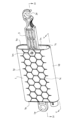
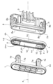
- FIG. 1 is an exploded perspective view of a damper device (first example) according to an embodiment of the present invention.
- FIG. 2 is an exploded perspective view of the first example.
- FIG. 3 is a perspective view of the first example.
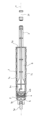
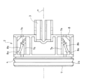
- FIG. 4 is a cross-sectional view taken along line IV-IV in FIG.
- FIG. 5 is a cross-sectional view taken along line VV in FIG.
- FIG. 6 is an enlarged cross-sectional view of the essential part of FIG. 4, in which the piston body is moved in a direction to reduce one space.
- FIG. 7 is an enlarged cross-sectional view of the essential part of FIG. 4, in which the piston body is moved in a direction to expand one space.
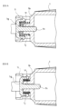
- 8A and 8B are enlarged cross-sectional views of the main parts of FIG. 5, where FIG.
- FIG. 8A shows the state of the orifice formation location when the piston body moves in a direction to reduce one of the spaces
- FIG. 8B shows the state of the orifice formation location when the piston body moves in a direction to expand one of the spaces.
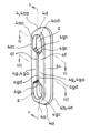
- FIG. 9 is a perspective view of the seal member constituting the first example.
- FIG. 10 is a cross-sectional view taken along line XX in FIG.
- FIG. 11 is a cross-sectional view taken along line XI-XI in FIG.
- FIG. 12 is a cross-sectional view taken along line XII-XII in FIG.
- FIG. 13 is a perspective view of the piston body and the seal member constituting the first example.
- FIG. 14 is a perspective view of the piston body in a state where the seal member is assembled with the piston body.
- FIG. 15 is a cross-sectional view taken along line XV-XV in FIG.
- FIG. 16 is a cross-sectional view taken along line XVI-XVI in FIG.
- FIG. 17 is a side view showing the configuration of a main part of a piston body constituting a damper device (second example) according to another embodiment of the present invention.
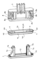
- FIG. 18 is an exploded perspective view of the piston body of the second embodiment.
- FIG. 19 is an exploded perspective view of the piston body of the second embodiment.
- FIG. 20 is a cross-sectional view showing the main part of the second example.
- the damper device generates a braking force on the movement or relative movement of the piston body 2 that constitutes it, and is typically combined with an article that has a movable part or the like (not shown) that is to be braked, and is used to apply the braking force to the movement of the object to be braked, to make the movement of the object to be braked slow, luxurious, moderate, or not sudden.
- the damper device is composed of a piston body 2 equipped with a rod body 3, and a cylinder body 1 that houses the piston body 2.
- the damper device is combined with an article equipped with the object to be braked by directly or indirectly connecting one of the rod body 3 and the cylinder body 1 to the object to be braked, and directly or indirectly connecting the other to a location that movably supports the object to be braked.
- the cylinder body 1 has a cylindrical shape with one end 1a open and the other end 1b closed.
- the cylinder body 1 may have a configuration in which both ends are open and one end is closed by a separate part.
- Such a cylinder body 1 has a flattened cylindrical shape with a significantly reduced thickness. More specifically, the cylinder body 1 has two wide side portions 1c and two narrow side portions 1d.
- the left and right narrow side portions 1d are curved so that the central axis x is on the inside of the curve, and the cross-sectional inner shape of the cylinder body 1 is an ellipse (a shape consisting of two parallel lines of equal length and two semicircles).
- a connection portion 1e for the above-mentioned linkage is formed on the outside of the other closed end 1b of the cylinder body 1.
- an orifice 1f is formed in the closed other end 1b of the cylinder body 1.
- a braking force adjustment member 1g with a shaft 1h movably inserted into the orifice 1f is held by a holding portion 1i formed on the outside of the other end 1b of the cylinder body 1.
- the symbol 1j denotes a coil spring that constantly biases the braking force adjustment member 1g in a direction that reduces the amount of penetration of the shaft 1h of the braking force adjustment member 1g into the orifice 1f.
- the rod body 3 is formed with an elongated hole 3a aligned with the moving direction of the piston body 2.
- a pin 1m is inserted through a through hole 1k formed in a pair of wide side surface portions 1c near the open one end 2a of the cylinder body 1 and the elongated hole 3a, thereby maintaining the combined state of the cylinder body 1 and the piston body 2 and guiding the movement of the piston body 2.
- the sealing member 4 which is to be combined with the piston body 2 and will be described later, is housed within the cylinder body 1 with the lip portion 4b, which will be described later, elastically deformed, and the extended end 4e (see Figure 9) of this lip portion 4b is adapted to contact the inner wall 1n of the cylinder body 1 at any position around the central axis x.
- the seal member 4 divides the space within the cylinder body 1 into one space 5 near the closed other end 2b and another space 6 near the open one end 2a.
- the movement of fluid from the one-side space 5 to the other-side space 6 is also allowed through the gap c created between the base portion 4a of the seal member 4 described below and the first retaining portion 2a of the piston body 2 described below, and the passage f provided at the location forming the second retaining portion 2b of the piston body 2 described below.
- the rod body 3 includes a rod main body 3b and a rod head portion 3c which is integrated with the inner end of the rod main body 3b located within the cylinder body 1.
- the rod head 3c has an inner portion 3d and an outer portion 3e, whose cross-sectional outer shape in a direction perpendicular to the central axis x is an ellipse following the inner cross-sectional shape of the cylinder body 1.
- One end of the rod main body 3b is integrated with the center of the outer portion 3e of the rod head 3c.
- a connecting portion 3f is formed at the outer end of the rod main body 3b located outside the cylinder body 1 for directly or indirectly connecting the rod main body 3b to a portion that movably supports an object to be braked.
- a fitted portion 3g for fitting with the fitting portion 2c of the piston body 2 is formed in the center of the inner portion 3d of the rod head portion 3c (see FIG. 5).
- the fitting portion 2c consists of a neck portion 2d and a fitting head 2e integrated into the center of the back portion opposite the side facing the first retaining portion 2a of the second retaining portion 2b described below of the piston body 2 via this neck portion 2d.
- the fitted portion 3g is composed of a notch 3h through which the neck portion 2d passes, and a fitting cavity 3i for the fitting head 2e formed between the inner portion 3d and the outer portion 3e.
- the piston body 2 is combined with a flat cylindrical seal member 4 as described below, and then the fitting head 2e is fitted into the fitting cavity 3i by utilizing the notch 3h of the rod head 3c, so that the piston body 2 and the rod body 3 are integrated.
- the piston body 2 includes a first retaining portion 2a, a second retaining portion 2b, and an intermediate portion 2f connecting the first retaining portion 2a and the second retaining portion 2b (see FIG. 2).
- the piston body 2 has a long portion facing the inner wall 1n of the cylinder body 1 at the wide side portion 1c, and a short portion facing the inner wall 1n of the cylinder body 1 at the narrow side portion 1d.
- the first retaining portion 2a and the second retaining portion 2b are each formed so that their outer contours are inscribed in a virtual ellipse (not shown) that follows the cross-sectional inner contour shape of the cylinder body 1.
- the intermediate portion 2f is formed around the entire circumference of the central axis x of the cylinder body 1 such that its outer contour is positioned closer to the central axis x than the outer contours of the first retaining portion 2a and the second retaining portion 2b, and the piston body 2 has a narrowed shape at the intermediate portion 2f.
- the first retaining portion 2a faces the base portion 4a of the sealing member 4, which will be described later, from a portion near the one-way space 5 of the piston body 2.
- the first retaining portion 2a has an outer contour shape that is complementary to the cross-sectional inner contour shape of the cylinder body 1.
- the first retaining portion 2a is plate-shaped with an elliptical contour shape.
- the first retaining portion 2a is configured to have a size between its outer edge and the inner wall 1n of the cylinder body 1 that allows the fluid (gas in this embodiment) to pass through at any position around the central axis x (see Figures 6 and 7).
- the intermediate portion 2f has a convex portion 2g that is substantially positioned on a virtual ellipse (not shown) that is imitated by the inner surface of the base portion 4a of the sealing member 4 described below, and a concave portion 2h that is positioned closer to the central axis x than the convex portion 2g (see FIG. 13).
- the short side portion of the intermediate portion 2f is the convex portion 2g
- the long side portion is the concave portion 2h.
- the second retaining portion 2b is located inside a lip portion 4b (described later) of the sealing member 4 and faces the base portion 4a from the portion near the other space 6 of the piston body 2.
- the outer contour of the second retaining portion 2b is located closer to the central axis x than the outer contour of the first retaining portion 2a around the entire circumference of the central axis x of the cylinder body 1.
- the longitudinal portion of the second retaining portion 2b is formed by a plurality of ribs 2i provided with gaps between adjacent ribs 2i, and the recessed portion 2h of the intermediate portion 2f and the gaps between these ribs 2i function as the passage f.
- the seal member 4 has elasticity and is formed in a circumferential shape surrounding the piston body 2.
- the seal member 4 is typically made of rubber or plastic having rubber-like elasticity.
- the seal member 4 has a flat ring shape and has two long sides 4c and two short sides 4d.
- the cross-sectional shape of the seal member 4 along the central axis x is substantially the same at any position around the central axis x except for the position where the restricting portion 4f described below is formed.
- the restricting portion 4f protrudes from the inside portion 4aa of the base portion 4a toward the central axis x within a certain range, as described below, and in Fig. 15, the inside portion 4aa of the base portion 4a at a position where the restricting portion 4f is not formed is shown by a dotted line.
- the portion closer to the central axis x than this dotted line functions as the restricting portion 4f.
- the seal member 4 has a base portion 4a positioned so as to face one space 5 in the cylinder body 1 divided by the piston body 2, and a lip portion 4b extending from the base portion 4a toward the other space 6 in the cylinder body 1, and the lip portion 4b is adapted to slide against the inner wall 1n of the cylinder body 1.
- the base portion 4a has outer and inner surfaces that are shaped like an ellipse similar to the ellipse that defines the inner cross-sectional shape of the cylinder body 1, but smaller than this ellipse. That is, the base portion 4a has two long portions 4c and two short portions 4d.
- the inner portion 4aa of the base portion 4a is configured to be positioned closer to the central axis x than the outer contour of the first retaining portion 2a and the outer contour of the second retaining portion 2b of the piston body 2, at any position around the central axis x. Therefore, the sealing member 4 is elastically deformed to allow the piston body 2 to pass through its inside from either the first retaining portion 2a or the second retaining portion 2b, and then, with the middle portion 2f of the piston body 2 positioned inside the sealing member 4, this elastic deformation is released, thereby fitting the sealing member 4 into the narrowed portion of the piston body 2, i.e., the middle portion 2f.
- the sealing member 4 in the two short portions 4d of the sealing member 4, the sealing member 4 is fitted into the piston body 2 with the inner portion 4aa of its base portion 4a in contact with the convex portion 2g of the middle portion 2f of the piston body 2.
- a gap y (see Figure 15) is formed between the inner portion 4aa of the base portion 4a of the sealing member 4 and the inner back wall of the recessed portion 2h of the intermediate portion 2f of the piston body 2 to allow the regulating portion described below to protrude.
- the outer portion 4ab of the base portion 4a is a surface facing the inner wall 1n of the cylinder body 1.
- the inner portion 4aa of the base portion 4a is a surface oriented substantially along the central axis x.
- the base portion 4a also has a front end surface 4ac that is substantially perpendicular to the central axis x and extends between the outer portion 4ab and the inner portion 4aa in the vicinity of the one space 5, and a rear end surface 4ad that is substantially perpendicular to the central axis x and extends between the outer portion 4ab and the inner portion 4aa in the vicinity of the other space 6.
- the distance between the front end face 4ac and the rear end face 4ad is slightly smaller than the distance between the first holding portion 2a and the second holding portion 2b.
- the seal member 4 fitted to the piston body 2 is held by the piston body 2 with the front end surface 4ac of the base portion 4a facing the first holding portion 2a and the rear end surface 4ad of the base portion 4a facing the second holding portion 2b (see Figures 6 and 7).
- the lip portion 4b is formed so as to protrude from a rear corner portion 4ae between an outer portion 4ab and a rear end face 4ad of the base portion 4a toward the other space 6, and is integral with the base portion 4a.
- the lip portion 4b is configured so that the cross-sectional shape in the direction along the central axis x is substantially the same at any position around the central axis x.
- the lip portion 4b has a lip outer surface that is continuous with the outer portion 4ab of the base portion 4a, and a lip inner surface whose rear end surface 4ad is between the lip portion 4b and the inner portion 4aa of the base portion 4a.
- the thickness of the lip portion 4b in the direction perpendicular to the central axis x is smaller than that of the base portion 4a, making it more susceptible to elastic deformation than the base portion 4a.
- the outer side 4ab of the base portion 4a is inclined in a direction in which the outer diameter of the base portion 4a increases as it approaches the rear corner portion 4ae.
- the lip portion 4b is formed so that the outer diameter of the seal member 4 gradually increases as it approaches the extending end 4e.
- the outer portion 4ab of the base portion 4a and the lip outer surface of the lip portion 4b are continuous with each other without creating any constriction between them. That is, the lip portion 4 b has a skirt shape extending from the rear corner portion 4 ae toward the other space 6 .
- the sealing member 4 has its outer diameter largest at the extending end 4e of the lip portion 4b, and does not contact the inner wall 1n of the cylinder body 1 at the base portion 4a, but contacts the inner wall 1n of the cylinder body 1 at the extending end 4e of the lip portion 4b or in its vicinity.
- the seal member 4 is provided with a restricting portion 4f between the base portion 4a constituting the two longitudinal portions 4c facing the wide side portion 1c of the cylinder body 1, which is formed so as to contact the first retaining portion 2a nearer the central axis x of the movement of the piston body 2 than the base portion 4a when the piston body 2 moves toward the one space 5, thereby maintaining the position of the longitudinal portion 4c of the seal member 4.
- the restricting portion 4f is formed by a protruding portion 4g formed on each of the two longitudinal portions 4c of the sealing member 4 and protruding toward the central axis x of movement of the piston body 2.
- the protruding portion 4g is in the form of a convex piece having a length and a width, i.e., the protruding portion 4g has a length that continues along the longitudinal direction of the longitudinal portion 4c and a width that protrudes from the inner portion 4aa of the base portion 4a toward the central axis x.
- the protruding portion 4g also has a first surface 4ga continuous with the front end surface 4ac of the base portion 4a, and a second surface 4gb continuous with the rear end surface 4ad of the base portion 4a.
- the protrusion portion 4g has a first surface 4ga facing the first retaining portion 2a and a second surface 4gb facing the second retaining portion 2b at a position closer to the central axis x than the base portion 4a.
- the protrusion portion 4g is formed near the inner portion 4aa of the base portion 4a that constitutes the long portion 4c, so that a gap z (see Figures 9 and 10) of approximately half the total length of the protrusion portion 4g is provided between one of the two short portions 4d and one end 4gc of the protrusion portion 4g directed toward this short portion 4d, and between the other of the two short portions 4d and the other end 4gc of the protrusion portion 4g directed toward this short portion 4d.
- a gap is formed between the tip end of the protruding portion 4g formed on one of the two longitudinal portions 4c, which is located near the central axis x, and the tip end of the protruding portion 4g formed on the other of the two longitudinal portions 4c, which is located near the central axis x, so that the recessed portion 2h of the intermediate portion 2f can be accommodated therein.
- one end 4gc and the other end 4gc of the protruding portion 4g are each inclined in a direction such that the length of the protruding portion 4g decreases as the end 4gc approaches the tip end 4gd of the protruding portion 4g.
- the restricting portion 4f can receive the force P2 acting on the base portion 4a when the force P1 acts on the lip portion 4b as described above by pressing the restricting portion 4f against the first holding portion 2a, thereby suppressing unexpected deformation of the longitudinal portion 4c of the seal member 4.
- the function of the restricting portion 4f allows the orientation of the longitudinal portion 4c of the seal member 4, which is easily deformed, to be stably maintained in a desired orientation throughout the entire process of the movement of the piston body 2 or the relative movement.
- the restricting portion 4f is formed on the long portion 4c of the seal member 4, but not on the short portion 4d.
- the short portion 4d of the seal member 4 is used as the deformation center to widen the distance between the two long portions 4c of the seal member 4, making it easier to receive the piston body 2 between them, and facilitating the fitting operation.
- the second surface 4gb of the protrusion portion 4g is configured to be inclined so that the thickness of the protrusion portion 4g gradually decreases as it approaches the tip portion 4gd of the protrusion portion 4g, as shown in Figure 10.
- the protrusion portion 4g has the first surface 4ga as a surface perpendicular to the central axis x, the tip portion 4gd which is the protruding end as a surface oriented along the central axis x, and the second surface 4gb is inclined as described above over the entire length of the protrusion portion 4g.
- (Second Example) 17 to 20 show a second example in which the piston body 2 is configured by combining a first portion 7 having a first holding portion 2a and a second portion 8 having a second holding portion 2b (see FIG. 19) so as to sandwich the seal member 4 therebetween.
- the second portion 8 is integrated with the inner end of the rod body 3.
- the remaining configuration of this second example is the same or substantially the same as that of the first example, so a description thereof will be omitted.
- the first portion 7 is composed of a plate having an elliptical outline that is complementary to the inner cross-sectional shape of the flattened cylindrical body 1 in a direction perpendicular to the central axis x.
- the second portion 8 is formed by a surface portion located in the vicinity of the one space 5 in the rod head portion. This surface portion also has an elliptical outline that is complementary to the inner cross-sectional shape of the cylinder body 1.
- the first portion 7 is provided with legs 7a that protrude toward the other space 6 from a surface portion facing the other space 6.
- the legs 7a are provided on both sides of the first portion 7 at a position approximately midway in the longitudinal direction.
- the second portion 8 has receiving portions 8a formed on both sides of the middle position in the longitudinal direction thereof, for receiving the leg bodies 7a.
- a claw portion 7b is formed at the tip of the leg body 7a
- an elastic piece 8b is formed inside the receiving portion 8a.
- the insertion of the leg body 7a into the receiving portion 8a is allowed by the elastic deformation of the elastic piece 8b, and when the leg body 7a is fully inserted into the receiving portion 8a, the elastic return of the elastic piece 8b causes the tip of the elastic piece 8b to engage with the claw portion 7b of the leg body 7a.
- the claw portion 7b is formed on the opposite side of the leg 7a from the central axis x.
- the elastic piece 8b has a base near the entrance of the receiving portion 8a and extends so that the distance from the central axis x gradually decreases as it approaches the back of the receiving portion 8a.
- the elastic piece 8b elastically returns in a direction approaching the central axis x, and the elastic piece 8b enters between the entrance of the receiving portion 8a and the claw portion 7b, preventing the leg 7a from slipping out of the receiving portion 8a.
- the seal member 4 constituting the second example has a configuration in which a bridge portion 4h serving as a restricting portion 4f is formed between two longitudinal portions 4c.
- the bridge portion 4h has a width spanning between the inner portions 4aa of the base portions 4a constituting the two longitudinal portions 4c, and is bridged between the two base portions 4a.
- the installation portion 4h has a length in a direction parallel to the length of the longitudinal portion 4c of the sealing member 4, and a gap z is formed between one end portion 4ha directed toward one of the two short portions 4d of the sealing member 4 in the installation portion 4h and this one short portion 4d, and between the other end portion 4ha directed toward the other of the two short portions 4d of the sealing member 4 in the installation portion 4h and this other short portion 4d, thereby blocking the remaining area between the two base portions 4a.
- the leg 7a can be introduced into the receiving portion 8a by utilizing the gap z between the bridge portion 4h and the short portion 4d, thereby making it possible to combine the first part 7 having the first retaining portion 2a and the second part 8 having the second retaining portion 2b by clamping the sealing member 4 between them.
- a groove 9 and a protrusion 10 are formed in the first retaining portion 2a and the seal member 4, respectively.
- Each of the grooves 9 and the protrusions 10 is formed so as to go around the central axis x and to follow the elliptical contours of the first portion 7 and the second portion 8.
- the first retaining portion 2a has a protrusion 10 on the inside, and a groove 9 adjacent to the protrusion 10 on the outside.
- the seal member 4 has a groove 9 on the inside at the front end surface 4ac of the base portion 4a, and a protrusion 10 adjacent to the groove 9 on the outside.
Landscapes
- Engineering & Computer Science (AREA)
- General Engineering & Computer Science (AREA)
- Mechanical Engineering (AREA)
- Fluid-Damping Devices (AREA)
- Sealing With Elastic Sealing Lips (AREA)
Abstract
Description
前記シール部材は、弾性を有し、前記ピストン体を取り巻く周回状をなすと共に、前記ピストン体によって区分される前記シリンダー体内の空間の一方の近傍に位置するベース部と、このベース部から前記シリンダー体内の他方空間に向かって延び出すリップ部とを有し、前記シール部材は、前記リップ部において前記シリンダー体の内壁に摺接するように構成されており、
前記ピストン体は、前記一方空間の近傍から前記シール部材の前記ベース部に向き合う前記シール部材の第一保持部と、前記シール部材の前記リップ部の内側に位置して前記他方空間の近傍から前記ベース部に向き合う前記シール部材の第二保持部とを備えており、
前記シール部材における前記シリンダー体の前記幅広側面部に向き合う二箇所の長手部分を構成する前記ベース部の間に、前記ピストン体が前記一方空間に向かって移動するときに前記ベース部よりも前記ピストン体の移動中心軸線の近傍において前記第一保持部に接するように形成されて前記シール部材の前記長手部分の姿勢を維持する規制部を備えさせてなる、ものとした。
シール部材の長手部分に前記規制部を設けてない場合、前記のようにベース部に作用される力によって、長手部分は変形し易く、長手部分の変形が制御できないと前記制動力も制御できないこととなる。
これに対し、前記構成によれば、前記規制部により、前記のようにリップ部に力が作用されたときに前記ベース部に作用される力を、規制部を第一保持部に押し当てることで受けさせることができる。これにより、シール部材の長手部分の予期できない変形を抑制することができる。
この場合、さらに、前記ピストン体の前記第一部分における前記第一保持部及び前記シール部材の前記ベース部のいずれか一方に溝を形成すると共に、これらの他方に前記溝に納まるリブを形成するようにすることが、この発明の態様の一つとされる。
より具体的には、かかるシリンダー体1は、二箇所の幅広側面部1cと二箇所の幅狭側面部1dとを備えている。シリンダー体1をその中心軸線x(図4、図5参照/すなわち、ピストン体2の移動中心軸線)に直交する向きに断面にした状態において、左右の幅狭側面部1dは、前記中心軸線xを湾曲内側とするように湾曲されており、シリンダー体1の断面内郭形状は、長円状(二つの等しい長さの平行線と二つの半円形からなる形状)となっている。シリンダー体1の閉された他端1bの外側には、前記連係のための接続部1eが形成されている。
ピストン体2に組み合わされる後述のシール部材4は、後述のリップ部4bを弾性変形させた状態でシリンダー体1内に納められ、このリップ部4bの延び出し端4e(図9参照)を前記中心軸線xを巡るいずれの位置においてもシリンダー体1の内壁1nに接しさせるようになっている。
このシール部材4によって、シリンダー体1内の空間は、閉塞された他端2b寄りの一方空間5と、開放された一端2a寄りの他方空間6に区分される。
ロッド頭部3cは、前記中心軸線xに直交する向きの断面外郭形状を、前記シリンダー体1の断面内郭形状に倣った長円状とする内側部分3d及び外側部分3eを有する。
ロッド主体3bは、その一端をロッド頭部3cの外側部分3eの中央に一体化させている。また、ロッド主体3bにおけるシリンダー体1外に位置される外端には、制動対象を移動可能に支持する箇所に直接又は間接に連係させるための接続部3fが形成されている。
図示の例では、嵌合部2cは、頸部2dとこの頸部2dを介してピストン体2の後述の第二保持部2bの第一保持部2aに向き合う側と反対の背面部の中央に一体化された嵌合頭部2eとからなる。
一方、被嵌合部3gは、前記頸部2dを通過させる割欠き3hと、内側部分3dと外側部分3eとの間に形成された嵌合頭部2eのはめ込み空所3iとからなる。図1乃至図16に示される第一例では、ピストン体2に後述のように扁平筒状をなすシール部材4を組み合わせた状態から、ロッド頭部3cの割欠き3hを利用して嵌合頭部2eをはめ込み空所3iに納めることで、ピストン体2とロッド体3とが一体化されるようになっている。
ピストン体2は、シリンダー体1の幅広側面部1cにおいてその内壁1nに向き合う長手部分と、シリンダー体1の幅狭側面部1dにおいてその内壁1nに向き合う短手部分とを持つ。
中間部2fは、シリンダー体1の中心軸線xを巡る全周に亘り、その外郭を第一保持部2a及び第二保持部2bの外郭よりも前記中心軸線x寄りに位置させるように形成されており、ピストン体2は、中間部2fにおいてくびれた形態となっている。
また、シール部材4は、扁平なリング状を呈し、二箇所の長手部分4cと二箇所の短手部分4dとを有する。
シール部材4における、前記中心軸線xに沿った向きでの断面形状は、後述の規制部4fの形成箇所以外の箇所では、前記中心軸線xを巡るいずれの位置においても実質的に同一の形状となっている。この規制部4fは、後述のように一定の範囲でベース部4aの内側部4aaから中心軸線xに向かって突き出しており、図15においては、規制部4fの形成されていない位置でのベース部の4a内側部4aaを点線で示している。この点線より中心軸線x寄りの部分が規制部4fとして機能する。
すなわち、ベース部4aは、二箇所の長手部分4cと二箇所の短手部分4dとを有する。
したがって、シール部材4は、その内側に第一保持部2a及び第二保持部2bのいずれか一方からピストン体2を通過させるように弾性変形された後、シール部材4の内側にピストン体2の中間部2fが位置された状態でこの弾性変形を解くことにより、ピストン体2のくびれ部分、つまり中間部2fに嵌められる。
図示の例では、シール部材4の二箇所の短手部分4dにおいては、シール部材4は、そのベース部4aの内側部4aaを、ピストン体2の中間部2fの凸部分2gに接しさせた状態で、ピストン体2に嵌められている。
一方、シール部材4の二箇所の長手部分4cにおいては、シール部材4のベース部4aの内側部4aaと、ピストン体2の中間部2fの凹部分2hの内奥壁との間には、後述の規制部が突き出ることを許すための間隔y(図15参照)が形成されるようになっている。
この前端面4acと後端面4adとの間の距離は、第一保持部2aと第二保持部2bとの間の距離よりも僅かに小さくなっている。
前記のように、ピストン体2に嵌められたシール部材4は、ベース部4aの前端面4acを第一保持部2aに向き合わせ、ベース部4aの後端面4adを第二保持部2bに向き合わせて、ピストン体2に保持される(図6、図7参照)。
リップ部4bは、ベース部4aの外側部4abに連続するリップ外面と、ベース部4aの内側部4aaとの間をベース部4aの後端面4adとするリップ内面とを有し、前記中心軸線xに直交する向きの厚さをベース部4aより小さくしてベース部4aよりも弾性変形し易い構造となっている。
ベース部4aの外側部4abとリップ部4bのリップ外面とは、両者間にくびれなどを作ることなく、連続している。
すなわち、リップ部4bは、前記後隅部4aeから他方空間6に向かって延びるスカート状を呈している。
シール部材4は、リップ部4bの延び出し端4eで最も外径を大きくし、シリンダー体1の内壁1nに対してはベース部4aでは接せず、リップ部4bの延び出し端4e又はその近傍においてシリンダー体1の内壁1nに接するようになっている。
また、張り出し部4gは、ベース部4aの前端面4acに連続した第一面4gaと、ベース部4aの後端面4adに連続した第二面4gbとを備えている。
これによって、張り出し部4gは、前記ベース部4aよりも中心軸線x寄りの位置において、前記第一保持部2aに向き合う第一面4gaと、前記第二保持部2bに向き合う第二面4gbとを有している。
また、張り出し部4gは、二箇所の短手部分4dの一方とこの短手部分4dに向けられた張り出し部4gの一端部4gcとの間、および、二箇所の短手部分4dの他方とこの短手部分4dに向けられた張り出し部4gの他端部4gcとの間にそれぞれ、張り出し部4gの全長の半分程度の距離の間隔z(図9及び図10参照)を開けるようにして、長手部分4cを構成するベース部4aの内側部4aaの近傍に形成されている。
また、二箇所の長手部分4cの一方に形成された張り出し部4gにおける前記中心軸線xの近傍に位置される先端部と、二箇所の長手部分4cの他方に形成された張り出し部4gにおける前記中心軸線xの近傍に位置される先端部との間には、中間部2fの凹部分2hが納まる間隔が形成されるようになっている。
なお、図示の例では、前記張り出し部4gの一端部4gc及び他端部4gcは、それぞれ、張り出し部4gの先端部4gdに近づくに連れて、張り出し部4gの長さを減じる向きに傾斜している。
このとき、シール部材4のベース部4aには、前記リップ部4bに作用される力P1によってシリンダー体1の幅広側面部1cの内壁1nに近づく向きの力P2が作用される。
シール部材4の長手部分4cに前記規制部4fを設けてない場合、前記のように、ベース部4aに作用される力P2によって、長手部分4cは変形し易く、長手部分4cの変形が制御できないと、前記制動力も制御できないこととなる。
これに対し、この実施の形態にあっては、前記規制部4fにより、前記のようにリップ部4bに力P1が作用されたときに前記ベース部4aに作用される力P2を、規制部4fを第一保持部2aに押し当てることで受けさせることができ、これにより、シール部材4の長手部分4cの予期できない変形を抑制することができる。すなわち、かかる規制部4fの機能により、変形しやすいシール部材4の長手部分4cの姿勢は、ピストン体2の移動又は相対的な移動の全過程において所期の姿勢に安定的に維持される。
図示の例では、張り出し部4gは、前記第一面4gaを前記中心軸線xに直交する面部とし、その突き出し端となる先端部4gdを前記中心軸線xに沿う向きの面部とすると共に、前記第二面4gbを張り出し部4gの全長に亘って前記のように傾斜させた形態となっている。
この第二面4gbの傾斜により、ピストン体2の第二保持部2bの近傍部分からピストン体2の中間部2fをシール部材4を弾性変形させながら、このシール部材4内にピストン体2の中間部2fを受け入れさせるようにして行うシール部材4のピストン体2に対する前記嵌め付け作業において、張り出し部4gが第二保持部2bを乗り越えた後のシール部材4の弾性復帰によって、張り出し部4gを第一保持部2aと第二保持部2bとの間にスムースに入り込ませることができるようになっている。
図17乃至図20は、前記ピストン体2を、第一保持部2aを備えた第一部分7と、第二保持部2b(図19参照)を備えた第二部分8とを、両者間でシール部材4を挟持するようにして組み合わせた構成としてなる、第二例を示している。第二部分8は、ロッド体3の内端に一体化されている。
この第二例のその余の構成は、前記第一例と同一又は実質的に同一であるので、その説明は省略する。
第二部分8は、ロッド頭部における一方空間5の近傍に位置される面部によって構成されている。この面部も、前記シリンダー体1の断面内郭形状と相補となる長円状の輪郭を備えている。
図示の例では、第一部分7には、他方空間6を向く面部から他方空間6に向けて突き出す脚体7aが備えられている。脚体7aは、第一部分7の長軸方向中程の位置を挟んだ両側にそれぞれ設けられている。
また、第二部分8には、その長軸方向中程の位置を挟んだ両側にそれぞれ、前記脚体7aを受け入れる受入部8aが形成されている。
また、前記脚体7aの先端には爪部7bが形成され、前記受入部8aの内部には、弾性片8bが形成されており、受入部8aへの脚体7aの差し込みは、弾性片8bの弾性変形により許容されると共に、受入部8aに脚体7aを差し込みきった位置での弾性片8bの弾性復帰により、脚体7aの爪部7bに弾性片8bの先端が係合されるようになっている。
図示の例では、爪部7bは、脚体7aにおける前記中心軸線xとは反対側に形成されている。一方、弾性片8bは、受入部8aの入り口の近傍に基部を持ち、受入部8aの奥に向かうにつれて中心軸線xとの距離を漸減させるように延びた形態となっている。受入部8aへ脚体7aを導入すると、爪部7bが弾性片8bに接して中心軸線xから離れる向きに弾性片8bが変形されて、受入部8aへの脚体7aの導入が許容される。受入部8aに脚体7aを差し込みきると、弾性片8bが、中心軸線xに近づく向きに弾性復帰し、弾性片8bが、受入部8aの入り口と爪部7bとの間に入り込み、受入部8aからの脚体7aの抜け出しが阻止される。
架設部4hは、前記二箇所の長手部分4cを構成するベース部4aの内側部4aa間に亘る幅を持ち、二箇所のベース部4a間に架設されている。
また、架設部4hは、シール部材4の長手部分4cの長さに沿う向きの長さを持ち、架設部4hにおけるシール部材4の二箇所の短手部分4dの一方に向けられた一端部4haとこの一方の短手部分4dとの間、および、架設部4hにおけるシール部材4の二箇所の短手部分4dの他方に向けられた他端部4haとこの他方の短手部分4dとの間にそれぞれ間隔zを形成させた状態で、二箇所ベース部4a間のその余の領域を塞いだ形態となっている。
図示の例では、架設部4hと短手部分4dとの間の間隔zを利用して、前記脚体7aが、受入部8a部に導入可能となっており、これにより、前記第一保持部2aを備えた第一部分7と、前記第二保持部2bを備えた第二部分8とを、両者間で前記シール部材4を挟持するようにして組み合わせることが可能となっている。
図示の例では、第一保持部2aとシール部材4とにそれぞれ、溝9と突条10とを形成させている。いずれの溝9及び突条10も、前記中心軸線xを周回するように形成されており、前記第一部分7及び前記第二部分8の長円輪郭に沿うように形成されている。
第一保持部2aでは、内側に突条10があり、これに隣接した外側を溝9とするようになっている。シール部材4は、ベース部4aの前端面4acにおいて、内側に溝9があり、これに隣接した外側を突条10とするようになっている。そして、前記のようにシール部材4を挟んで第一部分7と第二部分8とを組み合わせた状態において、第一保持部2aの突条10が、シール部材4のベース部4aの溝9に入り込み、かつ、第一保持部2aの溝9にシール部材4のベース部4aの突条10が、入り込むようになっている。
1c 幅広側面部
2 ピストン体
2a 第一保持部
2b 第二保持部
4 シール部材
4a ベース部
4b リップ部
4c 長手部分
4f 規制部
x 中心軸線
なお、2023年6月5日に出願された日本国特許出願第2023-092361号の明細書、特許請求の範囲、図面及び要約書の全内容をここに引用し、本発明の明細書の開示として、取り入れるものである。
Claims (6)
- 一対の幅広側面部と一対の幅狭側面部とを有する扁平筒状のシリンダー体と、前記シリンダー体内に移動可能に納められたピストン体と、前記シリンダー体と前記ピストン体との間をシールするシール部材とを備え、前記ピストン体の移動又は相対的な移動により制動力を生じさせるダンパー装置であって、
前記シール部材は、弾性を有し、前記ピストン体を取り巻く周回状をなすと共に、前記ピストン体によって区分される前記シリンダー体内の空間の一方の近傍に位置するベース部と、このベース部から前記シリンダー体内の他方空間に向かって延び出すリップ部とを有し、前記リップ部において前記シリンダー体の内壁に摺接するようになっており、
前記ピストン体は、前記一方空間の近傍から前記シール部材の前記ベース部に向き合う前記シール部材の第一保持部と、前記シール部材の前記リップ部の内側に位置して前記他方空間の近傍から前記ベース部に向き合う前記シール部材の第二保持部とを備えており、
前記シール部材における前記シリンダー体の前記幅広側面部に向き合う二箇所の長手部分を構成する前記ベース部の間に、前記ピストン体が前記一方空間に向かって移動するときに前記ベース部よりも前記ピストン体の移動中心軸線の近傍において前記第一保持部に接するように形成されて前記シール部材の前記長手部分の姿勢を維持する規制部を備えさせてなる、ダンパー装置。 - 前記シール部材の二箇所の前記長手部分にそれぞれ、前記ピストン体の前記移動中心軸線に向かって突き出す前記規制部となる張り出し部を形成させてなる、請求項1に記載のダンパー装置。
- 前記張り出し部は、前記第一保持部に向き合う第一面と、前記第二保持部に向き合う第二面とを有すると共に、前記第二面を、前記張り出し部の先端部に近づくに連れて前記張り出し部の厚さを漸減させるように傾斜させてなる、請求項1に記載のダンパー装置。
- 前記シール部材の二箇所の前記長手部分間に前記規制部となる架設部を形成させてなる、請求項1に記載のダンパー装置。
- 前記ピストン体を、前記第一保持部を備えた第一部分と、前記第二保持部を備えた第二部分とを、両者間で前記シール部材を挟持するようにして組み合わせた構成としてなる、請求項1に記載のダンパー装置。
- 前記ピストン体の前記第一部分における前記第一保持部及び前記シール部材の前記ベース部のいずれか一方に溝が形成されていると共に、これらの他方に前記溝に納まるリブを形成させてなる、請求項5に記載のダンパー装置。
Priority Applications (3)
| Application Number | Priority Date | Filing Date | Title |
|---|---|---|---|
| CN202480032588.0A CN121127688A (zh) | 2023-06-05 | 2024-04-24 | 阻尼装置 |
| KR1020257034882A KR20250168392A (ko) | 2023-06-05 | 2024-04-24 | 댐퍼 장치 |
| MX2025013758A MX2025013758A (es) | 2023-06-05 | 2025-11-18 | Dispositivo amortiguador |
Applications Claiming Priority (2)
| Application Number | Priority Date | Filing Date | Title |
|---|---|---|---|
| JP2023092361A JP7791639B2 (ja) | 2023-06-05 | 2023-06-05 | ダンパー装置 |
| JP2023-092361 | 2023-06-05 |
Publications (1)
| Publication Number | Publication Date |
|---|---|
| WO2024252817A1 true WO2024252817A1 (ja) | 2024-12-12 |
Family
ID=93795408
Family Applications (1)
| Application Number | Title | Priority Date | Filing Date |
|---|---|---|---|
| PCT/JP2024/016082 Ceased WO2024252817A1 (ja) | 2023-06-05 | 2024-04-24 | ダンパー装置 |
Country Status (5)
| Country | Link |
|---|---|
| JP (1) | JP7791639B2 (ja) |
| KR (1) | KR20250168392A (ja) |
| CN (1) | CN121127688A (ja) |
| MX (1) | MX2025013758A (ja) |
| WO (1) | WO2024252817A1 (ja) |
Citations (2)
| Publication number | Priority date | Publication date | Assignee | Title |
|---|---|---|---|---|
| WO2018079064A1 (ja) * | 2016-10-26 | 2018-05-03 | 株式会社ニフコ | ダンパー |
| JP2022123993A (ja) * | 2021-02-15 | 2022-08-25 | 株式会社ニフコ | ダンパー装置 |
-
2023
- 2023-06-05 JP JP2023092361A patent/JP7791639B2/ja active Active
-
2024
- 2024-04-24 KR KR1020257034882A patent/KR20250168392A/ko active Pending
- 2024-04-24 CN CN202480032588.0A patent/CN121127688A/zh active Pending
- 2024-04-24 WO PCT/JP2024/016082 patent/WO2024252817A1/ja not_active Ceased
-
2025
- 2025-11-18 MX MX2025013758A patent/MX2025013758A/es unknown
Patent Citations (2)
| Publication number | Priority date | Publication date | Assignee | Title |
|---|---|---|---|---|
| WO2018079064A1 (ja) * | 2016-10-26 | 2018-05-03 | 株式会社ニフコ | ダンパー |
| JP2022123993A (ja) * | 2021-02-15 | 2022-08-25 | 株式会社ニフコ | ダンパー装置 |
Also Published As
| Publication number | Publication date |
|---|---|
| JP2024174504A (ja) | 2024-12-17 |
| KR20250168392A (ko) | 2025-12-02 |
| CN121127688A (zh) | 2025-12-12 |
| MX2025013758A (es) | 2026-01-07 |
| JP7791639B2 (ja) | 2025-12-24 |
Similar Documents
| Publication | Publication Date | Title |
|---|---|---|
| US8453810B2 (en) | Damper device | |
| KR101647562B1 (ko) | 댐퍼 | |
| JP2010071406A (ja) | シリンダ装置 | |
| JP7481993B2 (ja) | ダンパー装置 | |
| CN109296690B (zh) | 阻尼器 | |
| JPWO2019188807A1 (ja) | ダンパー | |
| US10883557B2 (en) | Damper | |
| JP7791639B2 (ja) | ダンパー装置 | |
| US20220260128A1 (en) | Damper device | |
| US6668862B2 (en) | Fluid bearing mechanism | |
| WO2022181353A1 (ja) | ダンパー装置 | |
| ITVR970006A1 (it) | Unita' di tenuta anulare e procedimento per la sua fabbricazione | |
| JP6479234B2 (ja) | ダンパー | |
| JP2563216Y2 (ja) | 空気圧シリンダのシール装置 | |
| JPS61103677U (ja) | ||
| JP3307865B2 (ja) | ロッドレスシリンダのクッション装置 | |
| JPH0684041U (ja) | ダンパ | |
| JPH1044967A (ja) | マスタシリンダ | |
| JPH03117144U (ja) |
Legal Events
| Date | Code | Title | Description |
|---|---|---|---|
| 121 | Ep: the epo has been informed by wipo that ep was designated in this application |
Ref document number: 24819054 Country of ref document: EP Kind code of ref document: A1 |
|
| ENP | Entry into the national phase |
Ref document number: 1020257034882 Country of ref document: KR Free format text: ST27 STATUS EVENT CODE: A-0-1-A10-A15-NAP-PA0105 (AS PROVIDED BY THE NATIONAL OFFICE) |
|
| WWE | Wipo information: entry into national phase |
Ref document number: KR1020257034882 Country of ref document: KR Ref document number: 1020257034882 Country of ref document: KR |
|
| WWE | Wipo information: entry into national phase |
Ref document number: MX/A/2025/013758 Country of ref document: MX |
|
| WWP | Wipo information: published in national office |
Ref document number: 1020257034882 Country of ref document: KR |
|
| NENP | Non-entry into the national phase |
Ref country code: DE |
|
| WWP | Wipo information: published in national office |
Ref document number: MX/A/2025/013758 Country of ref document: MX |