WO2024252764A1 - コントローラ - Google Patents
コントローラ Download PDFInfo
- Publication number
- WO2024252764A1 WO2024252764A1 PCT/JP2024/012545 JP2024012545W WO2024252764A1 WO 2024252764 A1 WO2024252764 A1 WO 2024252764A1 JP 2024012545 W JP2024012545 W JP 2024012545W WO 2024252764 A1 WO2024252764 A1 WO 2024252764A1
- Authority
- WO
- WIPO (PCT)
- Prior art keywords
- stick
- controller
- braking
- analog
- pressing
- Prior art date
- Legal status (The legal status is an assumption and is not a legal conclusion. Google has not performed a legal analysis and makes no representation as to the accuracy of the status listed.)
- Pending
Links
Images


Classifications
-
- A—HUMAN NECESSITIES
- A63—SPORTS; GAMES; AMUSEMENTS
- A63F—CARD, BOARD, OR ROULETTE GAMES; INDOOR GAMES USING SMALL MOVING PLAYING BODIES; VIDEO GAMES; GAMES NOT OTHERWISE PROVIDED FOR
- A63F13/00—Video games, i.e. games using an electronically generated display having two or more dimensions
- A63F13/20—Input arrangements for video game devices
- A63F13/24—Constructional details thereof, e.g. game controllers with detachable joystick handles
-
- G—PHYSICS
- G06—COMPUTING OR CALCULATING; COUNTING
- G06F—ELECTRIC DIGITAL DATA PROCESSING
- G06F3/00—Input arrangements for transferring data to be processed into a form capable of being handled by the computer; Output arrangements for transferring data from processing unit to output unit, e.g. interface arrangements
- G06F3/01—Input arrangements or combined input and output arrangements for interaction between user and computer
- G06F3/03—Arrangements for converting the position or the displacement of a member into a coded form
- G06F3/033—Pointing devices displaced or positioned by the user, e.g. mice, trackballs, pens or joysticks; Accessories therefor
- G06F3/0338—Pointing devices displaced or positioned by the user, e.g. mice, trackballs, pens or joysticks; Accessories therefor with detection of limited linear or angular displacement of an operating part of the device from a neutral position, e.g. isotonic or isometric joysticks
Definitions
- the present invention relates to a controller equipped with an analog stick.
- An analog stick is a control device that outputs an analog value according to the direction in which the stick is tilted and the angle at which the stick is tilted (tilt angle) when the operator uses his or her finger to tilt a vertically-positioned stick (operating lever) in any direction.
- Analog sticks often have an auto-centering mechanism that returns the stick to a neutral position (vertical) by the restoring force of a spring, for example, when you release the pressure on the stick with your finger.
- the auto-centering mechanism has the following problems. 1)
- the spring's restoring force is not enough as a clue for operation
- the spring's restoring force is not only for returning the stick to the neutral position, but also serves as a clue for the operator when operating the analog stick. For example, when the operator stops the analog stick halfway or tilts it slowly, the operator can easily operate the analog stick because they can feel the spring's restoring force with their fingers.
- the spring's restoring force is set to be weak so that even players with weak muscles can easily operate the analog stick, the majority of players find the spring's restoring force insufficient to provide a sufficient cue for operation.
- the operator In order to maintain a constant tilt angle of the analog stick, the operator needs to continue to apply a force to the analog stick with his/her finger that balances the restoring force of the spring.
- human muscles are not structured to perform the above-mentioned operations, so the analog stick may wobble or the operator's fingers may tremble, making it difficult for the operator to maintain a constant tilt angle of the analog stick.
- the analog value remains at 0 in the dead zone, and the character or shooting aim does not move. Also, if the operator tilts the analog stick at a constant speed around the neutral position with the intention of changing the analog value output from the analog stick at a constant rate, the analog value will be 0 in the dead zone, and so the analog value will become a value not intended by the operator.
- Analog stick return operation is not reflected in the game
- the analog stick When an operator returns the analog stick from a position tilted at a certain tilt angle to a neutral position, the analog stick outputs the same analog value when the operator releases his/her finger from the analog stick at a position tilted at the same tilt angle as the tilt angle.
- a controller for a game device when an operator returns the analog stick, that analog value needs to be reflected in the game.
- the analog value output from the analog stick when the operator simply releases his/her finger is due to the operation of the auto-centering mechanism, so there is no need to reflect that analog value in the game.
- Speed control is a method of converting an analog value according to the tilt angle of the stick into the movement speed of the character or the like, and the greater the tilt angle of the stick, the faster the character or the like moves.
- a disadvantage of using speed control occurs when the operator returns the analog stick to the neutral position with the intention of moving a character in the opposite direction from its previous movement. For example, if the operator tilts the analog stick to the left at a certain angle to move a character to the left in the game space, but the character goes too far to the left of the desired position, the operator returns the analog stick to the neutral position with the intention of moving it slightly to the right.
- the speed control only slows down the character's movement speed without changing the direction of movement, and the character continues to move to the left. In other words, the operator's intention of changing the direction of movement of the character is not realized.
- conventional controllers for game devices include those that allow the sensitivity of the analog value of the analog stick to be adjusted, such as those shown below.
- the flat surface of the controller described in Patent Document 1 is provided with a left analog stick operated by the thumb of the operator's left hand, a right analog stick operated by the thumb of the operator's right hand, a cross key, and the like. Meanwhile, a sensitivity adjustment button is provided on the bottom surface of the controller in a position that can be operated by the middle finger of the operator's left hand. In addition, a sensitivity switching dial is provided on the side of the controller, which can change the sensitivity of the analog values of the left analog stick and right analog stick.
- the operator tilts the right analog stick in the direction in which he or she wants the reticle to be superimposed on the target, and by changing the analog value of the right analog stick, the operator can move the reticle on the display screen so that it is superimposed on the target.
- the operator In this state, if the operator wishes to reduce the sensitivity of the aiming for shooting, the operator operates the right analog stick and then presses the sensitivity adjustment button with the middle finger of the left hand. This reduces the sensitivity of the analog value of the right analog stick, allowing for fine adjustment of the aiming for shooting.
- JP 2014-61225 A (paragraphs 0033, 0049 to 0054, and Figures 1 to 5)
- Patent Document 1 cannot solve the following problems 1) to 4) caused by the auto-centering mechanism of the analog stick. 1) The spring's restoring force is not strong enough to provide a clue for operation. 2) It is difficult to maintain a constant tilt angle of the analog stick. 3) The tilt of the analog stick near the neutral position is not reflected in the game. 4) The return operation of the analog stick is not reflected in the game.
- the objective of the present invention is to provide a controller that provides sufficient operational clues, can maintain a constant tilt angle of the analog stick, and enables tilting and returning of the analog stick near the neutral position to be reflected in games, etc.
- a controller includes an analog stick that outputs an analog value corresponding to the direction in which the stick is tilted and the angle at which the stick is tilted, a braked member attached to either the stick, a cap attached to one end of the stick, or a driven part that rotates in response to tilting of the stick, and a braking part that brakes the analog stick by suppressing the movement of the braked member.
- the controller of the present invention includes an analog stick that outputs an analog value corresponding to the direction in which the stick is tilted and the angle at which the stick is tilted, a pressure receiving member attached to either the stick, a cap attached to one end of the stick, or a follower that rotates in response to tilting of the stick, and a braking unit that brakes the analog stick with a pressure member that can be pressed against the pressure receiving member.
- the pressure receiving member is attached to the other end of the stick
- the braking section has an operation plate that can be operated in a direction to move toward or away from the pressure receiving member, and the pressure member is attached to the operation plate.
- the pressure receiving member is attached to the other end of the stick, and the braking unit has at least one of the pressure members and at least one electromagnetic actuator that presses the at least one pressure member against the pressure receiving member.
- the pressure receiving member is hemispherical, and the radius of curvature of the hemisphere is shorter than the distance from the tilt center of the analog stick to the apex of the hemisphere.
- the pressure receiving member is hemispherical, and the radius of curvature of the hemisphere is shorter than the distance from the tilt center of the analog stick to the apex of the hemisphere.
- the pressure receiving member is attached to the driven part, and the brake part has at least one of the pressure members and at least one electromagnetic actuator that presses the at least one pressure member against the pressure receiving member.
- the stick can be tilted in any direction within 360° around a neutral position in the vertical direction of the controller
- the driven part has a first driven part that rotates in the horizontal direction of the plane of the controller as the stick is tilted, and a second driven part that rotates in the vertical direction of the plane of the controller as the stick is tilted
- the pressure receiving member has a first pressure receiving member attached to the first driven part and a second pressure receiving member attached to the second driven part.
- the pressing member has at least one first pressing member pressed against the first pressing receiving member and at least one second pressing member pressed against the second pressing receiving member
- the electromagnetic actuator has at least one first electromagnetic actuator that presses the at least one first pressing member against the first pressing receiving member and at least one second electromagnetic actuator that presses the at least one second pressing member against the second pressing receiving member.
- the braked member includes a first braked member attached to the cap and moving horizontally on the plane of the controller as the stick is tilted, and a second braked member attached to the cap and moving vertically on the plane of the controller as the stick is tilted, and the braking section includes a first restraining section that restrains movement of the first braked member, and a second restraining section that restrains movement of the second braked member.
- the driven part has a first driven part that rotates horizontally on the plane of the controller as the stick is tilted, and a second driven part that rotates vertically on the plane of the controller as the stick is tilted
- the braked member has a first brake rotor attached to the first driven part and a second brake rotor attached to the second driven part
- the braking part has a first braking member wrapped around the first brake rotor, a second braking member wrapped around the second brake rotor, a first attracting part that attracts the first braking member, and a second attracting part that attracts the second braking member.
- the driven part has a first driven part that rotates horizontally on the plane of the controller in response to tilting of the stick, and a second driven part that rotates vertically on the plane of the controller in response to tilting of the stick
- the braked member has a first disc rotor attached to the first driven part and a second disc rotor attached to the second driven part
- the braking part has a first brake shoe that can be pressed against the first disc rotor, a second brake shoe that can be pressed against the second disc rotor, a first pressing part that presses the first brake shoe against the first disc rotor, and a second pressing part that presses the second brake shoe against the second disc rotor.
- the present invention provides sufficient clues for operation, allows the tilt angle of the analog stick to be maintained constant, and allows tilting and returning of the analog stick near the neutral position to be reflected in games, etc.
- FIG. 2 is a perspective view showing an example of the external configuration of the controller according to the first embodiment of the present invention, from the planar side.
- FIG. 2 is a perspective view of the bottom side showing an example of the external configuration of the controller.
- FIG. 2 is a front view showing an example of the external configuration of the controller.
- FIG. 4 is a cross-sectional view of FIG.
- FIG. 2 is a perspective view showing an example of the external configuration of an analog stick from the planar side.
- FIG. 2 is a perspective view of the bottom side showing an example of the external configuration of an analog stick.
- FIG. 11 is a perspective view showing an example of the external configuration of an analog stick tilted in the x2 direction.
- FIG. 1 is a perspective view showing an example of the external configuration of an analog stick tilted in the x1 direction.
- FIG. FIG. 2 is an exploded perspective view of a braking unit constituting the controller.
- FIG. 1 is a conceptual diagram showing an example of the configuration of a game system equipped with a controller.
- FIG. 13 is a diagram showing an example of a game screen displayed on a display device in a shooting game.
- FIG. 2 is a front view showing an example of the external configuration of the controller when the analog stick and the operation plate are operated.
- FIG. 14 is a cross-sectional view of FIG. 11 is a graph showing an example of the relationship between the tilt angle of an analog stick in the x1-x2 direction and the analog value output from the analog stick.
- FIG. 11 is a front view showing an example of the external configuration of an analog stick and a braking section that configure a controller according to a second embodiment of the present invention.
- 17 is a front view showing an example of the external configuration of the analog stick and the braking portion in FIG. 16 in a state in which the braking portion is activated.
- FIG. FIG. 11 is a perspective view showing an example of the external configuration of an analog stick and a braking section constituting a controller according to a third embodiment of the present invention.
- 19 is a plan view showing an example of the external configuration of the analog stick and the braking portion in a state in which the cap is removed from the analog stick in FIG. 18.
- FIG. 13 is a perspective view of the planar side showing an example of the configuration of an analog stick, a printed circuit board, and the like that constitute a controller according to a fourth embodiment of the present invention.
- 21 is a bottom perspective view showing an example of the configuration of the analog stick and the printed circuit board shown in FIG. 20. This is a cross-sectional view taken along line AA in FIG. 20.
- 11 is a bottom perspective view showing an example of the configuration of a guide/support member that constitutes the controller.
- FIG. FIG. 2 is a perspective view of the top side showing an example of the configuration of a pressure receiving member that constitutes the controller.
- FIG. 21 is an exploded perspective view of the analog stick shown in FIG. 20.
- FIG. 11 is a bottom perspective view showing an example of the configuration of a centering portion that constitutes an analog stick.
- FIG. FIG. 1 is a perspective view of the top side showing an example of the configuration of an analog stick in a state where it is not tilted, an analog stick in a state where it is tilted in the x2 direction, a printed circuit board, etc. 28 is a bottom perspective view showing an example of the configuration of the analog stick and the printed circuit board shown in FIG. 27. This is a cross-sectional view of A-A in Figure 27.
- FIG. 13 is a perspective view showing a plan view of an example of the external configuration of a controller according to a fifth embodiment of the present invention.
- FIG. 13 is a perspective view showing a plan view of an example of the external configuration of a controller according to a fifth embodiment of the present invention.
- 31 is a bottom perspective view showing an example of the external configuration of the controller shown in FIG. 30. This is a cross-sectional view taken along line B-B of Figure 30.
- 31 is a perspective view of the top side showing an example of the configuration of an analog stick, a braking unit, a printed circuit board, etc. that make up the controller shown in FIG. 30.
- FIG. 34 is a bottom perspective view showing an example of the configuration of the analog stick, braking unit, printed circuit board, etc. shown in FIG. 33.
- FIG. 34 is an exploded perspective view of the braking portion shown in FIG. 33 .
- FIG. 36 is a perspective view of the planar side showing an example of the configuration of a housing that constitutes the braking portion shown in FIG. 35 .
- FIG. 36 is a perspective view showing a plan view of an example of the configuration of a braking member that constitutes the braking portion shown in FIG. 35 .
- 11 is a bottom perspective view showing an example of a configuration of a housing into which two tilt transmission members are inserted;
- FIG. 23 is a perspective view showing an example of the external configuration of a controller according to a sixth embodiment of the present invention, from the planar side.
- FIG. 41 is a bottom perspective view showing an example of the external configuration of the controller shown in FIG. 40.
- FIG. 41 is a perspective view of the top side showing an example of the configuration of the analog stick, braking unit, printed circuit board, etc. that make up the controller shown in FIG. 40.
- 43 is a bottom perspective view showing an example of the configuration of the analog stick, braking unit, printed circuit board, etc. shown in FIG. 42.
- 43 is a plan view showing an example of the configuration of the analog stick, braking unit, printed circuit board, etc. shown in FIG. 42.
- FIG. 41 is a plan view showing an example of the configuration of a braking section constituting the controller shown in FIG. 40.
- 41 is a block diagram showing an example of the configuration of a control unit that constitutes the controller shown in FIG. 40.
- FIG. 46 is a diagram showing an example of the characteristics of the current consumption of a motor constituting the braking unit shown in FIG. 45.
- 47 is a flowchart for explaining a braking process executed by the control circuit shown in FIG. 46.
- This is a top-side oblique view showing an example of the configuration of an analog stick when not tilted, an analog stick when tilted in the x2 direction, a braking part when not operating, a braking part when operating, and a printed circuit board, etc.
- This is an oblique view of the bottom side showing an example of the configuration of the analog stick, braking unit, printed circuit board, etc. shown in Figure 49.
- a plan view showing an example of the configuration of the analog stick, braking unit, printed circuit board, etc.
- FIG. 23 is a planar perspective view showing an example of the configuration of an analog stick, a printed circuit board, and the like that constitute a controller according to a seventh embodiment of the present invention.
- 53 is a bottom perspective view showing an example of the configuration of the analog stick and printed circuit board shown in FIG. 52 .
- 53 is a bottom perspective view showing an example of the configuration of the analog stick shown in FIG. 52.
- This is a top-side oblique view showing an example of the configuration of the right analog stick shown in Figure 52 with the cap and upper case removed.
- FIG. 56 is an enlarged perspective view of the planar side of part C in FIG. 55.
- FIG. 54 is an enlarged bottom axial view of part D in FIG. 53.
- FIG. 23 is a planar perspective view showing an example of the configuration of an analog stick, a printed circuit board, and the like that constitute a controller according to an eighth embodiment of the present invention.
- This is an oblique view of the bottom side showing an example of the configuration of the analog stick and printed circuit board etc. shown in Figure 58.
- FIG. 59 is an exploded oblique view of the analog stick shown in FIG. 58.
- FIG. 61 is a planar perspective view showing an example of the configuration of the brake shoe shown in FIG. 60.
- FIG. 62 is a bottom perspective view showing an example of the configuration of the brake shoe shown in FIG. 61.
- FIG. 2 is a perspective view showing the relationship between the brake shoe and the disc rotor in an inoperative state.
- FIG. 66 is an enlarged perspective view of the top surface of part E in FIG. 65.
- 66 is a side view of the configuration shown in FIG. 65 viewed from the x1 side.
- FIG. 2 is a perspective view showing the relationship between the brake shoe and the disc rotor in an actuated state.
- FIG. 11 is a front view showing an example of two movable parts having pressure-receiving members with different radii of curvature of the hemispherical surface of the pressure-receiving portion in an analog stick constituting a controller in a first application example of the present invention, where (A) is a front view showing an example of a movable part having a pressure-receiving member with a radius of curvature of 18 mm, and (B) is a front view showing an example of a movable part having a pressure-receiving member with a radius of curvature of 23 mm.
- FIG. 71(A) is a front view showing an example of a state in which the movable part in FIG. 71(A) is tilted
- FIG. 71(B) is a front view showing an example of a state in which the movable part in FIG. 71(B) is tilted
- FIG. 23 is a perspective view showing an example of the configuration of a braking portion according to a tenth application example of the present invention.
- FIG. 74 is a perspective view showing a state in which the braking portion shown in FIG. 73 is activated.
- 74 is a plan view showing the brake block constituting the braking portion shown in FIG. 73 in an advanced state.
- FIG. 74 is a plan view showing a state in which the brake blocks constituting the braking portion shown in FIG. 73 are retracted.
- FIG. 26 is a perspective view showing an example of the configuration of a braking portion according to a twelfth application example of the present invention.
- 78 is a perspective view showing a state in which the braking portion shown in FIG. 77 is activated.
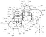
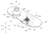
- Fig. 1 is a perspective view of the top side showing an example of the external configuration of a controller 1 according to a first embodiment of the present invention
- Fig. 2 is a perspective view of the bottom side showing an example of the external configuration of the controller 1.
- Fig. 3 is a front view showing an example of the external configuration of the controller 1
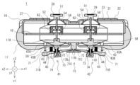
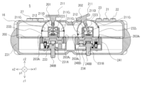
- Fig. 4 is a cross-sectional view of Fig. 3.
- the controller 1 is used to operate the game device, and is roughly composed of a flat operation section 11, a rear operation section 12, a bottom operation section 13, grip sections 14 and 15, an upper case 16, a lower case 17, and a printed circuit board 18.
- an A button 21, a B button 22, an X button 23, and a Y button 24 are arranged on the right side of the flat-surface operation unit 11.
- the xyz coordinate system in FIG. 1 is a coordinate system based on the controller 1, and in the direction perpendicular to the plane of the controller 1, for example, the direction in which the A button 21 is pressed is defined as the z1 direction, and the direction opposite to the z1 direction is defined as the z2 direction.
- the direction from the X button 23 to the B button 22 is defined as the x1 direction
- the opposite direction to the x1 direction is defined as the x2 direction
- the direction from the A button 21 to the Y button 24 is defined as the y1 direction
- the opposite direction to the y1 direction is defined as the y2 direction.
- the xyz coordinate systems in Figures 2 to 4, 7 to 9, 13, 14, 18, and 19 are the same as the xyz coordinate system in Figure 1.
- a start button 25 and a select button 26 are located in the central area of the flat-surface operation unit 11.
- a cross key 27 is located on the left side of the flat-surface operation unit 11.
- Analog sticks 28 and 29 are located below the center of the flat-surface operation unit 11.
- the A button 21, B button 22, X button 23, Y button 24, start button 25, and select button 26 protrude from the upper case 16 in the z2 direction in FIG. 1, and are buttons that can be pressed in the z1 direction.
- the cross key 27 is composed of an up button 27A, a down button 27B, a left button 27C, and a right button 27D.
- the up button 27A, the down button 27B, the left button 27C, and the right button 27D protrude from the upper case 16 in the z2 direction in FIG. 1, and are each buttons that can be pressed in the z1 direction in FIG. 1.
- Analog sticks 28 and 29 are controls that output an analog value according to the direction in which stick 54 is tilted and the angle at which stick 54 is tilted, when the operator uses his or her finger to tilt cap 51 fitted to stick 54 (see Figure 4) that is erected in the z2 direction (neutral position) in any direction, i.e., in the x1-x2 direction, y1-y2 direction, or diagonal direction (360° from the neutral position).
- the analog sticks 28 and 29 have caps 51 that protrude from the upper case 16 in the z2 direction in FIG. 1.
- the analog sticks 28 and 29 may also be capable of being pressed in the z1 direction. The detailed structure, assembly method, and operation of the analog sticks 28 and 29 will be described later with reference to FIGS. 5 to 9.
- the rear operation section 12 of the controller 1 is composed of shoulder buttons 30, 31, 32, and 33. Near the left end of the rear of the controller 1, shoulder button 30 is located on the flat side (z2 direction side), and shoulder button 31 is located on the bottom side (z1 direction side).
- a shoulder button 32 is located on the flat side (z2 direction side) near the right end of the back of the controller 1, and a shoulder button 33 is located on the bottom side (z1 direction side).
- braking units 41 and 42 that constitute the bottom operation unit 13 are disposed in the lower case 17 of the controller 1 at positions facing the analog sticks 28 and 29.
- the braking unit 41 is used to brake the analog stick 28, and the braking unit 42 is used to brake the analog stick 29.
- buttons such as the A button 21, the analog sticks 28 and 29, and the brakes 41 and 42 while holding the grip portion 14 with the left hand and the grip portion 15 with the right hand.
- An example is as follows.
- the operator can operate the select button 26, the cross key 27, and the analog stick 28 with the thumb of the left hand.
- the operator can also operate the shoulder buttons 30 and 31 with the index finger or middle finger of the left hand.
- the operator can also operate the brake unit 41 with the ring finger or middle finger of the left hand.
- the operator can operate the A button 21, B button 22, X button 23, Y button 24, start button 25, and analog stick 29 with the thumb of the right hand.
- the operator can also operate the shoulder buttons 32 and 33 with the index finger or middle finger of the right hand.
- the operator can also operate the brake unit 42 with the ring finger or middle finger of the right hand.
- FIG. 5 is a perspective view of the top side showing an example of the external configuration of the analog sticks 28 and 29, and Fig. 6 is a perspective view of the bottom side showing an example of the external configuration of the analog sticks 28 and 29. Also, Fig. 7 is an exploded perspective view of the analog sticks 28 and 29.
- Analog sticks 28 and 29 have the same structure and are constructed by assembling a cap 51, an upper case 52, an x-axis follower 53, a stick 54, a y-axis follower 55, a lower case 56, a connecting pin 57, a pressure receiving member 58, an x-axis potentiometer 59, a y-axis potentiometer 60, an x-axis centering portion 61, and a y-axis centering portion 62.
- the cap 51 is disc-shaped and is comprised of an operating part 51A that is operated by the operator's thumb, and a dome-shaped cover 51B that is integrally formed to prevent the intrusion of dust and other foreign matter.
- the upper case 52 is rectangular and open at the bottom end.
- the upper case 52 has a circular through-hole 52A formed in the center of the top surface, and notches 52B formed in the center of each side of the bottom end.
- the x-axis follower 53 is constructed by integrally connecting an arc-shaped operating part 53A, a shaft part 53B that connects to one end of the operating part 53A, and a shaft part 53C that connects to the other end of the operating part 53A.
- the operating part 53A is arc-shaped to avoid interference with the y-axis follower 55.
- a rectangular through-hole 53D is formed in the longitudinal direction of the operating part 53A.
- the stick 54 is constructed by integrally connecting cylindrical shafts 54A and 54B with a connecting portion 54C that is rectangular and is provided between shafts 54A and 54B.
- a hole 54D is formed in the center of connecting portion 54C into which connecting pin 57 fits.
- the y-axis follower 55 is constructed by integrally connecting an actuating part 55A, a shaft part 55B connected to one end of the actuating part 55A in the longitudinal direction, and a shaft part 55C connected to the other end of the actuating part 55A in the longitudinal direction.
- a rectangular through hole 55D is formed in the actuating part 55A.
- Two holes 55E into which the connecting pins 57 fit are formed in the center of the actuating part 55A in the longitudinal direction, at positions symmetrical in the lateral direction.
- the lower case 56 is square-shaped, has the same external dimensions on the flat surface as the upper case 52, and is open at the top.
- the lower case 56 has notches 56A formed in the center of each side of the top end, and has a circular through-hole 56B formed in the center of the bottom surface.
- legs 56C are formed in the lower corners of the lower case 56 for fixing it to a printed circuit board 18 (see Figure 4) on which various components are mounted.
- the connecting pin 57 is cylindrical and has the same length in the short direction as the length of the operating part 55A that constitutes the y-axis follower part 55.
- the pressure receiving member 58 is composed of a semi-spherical pressure receiving part 58A and a cylindrical connecting part 58B that are integrally formed.
- a hole 58C is formed in the center of the upper surface of the connecting part 58B into which the lower end of the shaft part 54B of the stick 54 fits.
- the end of the shaft 53C of the x-axis follower 53 is fitted into a through hole 59A formed in the center of the x-axis potentiometer 59, and outputs an electrical signal (analog value) according to the rotation of the x-axis follower 53 in the x1-x2 direction caused by tilting the stick 54.
- the y-axis potentiometer 60 has a through hole 60A formed in the center that fits over the end of the shaft 55C of the y-axis follower 55, and outputs an electrical signal (analog value) that corresponds to the rotation of the y-axis follower 55 in the y1-y2 directions that occurs when the stick 54 is tilted.
- the x-axis centering part 61 has a through hole (not shown) formed in the center, and a pair of leaf springs 61A are provided on the y2 side.
- the y-axis centering part 62 has a through hole 62A formed in the center, and a pair of leaf springs (not shown) are provided on the x2 side.
- the worker inserts the shaft 54A of the stick 54 through the through hole 52A of the upper case 52 while facing the four notches 52B of the upper case 52 to the four notches 56A of the lower case 56, thereby joining the upper case 52 and the lower case 56.
- the upper case 52 and the lower case 56 can be joined by any of the following means: adhesion, fusion, crimping, locking with locking claws and locking holes, etc.
- the worker inserts the end of the shaft portion 55B of the y-axis follower 55, which protrudes from the upper case 52 and the lower case 56 to the x2 side, into a through hole 62A formed in the center of the y-axis centering portion 62, so that it protrudes in the x2 direction, and abuts the end of the shaft portion 55B against a pair of leaf springs (not shown).
- the worker fits the upper end of the shaft 54A of the stick 54, which protrudes upward from the through-hole 52A of the upper case 52, into a hole (not shown) formed at the lower end of the operating part 51A of the cap 51.
- the worker also fits the lower end of the shaft 54B of the stick 54, which protrudes downward from the through-hole 56B of the lower case 56, into a hole 58C formed in the upper surface of the connecting part 58B of the pressure receiving member 58.
- step (f) When mounting the analog sticks 28 and 29 on the controller 1, the worker first attaches the assembly up to step (f) above by fixing the four legs 56C of the lower case 56 to the printed circuit board 18 (see Figure 4). Next, the worker solders the terminals protruding from the bottom ends of the x-axis potentiometer 59, y-axis potentiometer 60, x-axis centering portion 61, and y-axis centering portion 62 to the patterns formed on the printed circuit board 18. Next, the worker performs step (g) above.
- the x-axis follower 53 rotates in the x1 direction
- the shaft 54A of the stick 54 contacts the x2 side of the through hole 53D of the x-axis follower 53
- the x-axis follower 53 rotates in the x2 direction.
- the x-axis potentiometer 59 outputs an electrical signal (analog value) according to the rotation of the x-axis follower 53 in the x1-x2 direction.
- the y-axis follower 55 connected to the stick 54 rotates in the y1-y2 direction according to the amount of movement in the y1-y2 direction when the stick 54 is tilted.
- the y-axis potentiometer 60 outputs an electrical signal (analog value) according to the rotation of the y-axis follower 55 in the y1-y2 direction.
- the x-axis follower 53 and the y-axis follower 55 operate independently, so when the operator operates the operating part 51A of the cap 51 with his or her thumb in any direction within 360° on the xy plane, the x-axis potentiometer 59 and the y-axis potentiometer 60 output an electrical signal corresponding to that operation.
- the x-axis centering section 61 returns the stick 54 to the neutral position due to the restoring force of the leaf spring 61A that was pressed by the end of the shaft portion 53B of the x-axis follower section 53, and the y-axis centering section 62 returns the stick 54 to the neutral position due to the restoring force of the leaf spring (not shown) that was pressed by the end of the shaft portion 55B of the y-axis follower section 55.
- Figure 8 is a perspective view showing an example of the external configuration of the analog sticks 28 and 29 when tilted in the x2 direction.
- Figure 8 it is shown that the x2-direction leaf spring 61A of the x-axis centering portion 61 is curved in the x2 direction.
- Figure 9 is a perspective view showing an example of the external configuration of the analog sticks 28 and 29 when tilted in the x1 direction.
- the x1-direction leaf spring 61A of the x-axis centering portion 61 is curved in the x1 direction.
- FIG. 10 is an exploded perspective view of the braking units 41 and 42 that constitute the controller 1.
- the braking units 41 and 42 have the same structure, and are configured by assembling an operation plate 71, a pressing member 72, a coil spring 73, and an adjustment screw 74.
- the operating plate 71 has a generally I-shaped planar shape and is constructed by integrally forming a base 71A, an operating end 71B connected to one end of the base 71A, and a shaft 71C connected to the other end of the base 71A.
- a through hole 71D is formed in the approximate center of the base 71A, and a female screw 71E is formed on the inner circumferential surface of the through hole 71D.
- the pressing member 72 is configured by integrally forming a disk-shaped pressing portion 72A, a shaft portion 72B having one end connected to the pressing portion 72A, and a pair of fitting portions 72C formed on the outer periphery of the other end of the shaft portion 72B.
- Felt for example, may be attached to the upper surface of the pressing portion 72A.
- a polished metal sheet may be attached to the hemispherical surface of the pressing receiving portion 58A that constitutes the pressing receiving member 58.
- the coil spring 73 has an outer diameter smaller than the outer diameter of the pressing portion 72A of the pressing member 72, and an inner diameter larger than the distance from one fitting portion 72C to the other fitting portion 72C of the pressing member 72.
- the length of the shaft portion 72B of the pressing member 72 excluding the fitting portion 72C is slightly shorter than the free height of the coil spring 73.
- the adjustment screw 74 is configured by integrally forming a cylindrical portion 74A and a hexagonal column-shaped head 74B.
- a male thread 74C is formed on the outer peripheral surface of the cylindrical portion 74A, which screws into a female thread 71E formed on the inner peripheral surface of the through hole 71D of the operation plate 71.
- a bottomed circular hole 74D that houses the coil spring 73 is formed in the cylindrical portion 74A.
- a fitting hole 74E is formed in the bottom surface of the circular hole 74D, into which the other end of the shaft portion 72B of the pressing member 72 and a pair of fitting portions 72C fit.
- a beam 17A is formed integrally with the lower case 17 in the center of the lower case 17 and parallel to the short side direction (y1-y2 direction) of the lower case 17.
- a recess 17B1 into which the shaft 71C of the operation plate 71 is inserted to mount the operation plate 71 rotatably in the z1-z2 directions around the shaft 71C as the center of rotation, and a restriction plate 17B2 for restricting the operation plate 71 from rotating in the z1 direction by more than a predetermined angle are formed at both ends of the recess 17B1 .
- through holes 17C and 17D are formed in the lower case 17 at positions facing the pressure receiving members 58 that constitute the analog sticks 28 and 29.
- the inner diameters of the through holes 17C and 17D are large enough to allow the pressure portion 72A of the pressure member 72 that constitutes the brakes 41 and 42 to be inserted therethrough.
- a through hole (not shown) is formed in the lower case 17 at a position facing the operating end 71B of the operating plate 71 that constitutes the braking units 41 and 42, and the body 43A of the sensor pin 43 is fixed to the periphery of the through hole, and the operating unit 43B, which can be pushed in the z2 direction, protrudes in the z1 direction.
- the sensor pin 43 When the operating end 71B of the operating plate 71 is operated in the z2 direction, causing the operating end 71B to push the actuator 43B into the main body 43A, the sensor pin 43 outputs a detection signal indicating that the operating plate 71 is being operated.
- the controller 1 Based on this detection signal, the controller 1 supplies a signal indicating that the braking unit 41 or 42 is operating to the game device 2 (see FIG. 11) along with an analog value corresponding to the tilt angle of the analog stick 28 or 29.
- the game device 2 When the game device 2 does not receive a signal indicating that the brake unit 41 or 42 is operating, it employs speed control to convert the analog value into the moving speed of the character, etc. On the other hand, when a signal indicating that the brake unit 41 or 42 is operating is received, the game device 2 employs position control to convert the analog value into the distance from the origin coordinates of the character, etc.
- a cylindrical stopper 44 is provided on the bottom surface of the lower case 17 between the sensor pin 43 and the through holes 17C and 17D, protruding in the z1 direction.
- the stopper 44 may be formed integrally with the lower case 17 or may be formed separately from the lower case 17.
- the stopper 44 is provided to prevent the operation plate 71 from being operated in the z2 direction beyond a certain amount, and is provided to set an upper limit for the frictional force generated between the pressure receiving portion 58 and the pressure portion 72A.
- the upper end of the return spring 45 is attached to the bottom surface of the lower case 17 near the outer periphery of the stopper 44 so as to surround the stopper 44.
- the maximum load height (highest compression height) of the return spring 45 is slightly greater than the length of the stopper 44.
- the worker inserts the assembled set of pressing member 72, coil spring 73, and adjustment screw 74 into through hole 71D from the bottom side of operation plate 71, and screws male thread 74C of adjustment screw 74 into female thread 71E.
- the male thread 74C and female thread 71E should be screwed together to the extent that the restoring force of coil spring 73 prevents adjustment screw 74 from coming loose.
- the worker inserts the shaft portion 71C of the operation plate 71 into the recess 17B1 of the beam portion 17A of the braking portion 41 assembled as described above, and attaches it to the lower case 17.
- the worker also attaches the braking portion 42 assembled in the same manner as the braking portion 41 to the lower case 17 so as to be symmetrical to the braking portion 41 with respect to the beam portion 17A as the axis of symmetry.
- the restoring force of the return spring 45 creates a gap between the bottom surface of the pressure receiving member 58 that constitutes the analog sticks 28 and 29 and the top surface of the pressing portion 72A of the pressing member 72 that constitutes the braking units 41 and 42.
- the analog sticks 28 and 29 can be operated in any direction without being braked by the braking units 41 and 42.
- FIG. 11 is a conceptual diagram showing an example of the configuration of a game system 100 including a controller 1.
- the game system 100 includes the controller 1, a game device 2, and a display device 3.
- the game device 2 executes various processes (e.g., game processes) in the game system 100 and displays the results of the processes on the display device 3.
- the game device 2 and the controller 1 are connected by wire or wirelessly, and operation data generated when an operator operates the controller 1 is supplied from the controller 1 to the game device 2.
- the game device 2 is configured so as to be connectable to a game server (not shown) via the network 4.
- the display device 3 is configured, for example, as a liquid crystal display device or an organic EL display device.
- analog stick 28 is set to move the character or a third person in the game space
- analog stick 29 is set to move the viewpoint and aim of the character or the third person.
- FIG. 12 is a diagram showing an example of a game screen displayed on the display device 3 in an FPS shooting game.
- a part of a weapon 101 held by a character, a crosshair 102 for the weapon 101, and a monster 103 that is the target are displayed.
- the operator uses the thumb of the right hand to tilt the cap 51 of the analog stick 29 in the direction in which he or she wants to align the aim 102 with the target monster 103, thereby changing the analog value of the analog stick 29, thereby moving the aim 102 so that it overlaps with the target monster 103.
- the distance between the aim 102 and the monster 103 is small, so the operator only needs to tilt the cap 51 of the analog stick 29 slightly in the x2 direction (see Figure 1).
- the leaf spring 61A of the x-axis centering portion 61 that constitutes the analog stick 29
- the operator tilts the cap 51 of the analog stick 29 in the x2 direction (see FIG. 1) while operating the operation plate 71 that constitutes the braking unit 42 using the ring finger or middle finger of the right hand.
- This causes the pressing portion 72A of the pressing member 72 that constitutes the braking unit 42 to be pressed against the bottom surface of the pressing receiving member 58 that constitutes the analog stick 29, as shown in FIG. 13 and FIG. 14.
- frictional force is generated between the pressure receiving member 58 and the pressing portion 72A, and the operator can use this frictional force as a clue for operation to easily align the aim 102 with the monster 103 compared to when the brake portion 42 is not used.
- the operator can appropriately adjust the frictional force generated between the pressure receiving member 58 and the pressing portion 72A by applying more or less force to the operating end portion 71B with the ring finger or middle finger of the right hand while playing the game.
- the operator can adjust the upper limit of the frictional force as needed by rotating the adjustment screw 74 to change the state of engagement between the male thread 74C of the adjustment screw 74 and the female thread 71E of the operation plate 71 when not playing the game.
- the restoring force of the leaf spring 61A constituting the x-axis centering portion 61 and the leaf spring (not shown) constituting the y-axis centering portion 62 is preferably smaller than the maximum frictional force generated between the pressure receiving portion 58 and the pressing portion 72, i.e., the frictional force generated between the pressure receiving portion 58 and the pressing portion 72 when the upper surface of the operation plate 71 abuts against the lower end of the stopper 44. This is because the tilt angle of the analog stick 28 or 29 is maintained constant even if the operator removes his/her finger from the cap 51 constituting the analog stick 28 or 29 while operating the operation plate 71.
- the controller 1 comprises analog sticks 28 and 29 which output an analog value corresponding to the direction in which the stick 54 is tilted and the angle at which the stick 54 is tilted, a pressure receiving member 58 attached to the stick 54, and braking sections 41 and 42 which brake the analog sticks 28 and 29 by a pressing member 72 which can be pressed against the pressure receiving member 58.
- controller 1 outputs a signal indicating that the braking unit 41 or 42 is operating.
- the controller 1 has a cap 51 attached to one end of a stick 54 that can be tilted by the operator, a pressure receiving member 58 attached to the other end of the stick 54, an operation plate 71 that can be operated in a direction such that the brakes 41 and 42 move toward and away from the pressure receiving member 58, and a pressure member 72 attached to the operation plate 71.
- the restoring forces of the leaf spring 61A of the x-axis centering portion 61 and the leaf spring (not shown) of the y-axis centering portion 62 can be set to be weak so that even an operator with weak muscles can easily operate the analog sticks 28 and 29.
- an operator with weak muscles can easily operate the analog stick 28 or 29 by using only the restoring force of the leaf spring 61A etc. as a clue for operation, for example, by stopping the analog stick 28 or 29 midway or tilting it slowly. Also, because the restoring force of the leaf spring 61A etc. can be set to a weaker value, it becomes easier to return the analog stick 28 or 29 to the neutral position compared to the conventional method.
- the strength of the operation can be adjusted by the degree to which the operator presses the pressing member 72 against the pressing member 58, providing clues for operation according to the operator's preferences. For example, when operating the analog stick 28 or 29 to move a character or the like to a desired position, the character or the like can be accurately moved to the desired position by increasing the force with which the pressing member 72 is pressed against the pressing member 58 as the character approaches the desired position.
- the tilt angle of the analog stick 28 or 29 can be maintained constant.
- the operator operates the analog stick 28 or 29 to tilt it to the desired tilt angle, and then operates the operation plate 71 to press the pressing member 72 against the pressure receiving member 58 to the extent that the analog stick 28 or 29 comes to a stop.
- the operator does not need to continue to apply a force to the cap 51 with his/her fingers that balances the restoring force of the leaf spring 61A of the x-axis centering portion 61 and the leaf spring (not shown) of the y-axis centering portion 62, and can loosen the pressure applied to the cap 51 with his/her fingers or release his/her fingers.
- the analog stick 28 or 29 does not wobble and the operator's fingers do not shake, allowing the operator to maintain a constant tilt angle of the analog stick 28 or 29.
- the operator simply releases the finger pressing the pressing member 72.
- the tilt of the analog stick 28 or 29 near the neutral position can be reflected in the game.
- the operator need only operate the operation plate 71 to press the pressing member 72 against the pressure receiving member 58 to the extent that the analog stick 28 or 29 gradually returns to the neutral position and comes to rest.
- the x-axis centering unit 61 and the y-axis centering unit 62 do not function.
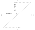
- FIG. 15 is a graph showing an example of the relationship between the tilt angle of the analog sticks 28 and 29 in the x1-x2 direction and the analog value output from the analog sticks 28 and 29.
- the controller 1 simply supplies the game device 2 with an analog value corresponding to the tilt angle of the analog stick 28 or 29 along with a signal indicating that the braking unit 41 or 42 is operating.
- the game device 2 recognizes that the braking unit 41 or 42 is operating, and so can employ the position control to, for example, slightly move a character or a shooting aim in the game space, as intended by the operator, based on the analog value supplied from the controller 1.
- the controller 1 supplies the analog value to the game device 2 together with a signal indicating that the braking unit 41 or 42 is operating.
- the game device 2 recognizes that the braking unit 41 or 42 is operating, and can use the position control to, for example, smoothly move a character or the like in the game space, as intended by the operator, based on the analog value supplied from the controller 1.
- the return operation of the analog stick 28 or 29 can be reflected in the game.
- the controller 1 supplies to the game device 2 an analog value corresponding to the tilt angle of the analog stick 28 or 29 along with a signal indicating that the braking unit 41 or 42 is operating.
- the game device 2 recognizes that the braking unit 41 or 42 is operating, and can determine that the analog value supplied from the controller 1 is due to the return operation and not due to the operation of the x-axis centering unit 61 or y-axis centering unit 62.
- the game device 2 can employ the position control to reflect the analog value resulting from the return operation in the game. For example, if the operator returns the analog stick 28 or 29 to the neutral position with the intention of moving the character, etc. in the opposite direction to the previous movement direction, the character, etc. can be moved in the opposite direction as intended by the operator. In this case, since the x-axis centering unit 61 and the y-axis centering unit 62 are not functioning, the character, etc. will not return to the center position of the game screen, and will remain in the position to which it was moved as long as the operator is operating the operation plate 71.
- the recoil caused by continuing to fire a weapon often causes the aim of the shot to move vertically and horizontally, so the player must adjust the aim of the shot each time by operating the analog stick 28 or 29.
- the operator can easily adjust the aim of the shot by slightly tilting the analog stick 28 or 29 while operating the operation plate 71 that constitutes the brake unit 41 or 42.
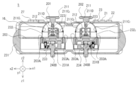
- FIG. 16 is a front view showing an example of the external configuration of the analog sticks 28 and 29 and the braking units 46 and 47 constituting a controller according to a second embodiment of the present invention.
- a braking unit 46 for braking the analog stick 28 and a braking unit 47 for braking the analog stick 29 are newly provided inside the lower case 17, instead of the braking units 41 and 42 of the first embodiment.
- the structure and operation of the other parts of the controller are similar to those of the first embodiment, and therefore a description thereof will be omitted.
- the brake unit 46 has a disk-shaped pressing member 81 and an electromagnetic actuator 82 that, when turned on, causes an operating shaft 82A to protrude and press the pressing member 81 against the pressing receiver 58 with a predetermined pressing force.
- the pressing member 81 is attached to the end of the operating shaft 82A of the electromagnetic actuator 82.
- the brake unit 46 also has a pressing member 81 and an electromagnetic actuator 83 that, when turned on, causes an operating shaft 83A to protrude and press the pressing member 81 against the pressing receiver 58 with a pressing force greater than that of the electromagnetic actuator 82.
- the pressing member 81 is attached to the end of the operating shaft 83A of the electromagnetic actuator 83.
- the braking unit 47 has the same structure as the braking unit 46.
- the number of pressing members 81 is not limited to two, and one or three or more may be provided.
- the electromagnetic actuators 82 and 83 one or more actuators with different pressing forces may be provided.
- the surface area of the pressing member attached to the electromagnetic actuator 83 may be the same as or larger than the surface area of the pressing member 81.
- Table 1 shows an example of the relationship between the on/off state of the electromagnetic actuators 82 and 83 and the frictional force generated between the pressure receiving portion 58 and the pressing member 81.
- the frictional force generated between the pressure receiving portion 58 and the pressing member 81 can be changed in four stages depending on the on/off state of the electromagnetic actuators 82 and 83.
- the on state is represented by a circle and the off state is represented by an x. The same applies to Table 2.
- buttons for turning the electromagnetic actuators 82 and 83 on and off may be provided near the electromagnetic actuators 82 and 83 at a location that can be operated with the middle or ring finger of the left or right hand.
- the function of turning the electromagnetic actuators 82 and 83 on and off may also be set in various buttons (e.g., button A 21 and button B 22) that make up the planar operation unit 11.
- the operator need only operate the analog stick 28 or 29 to tilt it to the desired tilt angle, and then press, for example, a button to turn on the electromagnetic actuator 83 in order to stop the analog stick 28 or 29.
- FIG. 17 is a front view showing an example of the external configuration of the analog sticks 28 and 29 and the brake units 46 and 47 when the electromagnetic actuator 82 is off and the electromagnetic actuator 83 is on.
- the restoring force of the leaf spring 61A constituting the x-axis centering portion 61 and the leaf spring (not shown) constituting the y-axis centering portion 62 is preferably smaller than the maximum frictional force generated between the pressure receiving portion 58 and the pressure member 81, i.e., the state in which the electromagnetic actuators 82 and 83 are both on (see the bottom row of Table 1). This is because the tilt angle of the analog stick 28 or 29 is maintained constant even if the operator removes his or her finger from the cap 51 constituting the analog stick 28 or 29 while the electromagnetic actuator 82 or 83 is on.
- the controller comprises analog sticks 28 and 29 that output an analog value corresponding to the direction in which stick 54 is tilted and the angle at which stick 54 is tilted, a pressure receiving member 58 attached to stick 54, and braking units 46 and 47 that brake analog sticks 28 and 29.
- the cap 51 which is tilted by the operator, is attached to one end of the stick 54, and the pressure receiving member 58 is attached to the other end of the stick 54.
- the brake units 46 and 47 have two pressure members 81 and electromagnetic actuators 82 and 83 that press each pressure member 81 against the pressure receiving member 58.
- the operator can obtain the effect obtained by the first embodiment by simply operating a specified button, without relying on his/her own muscle strength.
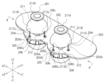
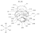
- FIG. 18 is a perspective view showing an example of the external configuration of an analog stick 84 and a braking unit 48 constituting a controller according to a third embodiment of the present invention.
- Fig. 19 is a plan view showing an example of the external configuration of the analog stick 84 and the braking unit 48 in a state in which the cap 51 is removed from the analog stick 84 in Fig. 18.
- an analog stick 84 is newly provided in place of the analog sticks 28 and 29 of the first embodiment.
- a braking unit 48 that brakes the analog stick 84 is newly provided on the printed circuit board 18 in place of the braking units 41 and 42 of the first embodiment.
- the structure and operation of the other parts of the controller are similar to those of the first embodiment, and therefore a description thereof will be omitted.
- the analog stick 84 differs from the analog sticks 28 and 29 in the following ways.
- the stick 54 is configured such that the shaft portion 54B (see FIG. 7) has been removed, and the shaft portion 54A and the connecting portion 54C are integrally connected. Also, the pressure receiving portion 58 shown in FIG. 7 has been removed.
- the shaft portion 53C constituting the x-axis driven portion 53 is inserted into the through hole 59A of the x-axis potentiometer 59, and its length is extended so as to protrude in the y1 direction.
- One end of the rotating shaft 91-1 is connected to the shaft portion 53C.
- the rotating shaft 91-1 is cylindrical except for the one end.
- the cylindrical portion of the rotating shaft 91-1 is rotatably supported by two bearings (not shown) formed in the y1-y2 direction of a square-shaped housing 93.
- a cylindrical pressing receiving portion 92-1 is fitted into the cylindrical portion of the rotating shaft 91-1 that is accommodated in the housing 93.
- the shaft portion 55C constituting the y-axis driven portion 55 is inserted into the through hole 60A (see FIG. 7) of the y-axis potentiometer 60, and its length is extended so as to protrude in the x1 direction.
- One end of the rotating shaft 912 is connected to the shaft portion 55C.
- the rotating shaft 912 is cylindrical except for the one end.
- the cylindrical portion of the rotating shaft 912 is rotatably supported by two bearings 96B (x2 side is not shown) formed in the x1-x2 direction of a square-shaped housing 96.
- a cylindrical pressing receiving portion 922 is fitted into the cylindrical portion of the rotating shaft 912 that is accommodated in the housing 96.
- the brake unit 48 is composed of an x-axis brake unit 48A that brakes the rotation of the x-axis follower unit 53 in the x1-x2 direction, and a y-axis brake unit 48B that brakes the rotation of the y-axis follower unit 55 in the y1-y2 direction.
- the x-axis braking section 48A is composed of pressing members 941 and 951 , and electromagnetic actuators 821 and 831 having the same functions as the electromagnetic actuators 82 and 83 described in the second embodiment.
- the electromagnetic actuators 821 and 831 are attached to the outside of a wall portion 93A on the x1 side of the housing 93.
- An operating shaft 821A of the electromagnetic actuator 821 is inserted into the housing 93 from a through-hole (not shown) formed in the wall portion 93A of the housing 93, and a pressing member 941 is attached to the end thereof.
- An operating shaft 831A of the electromagnetic actuator 831 is inserted into the housing 93 from a through hole (not shown) formed in a wall portion 93A of the housing 93, and a pressing member 951 is attached to the end of the operating shaft 831A.
- the pressing members 941 and 951 are both disk-shaped, and the surface area of the pressing member 951 is larger than the surface area of the pressing member 941 .
- the y-axis braking section 48B is composed of pressing members 942 and 952 , and electromagnetic actuators 822 and 832 having the same functions as the electromagnetic actuators 82 and 83 described in the second embodiment.
- the electromagnetic actuators 822 and 832 are attached to the outside of a wall portion 96A on the y1 side of a housing 96.
- An operating shaft 822A of the electromagnetic actuator 822 is inserted into the housing 96 from a through-hole (not shown) formed in the wall portion 96A of the housing 96, and a pressing member 942 is attached to the end thereof.
- An operating shaft 832A of the electromagnetic actuator 832 is inserted into the housing 96 from a through hole (not shown) formed in a wall portion 96A of the housing 96, and a pressing member 952 is attached to the end of the operating shaft 832A.
- the pressing members 942 and 952 are both disk-shaped, and the surface area of the pressing member 952 is larger than the surface area of the pressing member 942 .
- the pressing members 94-1 and 95-1 provided in the x-axis braking section 48A and the pressing members 94-2 and 95-2 provided in the y-axis braking section 48B are not limited to two each, and may be one or three or more each.
- the electromagnetic actuators 82-1 , 82-2 , 83-1 , and 83-2 may also be provided with one or more actuators with different pressing forces.
- the pressing members 94-1 , 94-2, 95-1 , and 95-2 attached to the electromagnetic actuators 82-1 , 82-2 , 83-1 , and 83-2 may have the same surface area or different surface areas .
- Buttons for turning on and off the electromagnetic actuators 821 , 822 , 831 , and 832 may be provided on the bottom side of the lower case 17 at a location that can be operated with the middle finger or ring finger of the left or right hand. Also, the function of turning on and off the electromagnetic actuators 821 , 822 , 831 , and 832 may be set to various buttons (e.g., button A 21 and button B 22) constituting the flat-surface operation unit 11.
- the restoring force of the leaf spring 61A constituting the x-axis centering portion 61 and the leaf spring (not shown) constituting the y-axis centering portion 62 is preferably smaller than the maximum frictional force generated between the pressure receiving portions 921 and 922 and the pressure members 941 , 942 , 951 and 952 , i.e., the state in which the electromagnetic actuators 821 , 822 , 831 and 832 are all ON (see the bottom row of Table 2). This is because the tilt angle of the analog stick 84 is maintained constant even if the operator releases his/her finger from the cap 51 constituting the analog stick 84 while any of the electromagnetic actuators 821 , 822 , 831 or 832 is ON.
- the controller comprises an analog stick 84 that outputs an analog value corresponding to the direction in which the stick 54 is tilted and the angle at which the stick 54 is tilted, and a braking unit 48 that brakes the analog stick 84.
- the analog stick 84 has a stick 54 that can be tilted in any direction over 360° around a neutral position in the z2 direction, an x-axis follower 53 that rotates in the x1-x2 direction as the stick 54 is tilted, and a y-axis follower 55 that rotates in the y1-y2 direction as the stick 54 is tilted.
- the pressure receiving member 92-1 is attached to the x-axis follower 53, and the pressure receiving member 92-2 is attached to the y-axis follower 55.
- the braking unit 48 is made up of an x-axis braking unit 48A and a y-axis braking unit 48B.
- the x-axis braking unit 48A is made up of pressing members 94-1 and 95-1 , and electromagnetic actuators 82-1 and 83-1
- the y-axis braking unit 48B is made up of pressing members 94-2 and 95-2 , and electromagnetic actuators 82-2 and 83-2 .
- the pressing member 94-1 is pressed against the pressure receiving member 92-1 by the electromagnetic actuator 82-1
- the pressing member 94-2 is pressed against the pressure receiving member 92-2 by the electromagnetic actuator 82-2
- the pressing member 95-1 is pressed against the pressure receiving member 92-1 by the electromagnetic actuator 83-1
- the pressing member 95-2 is pressed against the pressure receiving member 92-2 by the electromagnetic actuator 83-2 .
- the operator can obtain the effects obtained by the first embodiment by simply operating the button, without relying on his/her own muscle strength.
- the analog stick 84 does not have the shaft portion 54B and the pressure receiving portion 58, so that the thickness of the entire controller in the z1-z2 direction can be made thinner, and versatility is high.
- the operator can brake the x-axis follower 53 and the y-axis follower 55 separately and independently.
- the pressure receiving member 922 attached to the y-axis follower 55 rotates, but the pressure receiving member 921 attached to the x-axis follower 53 does not rotate. Therefore, even if the pressing members 941 and 951 are pressed against the pressure receiving member 921 , the force required to tilt the analog stick 84 in the y1 direction or the y2 direction does not change.
- the program can forcibly turn on the electromagnetic actuators 82-2 and 83-2 to clearly inform the operator of the existence of the said restriction.
- the external configuration of a controller according to a fourth embodiment of the present invention does not differ from the external configuration of the controller 1 shown in Figures 1 to 3 except that analog sticks 201 and 202 (see Figure 20, etc.) are newly provided instead of the analog sticks 28 and 29. That is, in the fourth embodiment, the braking unit 41 shown in Figures 1 to 3 is used to brake the analog stick 201, and the braking unit 42 shown in Figures 1 to 3 is used to brake the analog stick 202.
- FIG. 20 is a top perspective view showing an example of the configuration of the analog sticks 201 and 202 and the printed circuit board 203 to which they are attached that constitute a controller according to a fourth embodiment of the present invention.
- FIG. 21 is a bottom perspective view showing an example of the configuration of the analog sticks 201 and 202 and the printed circuit board 203 shown in FIG. 20, and
- FIG. 22 is a cross-sectional view taken along the line A-A in FIG. 20.
- the xyz coordinate system in FIGS. 20 to 22 and FIGS. 27 to 29 described below is the same as the xyz coordinate system in FIG. 1.
- the printed circuit board 203 is formed with through holes 203A -1 to 203A- 8 into which the respective tilt transmission members 204-1 to 204-8 are inserted.
- the suffixes "1 to 8" of the tilt transmission members 204 1 to 204 8 , the holes 211C 1 to 211C 8 of the cap 211 and the holes 206C 1 to 206C 8 of the pressure receiving member 206 are given for convenience to correspond to the suffixes "1 to 8" of the through holes 203A 1 to 203A 8 of the printed circuit board 203 in order to clarify the attachment state of the tilt transmission member 204 to the cap 211 and the pressure receiving member 206.
- the through holes 203A1 to 203A8 of the printed circuit board 203 are given the suffixes "1 to 4" in the order of the x2 side, y1 side, x1 side and y2 side at the mounting position of the analog stick 201, and the suffixes "5 to 8" in the order of the x2 side, y1 side, x1 side and y2 side at the mounting position of the analog stick 202.
- the tilt transmission members 204-1 to 204-8 are of the same shape, material and dimensions, the cap 211 and the pressure receiving member 206 are both symmetrical in shape, and the suffixes "1 to 8" of each reference numeral have no meaning before mounting on the printed circuit board 203. However, after mounting on the printed circuit board 203, this means that the through holes 203A- 1 to 203A- 8 of the printed circuit board 203 are attached to each other with the same suffixes " 1 to 8".
- the tilt transmission members 204-1 to 204-8 are collectively referred to, the term tilt transmission member 204 is used.
- the tilt transmission members 204 1 to 204 8 are bendable but have low elasticity.
- the shape of the tilt transmission members 204 1 to 204 8 may be , for example, a thread, a twisted combination of multiple types of thread-like members, a plate shape, or a rod shape.
- the material of the tilt transmission members 204 1 to 204 8 may be, for example, natural fibers, synthetic fibers such as polyvinylidene fluoride, natural or synthetic fibers coated with natural or synthetic materials, metal, or a combination of natural fibers, synthetic fibers, and metal.
- the tilt transmission members 204 1 to 204 8 do not need to be of the same shape, material, or dimensions overall, and may have different shapes, materials, or dimensions depending on the areas where they are used (e.g., areas that may come into contact with other members).
- a guide/support member 205 and a pressure receiving member 206 are provided on the bottom side of the printed circuit board 203 at a position facing the analog sticks 201 and 202.
- the guide/support member 205 is attached to the bottom surface of the printed circuit board 203.
- the guide/support member 205 guides the tilt transmission members 204.sub.1 to 204.sub.8 to the pressure receiving member 206, and supports the pressure receiving member 206.
- Figure 23 is a perspective view of the bottom side showing an example of the configuration of the guide/support member 205.
- the guide/support member 205 is composed of a cylindrical central portion 205A, four arm portions 205B, and four cylindrical end portions 205C, which are integrally formed.
- One end of each arm portion 205B is connected to the outer circumferential surface near the upper end of the central portion 205A, at positions symmetrical to each other with respect to the central portion 205A. This gives the guide/support member 205 a cross shape when viewed in a plane.
- a cylindrical end 205C is formed at the other end of each arm 205B.
- a through hole 205D is formed in each cylindrical end 205C, into which the corresponding tilt transmission member 204 is inserted.
- the inner circumferential surface of each through hole 205D is smoothly finished so that the tilt transmission member 204 does not wear down due to friction when it comes into contact with the through hole 205D.
- a support recess 205E is formed on the bottom surface of the central portion 205A.
- the tip 206D of the cylindrical portion 206B constituting the pressure receiving member 206 abuts against the support recess 205E, and the tilt transmission member 204 is stretched between the cap 211 and the pressure receiving member 206, so that the guide/support member 205 supports the pressure receiving member 206 so that it can rotate freely with the support recess 205E as a fulcrum.
- the pressure receiving member 206 is configured by integrally forming a hemispherical shell portion 206A with an open upper end and a cylindrical portion 206B that is vertically erected at the lowest part of the inner surface of the hemispherical shell portion 206A.
- Four holes 206C are formed near the upper end of the hemispherical shell portion 206A at positions symmetrical to each other with respect to the cylindrical portion 206B.
- the other end of the corresponding tilt transmission member 204 is attached to each hole 206C.
- the tip portion 206D of the cylindrical portion 206B is hemispherical. The surface of the tip portion 206D is smoothly finished so that the pressure receiving member 206 rotates smoothly in accordance with the tilting operation of the analog sticks 201 and 202.
- Fig. 25 is an exploded perspective view showing an example of the configuration of the analog sticks 201 and 202.
- the analog sticks 201 and 202 have the same structure and are composed of a cap 211 and an analog stick unit 212.
- a commercially available or known analog stick unit can be used for the analog stick unit 212, and the structure is not limited to the structure shown in Fig. 25.
- a known analog stick unit is disclosed in, for example, Japanese Patent No. 7113133.
- the coordinate system in FIG. 25 is the coordinate system for the analog sticks 201 and 202 alone.
- an axis parallel to a first line passing through corners a and b on the flat surface side is defined as a first axis A1.
- An axis parallel to a second line passing through corners a and c on the flat surface side and perpendicular to the first line is defined as a second axis A2.
- An axis parallel to a third line passing through corner a on the flat surface side and corner d on the bottom surface side and perpendicular to the first and second lines is defined as a third axis A3.
- the direction from angle b to angle a is defined as the A11 direction, and the opposite direction of the A11 direction is defined as the A12 direction.
- the direction from angle c to angle a is defined as the A21 direction, and the opposite direction of the A21 direction is defined as the A22 direction.
- the direction from angle a to angle d is defined as the A31 direction, and the opposite direction of the A31 direction is defined as the A32 direction.
- the analog sticks 201 and 202 may be attached to the flat surface of the printed circuit board 203 so that they are symmetrical with respect to a plane parallel to the y1-y2 direction (direction perpendicular to the paper surface) shown in Figure 22.
- the A11-A12 direction of the A1-A3 coordinate system of the analog stick 201 is parallel to the y1-y2 direction of the xyz coordinate system
- the A11-A12 direction of the A1-A3 coordinate system of the analog stick 202 is parallel to the x1-x2 direction of the xyz coordinate system.
- the cap 211 is configured by integrally forming an operating section 211A, which is disk-shaped and operated by the operator's thumb, and a cover 211B, which is a hemispherical shell with an open bottom end and prevents dust and the like from entering the inside of the controller.
- the diameter of the cover 211B is equal to the diameter of the hemispherical shell section 206A constituting the pressing member 206.
- Four holes 211C are formed near the bottom end of the cover 211B, at positions symmetrical to each other with respect to the center of the cover 211B. Only two holes 211C are shown in FIG. 25.
- One end of each of the tilt transmission members 204 1 to 204 8 shown in FIG. 20 to FIG. 22 is attached to each hole 211C.
- the analog stick unit 212 is constructed by assembling an upper case 221, a first axis follower 222, a stick 223, a second axis follower 224, a lower case 225, a connecting pin 226, a centering part 227, a first axis potentiometer 228, and a second axis potentiometer 229.
- the upper case 221 is rectangular and open at the bottom.
- the upper case 221 has a circular through hole 221A formed in the center of the plane, and has notches 221B formed in the center of each side of the bottom end. Only two notches 221B are shown in Figure 25.
- the first shaft follower 222 is configured by integrally forming an arc-shaped operating part 222A, a shaft part 222B that connects to one end of the operating part 222A, and a shaft part 222C that connects to the other end of the operating part 222A.
- the operating part 222A is arc-shaped to avoid interference with the second shaft follower 224.
- a rectangular through hole 222D is formed in the longitudinal direction of the operating part 222A.
- the stick 223 is composed of a cylindrical portion 223A, a rectangular column portion 223B, and a disk portion 223C, which are integrally formed.
- a hole 223D into which the connecting pin 226 fits is formed near the bottom end of the rectangular column portion 223B.
- the second shaft driven part 224 is constructed by integrally forming an actuating part 224A, a shaft part 224B connected to one end of the actuating part 224A in the longitudinal direction, and a shaft part 224C connected to the other end of the actuating part 224A in the longitudinal direction.
- a rectangular through hole 224D is formed in the actuating part 224A.
- Two holes 224E into which the connecting pins 226 fit are formed at positions symmetrical in the short direction at the center of the longitudinal direction of the actuating part 224A.
- the lower case 225 is square-shaped, with the outer dimensions of its planar side being the same as those of the upper case 221, and open at the top.
- the lower case 225 has notches 225A formed in the center of each side of the upper end, and a circular bottomed hole 225B formed in the center of the bottom surface.
- legs 225C are formed in the lower corners of the lower case 225 for fixing it to a printed circuit board 203 (see Figure 20) on which various components are mounted.
- the connecting pin 226 is cylindrical and has a length equal to the short-side length of the actuating portion 224A that constitutes the second shaft follower portion 224.
- Figure 26 is a bottom perspective view showing an example of the configuration of centering portion 227.
- Centering portion 227 is configured by integrally forming disk portion 227A and four leaf spring portions 227B.
- the outer diameter of disk portion 227A is approximately equal to the outer diameter of disk portion 223C constituting stick 223, and is slightly smaller than the inner diameter of bottomed hole 225B of lower case 225.
- Each leaf spring portion 227B is cut into a plate shape so that base portion 227C remains at the four corners of the bottom surface of disk portion 227A, and tip portion 227D faces base portion 227C of adjacent leaf spring portion 227B, and tip portion 227D is pulled out diagonally downward.
- the first axis potentiometer 228 shown in FIG. 25 has an end of the shaft 222C of the first axis follower 222 fitted into a through hole 228A formed in the center, and outputs an electrical signal (analog value) corresponding to the rotation of the first axis follower 222 in the A11-A12 direction caused by tilting the stick 223.
- the second axis potentiometer 229 has a through hole 229A formed in the center, into which the end of the shaft portion 224B of the second axis follower 224 is fitted, and outputs an electrical signal (analog value) corresponding to the rotation of the second axis follower 224 in the A21-A22 direction caused by tilting the stick 223.
- the worker inserts the cylindrical portion 223A of the stick 223 into the through hole 221A of the upper case 221 while facing the four notches 221B of the upper case 221 to the four notches 225A of the lower case 225, thereby joining the upper case 221 and the lower case 225.
- the upper case 221 and the lower case 225 can be joined by any of the following means: adhesion, fusion, crimping, locking with locking claws and locking holes, etc.
- first axis follower 222 When the upper case 221, first axis follower 222, stick 223, second axis follower 224, lower case 225, connecting pin 226, and centering part 227 are assembled, the end of shaft part 222C of first axis follower 222 protrudes from the upper case 221 and lower case 225 toward the A21 side. Also, in this state, the end of shaft part 224B of second axis follower 224 protrudes from the upper case 221 and lower case 225 toward the A12 side.
- the worker attaches the two analog stick units 212 to the printed circuit board 203 so that they are symmetrical with respect to a plane parallel to the y1-y2 direction (a direction perpendicular to the paper surface), as shown in FIG. 22.
- the worker attaches another guide/support member 205 to the bottom surface of the printed circuit board 203, at a position facing the analog stick unit 212 on the x1 side, so that the axes of the through holes 203A5 to 203A8 are aligned with the axes of the four through holes 205D formed in the guide/support member 205.
- the guide/support members 205 may be attached to the printed circuit board 203 by any of fitting, adhesion, screw fastening, locking with locking tabs and locking holes, etc.
- the upper ends of the cylindrical ends 205C of the guide/support members 205 are fitted into the through holes 203A1 , 203A3 , 203A5 , and 203A7 of the printed circuit board 203.
- the analog sticks 201 and 202, tilt transmission member 204, guide/support member 205, and pressure receiving member 206 are mounted on the printed circuit board 203, as shown in Figures 20 to 22.
- FIG. 27 is a perspective view of the top side showing an example of the configuration of the analog stick 201 when not tilted, the analog stick 202 when tilted in the x2 direction, the printed circuit board 203, etc.
- Fig. 28 is a perspective view of the bottom side showing an example of the configuration of the analog sticks 201 and 202 and the printed circuit board 203, etc. shown in Fig. 27, and
- Fig. 29 is a cross-sectional view taken along the line A-A in Fig. 27.
- the analog sticks 201 and 202 mounted as described above tilt the stick 223 fitted into the hole 211D formed at the bottom end of the operating portion 211A of the cap 211.
- the leaf spring portion 227B of the centering portion 227 is pressed downward by the disk portion 223C of the stick 223.
- the first axis follower 222 rotates in the x1 direction
- the first axis follower 222 rotates in the x2 direction
- the first axis potentiometer 228 outputs an electrical signal (analog value) according to the rotation of the first axis follower 222 in the x1-x2 direction.
- the second axis follower 224 connected to the stick 223 rotates in the y1-y2 direction according to the amount of movement in the y1-y2 direction when the stick 223 is tilted.
- the second axis potentiometer 229 outputs an electrical signal (analog value) according to the rotation of the second axis follower 224 in the y1-y2 direction.
- the first axis follower 222 and the second axis follower 224 operate independently, so when the operator operates the operating part 211A of the cap 211 with his or her thumb in any direction within 360° on the xy plane, the first axis potentiometer 228 and the second axis potentiometer 229 output an electrical signal in response to that operation.
- the centering portion 227 returns the stick 223 to the neutral position due to the restoring force of the leaf spring portion 227B that was being pressed by the disc portion 223C of the stick 223.
- a cap 51 and a pressure receiving member 58 are attached to the upper and lower ends of the stick 54, and the pressing portion 72 of the braking portion 41 or 42 is pressed against the pressure receiving member 58 as the member to be braked, i.e., the pressing member 72 is pressed against the pressure receiving member 58 as the member to be braked to suppress the movement of the pressure receiving member 58, thereby braking the analog stick 28 or 29.
- a cap 211 is attached to the upper end of the stick 223, and the cap 211 and the pressure receiving member 206 are connected by a tilt transmission member 204, and the pressing portion 72 of the braking portion 41 or 42 is pressed against the pressure receiving member 206; in other words, the pressing member 72 is pressed against the pressure receiving member 206 as the braked member to suppress the movement of the pressure receiving member 206, thereby braking the analog stick 201 or 202.
- the controller comprises analog sticks 201 and 202 which output an analog value corresponding to the direction in which stick 223 is tilted and the angle at which stick 223 is tilted, a cap 211 attached to one end of stick 223, a pressure receiving member 206 attached to cap 211 as a braked member, and braking units 41 and 42 which brake analog sticks 201 and 202 by pressing a pressure member 72 against pressure receiving member 206 to suppress movement of pressure receiving member 206.
- the fourth embodiment provides the same effect as the first embodiment.
- a commercially available or well-known analog stick unit such as the analog stick unit 212 can be used, so the controller can be developed, designed, and manufactured at lower cost and in a shorter period of time than the controller 1 according to the first embodiment.
- Figure 30 is a perspective view of the top side showing an example of the external configuration of a controller 5 according to a fifth embodiment of the present invention
- Figure 31 is a perspective view of the bottom side showing an example of the external configuration of the controller 5.
- Figure 32 is a cross-sectional view taken along line B-B of Figure 30.
- parts corresponding to the parts in Figures 1 to 4 are given the same reference numerals, and their description will be omitted.
- the xyz coordinate system in Figures 30 to 32 and Figures 33, 34, and 39 described later is the same as the xyz coordinate system in Figure 1.
- the external configuration of the planar side of the controller 5 shown in FIG. 30 is generally similar to the external configuration of the planar side of the controller 1 shown in FIG. 1, except that analog sticks 201 and 202 (see FIG. 25) have been newly provided in place of the analog sticks 28 and 29, and that a lower case 231 has been newly provided in place of the lower case 17.
- the analog sticks 201 and 202 of the fourth embodiment are used in place of the analog sticks 28 and 29 of the first embodiment.
- the shoulder buttons 30 to 33 shown in FIG. 1 are not shown in FIG. 30.
- the external configuration of the bottom side of the controller 5 shown in FIG. 31 differs from the external configuration of the bottom side of the controller 1 shown in FIG. 2 in that a lower case 231 is newly provided instead of the lower case 17, and in that braking parts 41 and 42 are not provided.
- the lower case 231 does not have a portion corresponding to the beam part 17A shown in FIG. 2.
- through holes 231A and 231B are formed in the lower case 231 at positions facing the analog sticks 201 and 202.
- FIG. 33 is a perspective view of the top side showing an example of the configuration of the analog sticks 201 and 202, the braking units 233 and 234, and the printed circuit board 203 to which they are attached, which constitute the controller 5.
- FIG. 34 is a perspective view of the bottom side showing an example of the configuration of the analog sticks 201 and 202, the braking units 233 and 234, and the printed circuit board 203, etc. shown in FIG. 33.
- the analog sticks 201 and 202 and the printed circuit board 203 according to the fourth embodiment are used as they are, but instead of the tilt transmission members 204-1 to 204-8 , the guide/support member 205, the pressure receiving member 206, and the braking sections 41 and 42 according to the fourth embodiment, tilt transmission members 232-1 to 232-4 and braking sections 233 and 234 are newly provided.
- the tilt transmission members 232 1 to 232 4 are collectively referred to as tilt transmission member 232.
- the shape and material of the tilt transmission member 232 are similar to the shape and material of the tilt transmission member 204.
- the meaning of the suffixes " 1 to 8" in each of the holes 211C1 to 211C8 of the cap 211 and the meaning of the suffixes "1 to 4" in the tilt transmission members 2321 to 2324 are the same as the meaning of the suffixes " 1 to 8" in each of the tilt transmission members 2041 to 2048 , the holes 211C1 to 211C8 of the cap 211, and the holes 206C1 to 206C8 of the pressure receiving member 206, as explained in the fourth embodiment.
- Fig. 32 shows only the tilt transmission members 2321 and 2323 and the through holes 203A1 , 203A3 , 203A5 , and 203A7 .
- Fig. 33 shows only the through holes 203A3 , 203A4 , 203A7 , and 203A8 .
- Braking units 233 and 234 are attached to the bottom surface of the printed circuit board 203 at positions facing the analog sticks 201 and 202.
- the braking units 233 and 234 press the tilt transmission member 232 in the z2 direction to brake the analog stick 201 or 202.
- the tilt transmission members 204.sub.1 to 204.sub.4 have one end attached to holes 211C.sub.1 to 211C.sub.4 formed in the cap 211, and pass through opposing through holes 203A.sub.1 to 203A.sub.4 in the printed circuit board 203, and have the other end attached to holes 206C.sub.1 to 206C.sub.4 formed in positions facing the holes 211C.sub.1 to 211C.sub.4 in the hemispherical shell portion 206A.
- the tilt transmission members 204.sub.5 to 204.sub.8 are each attached at one end to a hole 211C.sub.5 to 211C.sub.8 formed in the cap 211, and pass through opposing through holes 203A.sub.5 to 203A.sub.8 in the printed circuit board 203, and each attached at the other end to a hole 206C.sub.5 to 203A.sub.8 formed in a position facing the hole 211C.sub.5 to 211C.sub.8 in the hemispherical shell portion 206A .
- one end of the tilt transmission member 232-1 is attached to a hole 211C- 1 (see FIG. 32) formed on the x2 side of the cap 211, passes through an opposing through-hole 203A- 1 in the printed circuit board 203, enters the inside of the braking portion 233 from the x2 side, exits from the x2 side of the braking portion 233, passes through through-hole 203A -3 , and has the other end attached to a hole 211C- 3 (see FIGS. 32 and 33) formed on the x1 side of the cap 211.
- one end of the tilt transmission member 232-2 is attached to a hole 211C- 2 (not shown) formed on the y1 side of the cap 211, passes through an opposing through-hole 203A- 2 (not shown) in the printed circuit board 203, enters the inside of the braking portion 233 from the y1 side, exits from the y2 side of the braking portion 233, passes through through-hole 203A- 4 , and has the other end attached to a hole 211C- 4 (see FIG. 33) formed on the y2 side of the cap 211.
- one end of the tilt transmission member 232-3 is attached to a hole 211C- 5 (see Figure 32) formed on the x2 side of the cap 211, passes through the opposing through-hole 203A- 5 of the printed circuit board 203 and enters the inside of the braking part 234 from the x2 side, exits from the x2 side of the braking part 234 and passes through through-hole 203A -7 , and the other end is attached to a hole 211C- 7 (see Figures 32 and 33) formed on the x1 side of the cap 211.
- one end of the tilt transmission member 232-4 is attached to a hole 211C- 6 (not shown) formed on the y1 side of the cap 211, passes through an opposing through-hole 203A- 6 (not shown) in the printed circuit board 203, enters the inside of the braking portion 234 from the y1 side, exits from the y2 side of the braking portion 234, passes through through-hole 203A -8 , and has the other end attached to a hole 211C- 8 (see FIG. 33) formed on the y2 side of the cap 211.
- the analog sticks 201 and 202 are indirectly braked by pressing the pressing member 72 against the pressing receiving member 206 attached to the analog sticks 201 and 202 via the tilt transmission members 204-1 to 204-8 to suppress the movement of the pressing receiving member 206 as the braked member.
- the braking units 233 and 234 are used to adjust the tension of the tilt transmission member 232 attached to the analog sticks 201 and 202, that is, the movement of the tilt transmission member 232 as the braked member is suppressed, thereby indirectly braking the analog sticks 201 and 202.
- Figure 35 is an exploded perspective view showing an example of the configuration of the brake units 233 and 234.
- the brake units 233 and 234 have the same structure, and are configured by assembling a housing 241, four bolts 242, four nuts 243, four adjustment springs 244, two tension adjustment members 245, four nuts 246, two return springs 247, a brake member 248, a cover 249, and five screws 250.
- the coordinate system in Fig. 35 is a coordinate system for braking portions 233 and 234 alone.
- an axis parallel to a first straight line passing through guide portions 241B1 and 241B3 described below is defined as a first axis A1.
- An axis parallel to a second straight line passing through guide portions 241B2 and 241B4 described below and perpendicular to the first straight line is defined as a second axis A2.
- An axis parallel to a third straight line perpendicular to the first and second straight lines is defined as a third axis A3.
- the direction from guide portion 241B3 to guide portion 241B1 is defined as the A11 direction, and the opposite direction to the A11 direction is defined as the A12 direction.
- the direction from guide portion 241B4 to guide portion 241B2 is defined as the A21 direction, and the opposite direction to the A21 direction is defined as the A22 direction.
- the direction from the top surface side to the bottom surface side is defined as the A31 direction, and the opposite direction to the A31 direction is defined as the A32 direction.
- the reason why the A1-A3 coordinate system of the braking parts 233 and 234 alone is different from the xyz coordinate system based on the controller is the same as the A1-A3 coordinate system of the analog sticks 201 and 202 alone in Figure 25.
- the A1-A3 coordinate system in Figures 36 to 38, which will be described later, is the same as the A1-A3 coordinate system in Figure 35.
- FIG. 36 is a perspective view of the planar side showing an example of the configuration of the housing 241.
- Through holes 241AA 1 to 241AA 4 into which four bolts 242 are respectively inserted are formed in a housing main body 241A of the housing 241.
- Bottomed holes against which the bottom surfaces of the heads of the respective bolts 242 abut are formed around the upper ends of the through holes 241AA 1 to 241AA 4 .
- guide portions 241B 1 to 241B 4 are formed integrally with the housing main body 241A, symmetrically with respect to the center of the housing main body 241A and at positions which correspond to the through holes 203A 1 to 203A 4 or the through holes 203A 5 to 203A 8 of the printed circuit board 203 when the housing 241 is mounted on the printed circuit board 203.
- Through holes 241BA 1 to 241BA 4 are formed in the A31-A32 direction of each of the guide portions 241B 1 to 241B 4.
- the guide portion 241B 1 and the guide portion 241B 3 are combined, and the guide portion 241B 2 and the guide portion 241B 4 are combined to guide the tilt transmission member 232 into and out of the housing main body 241A.
- the tilt transmission member 232 inserted from one of the through holes 241BA1 or 241BA3 or 241BA2 or 241BA4 is guided into the housing main body 241A and is guided from the other through hole 241BA3 or 241BA1 or 241BA4 or 241BA2 to the outside of the housing main body 241A.
- mating projections 241C1 to 241C4 are integrally formed with the corresponding guide portions 241B1 to 241B4 .
- the mating projections 241C1 to 241C4 are configured by integrally forming mating portions 241CA1 to 241CA4 and abutment portions 241CB1 to 241CB4 connected to the lower ends of the corresponding mating portions 241CA1 to 241CA4 .
- the fitting portions 241CA 1 to 241CA 4 are cylindrical and have corresponding through holes 241BA 1 to 241BA 4 formed in their centers .
- the contact portions 241CB1 to 241CB4 are cylindrical with an outer diameter larger than that of the corresponding fitting portions 241CA1 to 241CA4 , and have corresponding through holes 241BA1 to 241BA4 formed in their centers.
- the corresponding fitting portions 241CA1 to 241CA4 are fitted into the through holes 203A1 to 203A4 or the through holes 203A5 to 203A8 of the printed circuit board 203, the upper surfaces of the contact portions 241CB1 to 241CB4 become the bottom surfaces of the printed circuit board 203, and come into contact with the peripheries of the through holes 203A1 to 203A4 or the through holes 203A5 to 203A8 .
- Contact portions 241D1 and 241D2 are formed integrally with the housing body 241A near the center and ends of the top surface of the housing body 241A.
- the contact portions 241D1 and 241D2 have different outer diameters, but are both cylindrical.
- the contact portions 241CB 1 to 241CB 4 and 241D 1 and 241D 2 are formed on the bottom side of the printed circuit board 203 in order to avoid interference with parts and soldered portions mounted in positions opposite the braking portions 233 and 234 .
- the bottom side of the housing body 241A is formed with an accommodation section 241E that accommodates the adjustment spring 244, tension adjustment member 245, return spring 247, braking member 248, etc.
- Five circular holes 241F are formed on the periphery of the bottom side of the housing body 241A for attaching the cover 249 to the bottom surface of the housing 241.
- Each nut 243 is screwed onto each bolt 242 and is used to secure the corresponding bolt 242 to the housing 241.
- each tension adjustment member 245 has through holes 245A near both ends into which the bolts 242 are inserted.
- a protrusion 245B is formed in the center of the upper surface of each tension adjustment member 245 to adjust the tension of the tilt transmission member 232 when the braking parts 233 and 234 are not in use by being pressed against the tilt transmission member 232.
- Each adjustment spring 244 is loosely fitted to each bolt 242, and is used to maintain the tension adjustment state of the tilt transmission member 232 by each tension adjustment member 245 through its restoring force.
- Each nut 246 is screwed onto each bolt 242, and is used to adjust the tension of the tilt transmission member 232 by each tension adjustment member 245 depending on the degree of screwing.
- the braking member 248 is configured by integrally forming a pressing portion 248A and a cylindrical braking button 248B.
- the pressing portion 248A is configured by integrally forming pressing protrusions 248C1 to 248C3 , pressing protrusions 248D1 and 248D2 , and plate portions 248E1 and 248E2 .
- the pressing protrusions 248C1 to 248C3 are arranged side by side at the same height on a first straight line parallel to the A11-A12 direction, and a groove 248C4 is formed between the pressing protrusions 248C2 and 248C3 .
- the pressing protrusions 248D1 and 248D2 are arranged side by side at the same height on a second straight line that is perpendicular to the first straight line and parallel to the A21-A22 direction.
- the pressing protrusions 248C1 to 248C3 are guided to the accommodation portion 241E of the housing main body 241A and pressed against one of the tilt transmission members 232 arranged on the first straight line.
- the pressing protrusions 248D1 and 248D2 are guided to the accommodation portion 241E of the housing main body 241A and pressed against the other of the tilt transmission members 232 arranged on the second straight line.
- the groove 248C4 is formed to prevent the two orthogonal tilt transmission members 232 from contacting each other. Meanwhile, inside the accommodating portion 241E of the housing 241A body, for the same reason as the groove 248C4 , protrusions 241G1 and 241G3 having a first height and protrusions 241G2 and 241G4 having a second height higher than the first height are formed integrally with the housing body 241A (see FIG. 38).
- Each return spring 247 shown in Figure 35 is accommodated between the accommodation portion 241E of the housing 241 and the plate portions 248E1 and 248E2 (see Figure 37) of the pressing portion 248A that constitutes the braking member 248, and is used to return the operated braking member 248 to its original position by its restoring force.
- the cover 249 has the same outer diameter shape and dimensions as the housing 241 in order to cover the entire bottom surface of the housing 241.
- the cover 249 is configured by integrally forming a cover main body 249A and extension portions 249B 1 to 249B 4.
- a through hole 249C into which the brake button 248B of the brake member 248 is loosely fitted is formed in approximately the center of the cover main body 249A.
- Five through holes 249D are formed in the cover main body 249A at positions corresponding to the five circular holes 241F formed on the periphery of the bottom surface side of the housing main body 241A.
- Each screw 250 is inserted into each through hole 249D of the cover body 249A and screwed into the corresponding circular hole 241F of the housing body 241A, thereby attaching the cover 249 to the housing 241.
- the worker attaches one of the housings 241 by fitting the fitting portions 241CA 3 , 241CA 2 , 241CA 1 and 241CA 4 formed in the housing 241 into the through holes 203A 1 to 203A 4 of the printed circuit board 203, respectively.
- the worker also attaches the other housing 241 by fitting the fitting portions 241CA 4 , 241CA 3 , 241CA 3 and 241CA 1 formed on the housing 241 into the through holes 203A 5 to 203A 8 of the printed circuit board 203, respectively.
- each housing 241 attaches to the bottom surface of the printed circuit board 203 so that they are symmetrical about a plane parallel to the y1-y2 direction, as shown in Figures 32 and 34.
- each housing 241 can be attached to the printed circuit board 203 by any of the following means: adhesion, screw fastening, locking with locking tabs and locking holes, etc.
- the contact portions 241CB 1 to 241CB 4 , 241D 1 and 241D 2 formed on each housing 241 come into contact with the bottom surface of the printed circuit board 203 .
- the worker also attaches one end of each of the tilt transmission members 232 3 and 232 4 to holes 211 C 5 and 211 C 6 formed in the vicinity of the lower end of the cover 211 B of the cap 211 that constitutes the analog stick 202 .
- the worker attaches the other end of the tilt transmission member 232 1 to the hole 211 C 3 formed in the vicinity of the lower end of the cover 211 B of the cap 211 that constitutes the analog stick 201 .
- the worker attaches the other end of the tilt transmission member 232 2 to the hole 211 C 4 formed near the lower end of the cover 211 B of the cap 211 that constitutes the analog stick 201 so that the tension is the same as that of the tilt transmission member 232 1 .
- FIG. 38 is a perspective view of the bottom side showing an example of the configuration of the housing 241 into which the tilt transmission members 232 1 and 232 2 are inserted.
- the worker performs steps similar to those of (g) to (i) above on the housing 241 attached to the analog stick 202 and the through holes 203A5 to 203A8 of the printed circuit board 203, thereby attaching the tilt transmission members 2323 and 2324 to the housing 241.
- the operator operates the analog sticks 201 and 202 to check the tension of the tilt transmission members 232-1 to 232-4 .
- the operator changes the state of engagement of the nut 246 with the bolt 242 to change the state of contact of the convex portion 245B of the tension adjustment member 245 with the tilt transmission members 232-1 to 232-4 , thereby adjusting the tension of the tilt transmission members 232-1 to 232-4 .
- the worker aligns the axis of the five through holes 249D of the cover 249 with the axis of the five circular holes 241F of the housing 241, and while pressing the return spring 247 with the cover 249 and braking member 248, inserts each screw 250 into each through hole 249D of the cover 249 and screws it into each circular hole 241F of the housing 241, thereby attaching the cover 249, braking member 248, and return spring 247 to the housing 241.
- the analog sticks 201 and 202, the tilt transmission members 232 1 to 232 4 and the brake parts 233 and 234 are mounted on the printed circuit board 203 as shown in FIGS.
- Figure 39 is a cross-sectional view of the controller 5, and shows a state in which the analog stick 201 is not tilted, a state in which the analog stick 202 is tilted in the x2 direction, a state in which the brake unit 233 is not operated, and a state in which the brake unit 234 is operated.
- the two tilt transmission members 232 are attached at both ends to two pairs of opposing holes 211C formed in the cover 211B of the cap 211 that constitutes the analog stick 201, and are stretched perpendicularly at a predetermined distance within the braking section 233 provided on the bottom side of the printed circuit board 203. The same is true for the analog stick 202 and the braking section 234.
- the operator uses the middle or ring finger of the right hand to press the brake button 248B located on the bottom side of the controller 5 in the z2 direction against the restoring force of the return spring 247.
- the pressing protrusions 248D1 and 248D2 that constitute the braking member 248 are pressed against the tilt transmission member 2323 , and the pressing protrusions 248C1 to 248C3 are pressed against the tilt transmission member 2324 , thereby braking the analog stick 202.
- the tilted state of the analog stick 202 in the x2 direction is maintained.
- the operator simply removes the middle or ring finger of his/her right hand from the braking button 248B. This causes the braking button 248B to be pushed back in the z1 direction by the restoring force of the return spring 247, and the braking portion 234 is released from pressing the tilt transmission members 232-3 and 232-4 .
- the method of operating the analog sticks 201 and 202 is the same as in the first embodiment except as described above, so a description of this method will be omitted.
- the controller 5 comprises analog sticks 201 and 202 that output an analog value corresponding to the direction in which the stick 223 is tilted and the angle at which the stick 223 is tilted, a cap 211 attached to one end of the stick 223, tilt transmission members 232.sub.1 to 232.sub.4 as braked members attached to the cap 211, and braking units 233 and 234 that brake the analog sticks 201 and 202 by pressing a braking member 248 against the tilt transmission members 232.sub.1 to 232.sub.4 to suppress the movement of the tilt transmission members 232.sub.1 to 232.sub.4 .
- the same effects as those obtained by the fourth embodiment can be obtained.
- the guide/support member 205 and the pressure receiving member 206 according to the fourth embodiment are removed, and most of the members that suppress the movement of the tilt transmission members 232.sub.31 to 232.sub.4 can be housed compactly in the brake parts 233 and 234. Therefore, according to the fifth embodiment, the thickness of the entire controller 5 in the z1-z2 direction can be made thinner than that of the controller according to the fourth embodiment, and the controller is highly versatile.
- Figure 40 is a perspective view of the top side showing an example of the external configuration of a controller 6 according to a sixth embodiment of the present invention
- Figure 41 is a perspective view of the bottom side showing an example of the external configuration of the controller 6.
- parts corresponding to the parts in Figures 30 to 32 are given the same reference numerals, and their description will be omitted.
- the xyz coordinate system in Figures 40 and 41, and Figures 42 to 44 and Figures 49 to 51 described later, is the same as the xyz coordinate system in Figure 1.
- the external configuration of the planar side of the controller 6 shown in FIG. 40 is generally similar to the external configuration of the planar side of the controller 5 shown in FIG. 30, except that a lower case 251 has been newly provided in place of the lower case 231. Note that, like FIG. 30, the shoulder buttons 30 to 33 shown in FIG. 1 are not shown in FIG. 40.
- the external configuration of the bottom side of controller 6 shown in FIG. 41 differs from the external configuration of the bottom side of controller 5 shown in FIG. 31 in that a lower case 251 is newly provided instead of lower case 231, a portion of brake button 248B constituting brake units 233 and 234 does not protrude downward, and switches 261 to 264 are newly provided for controlling brake units 254 to 257, which will be described later.
- braking units 254 to 257 that brake the analog sticks 201 and 202 are newly provided and housed inside the controller 6, instead of the braking units 233 and 234.
- Figure 42 is a perspective view of the top side showing an example of the configuration of the analog sticks 201 and 202, braking units 254 and 256, and the printed circuit board 252 on which they are attached, which constitute the controller 6.
- FIG. 43 is a bottom perspective view showing an example of the configuration of the analog sticks 201 and 202, the braking units 255 and 257, the printed circuit board 252, etc.
- FIG. 44 is a plan view showing an example of the configuration of the analog sticks 201 and 202, the braking units 254 and 256, the printed circuit board 252, etc.
- the analog sticks 201 and 202 according to the fifth embodiment are used as is. Also, in the sixth embodiment, a printed circuit board 252, braked members 253 1 to 253 4 , and braking portions 254 to 257 are newly provided in place of the printed circuit board 203, tilt transmission members 232 1 to 232 4 , and braking portions 233 and 234 according to the fifth embodiment.
- the braked members 253 1 to 253 4 are collectively referred to as braked members 253.
- the shape and material of the braked members 253 are similar to the shape and material of the tilt transmitting members 204 and 232.
- the braking units 233 and 234 are used to simultaneously adjust the tension of the two tilt transmission members 232 attached to the analog sticks 201 and 202, i.e., the movement of the two tilt transmission members 232 as braked members is simultaneously suppressed, thereby indirectly braking the analog sticks 201 and 202.
- the braking units 254 to 257 are used to separately adjust the tension of the two braked members 253 that are attached to the analog sticks 201 and 202 and perpendicular to the x1-x2 direction and the y1-y2 direction, i.e., the analog sticks 201 and 202 are indirectly braked by separately suppressing the movement of the two braked members 253.
- the braking portion 254 is attached to the flat surface of the printed circuit board 252, and adjusts the tension of the braked member 253-1 attached to holes 211C- 1 and 211C- 3 of the cap 211 that constitutes the analog stick 201, thereby braking the tilt of the analog stick 201 in the x1-x2 directions.
- the braking portion 255 is attached to the bottom surface of the printed circuit board 252, and adjusts the tension of the braked member 253-2 attached to the holes 211C- 2 and 211C- 4 of the cap 211 that constitutes the analog stick 201, thereby braking the tilt of the analog stick 201 in the y1-y2 directions.
- the braking portion 256 is attached to the flat surface of the printed circuit board 252, and adjusts the tension of the braked member 253.3 attached to the holes 211C.sub.5 and 211C.sub.7 of the cap 211 that constitutes the analog stick 202, thereby braking the tilt of the analog stick 202 in the x1-x2 directions.
- the braking portion 257 is attached to the bottom surface of the printed circuit board 252, and adjusts the tension of the braked member 2534 attached to the holes 211C6 and 211C8 of the cap 211 that constitutes the analog stick 202, thereby braking the tilt of the analog stick 202 in the y1-y2 directions.
- the meaning of the suffixes " 1 to 8" in each of the holes 211C1 to 211C8 of the cap 211 and the meaning of the suffixes " 1 to 4" in the braked members 2531 to 2534 are the same as the meaning of the suffixes " 1 to 8" in each of the tilt transmission members 2041 to 2048 , the holes 211C1 to 211C8 of the cap 211, and the holes 206C1 to 206C8 of the pressure receiving member 206, as explained in the fourth embodiment.
- the suffix "Lx” means that the tilt in the x1-x2 direction of the analog stick 201 provided on the x2 side of the controller 6, i.e., the left side, is braked.
- the suffix "Ly” means that the tilt in the y1-y2 direction of the analog stick 201 is braked.
- the suffix "Rx” means that the tilt of the analog stick 202 on the x1 side of the controller 6, i.e., on the right side, in the x1-x2 direction is damped. Also, the suffix "Ry” means that the tilt of the analog stick 202 in the y1-y2 direction is damped.
- Through holes 252A1 to 252A4 are formed in the printed circuit board 252.
- the through holes 252A1 to 252A4 are formed in the same positions as the through holes 203A2 , 203A4 , 203A6 , and 203A8 of the printed circuit board 203 described in the fourth and fifth embodiments.
- a braked member 2532 is inserted into the through holes 252A1 and 252A2
- a braked member 2534 is inserted into the through holes 252A3 and 252A4 .
- Fig. 42 only the through holes 252A2 and 252A4 are shown, while in Fig. 43, only the braked members 2532 and 2534 are shown, and in Fig. 44, only the braked members 2531 and 2533 are shown.
- one end of the braked member 253-1 is attached to a hole 211C- 1 (not shown) formed on the x2 side of the cap 211.
- the braked member 253-1 After hanging down from the hole 211C- 1 , the braked member 253-1 passes through a guide member 258-1 (see FIG. 44) provided at a position on the printed circuit board 252 opposite the hole 211C- 1 , and then has its path changed in the y1 direction to enter the braking section 254 from the x2 side.
- the handling of the braked member 253-1 within the braking section 254 will be described later with reference to FIG. 45.
- the braked member 253-1 exits from the x1 side of the braking portion 254, passes through a guide member 258-2 provided at a position on the printed circuit board 252 opposite a hole 211C- 3 (see FIG. 42) formed on the x1 side of the cap 211 , has its path changed in the z2 direction, and then the other end is attached to the hole 211C- 3 .
- one end of the tilt transmission member 2322 is attached to a hole 211C2 (not shown) formed on the y1 side of the cap 211.
- the tilt transmission member 2322 hangs down from the hole 211C2 and then passes through a through hole 252A1 (see FIG. 44) provided on the printed circuit board 252 at a position opposite the hole 211C2 , and reaches the bottom side of the printed circuit board 252.
- a guide member 259 is attached to the bottom surface of the printed circuit board 252 at a position on the line connecting the through holes 252A1 and 252A2 .
- through holes 259A and 259B having axes coinciding with the axes of the through holes 252A1 and 252A2 are formed.
- a guide portion 259C that guides the braked member 253.2 that has passed through the through hole 259A to the braking portion 255
- a guide portion 259D that guides the braked member 253.2 that has come out of the braking portion 255 to the through hole 259B side.
- the braked member 2532 that has passed through the through hole 252A1 of the printed circuit board 252 passes through the through hole 259A of the guide member 259, and is then guided by the guide portion 259C to the braking portion 255.
- the handling of the braked member 2532 within the braking portion 255 will be described later with reference to FIG.
- the braked member 253-2 coming out of the braking portion 255 is guided toward the through hole 259B by the guide portion 259D, and then passes through the through hole 259B and comes out onto the flat side through the through hole 252A -2 of the printed circuit board 252, and the other end is attached to the hole 211C- 4 (see Figure 42) formed on the y2 side of the cap 211.
- one end of the braked member 253.3 is attached to a hole 211C.sub.5 (not shown ) formed on the x2 side of the cap 211.
- the braked member 253.3 passes through a guide member 258.sub.3 (see FIG. 44) provided at a position on the printed circuit board 252 opposite the hole 211C.sub.5 , its path is changed in the y1 direction, and it enters the braking section 256 from the x2 side.
- the handling of the braked member 253.3 within the braking section 256 will be described later with reference to FIG. 45.
- the braked member 2533 exits from the x1 side of the braking portion 256, passes through a guide member 2584 provided at a position on the printed circuit board 252 opposite a hole 211C7 (see Figure 42) formed on the x1 side of the cap 211, has its path changed in the z2 direction, and then has the other end attached to the hole 211C7 .
- one end of the tilt transmission member 232-4 is attached to a hole 211C- 6 (not shown) formed on the y1 side of the cap 211.
- the tilt transmission member 232-4 hangs down from the hole 211C- 6 and then passes through a through hole 252A- 3 (see FIG. 44) provided on the printed circuit board 252 at a position opposite the hole 211C- 6 , and reaches the bottom side of the printed circuit board 252.
- a guide member 259 is attached so as to be symmetrical with the guide member 259 on the braking section 255 side with respect to a plane parallel to the y1-y2 direction.
- the braked member 253-4 which has passed through the through hole 252A- 3 of the printed circuit board 252, passes through the through hole 259B of the guide member 259, and is then guided by the guide portion 259D to the braking portion 257.
- the handling of the braked member 253-4 within the braking portion 257 will be described later with reference to FIG.
- the braked member 253-4 coming out of the braking portion 257 is guided by the guide portion 259C toward the through hole 259A side, passes through the through hole 259A, and comes out to the flat side from the through hole 252A- 4 of the printed circuit board 252, and the other end is attached to the hole 211C- 8 (see Figure 42) formed on the y2 side of the cap 211.
- [Structure of Brake Parts 254 to 257] 45 is a plan view showing an example of the configuration of the braking units 254 to 257.
- the braking units 254 to 257 have the same structure, and are configured by assembling a base plate 271, a motor 272, a bearing 273, a worm 274, a pressing member 275, a rotating shaft 276, a stopper 277, and a guide member 278.
- the base plate 271 is generally rectangular and flat.
- a motor 272 is attached to a flat surface near one corner of the base plate 271 via a mounting member 272B (see Figures 42 and 43) so that the rotation shaft 272A is parallel to the longitudinal direction of the base plate 271.
- a mounting member 272B see Figures 42 and 43
- guide portions 271A and 271B that guide the braked member 253 are integrally formed on both ends of the long side opposite the attachment position of the motor 272.
- a worm 274 is fitted to the rotating shaft 272A of the motor 272.
- One end of the rotating shaft 272A is supported by a bearing 273.
- a cord 272C is connected to one end of the motor 272, and power is supplied to the motor 272 from the printed circuit board 252 via a connector 272D.
- a pressing member 275 having a worm wheel portion 275A that screws into the worm 274 at a right angle is provided near the worm 274 and is supported by a rotating shaft 276.
- the axis of the rotating shaft 276 is perpendicular to the axis of the rotating shaft 272A.
- the pressing member 275 is formed integrally with the worm wheel portion 275A and the tongue portion 275B.
- the arcuate side of the tongue portion 275B is formed with a pressing groove portion 275C (see FIG. 42) for adjusting the tension of the braked member 253 by pressing it against the braked member 253.
- the tongue portion 275B has flat side surfaces 275D and 275E formed on the side that connects with the worm wheel portion 275A.
- a cylindrical stopper 277 is attached near the bearing 273.
- the flat side surface 275D of the pressing member 275 abuts against the stopper 277, thereby restricting the rotation of the pressing member 275 in the B direction.
- Worm gears have the advantage that even if you try to rotate the worm 274 from the worm wheel portion 275A side, a self-locking phenomenon occurs and the gear will not operate, and that there is less backlash than with other gear mechanisms.
- the tension of the braked member 253 can be kept constant even when the motor 272 is stopped.
- Two guide members 278 are provided near each of the guide portions 271A and 271B of the base plate 271. Each guide member 278 is provided so that the surface through which the braked member 253 is inserted is perpendicular to the surface through which the braked member 253 is inserted in the guide portions 271A and 271B, and is parallel to the short side direction of the base plate 271.
- the braked member 253 1 that has entered the braking portion 254 is guided by the guide portion 271 B, and is guided by a guide member 278 provided nearby, and is changed in direction so as to be parallel to the longitudinal direction of the base plate 271 .
- the braked member 253-1 comes into contact with the pressing groove portion 275C (see FIG. 42) formed on the arcuate side surface of the tongue-shaped portion 275B constituting the pressing member 275, reaches the opposing guide member 278, is guided by the guide member 278 to the guide portion 271A, is changed in direction so as to be parallel to the short side direction of the base plate 271, and then comes out of the braking portion 254.
- the braked members 253-2 and 253-3 that enter the braking portions 255 and 256 are handled in the same manner as the braked member 253-1 that enters the braking portion 254.
- the braked member 253-4 that enters the braking portion 257 is handled in the opposite manner to the braked member 253-1 that enters the braking portion 254, entering through the guide portion 271A and exiting through the guide portion 271B.
- FIG. 46 is a block diagram showing an example of the configuration of a control unit 265 that controls a motor 272 constituting the braking units 254 to 257 based on signals SNF Lx , SNF Ly , SNF Rx and SNF Ry indicating the on or off state of the switches 261 to 264 .
- the control section 265 is made up of a control circuit 281, drive circuits 282Lx , 282Ly , 282Rx , and 282Ry , and current detection circuits 283Lx , 283Ly , 283Rx , and 283Ry .
- control circuit 281 drive circuits 282Lx , 282Ly , 282Rx , and 282Ry , and current detection circuits 283Lx , 283Ly , 283Rx , and 283Ry .
- the control circuit 281 is composed of, for example, a microcomputer.
- a control circuit that executes various processes in the controller 6 may be configured to execute the functions of the control circuit 281.
- the control circuit 281 supplies the corresponding drive circuit 282 with a signal SSM for starting or stopping the corresponding motor 272, and a signal RPR for indicating the direction of rotation (forward or reverse) of the motor 272.
- Each drive circuit 282 is composed of, for example, an amplifier. Based on the signal SSM and the signal RPR supplied from the control circuit 281, each drive circuit 282 supplies or stops power to the corresponding motor 272 via the corresponding current detection circuit 283 in order to start or stop the corresponding motor 272 according to the specified rotation direction.
- FIG. 47 is a diagram showing an example of the current consumption characteristics of a certain motor 272.
- the motor 272 When the motor 272 is rotated forward, the current consumption of the motor 272 increases sharply in the start-up section ST as shown in Figure 47, and then decreases.
- the pressing member 275 rotates in the direction A shown in Figure 45, and the pressing groove portion 275B of the tongue-shaped portion 275B constituting the pressing member 275 presses the braked member 253.
- the load (rotational resistance) of the motor 272 increases, and the current consumption gradually increases.
- each current detection circuit 283 supplies a signal DOC indicating this to the control circuit 281.
- the control circuit 281 supplies a signal SSM to the corresponding drive circuit 282 based on the signal DOC supplied from each current detection circuit 283 to stop the corresponding motor 272.
- FIG. 48 is a flowchart for explaining the braking process executed by the control circuit 281. Note that the process of each step in the flowchart shown in Fig. 48 is merely an example, and the order of the process of each step may be changed, or another process may be executed in addition to (or instead of) the process of each step, as long as the same result is obtained.
- step S1 When the controller 6 is powered on, the control circuit 281 first proceeds to step S1 shown in FIG. 48, where it determines whether a certain switch (e.g., switch 261) has been turned on and a signal SNF indicating that the switch is on has been supplied. If the determination result in step S1 is "YES", the control circuit 281 proceeds to step S2.
- a certain switch e.g., switch 261
- step S2 the control circuit 281 supplies a signal RPR to the drive circuit 282 corresponding to the signal SNF to indicate the direction of rotation of the corresponding motor 272 (in this case, forward rotation), and then proceeds to step S3.
- step S3 the control circuit 281 supplies a signal SSM to the drive circuit 282 corresponding to the signal SNF to start the corresponding motor 272, and then proceeds to step S4.
- the drive circuit 282 to which the signal SSM and the signal RPR are supplied from the control circuit 281, supplies power to the corresponding motor 272 via the corresponding current detection circuit 283 in order to start the corresponding motor 272 in the forward direction.
- the corresponding current detection circuit 283 monitors the current consumption of the corresponding motor 272.
- step S4 the control circuit 281 determines whether the switch has been turned off and whether a signal SNF indicating that the switch is off has been supplied. If the determination result in step S4 is "NO", the control circuit 281 proceeds to step S5.
- step S5 the control circuit 281 determines whether or not a signal DOC indicating that the current consumption has reached the overcurrent level LOC has been supplied from the current detection circuit 283 corresponding to the switch. If the determination result in step S5 is "YES", the control circuit 281 proceeds to step S6.
- step S6 the control circuit 281 supplies a signal SSM to the drive circuit 282 corresponding to the signal DOC to stop the corresponding motor 272. After that, the control circuit 281 returns to step S4 and repeats the processes from step S4 onwards.
- the control circuit 281 supplies a signal SSM Ry to the drive circuit 282 Ry for stopping the motor 272 Ry , and then returns to step S4.
- the drive circuit 282 Ry stops supplying power to the motor 272 Ry via the current detection circuit 283 Ry , and the motor 272 Ry stops.
- step S5 if the result of the determination in step S5 is "NO", that is, if the signal DOC is not supplied from the current detection circuit 283 corresponding to the switch, the control circuit 281 returns to step S4 and repeats the processes from step S4 onwards.
- step S1 determines whether the switch is on or not supplied after power is applied to the controller 6. If the result of the determination in step S1 is "NO", that is, if a certain switch (e.g., switch 261) is not turned on and a signal SNF indicating that the switch is on is not supplied after power is applied to the controller 6, the control circuit 281 proceeds to step S7.
- a certain switch e.g., switch 261
- step S4 determines whether the switch is turned off and a signal SNF indicating that the switch is off is supplied. If the determination result in step S4 is "YES", that is, if the switch is turned off and a signal SNF indicating that the switch is off is supplied, the control circuit 281 also proceeds to step S7.
- step S7 the control circuit 281 supplies a signal RPR to the drive circuit 282 corresponding to the signal SNF to indicate the direction of rotation of the corresponding motor 272 (in this case, reverse rotation), and then proceeds to step S8.
- step S8 the control circuit 281 supplies a signal SSM to the drive circuit 282 corresponding to the signal SNF to start the corresponding motor 272, and then proceeds to step S9.
- the drive circuit 282 to which the control circuit 281 has supplied the signals SSM and RPR, supplies power to the corresponding motor 272 via the corresponding current detection circuit 283 in order to start the corresponding motor 272 in reverse rotation.
- the corresponding current detection circuit 283 also monitors the current consumption of the corresponding motor 272.
- step S9 the control circuit 281 determines whether the switch has been turned on and a signal SNF indicating that the switch is on has been supplied. If the determination result in step S9 is "NO", the control circuit 281 proceeds to step S10.
- step S10 the control circuit 281 determines whether or not a signal DOC indicating that the current consumption has reached the overcurrent level LOC has been supplied from the current detection circuit 283 corresponding to the switch. If the determination result in step S10 is "YES", the control circuit 281 proceeds to step S11.
- step S11 the control circuit 281 supplies a signal SSM to the drive circuit 282 corresponding to the signal DOC to stop the corresponding motor 272. After that, the control circuit 281 returns to step S9 and repeats the processes from step S9 onwards.
- step S10 determines whether the signal DOC is not supplied from the current detection circuit 283 corresponding to the switch. If the signal DOC is not supplied from the current detection circuit 283 corresponding to the switch, the control circuit 281 returns to step S9 and repeats the processes from step S9 onwards.
- step S9 determines whether the switch is turned on and a signal SNF indicating that the switch is on is supplied. If the determination result in step S9 is "YES", that is, if the switch is turned on and a signal SNF indicating that the switch is on is supplied, the control circuit 281 proceeds to step S2 and repeats the processing from step S2 onwards.
- the control circuit 281 executes the braking process described above in parallel in response to the operation of all switches 261 to 264.
- FIG. 49 is a perspective view of the top side showing an example of the configuration of the analog sticks 201 and 202, braking units 254 and 256, printed circuit board 252, etc. that constitute the controller 6.
- FIG. 50 is a perspective view of the bottom side showing an example of the configuration of the analog sticks 201 and 202, the braking units 255 and 257, the printed circuit board 252, etc.
- FIG. 51 is a plan view showing an example of the configuration of the analog sticks 201 and 202, the braking units 254 and 256, the printed circuit board 252, etc.
- Figures 49 to 51 show the state where the analog stick 201 is not tilted and the state where the analog stick 202 is tilted in the x2 direction. Also, Figures 49 and 51 show the state where the brake unit 254 is not operating and the state where the brake unit 256 is operating. Furthermore, Figure 50 shows the state where neither the brake units 255 nor 257 are operating.
- the operator uses the middle or ring finger of the right hand to turn on the switch 263 located on the bottom side of the controller 6.
- a signal SNF_Rx indicating that the switch 263 is on is supplied to the control circuit 281, and in the flow chart shown in FIG. 48, the control circuit 281 passes through the determination process of step S1 and proceeds to step S2.
- step S2 the control circuit 281 supplies a signal RPR_Rx to the drive circuit 282_Rx for instructing the rotation direction of the motor 272_Rx (forward rotation in this case), and in step S3, supplies a signal SSM_Rx for starting the motor 272_Rx .
- the drive circuit 282Rx to which the signals SSM_Rx and RPR_Rx are supplied, supplies power to the motor 272Rx via the current detection circuit 283Rx in order to start the motor 272Rx in the normal rotation.
- the motor 272Rx rotates in the normal direction, so that the pressing member 275 rotates in the A direction shown in FIG. 45, and the pressing groove portion 275C presses the braked member 2533 so as to increase the tension of the braked member 2533 .
- step S5 the determination result in step S5 becomes "YES".
- control circuit 281 proceeds to step S6 and supplies a signal SSM_Rx to the drive circuit 282_Rx to stop the motor 272_Rx .
- the drive circuit 282_Rx stops the supply of power to the motor 272_Rx via the current detection circuit 283_Rx , and the motor 272_Rx stops.
- the worm gear formed by the worm 274 and the worm wheel portion 275A does not operate due to the self-lock phenomenon, so the tension of the braked member 253_3 is kept constant and the tilted state of the analog stick 202 in the x2 direction is maintained.
- step S7 the control circuit 281 supplies a signal RPR Rx to the drive circuit 282 Rx for instructing the rotation direction of the motor 272 Rx (reverse rotation in this case), and in step S8 supplies a signal SSM Rx for starting the motor 272 Rx .
- the drive circuit 282Rx to which the signals SSMRx and RPRRx have been supplied, supplies power to the motor 272Rx via the current detection circuit 283Rx in order to start the motor 272Rx in the reverse direction.
- the motor 272Rx rotates in the reverse direction, so that the pressing member 275 rotates in the B direction shown in FIG. 45, and the pressing groove 275B reduces the pressure on the member to be braked 253 so as to relax the tension on the member to be braked 253.
- step S10 the signal DOC Rx is supplied from the current detection circuit 283 Rx , and the determination result in step S10 becomes "YES".
- control circuit 281 proceeds to step S11 and supplies a signal SSM_Rx to the drive circuit 282_Rx for stopping the motor 272_Rx .
- the drive circuit 282_Rx stops the supply of power to the motor 272_Rx via the current detection circuit 283_Rx , and the motor 272_Rx stops. This makes it possible to reduce current consumption.
- the method of operating the analog sticks 201 and 202 is the same as in the first embodiment except as described above, so a description of this method will be omitted.
- the controller 6 comprises analog sticks 201 and 202 that output an analog value corresponding to the direction in which the stick 223 is tilted and the angle at which the stick 223 is tilted, braked members 253 1 to 253 4 attached to a cap 211 attached to one end of the stick 223, and braking units 254 to 257 that brake the analog sticks 201 and 202 by suppressing the movement of the braked members 253 1 to 253 4 .
- the braked members 253 1 to 253 4 include braked members 253 1 and 253 3 that move in the x1-x2 directions as the stick 223 is tilted, and braked members 253 2 and 253 4 that move in the y1-y2 directions as the stick 223 is tilted.
- Braking portions 254 to 257 each have a worm wheel portion 275A, a pressing member 275 that presses braked members 253-1 to 253-4 , a worm 274 that screws into worm wheel portion 275A, and a motor 272 that rotates worm 274.
- Braking portions 254 and 256 constitute a first inhibiting portion of claim 9, and braking portions 255 and 257 constitute a second inhibiting portion of claim 9.
- the operator can obtain the same effect as that obtained by the fourth embodiment by simply operating the button without relying on his/her own muscle strength. Also, according to the sixth embodiment, the operator can brake the first axis follower 222 and the second axis follower 224 separately and independently, so that the same effect as that obtained by the third embodiment can be obtained.
- the external configuration of a controller according to a seventh embodiment of the present invention is no different from the external configuration of the controller 6 shown in Figures 40 and 41, except that analog sticks 301 and 302 (see Figure 52, etc.) are newly provided instead of the analog sticks 201 and 202. That is, in the seventh embodiment, switches 261 to 264 are used to respectively control braking units 304 to 307, which will be described later.
- FIG. 52 is a top perspective view showing an example of the configuration of analog sticks 301 and 302 and printed circuit board 303 to which they are attached that constitute a controller according to a seventh embodiment of the present invention.
- FIG. 53 is a bottom perspective view showing an example of the configuration of analog sticks 301 and 302 and printed circuit board 303 shown in FIG. 52.
- the xyz coordinate system in FIGS. 52 and 53 and in FIGS. 55 and 56 described below is the same as the xyz coordinate system in FIG. 1.
- An auxiliary braking unit 321-1 constituting braking unit 304 that brakes tilting of analog stick 301 in the x1-x2 directions is provided near the y1 side of analog stick 301.
- an auxiliary braking unit 321-2 constituting braking unit 305 that brakes tilting of analog stick 301 in the y1-y2 directions is provided near the x2 side of analog stick 301.
- auxiliary braking unit 321-3 constituting braking unit 306 that brakes tilt of analog stick 302 in the x1-x2 directions is provided near the y1 side of analog stick 302.
- auxiliary braking unit 321-4 constituting braking unit 307 that brakes tilt of analog stick 302 in the y1-y2 directions is provided near the x1 side of analog stick 302.
- the structure of auxiliary braking units 321-1 to 321-4 will be described later with reference to Figures 55 and 56.
- the printed circuit board 303 has through holes 303A 1 to 303A 4 into which the braking members 323 1 to 323 4 are inserted formed in the vicinity of the auxiliary braking portions 321 1 to 321 4 , respectively. Only the through holes 303A 1 , 303A 3 and 303A 4 are shown in FIG.
- the braking members 323 1 to 323 4 are collectively referred to as braking member 323.
- the shape and material of the braking member 323 are similar to those of the tilt transmitting members 204 and 232 and the braked member 253.
- main braking portion 322-1 constituting braking portion 304 On the bottom surface of printed circuit board 303, at positions facing auxiliary braking portions 321-1 to 321-4 , main braking portion 322-1 constituting braking portion 304, main braking portion 322-2 constituting braking portion 305, main braking portion 322-3 constituting braking portion 306, and main braking portion 322-4 constituting braking portion 307 are attached.
- the structure of main braking portions 322-1 to 322-4 will be described later with reference to FIG.
- Guide members 308-1 to 308-4 are fitted into through holes 303A - 1 to 303A- 4 and attached to the bottom surface of printed circuit board 303 near main braking section 322-1 to main braking section 322-4 , respectively.
- Guide members 308-1 to 308-4 are configured with L-shaped tubes.
- Guide members 308-1 to 308-4 guide braking members 323-1 to 323-4 inserted from through holes 303A -1 to 303A- 4 to the corresponding main braking section 322-1 to main braking section 322-4 .
- the operation control of braking units 304 to 307 when switches 261 to 264 are turned on or off is performed by a control unit 265 shown in Fig. 46 in the sixth embodiment. That is, in the seventh embodiment, motors 342Lx , 342Ly , 342Rx, and 342Ry , which constitute main braking units 3221 to 3224 and will be described later, are controlled instead of motors 272Lx , 272Ly , 272Rx , and 272Ry shown in Fig. 46.
- the meanings of the suffixes “Lx, Ly, Rx, and Ry” of motors 342Lx , 342Ly , 342Rx , and 342Ry constituting main braking units 322-1 to 322-4 are the same as the meanings of the suffixes “Lx, Ly, Rx, and Ry” of motors 272Lx , 272Ly , 272Rx , 272Ry , etc. described in the sixth embodiment.
- control circuit 281 constituting the control unit 265 shown in FIG. 46 executes the braking process of the braking units 304 to 307 according to the flowchart shown in FIG. 48.
- Fig. 54 is a perspective view of the bottom side showing an example of the configuration of the analog sticks 301 and 302.
- the A1-A3 coordinate system in Fig. 54 is similar to the A1-A3 coordinate system in Fig. 25, but differs in that it is rotated 90 degrees clockwise around the third axis A3 as the rotation axis.
- FIG. 54 parts corresponding to the analog sticks 201 and 202 shown in FIG. 25 are given the same reference numerals, and their explanations are omitted.
- the analog sticks 301 and 302 differ from the analog sticks 201 and 202 in the following ways.
- cap 311 has been newly provided in place of cap 211.
- shaft portion 222C constituting first axis driven portion 222 is inserted into through hole 228A of first axis potentiometer 228, and its length is extended so that it protrudes in the A12 direction.
- shaft portion 224B constituting second axis driving portion 224 is inserted into through hole 229A (not shown) of second axis potentiometer 229, and its length is extended so that it protrudes in the A21 direction.
- analog stick unit 212 constituting the analog sticks 301 and 302 shown in FIG. 54
- analog stick 84 shown in FIG. 18 and FIG. 19 described in the third embodiment may be used with the cap 51 removed.
- the cap 311 is disc-shaped and comprises an operating section 311A that is operated by the operator's thumb, and a cover 311B that is a semi-spherical shell with an open bottom end and is formed integrally with the controller to prevent dust and other foreign matter from entering the controller.
- Four arc-shaped cutouts 311C are formed at the bottom end of the cover 311B, at positions symmetrical to one another about the center of the cover 311B. Each cutout 311C is arc-shaped to avoid interference with the shaft 222C of the first shaft driven section 222 and the shaft 224B of the second shaft driving section 224.
- Fig. 55 is a planar perspective view showing an example of the configuration when the cap 311 and upper case 221 are removed from the analog stick 302 shown in Fig. 52.
- Fig. 56 is a planar perspective view enlarging a portion C in Fig. 55, that is, a perspective view showing an example of the configuration of the analog stick 302, the auxiliary braking unit 321-3 constituting the braking unit 306, and the auxiliary braking unit 321-4 constituting the braking unit 307.
- the auxiliary braking units 321-1 to 321-4 have the same structure, and therefore will be described below without the subscripts to avoid complication.
- the auxiliary braking unit 321 is constructed by assembling a brake rotor 331 as a braked member, a shaft support member 332, and a fixed member 333.
- the brake rotor 331 is disk-shaped, and a through hole (not shown) formed in the center is fitted with the shaft portion 222C constituting the first shaft driven unit 222 or the shaft portion 224B constituting the second shaft driving unit 224.
- the shaft portion 222C or the shaft portion 224B is rotatably supported by the shaft support member 332.
- the braking member 323 is fixed to the shaft support member 332 via a fixing member 333.
- the braking member 323 is wrapped around the brake rotor 331 and inserted into a through hole 303A formed near the auxiliary braking section 321, and reaches the bottom side of the printed circuit board 303.
- Figure 57 is an enlarged bottom view of part D on the bottom side of Figure 53, that is, a bottom view showing an example of the configuration of main braking section 322-4 that constitutes braking section 307. Since main braking sections 322-1 to 322-4 have the same structure, the following description will be given omitting subscripts to avoid complication.
- the main braking section 322 is constructed by assembling a base plate 341, a motor 342, a bearing 343, a worm 344, a winder 345, a rotating shaft 346, and stoppers 347 and 348.
- the base plate 341 is generally rectangular and flat.
- a motor 342 is attached to a flat surface near one corner of the base plate 341 via a mount member 342B (see FIG. 53) so that the rotation shaft 342A is parallel to the longitudinal direction of the base plate 341.
- a worm 344 is fitted to the rotating shaft 342A of the motor 342.
- One end of the rotating shaft 342A is supported by a bearing 343.
- a cord 342C is connected to one end of the motor 342, and power is supplied to the motor 342 from the printed circuit board 303 via a connector 342D.
- a winder 345 having a worm wheel portion 345A that screws into the worm 344 at a right angle is provided near the worm 344 and is supported by a rotating shaft 346.
- the axis of the rotating shaft 346 is perpendicular to the axis of the rotating shaft 342A.
- the winder 345 is configured by integrally forming the worm wheel portion 345A and the disk portion 345B.
- the brake member 323 is inserted into the through hole 303A of the printed circuit board 303 and guided by the guide member 308, and is wound around the circumferential surface of the disk portion 345B, with the other end fixed to the disk portion 345B.
- Flat side surfaces 345D and 345E are formed on the side of the disk portion 345B that connects with the worm wheel portion 345A.
- Cylindrical stoppers 347 and 348 are attached near winder 345.
- Flat side surface 345D of winder 345 abuts stopper 347, restricting rotation of winder 345 in direction A.
- Flat side surface 345E of winder 345 abuts stopper 348, restricting rotation of winder 345 in direction B.
- the worm 344 and the worm wheel portion 345A form a worm gear. Therefore, even if the motor 342 stops, a self-locking phenomenon occurs, and the tension of the braking member 323 can be kept constant.
- a signal SNF Ry indicating that the switch 264 is on is supplied, and the control circuit 281 (see FIG. 46) supplies, to the drive circuit 282 Ry , a signal RPR Ry for instructing the rotation direction of the motor 342 Ry (forward rotation in this case) and a signal SSM Ry for starting the motor 342 Ry .
- the drive circuit 282Ry to which the signals SSM_Ry and RPR_Ry are supplied, supplies power to the motor 342Ry via the current detection circuit 283Ry to start the motor 342Ry in the forward direction.
- the motor 342Ry rotates forward, so that the winder 3454 rotates in the A direction shown in FIG. 57, and the disk portion 345B4 winds up the braking member 3234 .
- the brake rotor 3314 around which the braking member 3234 is wound rotates in the C direction shown in Fig. 56, braking the analog stick 302, and the analog stick 302 is maintained in a tilted state in the y1 direction.
- the flat side surface 345D4 of the winder 3454 shown in Fig. 57 abuts against the stopper 3474 , the load on the motor 342Ry increases suddenly, and accordingly the current consumption rises sharply until it reaches the overcurrent level LOC.
- the signal DOC Ry is supplied from the current detection circuit 283 Ry , and the determination result of step S5 shown in FIG. 48 becomes "YES".
- control circuit 281 proceeds to step S6 and supplies a signal SSM_Ry to the drive circuit 282_Ry to stop the motor 272_Ry .
- the drive circuit 282_Ry stops the supply of power to the motor 342_Ry via the current detection circuit 283_Ry , and the motor 342_Ry stops.
- the worm gear composed of the worm 344_4 and the worm wheel portion 345A_4 does not operate due to the self-lock phenomenon, so the tension of the braking member 323_4 is kept constant and the tilted state of the analog stick 302 in the y1 direction is maintained.
- step S7 the control circuit 281 supplies a signal RPR Ry to the drive circuit 282 Ry for instructing the rotation direction of the motor 342 Ry (reverse rotation in this case), and in step S8 supplies a signal SSM Ry for starting the motor 342 Ry .
- the drive circuit 282Ry to which the signals SSM-- Ry and RPR-- Ry are supplied, supplies power to the motor 342Ry via the current detection circuit 283Ry to start the motor 342Ry in the reverse direction.
- the motor 342Ry rotates in the reverse direction, so that the disk portion 345B4 rotates in the B direction shown in FIG. 57, and the disk portion 345B4 rewinds the brake member 3234 .
- step S10 the signal DOC Ry is supplied from the current detection circuit 283 Ry , and the determination result in step S10 becomes "YES".
- control circuit 281 proceeds to step S11 and supplies a signal SSM Ry to the drive circuit 282 Ry for stopping the motor 342 Ry .
- the drive circuit 282 Ry stops supplying power to the motor 342 Ry via the current detection circuit 283 Ry , and the motor 342 Ry stops. This makes it possible to reduce current consumption.
- the method of operating the analog sticks 301 and 302 is the same as in the first embodiment except as described above, so a description thereof will be omitted.
- the controller comprises analog sticks 301 and 302 which output analog values corresponding to the direction in which stick 223 is tilted and the angle at which stick 223 is tilted, and braking units 304 to 307 which brake analog sticks 301 and 302.
- the analog sticks 301 and 302 have a first axis follower 222 as a first follower that rotates in the x1-x2 direction as the stick 223 is tilted, and a second axis follower 224 as a second follower that rotates in the y1-y2 direction as the stick 223 is tilted.
- the braking units 304 to 307 are made up of auxiliary braking units 321 1 to 321 4 and main braking units 322 1 to 322 4.
- the auxiliary braking units 321 1 to 321 4 have brake rotors 331 1 to 331 4 as braked members.
- the brake rotors 331 1 to 331 4 are attached to the first axis driven unit 222 and the second axis driven unit 224 of the analog sticks 301 and 302.
- the main braking units 322 1 to 322 4 brake the analog sticks 301 and 302 by winding up the braking members 323 1 to 323 4 wound around the brake rotors 331 1 to 331 4 to suppress the movement of the brake rotors 331 1 to 331 4 .
- the main braking units 322-1 to 322-4 have worm wheel units 345A -1 to 345A -4 , and have winders 345-1 to 345-4 that wind up the braking members 323-1 to 323-4 , worms 344-1 to 344-4 that screw into the worm wheel units 345A -1 to 345A- 4 , and motors 342- Lx , 342- Ly , 342- Rx , and 342- Ry that rotate the worms 344-1 to 344-4 .
- the main braking units 322-1 and 322-3 constitute a first pulling unit of claim 10
- the main braking units 322-2 and 322-4 constitute a second pulling unit of claim 10.
- the operator can obtain the same effect as that obtained by the fourth embodiment by simply operating the button without relying on his/her own muscle strength. Also, according to the seventh embodiment, the operator can brake the first axis follower 222 and the second axis follower 224 separately and independently, so that the same effect as that obtained by the third embodiment can be obtained.
- the external configuration of a controller according to an eighth embodiment of the present invention is the same as the external configuration of the controller 6 shown in Figures 40 and 41, except that analog sticks 401 and 402 (see Figure 58, etc.) are newly provided instead of the analog sticks 201 and 202. That is, in the eighth embodiment, switches 261 to 264 are used to respectively control braking units 405 to 408, which will be described later.
- FIG. 58 is a top perspective view showing an example of the configuration of analog sticks 401 and 402 and printed circuit board 403 to which they are attached that constitute a controller according to an eighth embodiment of the present invention.
- FIG. 59 is a bottom perspective view showing an example of the configuration of analog sticks 401 and 402 and printed circuit board 403 shown in FIG. 58.
- parts corresponding to the parts in FIGS. 52 and 53 are given the same reference numerals, and their description will be omitted.
- the xyz coordinate system in FIGS. 58 and 59 and in FIGS. 65 and 66 described later is the same as the xyz coordinate system in FIG. 1.
- main braking units 322-1 to 322-4 constituting the braking units 304 to 307 in the seventh embodiment are used as braking units 405 to 408 that brake the analog sticks 401 and 402, and guide members 308-1 to 308-4 are used.
- the attachment positions of the braking units 405 to 408 and the guide members 308-1 to 308-4 on the printed circuit board 403 are different from those in FIG.
- the operation control of the braking units 405 to 408 when the switches 261 to 264 are turned on or off is performed by the control unit 265 shown in Fig. 46 in the sixth embodiment. That is, in the eighth embodiment, the motors 342Lx, 342Ly, 342Rx, and 342Ry, which constitute the braking units 405 to 408 and will be described later, are controlled instead of the motors 272Lx , 272Ly , 272Rx , and 272Ry shown in Fig. 46 .
- the meanings of the suffixes “Lx, Ly, Rx, and Ry” of the motors 342 Lx , 342 Ly , 342 Rx , and 342 Ry that constitute the braking units 405 to 408 are the same as the meanings of the suffixes “Lx, Ly, Rx, and Ry” of the motors 272 Lx , 272 Ly , 272 Rx , 272 Ry , etc., explained in the sixth embodiment.
- control circuit 281 constituting the control unit 265 shown in FIG. 46 executes the braking process of the braking units 405 to 408 according to the flowchart shown in FIG. 48.
- Figure 60 is an exploded perspective view showing an example of the configuration of the analog sticks 401 and 402.
- parts corresponding to those in Figure 25 are given the same reference numerals, and their description will be omitted.
- the A1-A3 coordinate system in Figure 60 is the same as the A1-A3 coordinate system in Figures 25, 35 to 38, and 54.
- Analog sticks 401 and 402 have the same structure and are composed of a cap 411 and an analog stick unit 412.
- the cap 411 like the cap 51 constituting the analog sticks 28 and 29 shown in FIG. 7, is disk-shaped and is integrally formed with an operating portion 411A that is operated by the operator's thumb and a dome-shaped cover 411B that prevents dust and other foreign matter from entering the inside.
- the analog stick unit 412 is constructed by assembling an upper case 421, a first axis follower 422, a brake shoe 423, a stick 424, a second axis follower 425, a brake shoe 426, a lower case 427, a connecting pin 226, a centering part 227, a first axis potentiometer 228, and a second axis potentiometer 229.
- the upper case 421 is rectangular and open at the bottom.
- a circular through-hole 421A is formed in the center of the top surface of the upper case 421 to allow the cylindrical portion 424A of the stick 424 to protrude.
- Semicircular cutouts 421B are formed in the center of each side of the lower end of the upper case 421 to allow the shafts 422B and 422D of the first shaft follower 422 and the shafts 425B and 425D of the second shaft follower 425 to protrude. Only two of the cutouts 421B are shown in Figure 60.
- rectangular cutouts 421C are formed on the side surface on the A21 side near the corner where it meets the side surface on the A12 side, and on the side surface on the A11 side near the corner where it meets the side surface on the A22 side, for allowing the operating parts 442 that make up the brake shoes 423 and 426 to protrude. Only one cutout 421C is shown in Figure 60.
- the first shaft follower 422 is composed of an arc-shaped operating part 422A, a shaft part 422B connected to one end of the operating part 422A, a disk rotor 422C connected to the other end of the operating part 422A, and a shaft part 422D connected to the disk rotor 422C.
- the operating part 422A is arc-shaped to avoid interference with the second shaft follower 425.
- a rectangular through hole 422E is formed in the longitudinal direction of the operating part 422A.
- the brake shoe 423 is pressed against the disk rotor 422C constituting the first shaft driven part 422, thereby braking the rotation of the disk rotor 422C, i.e., the first shaft driven part 422, in the A11-A12 direction.
- the structure of the brake shoe 423 will be described later, together with the structure of the brake shoe 426, with reference to Figures 61 and 62.
- the stick 424 is composed of a cylindrical portion 424A, a rectangular column portion 424B, and a disk portion 424C, which are integrally formed.
- a hole 424D into which the connecting pin 226 fits is formed near the bottom end of the rectangular column portion 424B.
- the second shaft driven part 425 is composed of a rectangular operating part 425A, a shaft part 425B connected to one end of the operating part 425A in the longitudinal direction, a disk rotor 425C connected to the other end of the operating part 425A, and a shaft part 425D connected to the disk rotor 425C.
- a rectangular through hole 425E is formed in the operating part 425A.
- Two holes 425F into which the connecting pin 226 fits are formed in the center of the operating part 425A in the longitudinal direction, at positions symmetrical in the lateral direction.
- the brake shoe 426 is pressed against the disk rotor 425C that constitutes the second shaft driven part 425, thereby braking the rotation of the disk rotor 425C, i.e., the second shaft driven part 425, in the A21-A22 direction.
- Fig. 61 is a perspective view of the top side showing an example of the configuration of the brake shoe 426
- Fig. 62 is a perspective view of the bottom side showing an example of the configuration of the brake shoe 426.
- the brake shoe 426 is composed of a brake shoe body 441, an operating part 442, a fixed part 443, and a brake pad 444.
- the brake shoe body 441 is composed of sector-shaped plate portions 441A and 441B and an arc-shaped plate portion 441C.
- a brake pad 444 is attached to the inner peripheral surface of the arc-shaped plate portion 441C.
- the operating part 442 is composed of an L-shaped plate part 442A and an arc plate part 442B.
- the arc plate part 442B is attached to one end of the L-shaped plate part 442A and is attached to the outer peripheral surface near one end of the arc plate part 441C that constitutes the brake shoe body 441.
- a through hole 442C is formed near the other end of the L-shaped plate part 442A.
- the fixing part 443 is composed of a flat plate part 443A and arc plate parts 443B and 443C. One end of the arc plate part 443B is attached to one end of the flat plate part 443A.
- the arc plate part 443C is attached to the other end of the arc plate part 443B and is attached to the outer peripheral surface near the other end of the arc plate part 441C that constitutes the brake shoe body 441.
- the fixing part 443 has elasticity and is composed of, for example, a leaf spring.
- Brake shoe 423 and brake shoe 426 are simply mirror images of each other, and there is no structural difference between them, so a description of their structures will be omitted.
- the lower case 427 shown in FIG. 60 is square-shaped, has the same outer dimensions on the flat surface as the upper case 421, and is open at the top.
- the lower case 427 has semicircular notches 427A formed in the center of each side of the top end, and has a circular bottomed hole 427B formed in the center of the bottom surface.
- rectangular column members 427C1 and 427C2 are attached to the inner surfaces of the corners formed by the side surfaces on the A11 side and the A21 side, and to the inner surfaces of the corners formed by the side surfaces on the A12 side and the A22 side, to which the flat plate portions 443A of the fixing portions 443 that constitute the brake shoes 423 and 426 are fixed.
- legs 427D are formed at the bottom corners of the lower case 427 for fixing to a printed circuit board 403 (see Figure 58, etc.) on which various components are mounted.
- FIG. 63 is a perspective view showing the relationship between the brake shoe 426 and the disc rotor 425C in an inoperative state.
- FIG. 64 is a perspective view in which the sector plate portion 441A of the brake shoe body 441 constituting the brake shoe 426 has been removed from the configuration shown in FIG. 63.
- the fixed portion 443 constituting the brake shoe 426 is elastic, so that the restoring force of the fixed portion 443 creates a gap between the brake pad 444 attached to the inner peripheral surface of the arc plate portion 441C constituting the brake shoe body 441 and the peripheral surface of the disc rotor 425C constituting the second shaft driven portion 425, as shown in FIG. 64.
- the worker inserts the cylindrical portion 424A of the stick 424 through the through hole 421A of the upper case 421, aligns the four notches 421B of the upper case 421 with the four notches 427A of the lower case 427, and further aligns the two notches 421C of the upper case 421 with the L-shaped plate portions 442A that constitute the brake shoes 423 and 426, thereby joining the upper case 421 and the lower case 427.
- the joining of the upper case 421 and the lower case 427 may be by any of the following means: adhesion, fusion, crimping, or engagement using a locking claw and locking hole.
- the L-shaped plate portion 442A of the operating portion 442 constituting the brake shoe 423 protrudes toward the A21 side from the upper case 421 and the lower case 427. Also, in the above-mentioned state, the L-shaped plate portion 442A of the operating portion 442 constituting the brake shoe 426 protrudes toward the A11 side from the upper case 421 and the lower case 427.
- the worker attaches the two analog stick units 412 to the printed circuit board 403 so that they are symmetrical with respect to a plane parallel to the y1-y2 direction, as shown in Figure 58.
- the worker attaches braking parts 405-408 to the bottom surface of printed circuit board 403 at positions facing the openings of guide members 308-1-308-4 .
- the worker attaches connectors 342D attached to cords 342C connected to each motor 342 to connectors (not shown) provided on printed circuit board 403 for braking parts 405-408.
- FIG. 65 is a perspective view of the top side showing an example of the configuration of the analog stick 402 shown in FIG. 58 with the cap 411 and upper case 421 removed.
- FIG. 66 is a perspective view of the top side enlarging part E in FIG. 65.
- Fig. 67 is a side view of the configuration shown in Fig. 65 as viewed from the x1 side
- Fig. 68 is a side view of the configuration shown in Fig. 67 with the sectorial plate portion 441A of the brake shoe body 441 constituting the brake shoe 426 removed. Note that in Figs. 67 and 68, the braking member 4043 is not attached to the through hole 442C formed in the L-shaped plate portion 442A of the operating portion 442 constituting the brake shoe 423.
- the fixed portion 443 constituting the brake shoe 423 has elasticity, and the restoring force of the fixed portion 443 causes a gap to exist between the brake pad 444 attached to the inner peripheral surface of the arc plate portion 441C constituting the brake shoe body 441 and the peripheral surface of the disc rotor 422C constituting the first shaft driven portion 422.
- the guide members 308 1 to 308 4 , analog sticks 401 and 402, braking members 404 1 to 404 4 and braking portions 405 to 408 are mounted on the printed circuit board 403 as shown in FIGS.
- a signal SNF Ry indicating that the switch 264 is on is supplied, and the control circuit 281 (see FIG. 46) supplies, to the drive circuit 282 Ry , a signal RPR Ry for instructing the rotation direction of the motor 342 Ry (forward rotation in this case) and a signal SSM Ry for starting the motor 342 Ry .
- the drive circuit 282Ry to which the signals SSM_Ry and RPR_Ry are supplied, supplies power to the motor 342Ry via the current detection circuit 283Ry to start the motor 342Ry in the forward direction.
- the motor 342Ry rotates forward, so that the winder 3454 rotates in the E direction shown in FIG. 59, and the disk portion 345B4 winds up the braking member 4044 .
- Figure 69 is a perspective view showing the relationship between the brake shoe 426 and the disc rotor 425C in an activated state.
- Figure 70 is a side view showing the brake shoe 426 in an activated state in the configuration shown in Figure 68.
- the sectorial plate portion 441A constituting the brake shoe body 441 has been removed. Also, in Fig. 70, the braking member 4043 is not attached to the through hole 442C formed in the L-shaped plate portion 442A of the operating portion 442 constituting the brake shoe 423 .
- the analog stick 402 is braked, and the analog stick 402 maintains its tilted state in the y1 direction.
- the flat side surface 345D4 (not shown) of the winder 3454 shown in Fig. 59 comes into contact with the stopper 3474 , the load on the motor 342Ry increases suddenly, and the current consumption increases sharply accordingly, reaching the overcurrent level LOC.
- the signal DOC Ry is supplied from the current detection circuit 283 Ry , and the determination result of step S5 shown in FIG. 48 becomes "YES".
- control circuit 281 proceeds to step S6 and supplies a signal SSM_Ry to the drive circuit 282_Ry to stop the motor 342_Ry .
- the drive circuit 282_Ry stops the supply of power to the motor 342_Ry via the current detection circuit 283_Ry , and the motor 342_Ry stops.
- the worm gear composed of the worm 344_4 and the worm wheel portion 345A_4 does not operate due to the self-lock phenomenon, so the tension of the braking member 404_4 is kept constant and the tilted state of the analog stick 402 in the y1 direction is maintained.
- step S7 the control circuit 281 supplies a signal RPR Ry to the drive circuit 282 Ry for instructing the rotation direction of the motor 342 Ry (reverse rotation in this case), and in step S8 supplies a signal SSM Ry for starting the motor 342 Ry .
- the drive circuit 282Ry to which the signals SSM-- Ry and RPR-- Ry are supplied, supplies power to the motor 342Ry via the current detection circuit 283Ry to start the motor 342Ry in the reverse rotation.
- the motor 342Ry rotates in the reverse direction, so that the disk portion 345B4 rotates in the F direction shown in FIG. 59, and the disk portion 345B4 rewinds the brake member 4044 .
- the brake shoe 426 to which the braking member 4044 is attached rotates in the z2 direction in Figure 66 due to the restoring force of the fixed portion 443, and a gap is created between the brake pad 444 attached to the inner surface of the arc plate portion 441C that constitutes the brake shoe body 441, and the peripheral surface of the disc rotor 425C that constitutes the second shaft driven portion 425, as shown in Figures 64 and 68.
- step S10 the signal DOC Ry is supplied from the current detection circuit 283 Ry , and the determination result in step S10 becomes "YES".
- control circuit 281 proceeds to step S11 and supplies a signal SSM Ry to the drive circuit 282 Ry for stopping the motor 342 Ry .
- the drive circuit 282 Ry stops supplying power to the motor 342 Ry via the current detection circuit 283 Ry , and the motor 342 Ry stops. This makes it possible to reduce current consumption.
- the method of operating the analog sticks 401 and 402 is the same as in the first embodiment except as described above, so a description of this method will be omitted.
- the controller comprises analog sticks 401 and 402 that output an analog value corresponding to the direction in which stick 424 is tilted and the angle at which stick 424 is tilted, and braking units 405 to 408 that brake analog sticks 401 and 402.
- the analog sticks 401 and 402 have a first axis follower 422 as a first follower that rotates in the x1-x2 direction as the stick 424 is tilted, and a second axis follower 425 as a second follower that rotates in the y1-y2 direction as the stick 424 is tilted.
- a disk rotor 422C serving as a member to be braked is connected to the operating portion 422A of the first shaft driven portion 422.
- a brake shoe 423 serving as a braking member is provided above the disk rotor 422C.
- a disk rotor 425C serving as a member to be braked is connected to the operating portion 425A of the second shaft driven portion 425.
- a brake shoe 426 serving as a braking member is provided above the disk rotor 425C.
- the braking units 405 to 408 brake the analog sticks 401 and 402 by pressing the brake shoes 423 or 426 against the disc rotors 422C or 425C to suppress the movement of the disc rotors 422C or 425C.
- Brake members 404 1 to 404 4 are attached to through holes 442 C formed in the vicinity of the other end of the L-shaped plate portion 442 A constituting the brake shoes 423 and 426 .
- the braking units 405 to 408 each have a worm wheel unit 345A, a winder 345 that winds up the braking members 404-1 to 404-4 , a worm 344 that screws into the worm wheel unit 345A, and a motor 342 that rotates the worm 344.
- the braking members 404-1 and 404-3 and the braking units 405 and 407 constitute a first pressing unit of claim 11, and the braking members 404-2 and 404-4 and the braking units 406 and 408 constitute a second pressing unit of claim 11.
- the operator can obtain the same effect as that obtained by the fourth embodiment by simply operating the button without relying on his/her own muscle strength. Also, according to the eighth embodiment, the operator can brake the first axis follower 422 and the second axis follower 425 separately and independently, so that the same effect as that obtained by the third embodiment can be obtained.
- the radius of curvature of the pressure receiving portion 58A is made shorter than the distance from the tilt center of the analog stick 28 or 29 to the apex of the hemispherical surface of the pressure receiving portion 58A, the influence of the leaf spring 61A constituting the x-axis centering portion 61 and the leaf spring (not shown) constituting the y-axis centering portion 62 can be reduced, further improving operability. The reason for this will be explained below.
- Fig. 71 is a front view showing an example of movable parts 111 and 112 equipped with pressure receiving members having different radii of curvature of the hemispherical surface of the pressure receiving part in an analog stick constituting a controller according to a first application example of the present invention.
- Fig. 71(A) is a front view showing an example of movable part 111 equipped with pressure receiving member 113 in which the hemispherical surface of pressure receiving part 113A has a curvature radius of 18 mm.
- Fig. 71(B) is a front view showing an example of movable part 112 equipped with pressure receiving member 114 in which the hemispherical surface of pressure receiving part 114A has a curvature radius of 23 mm.
- the movable part 111 is the analog sticks 28 and 29 shown in FIG. 7 with the upper case 52, x-axis follower 53, y-axis follower 55, lower case 56, connecting pin 57, x-axis potentiometer 59, y-axis potentiometer 60, x-axis centering part 61 and y-axis centering part 62 removed, and with a new pressure receiving member 113 provided in place of the pressure receiving member 58.
- the movable part 112 is the analog sticks 28 and 29 shown in FIG. 7 with the upper case 52, the x-axis follower 53, the y-axis follower 55, the lower case 56, the connecting pin 57, the x-axis potentiometer 59, the y-axis potentiometer 60, the x-axis centering part 61 and the y-axis centering part 62 removed, and with a new pressure receiving member 114 provided in place of the pressure receiving member 58.
- FIG. 72 is a front view showing an example of the movable parts 111 and 112 in FIG. 71 in a state where they are tilted to the same tilt angle.
- FIG. 72(A) is a front view showing an example of the movable part 111 in a tilted state
- FIG. 72(B) is a front view showing an example of the movable part 112 in a tilted state.
- the distance between the semi-spherical surface of the pressure receiving portion 113A and the upper surface of the pressing portion 72A constituting the pressing member 72 of the braking portion 41 or 42 is slightly longer by a distance D than the distance between the semi-spherical surface of the pressure receiving portion 114A and the upper surface of the pressing portion 72A.
- the operating plate 71 of the brake unit 41 or 42 in which the screwing state between the adjustment screw 74C and the female screw 71E is set to be the same, is operated to press the upper surface of the pressing part 72A against the hemispherical surface of the pressing receiver 113A, the coil spring 73 that constitutes the brake unit 41 or 42 stretches by the distance D compared to when the upper surface of the pressing part 72A is pressed against the hemispherical surface of the pressing receiver 114A.
- the force with which the pressing portion 72A is pressed against the pressing receiving portion 113A is weaker than the force with which the pressing portion 72A is pressed against the pressing receiving portion 114A, and the frictional force generated between the pressing portion 72A and the pressing receiving portion 113A is smaller than the frictional force generated between the pressing portion 72A and the pressing receiving portion 114A.
- an analog stick using the pressure receiving member 113 can be tilted with less force than an analog stick using the pressure receiving member 114.
- an analog stick using the pressure receiving member 113 needs to be returned to the neutral position with a greater force than an analog stick using the pressure receiving member 114.
- the controller 1 supplies a signal indicating that the shoulder button 30 is being pressed to the game device 2, together with a signal indicating that the braking unit 41 or 42 is operating and the analog value, regardless of whether the shoulder button 30 is being pressed or not.
- the operation plate 71 is rotatably attached to the beam portion 17A of the lower case 17, but this is not limited to this.
- the operation plate 71 may be attached to the lower case 17 so as to be movable parallel to the z1-z2 direction.
- a piezoelectric element may be provided at a position facing the operation plate 71 on the bottom surface of the lower case 17, and the controller 1 may supply to the game device 2 a signal indicating that the brake unit 41 or 42 is operating based on a voltage generated when the piezoelectric element is pressed by any point on the operation plate 71.
- a distance measuring unit that measures the distance between the lower case 17 and the operation plate 71 may be provided at a position facing the operation plate 71 on the bottom surface of the lower case 17, and the controller 1 may supply to the game device 2 a signal indicating that the braking unit 41 or 42 is operating based on a detection signal output from the distance measuring unit that detects that the distance has shortened.
- a magnet may be attached to the operation plate 71, and a coil may be attached to the bottom surface of the lower case 17 at a position opposite the magnet, and the operation plate 71 may be operated to bring the magnet closer to the coil, and based on the current induced in the coil, the controller 1 may supply to the game device 2 a signal indicating that the braking unit 41 or 42 is operating.
- the electromagnetic actuators 82 and 83 constituting the braking units 46 and 47 and the braking unit 48 are turned on and off by operating dedicated buttons or any of the buttons on the planar operation unit 11.
- the motors 272 and 342 constituting the braking units 254 to 257, the main control units 322-1 to 322-4 and the braking units 405 to 408 are turned on and off by operating the buttons 261 to 264. Therefore, the controller may supply the results of the operation of these buttons to the game device 2 as signals indicating that the braking units 46 to 48, 254 to 257, 405 to 408 or the main control units 322-1 to 322-4 are operating.
- the game program may perform the following processes on the controller depending on the game situation.
- the game program monitors the analog value of the analog stick 28, 29, 84, 201, 202, 301, 302, 401 or 402 at a predetermined interval, and, for example, when the analog value in the y1 direction increases, turns on at least one electromagnetic actuator or starts the forward rotation of the motor 272Ly , 272Ry , 342Ly or 342Ry , and when the analog value in the y1 direction does not increase or decreases, turns off the electromagnetic actuator or starts the forward rotation of the motor 272Ly , 272Ry , 342Ly or 342Ry .
- the operator can be given the sensation that it is difficult to tilt the analog stick 28, 29, 84, 201, 202, 301, 302, 401 or 402 only in the y1 direction.
- the present invention is applied to a controller for a game device, but the present invention is not limited to this and may be applied to a controller for a drone. If configured in this way, the drone controller can solve the same problems as those of the controller for a game device described in paragraphs 0004 to 0022.
- the braking members 248 constituting the braking sections 233 and 234 may be configured as members that are pressed separately and independently against the two tilt transmission members 232 housed in the housing section 241E of the housing body 241A.
- the tension of the two tilt transmission members 232 attached to the analog sticks 201 and 202 can be adjusted separately and independently, thereby achieving the same effect as that achieved by the third embodiment.
- the braking units 254 to 257 have a worm wheel unit 275A, a pressing member 275 that presses the braked members 253.sub.1 to 253.sub.4 , a worm 274 that screws into the worm wheel unit 275A, and a motor 272 that rotates the worm 274, but this is not limited to the above example.
- the braking portion according to the sixth embodiment may have any configuration as long as it functions as a restraining portion that restrains the movement of the braked members 253 1 to 253 4 .
- Figure 73 is a perspective view showing an example of the configuration of the brake unit 501 according to the tenth application example of the present invention.
- the brake unit 501 is configured by assembling a base plate 511, a solenoid 512, a cylinder 513, a brake base 514, an adjustment screw 515, a buffer spring 516, a brake block 517, and a guide member 518.
- the base plate 511 is generally rectangular and flat.
- a solenoid 512 is attached to a flat surface near one corner of the base plate 511 so that the direction of movement of the plunger 512A is parallel to the short side of the base plate 511.
- guide portions 511A and 511B that guide the braked member 253 are integrally formed on both ends of the long side opposite the attachment position of the solenoid 512.
- a cylinder 513 is attached to the tip of the plunger 512A of the solenoid 512.
- An elliptical through hole 513A is formed in the cylinder 513.
- the braked member 253 is inserted into the through hole 513A.
- the brake base 514 is attached to the flat surface of the base plate 511 near the solenoid 512.
- the brake base 514 has a rectangular brake base body 514A.
- Flanges 514B are integrally formed on both ends of the lower short side of the brake base 514A body.
- Each flange 514B has a long hole 514C formed parallel to the short side of the brake base body 514A and extending over almost the entire area of the flange 514B.
- the brake base 514 is fixed to the base plate 511 by two adjustment screws 515 inserted into each long hole 514C.
- Two circular through holes 514D are formed at a specified distance in the brake base body 514A from the front to the back.
- Two shafts 514E are inserted into each through hole 514D.
- a buffer spring 516 is loosely fitted into each shaft 514E, and a brake block 517 is attached to one end.
- each shaft 514E protrudes from the rear surface of the brake base body 514A.
- a stopper 514F (see Figures 75 and 76) is attached near the other end of each shaft 514E to prevent the shaft 514E from protruding from the front surface of the brake base body 514A by the restoring force of the buffer spring 516.
- the brake block 517 has a roughly semicircular planar shape.
- a groove 517A is formed on the front of the brake block 517 to adjust the tension of the braked member 253 by being pressed against the braked member 253 by the restoring force of the buffer spring 516.
- the brake block 517 retreats against the restoring force of the buffer spring 516, thereby preventing damage to the braked member 253.
- a guide member 518 is provided near the guide portion 511A of the base plate 511.
- the guide member 518 is provided so that the surface through which the braked member 253 is inserted is perpendicular to the surface through which the braked member 253 is inserted in the guide portion 511A and is parallel to the short side direction of the base plate 511.
- the braked member 253 that enters the braking section 501 is guided by the guide section 511B, and then inserted into the through hole 513A of the cylinder 513 located nearby, and is redirected so that it is parallel to the long side of the base plate 511.
- the braked member 253 then contacts the groove 517A formed on the front surface of the brake block 517, reaches the guide member 518, is guided by the guide member 518 to the guide portion 511A, and is redirected so that it is parallel to the short side direction of the base plate 511, and then leaves the braking portion 501.
- FIG. 74 is a perspective view showing the state in which the braking unit 501 is activated. As a result, the braked member 253 is pressed strongly against the groove portion 517A of the brake block 517.
- the brake base 514 can be adjusted to adjust the length and tension of the braked member 253 when the braking unit 501 is not in use by loosening the two adjustment screws 515, moving the brake base 514 in parallel to the short side of the base plate 511, and then tightening the two adjustment screws 515 to move the brake block 517 forward or backward as shown in Figures 75 and 76.
- FIG. 75 is a plan view showing the brake block 517 in the advanced state
- FIG. 76 is a plan view showing the brake block 517 in the retreated state. Note that solenoid 512 and cylinder 513 are not shown in FIGS. 75 and 76.
- the braking unit according to the sixth embodiment may have a configuration in which the brake block 517 itself shown in FIG. 73 is moved forward or backward by the solenoid 512, or may have a configuration in which a part of the member to be braked 253 is gripped, a configuration in which the member to be braked 253 is inserted into a tube made of an elastic material and the inner diameter of a part of the tube is reduced, or a configuration in which a magnet or ferromagnetic body is attached to a part of the member to be braked 253 and the magnet or ferromagnetic body is attracted by magnetic force.
- the main braking unit 322 according to the seventh embodiment and the braking units 405 to 408 according to the eighth embodiment have a worm wheel unit 345A, a winder 345 that winds up the braking members 323-1 to 323-4 or 404-1 to 404-4 , a worm 344 that screws into the worm wheel unit 345A, and a motor 342 that rotates the worm 344, but are not limited to this.
- the main braking portion according to the seventh embodiment may have any configuration as long as it functions as an attracting portion that attracts the braking members 323-1 to 323-4 .
- the braking portion according to the eighth embodiment may have any configuration as long as it functions as a pressing portion that presses the brake shoes 423 and 426 against the disc rotors 422C and 425C together with the braking members 404-1 to 404-4 .
- Figure 77 is a perspective view showing an example of the configuration of a brake unit 531 according to the twelfth application example of the present invention.
- the brake unit 531 is configured by assembling a base plate 541, a solenoid 542, an adjustment screw 543, a cylinder 544, rotating shafts 545 and 546, guide wheels 547 and 548, and a fixing member 549.
- the base plate 541 has a generally rectangular flat plate shape.
- a solenoid 542 is attached to a flat surface near one of the short sides of the base plate 541 so that the direction of movement of the plunger 542B is parallel to the longitudinal direction of the base plate 541.
- a guide portion 541A that guides the braking member 323 or 404 is integrally formed at one corner of the flat surface of the other short side of the base plate 541.
- the solenoid 542 has a rectangular parallelepiped solenoid body 542A. Flanges 542C are integrally formed at both longitudinal ends of the solenoid 542A body. Each flange 542C has a long hole 542D formed parallel to the longitudinal direction of the solenoid body 542A and extending over almost the entire area of the flange 542C.
- the solenoid 542 is fixed to the base plate 541 by two adjustment screws 543 inserted into each long hole 542D.
- a cylinder 544 is attached to the tip of the plunger 542B of the solenoid 542.
- the cylinder 544 is integrally formed with a base end 544A that connects to the plunger 542B, and shaft support parts 544B and 544C that extend in parallel at a predetermined distance from the base end 544A.
- the shaft support parts 544B and 544C support a rotating shaft 545 to which a guide wheel 547 is rotatably attached.
- the brake member 323 or 404 is wound around the circumferential surface of the guide wheel 547.
- a fixed member 549 is attached to the plane of the other short side of the base plate 541 at a position opposite the cylinder 544.
- the end of the braking member 323 or 404 wrapped around the circumferential surface of the guide wheel 547 is fixed to the fixed member 549.
- a rotating shaft 546 is attached between the fixed member 549 and the guide portion 541A on the plane of the other short side of the base plate 541.
- a guide wheel 548 is rotatably attached to the upper part of the rotating shaft 546.
- a braking member 323 or 404 is wrapped around the circumferential surface of the guide wheel 548.
- the braking member 323 or 404 that enters the braking section 531 is guided by the guide section 541A, and then wound around the peripheral surface of the guide wheel 548 and the peripheral surface of the guide wheel 547 located nearby, and then the end is fixed to the fixing member 549.
- FIG. 78 is a perspective view showing braking section 531 in operation. As a result, braking member 323 or 404 is drawn to solenoid 542.
- guide wheels 547 and 548 By using guide wheels 547 and 548, braking member 323 or 404 can be drawn by approximately twice the amount of movement of cylinder 544, according to the principle of a pulley.
- the solenoid 542 can be moved forward or backward by loosening the two adjustment screws 543, moving it parallel to the longitudinal direction of the base plate 541, and then tightening the two adjustment screws 543, thereby adjusting the length and tension variations of the braking member 323 or 404 when the braking unit 531 is not in use.
- Brake shoes 423 and 426 are positioned below disc rotors 422C and 425C, and through holes are formed in positions on printed circuit board 403 facing brake shoes 423 and 426.
- Rod-shaped push rods are inserted into each of the through holes, and the upper ends of the push rods are held in close proximity to brake shoes 423 and 426.
- through holes are also formed in the lower case constituting the controller, and the lower ends of the push rods protrude downward from the lower case.
- an electric control device such as a solenoid or an operator moves the push rod upward and pushes up the brake shoe 423 or 426 with the upper end of the push rod, thereby pressing the brake shoe 423 or 426 against the disc rotor 422C or 425C.
- the push rod and the electric control device constitute the first and second pressing parts of claim 11.
- electromagnetic actuator 82A, 82 1 A, 82 2 A, 83A, 83 1 A, 83 2 A ... operating shaft, 91 1 , 91 2 ... rotating shaft, 93, 96 ... housing, 93A, 96A ... wall portion, 96B ... bearing, 100 ... game system, 101 ... weapon, 102 ... aiming, 103 ... monster, 111, 112 ... moving part, 222, 422 ... first axis driven part (first driven part), 224, 425 ... second axis driven part (second driven part), 232 1 to 232 4 ... tilt transmission member (brake receiving member), 253 1 to 253 4 ...
- brake receiving member 272, 272 Lx , 272 Ly , 272 Rx , 272 Ry , 342, 342 Lx , 342 Ly , 342 Rx , 342 Ry ...motors, 274, 344 , 344 1 to 344 4 ...worms, 275...pressure members, 275A, 345A, 345A 1 to 345A 4 ...worm wheel portions, 323 1 to 323 4 , 404 1 to 404 4 ...braking members, 331, 331 1 to 331 4 ...brake rotors, 345, 345 1 to 345 4 ...winders, 423, 426...brake shoes, 425C...disc rotors, 512, 542...solenoids, 512A, 542B...plungers, 513, 544...cylinders, 514...brake bases, 517...brake blocks 547, 548...guide wheels.
Landscapes
- Engineering & Computer Science (AREA)
- Multimedia (AREA)
- General Engineering & Computer Science (AREA)
- Human Computer Interaction (AREA)
- Theoretical Computer Science (AREA)
- Physics & Mathematics (AREA)
- General Physics & Mathematics (AREA)
- Position Input By Displaying (AREA)
Priority Applications (1)
| Application Number | Priority Date | Filing Date | Title |
|---|---|---|---|
| JP2025525957A JPWO2024252764A1 (enExample) | 2023-06-07 | 2024-03-28 |
Applications Claiming Priority (2)
| Application Number | Priority Date | Filing Date | Title |
|---|---|---|---|
| JP2023-093594 | 2023-06-07 | ||
| JP2023093594 | 2023-06-07 |
Publications (1)
| Publication Number | Publication Date |
|---|---|
| WO2024252764A1 true WO2024252764A1 (ja) | 2024-12-12 |
Family
ID=93795772
Family Applications (1)
| Application Number | Title | Priority Date | Filing Date |
|---|---|---|---|
| PCT/JP2024/012545 Pending WO2024252764A1 (ja) | 2023-06-07 | 2024-03-28 | コントローラ |
Country Status (2)
| Country | Link |
|---|---|
| JP (1) | JPWO2024252764A1 (enExample) |
| WO (1) | WO2024252764A1 (enExample) |
Citations (8)
| Publication number | Priority date | Publication date | Assignee | Title |
|---|---|---|---|---|
| JP2000296263A (ja) * | 1999-04-15 | 2000-10-24 | Sony Corp | 負荷装置及び釣りゲームコントローラ |
| JP2006102010A (ja) * | 2004-10-01 | 2006-04-20 | Futaba Corp | ラジオコントロール装置用スティックレバーユニット及びこれを装備したラジオコントロール装置 |
| JP2011210034A (ja) * | 2010-03-30 | 2011-10-20 | Sony Corp | ジョイスティック装置 |
| WO2013047186A1 (ja) * | 2011-09-26 | 2013-04-04 | オリンパスメディカルシステムズ株式会社 | 内視鏡 |
| JP2014061225A (ja) * | 2012-09-24 | 2014-04-10 | Hori Co Ltd | ゲーム機用のコントローラ |
| JP2016007345A (ja) * | 2014-06-24 | 2016-01-18 | 株式会社ソニー・コンピュータエンタテインメント | ゲームシステム |
| US20190176033A1 (en) * | 2016-08-11 | 2019-06-13 | Ironburg Inventions Limited | Input apparatus for a computer |
| WO2022123737A1 (ja) * | 2020-12-10 | 2022-06-16 | 任天堂株式会社 | 情報処理システム、コントローラ、情報処理方法、情報処理プログラム |
-
2024
- 2024-03-28 JP JP2025525957A patent/JPWO2024252764A1/ja active Pending
- 2024-03-28 WO PCT/JP2024/012545 patent/WO2024252764A1/ja active Pending
Patent Citations (8)
| Publication number | Priority date | Publication date | Assignee | Title |
|---|---|---|---|---|
| JP2000296263A (ja) * | 1999-04-15 | 2000-10-24 | Sony Corp | 負荷装置及び釣りゲームコントローラ |
| JP2006102010A (ja) * | 2004-10-01 | 2006-04-20 | Futaba Corp | ラジオコントロール装置用スティックレバーユニット及びこれを装備したラジオコントロール装置 |
| JP2011210034A (ja) * | 2010-03-30 | 2011-10-20 | Sony Corp | ジョイスティック装置 |
| WO2013047186A1 (ja) * | 2011-09-26 | 2013-04-04 | オリンパスメディカルシステムズ株式会社 | 内視鏡 |
| JP2014061225A (ja) * | 2012-09-24 | 2014-04-10 | Hori Co Ltd | ゲーム機用のコントローラ |
| JP2016007345A (ja) * | 2014-06-24 | 2016-01-18 | 株式会社ソニー・コンピュータエンタテインメント | ゲームシステム |
| US20190176033A1 (en) * | 2016-08-11 | 2019-06-13 | Ironburg Inventions Limited | Input apparatus for a computer |
| WO2022123737A1 (ja) * | 2020-12-10 | 2022-06-16 | 任天堂株式会社 | 情報処理システム、コントローラ、情報処理方法、情報処理プログラム |
Also Published As
| Publication number | Publication date |
|---|---|
| JPWO2024252764A1 (enExample) | 2024-12-12 |
Similar Documents
| Publication | Publication Date | Title |
|---|---|---|
| US8987620B2 (en) | Haptic steering wheel switch apparatus | |
| EP0837419B1 (en) | Multidirectional operating switch and multidirectional operating apparatus using the same | |
| CN1285984C (zh) | 柄开关 | |
| US8263882B2 (en) | Electrical control device | |
| WO2024252764A1 (ja) | コントローラ | |
| US20220137617A1 (en) | Integrated control apparatus for autonomous vehicle | |
| KR100689688B1 (ko) | 다방향 입력 장치 | |
| AU706158B2 (en) | Control lever device | |
| JP2013251053A (ja) | 遊技機用押しボタン装置 | |
| US11298611B2 (en) | User input device and related methods | |
| US20240012229A1 (en) | Surgical microscope system | |
| US7236158B2 (en) | Trackball and in-vehicle device controller using the trackball | |
| CN100447031C (zh) | 操纵杆装置 | |
| CN221601224U (zh) | 摇杆机构和游戏手柄 | |
| CN104205278B (zh) | 操作设备 | |
| EP4406629A1 (en) | Input device with variable grip | |
| JP2017037371A (ja) | 操作装置 | |
| JP2001005545A (ja) | 多方向入力装置 | |
| TW202420356A (zh) | 多向輸入裝置及控制器 | |
| JPH0434262A (ja) | 可変レバー比シフトレバー | |
| KR20220115750A (ko) | 자율주행 차량용 통합조작장치 | |
| JP6619887B2 (ja) | 操作装置 | |
| US20250161803A1 (en) | Gamepad for head-mounted device, and head-mounted device | |
| JP3272008B2 (ja) | 光学観察装置 | |
| WO2001029646A1 (en) | Fictitious control and hand manoeuvre device |
Legal Events
| Date | Code | Title | Description |
|---|---|---|---|
| 121 | Ep: the epo has been informed by wipo that ep was designated in this application |
Ref document number: 24819003 Country of ref document: EP Kind code of ref document: A1 |
|
| ENP | Entry into the national phase |
Ref document number: 2025525957 Country of ref document: JP Kind code of ref document: A |
|
| WWE | Wipo information: entry into national phase |
Ref document number: 2025525957 Country of ref document: JP |
|
| NENP | Non-entry into the national phase |
Ref country code: DE |