WO2024252746A1 - 燃料電池システム - Google Patents
燃料電池システム Download PDFInfo
- Publication number
- WO2024252746A1 WO2024252746A1 PCT/JP2024/008678 JP2024008678W WO2024252746A1 WO 2024252746 A1 WO2024252746 A1 WO 2024252746A1 JP 2024008678 W JP2024008678 W JP 2024008678W WO 2024252746 A1 WO2024252746 A1 WO 2024252746A1
- Authority
- WO
- WIPO (PCT)
- Prior art keywords
- fuel cell
- value
- resistance value
- charging rate
- battery
- Prior art date
- Legal status (The legal status is an assumption and is not a legal conclusion. Google has not performed a legal analysis and makes no representation as to the accuracy of the status listed.)
- Ceased
Links
Images






Classifications
-
- H—ELECTRICITY
- H01—ELECTRIC ELEMENTS
- H01M—PROCESSES OR MEANS, e.g. BATTERIES, FOR THE DIRECT CONVERSION OF CHEMICAL ENERGY INTO ELECTRICAL ENERGY
- H01M16/00—Structural combinations of different types of electrochemical generators
- H01M16/003—Structural combinations of different types of electrochemical generators of fuel cells with other electrochemical devices, e.g. capacitors, electrolysers
- H01M16/006—Structural combinations of different types of electrochemical generators of fuel cells with other electrochemical devices, e.g. capacitors, electrolysers of fuel cells with rechargeable batteries
-
- B—PERFORMING OPERATIONS; TRANSPORTING
- B60—VEHICLES IN GENERAL
- B60L—PROPULSION OF ELECTRICALLY-PROPELLED VEHICLES; SUPPLYING ELECTRIC POWER FOR AUXILIARY EQUIPMENT OF ELECTRICALLY-PROPELLED VEHICLES; ELECTRODYNAMIC BRAKE SYSTEMS FOR VEHICLES IN GENERAL; MAGNETIC SUSPENSION OR LEVITATION FOR VEHICLES; MONITORING OPERATING VARIABLES OF ELECTRICALLY-PROPELLED VEHICLES; ELECTRIC SAFETY DEVICES FOR ELECTRICALLY-PROPELLED VEHICLES
- B60L50/00—Electric propulsion with power supplied within the vehicle
- B60L50/50—Electric propulsion with power supplied within the vehicle using propulsion power supplied by batteries or fuel cells
-
- B—PERFORMING OPERATIONS; TRANSPORTING
- B60—VEHICLES IN GENERAL
- B60L—PROPULSION OF ELECTRICALLY-PROPELLED VEHICLES; SUPPLYING ELECTRIC POWER FOR AUXILIARY EQUIPMENT OF ELECTRICALLY-PROPELLED VEHICLES; ELECTRODYNAMIC BRAKE SYSTEMS FOR VEHICLES IN GENERAL; MAGNETIC SUSPENSION OR LEVITATION FOR VEHICLES; MONITORING OPERATING VARIABLES OF ELECTRICALLY-PROPELLED VEHICLES; ELECTRIC SAFETY DEVICES FOR ELECTRICALLY-PROPELLED VEHICLES
- B60L58/00—Methods or circuit arrangements for monitoring or controlling batteries or fuel cells, specially adapted for electric vehicles
- B60L58/10—Methods or circuit arrangements for monitoring or controlling batteries or fuel cells, specially adapted for electric vehicles for monitoring or controlling batteries
- B60L58/12—Methods or circuit arrangements for monitoring or controlling batteries or fuel cells, specially adapted for electric vehicles for monitoring or controlling batteries responding to state of charge [SoC]
-
- B—PERFORMING OPERATIONS; TRANSPORTING
- B60—VEHICLES IN GENERAL
- B60L—PROPULSION OF ELECTRICALLY-PROPELLED VEHICLES; SUPPLYING ELECTRIC POWER FOR AUXILIARY EQUIPMENT OF ELECTRICALLY-PROPELLED VEHICLES; ELECTRODYNAMIC BRAKE SYSTEMS FOR VEHICLES IN GENERAL; MAGNETIC SUSPENSION OR LEVITATION FOR VEHICLES; MONITORING OPERATING VARIABLES OF ELECTRICALLY-PROPELLED VEHICLES; ELECTRIC SAFETY DEVICES FOR ELECTRICALLY-PROPELLED VEHICLES
- B60L58/00—Methods or circuit arrangements for monitoring or controlling batteries or fuel cells, specially adapted for electric vehicles
- B60L58/40—Methods or circuit arrangements for monitoring or controlling batteries or fuel cells, specially adapted for electric vehicles for controlling a combination of batteries and fuel cells
-
- H—ELECTRICITY
- H01—ELECTRIC ELEMENTS
- H01M—PROCESSES OR MEANS, e.g. BATTERIES, FOR THE DIRECT CONVERSION OF CHEMICAL ENERGY INTO ELECTRICAL ENERGY
- H01M10/00—Secondary cells; Manufacture thereof
- H01M10/42—Methods or arrangements for servicing or maintenance of secondary cells or secondary half-cells
- H01M10/44—Methods for charging or discharging
-
- H—ELECTRICITY
- H01—ELECTRIC ELEMENTS
- H01M—PROCESSES OR MEANS, e.g. BATTERIES, FOR THE DIRECT CONVERSION OF CHEMICAL ENERGY INTO ELECTRICAL ENERGY
- H01M8/00—Fuel cells; Manufacture thereof
- H01M8/04—Auxiliary arrangements, e.g. for control of pressure or for circulation of fluids
- H01M8/04298—Processes for controlling fuel cells or fuel cell systems
- H01M8/04313—Processes for controlling fuel cells or fuel cell systems characterised by the detection or assessment of variables; characterised by the detection or assessment of failure or abnormal function
- H01M8/04537—Electric variables
- H01M8/04574—Current
- H01M8/04589—Current of fuel cell stacks
-
- H—ELECTRICITY
- H01—ELECTRIC ELEMENTS
- H01M—PROCESSES OR MEANS, e.g. BATTERIES, FOR THE DIRECT CONVERSION OF CHEMICAL ENERGY INTO ELECTRICAL ENERGY
- H01M8/00—Fuel cells; Manufacture thereof
- H01M8/04—Auxiliary arrangements, e.g. for control of pressure or for circulation of fluids
- H01M8/04298—Processes for controlling fuel cells or fuel cell systems
- H01M8/04313—Processes for controlling fuel cells or fuel cell systems characterised by the detection or assessment of variables; characterised by the detection or assessment of failure or abnormal function
- H01M8/04537—Electric variables
- H01M8/04574—Current
- H01M8/04597—Current of auxiliary devices, e.g. batteries, capacitors
-
- H—ELECTRICITY
- H01—ELECTRIC ELEMENTS
- H01M—PROCESSES OR MEANS, e.g. BATTERIES, FOR THE DIRECT CONVERSION OF CHEMICAL ENERGY INTO ELECTRICAL ENERGY
- H01M8/00—Fuel cells; Manufacture thereof
- H01M8/04—Auxiliary arrangements, e.g. for control of pressure or for circulation of fluids
- H01M8/04298—Processes for controlling fuel cells or fuel cell systems
- H01M8/04694—Processes for controlling fuel cells or fuel cell systems characterised by variables to be controlled
- H01M8/04858—Electric variables
- H01M8/04895—Current
- H01M8/0491—Current of fuel cell stacks
-
- H—ELECTRICITY
- H01—ELECTRIC ELEMENTS
- H01M—PROCESSES OR MEANS, e.g. BATTERIES, FOR THE DIRECT CONVERSION OF CHEMICAL ENERGY INTO ELECTRICAL ENERGY
- H01M8/00—Fuel cells; Manufacture thereof
- H01M8/04—Auxiliary arrangements, e.g. for control of pressure or for circulation of fluids
- H01M8/04298—Processes for controlling fuel cells or fuel cell systems
- H01M8/04694—Processes for controlling fuel cells or fuel cell systems characterised by variables to be controlled
- H01M8/04858—Electric variables
- H01M8/04895—Current
- H01M8/04917—Current of auxiliary devices, e.g. batteries, capacitors
-
- H—ELECTRICITY
- H02—GENERATION; CONVERSION OR DISTRIBUTION OF ELECTRIC POWER
- H02J—ELECTRIC POWER NETWORKS; CIRCUIT ARRANGEMENTS OR SYSTEMS FOR SUPPLYING OR DISTRIBUTING ELECTRIC POWER; SYSTEMS FOR STORING ELECTRIC ENERGY
- H02J7/00—Circuit arrangements for charging or discharging batteries or for supplying loads from batteries
- H02J7/34—Parallel operation in networks using both storage and other DC sources, e.g. providing buffering
-
- H—ELECTRICITY
- H02—GENERATION; CONVERSION OR DISTRIBUTION OF ELECTRIC POWER
- H02J—ELECTRIC POWER NETWORKS; CIRCUIT ARRANGEMENTS OR SYSTEMS FOR SUPPLYING OR DISTRIBUTING ELECTRIC POWER; SYSTEMS FOR STORING ELECTRIC ENERGY
- H02J7/00—Circuit arrangements for charging or discharging batteries or for supplying loads from batteries
- H02J7/90—Regulation of charging or discharging current or voltage
-
- Y—GENERAL TAGGING OF NEW TECHNOLOGICAL DEVELOPMENTS; GENERAL TAGGING OF CROSS-SECTIONAL TECHNOLOGIES SPANNING OVER SEVERAL SECTIONS OF THE IPC; TECHNICAL SUBJECTS COVERED BY FORMER USPC CROSS-REFERENCE ART COLLECTIONS [XRACs] AND DIGESTS
- Y02—TECHNOLOGIES OR APPLICATIONS FOR MITIGATION OR ADAPTATION AGAINST CLIMATE CHANGE
- Y02E—REDUCTION OF GREENHOUSE GAS [GHG] EMISSIONS, RELATED TO ENERGY GENERATION, TRANSMISSION OR DISTRIBUTION
- Y02E60/00—Enabling technologies; Technologies with a potential or indirect contribution to GHG emissions mitigation
- Y02E60/30—Hydrogen technology
- Y02E60/50—Fuel cells
Definitions
- the technology disclosed in this specification relates to a fuel cell system that is used as a power source for electric vehicles and the like and is equipped with a fuel cell connected to a load device, and a battery that is provided in a discharge path from the fuel cell to the load device and is connected in parallel to the fuel cell.
- This system comprises a fuel cell, a load device, a first wiring that connects the fuel cell to the load device, a battery, and a second wiring that connects the battery to the first wiring.
- a voltage converter is provided on the first wiring to convert voltage between the terminal voltage of the fuel cell and the voltage on the load device side.
- This disclosed technology was developed in consideration of the above circumstances, and its purpose is to provide a simpler and less expensive fuel cell system that enables control of the power supplied to the load device so as not to exceed the upper limit power of the fuel cell and battery without using a voltage converter.
- one aspect of the disclosed technology is a fuel cell system including a fuel cell, a load device, a first power line connecting the fuel cell and the load device, a battery, and a second power line connecting the battery and the first power line, the system including variable resistance means provided on the first power line or the second power line and configured to change a resistance value, and control means for controlling the resistance value of the variable resistance means so that the current value of the fuel cell is within an allowable current usage range.
- control means controls the variable resistance means so that the fuel cell current value is within the allowable current usage range, thereby controlling the power supplied from the fuel cell and the battery to the load device. Therefore, without using a voltage transformer, the battery charging rate is brought close to the median value, and the fuel cell is used within the allowable current usage range.
- variable resistance means is a variable resistor configured so that the resistance value can be changed.
- variable resistance means is a resistance device that includes at least one resistor-relay circuit including a resistor and a relay connected in parallel to the resistor, and that is configured so that the resistance value can be changed in multiple stages by opening and closing at least one relay.
- the configuration (3) above provides the same effect as the configuration (1) above by using a resistance device as the variable resistance means.
- the control means controls the variable resistor so that the resistance value becomes a predetermined first resistance value when the monitored charging rate becomes equal to or lower than a predetermined first charging rate, and controls the variable resistor so that the resistance value becomes a predetermined second resistance value higher than the first resistance value when the monitored charging rate becomes equal to or higher than a second charging rate higher than the first charging rate.
- control means controls the variable resistor according to the charging rate of the monitored battery, so that the charging rate approaches the median value, and the fuel cell voltage is intermittently controlled to an idle state.
- the configuration further includes a monitoring means for monitoring the charging rate of the battery, and the control means controls at least one relay to open so that the resistance value becomes a predetermined first resistance value when the monitored charging rate becomes equal to or lower than a predetermined first charging rate, and controls at least one more relay to open than when the charging rate is equal to or lower than the first charging rate so that the resistance value becomes a predetermined second resistance value lower than the first resistance value when the monitored charging rate becomes equal to or higher than a second charging rate higher than the first charging rate.
- control means controls the resistance device according to the charging rate of the monitored battery, so that the charging rate approaches the median value, and the voltage of the fuel cell is intermittently controlled to an idle state.
- the control means controls the variable resistor to lower the resistance value of the variable resistor so that the measured current value is on the high current side of the current usage range of the fuel cell, and to control the variable resistor to raise the resistance value of the variable resistor so that the measured current value is on the allowable voltage usage range of the battery voltage value, when the measured current value is on the low current side of the current usage range of the fuel cell, so that the measured current value is below the voltage usage range of the battery voltage value or the fuel cell avoids high voltage, when the measured current value is on the low current side of the current usage range of the fuel cell.
- the configuration of (6) above has the same effect as the configuration of (2) above, and the control means controls the variable resistor according to the measured fuel cell current value, thereby bringing the fuel cell current value closer to its current usage range.
- the configuration further includes a measuring means for measuring the current value of the fuel cell, and the control means controls at least one relay to close when the measured current value is a value on the high current side in the current usage range of the fuel cell so that the resistance value of the resistor device becomes low, and controls at least one relay to open when the measured current value is a value on the low current side in the current usage range of the fuel cell so that the resistance value of the resistor device becomes high.
- control means controls at least one relay of the resistance device according to the measured fuel cell current value, thereby bringing the fuel cell current value closer to its current usage range.
- the control means controls the resistance value of the variable resistor so that the voltage of the battery is equal to or lower than the maximum voltage value of the battery or so that the fuel cell avoids high voltage according to the current value measured at a predetermined time when the fuel cell is started or stopped.
- control means controls the variable resistor according to the measured fuel cell current value, thereby preventing the battery voltage from exceeding its upper limit.
- the control means controls at least one relay of the resistance device according to the measured fuel cell current value, thereby preventing the battery voltage from exceeding its upper limit.
- the configuration of (1) above makes it possible to control the power supplied to the load device so as not to exceed the upper limit power of the fuel cell and battery without using a voltage converter, thereby providing a simpler and less expensive fuel cell system.
- the above configuration (2) can provide the same effect as the above configuration (1).
- the above configuration (3) can provide the same effect as the above configuration (1).
- the configuration of (4) above has the effect of the configuration of (2) above, and by controlling the resistance value of the variable resistor according to the charging rate of the battery, it is possible to control the power supplied to the load device so as not to exceed the upper limit power of the fuel cell and the battery. It is also possible to prevent a high voltage from being applied to the fuel cell.
- the configuration of (5) above has the effect of the configuration of (3) above, and by controlling the resistance value of the resistor device according to the charging rate of the battery, it is possible to control the power supplied to the load device so as not to exceed the upper limit power of the fuel cell and the battery. It is also possible to prevent a high voltage from being applied to the fuel cell.
- the configuration of (6) above has the effect of the configuration of (2) above, and by controlling the resistance value of the variable resistor according to the current value of the fuel cell, it is possible to control the power supplied to the load device so as not to exceed the upper limit power of the fuel cell and the battery. It is also possible to prevent a high voltage from being applied to the fuel cell.
- the configuration of (7) above has the effect of the configuration of (3) above, and by controlling the resistance value of the resistor device according to the current value of the fuel cell, it is possible to control the power supplied to the load device so as not to exceed the upper limit power of the fuel cell and the battery. It is also possible to prevent a high voltage from being applied to the fuel cell.
- the configuration of (8) above has the effect of the configuration of (2) above, and by controlling the resistance value of the variable resistor according to the current value of the fuel cell, it is possible to control the power supplied to the load device so as not to exceed the upper limit power of the fuel cell and the battery. It is also possible to prevent a high voltage from being applied to the fuel cell.
- the configuration of (9) above has the effect of the configuration of (3) above, and by controlling the resistance value of the resistor device according to the current value of the fuel cell, it is possible to control the power supplied to the load device so as not to exceed the upper limit power of the fuel cell and the battery. It is also possible to prevent a high voltage from being applied to the fuel cell.
- 1 is a block diagram showing a fuel cell system mounted on an electric cart in a first embodiment
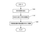
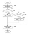
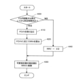
- 5 is a flowchart showing the contents of power supply control in the first embodiment.
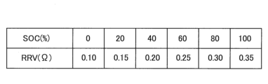
- 4 is a required resistance value map that is referenced to obtain a required resistance value according to a charging rate of a battery in the first embodiment
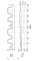
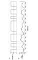
- 5 is a time chart showing (A) the vehicle speed of the electric cart and (B) changes in the charging rate of the battery in the first embodiment.
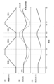
- 5 is a time chart showing changes in (A) vehicle speed of an electric cart, (B) charging rate of a battery, and (C) resistance value of a variable resistor in the first embodiment.
- 10 is a flowchart showing the contents of power supply control in the second embodiment.
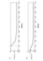
- FIG. 13 is a time chart showing a simplified diagram of changes in (A) charging rate and (B) FC voltage value according to the second embodiment.
- 13 is a time chart showing (A) the resistance value of a variable resistor and (B) the change in the charging rate of a battery in the second embodiment.
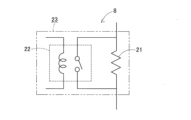
- FIG. 11 is a circuit diagram showing a resistor device according to a modified example of the second embodiment.
- 13 is a flowchart showing the contents of power supply control in the third embodiment.
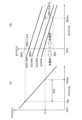
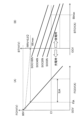
- 13A is a graph showing the current-voltage characteristics of an FC
- FIG. 13B is a graph showing the current-voltage characteristics of a battery according to the third embodiment.
- 13 is a time chart showing changes in (A) an FC current value, (B) an FC voltage value, and (C) a required resistance value according to a third embodiment.
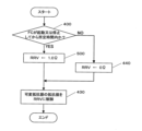
- 13 is a flowchart showing the contents of power supply control in the fourth embodiment.
- 13 is a required resistance value map that is referred to in order to obtain a required resistance value according to an FC voltage value in the fourth embodiment.
- 12A is a graph according to the fourth embodiment, showing current-voltage characteristics of an FC and current-voltage characteristics of a battery, similar to FIG. 11 .
- 13 is a time chart showing the change in (A) FC voltage value and (B) battery voltage value when a variable resistor is set to "0 ⁇ " at the time of starting up the FC in the fourth embodiment.
- 13 is a time chart showing the change in (A) FC voltage value and (B) battery voltage value when a variable resistor is set to "1.0 ⁇ " at the time of starting up the FC in the fourth embodiment. 13 is a flowchart showing the contents of power supply control in the fifth embodiment.
- FIG. 1 First Embodiment First, the first embodiment will be described in detail with reference to FIGS. 1 to 5.
- FIG. 1 is a diagrammatic representation of FIG. 1 to 5.
- FIG. 1 A block diagram of a fuel cell system mounted on an electric cart according to this embodiment is shown in Figure 1.
- This fuel cell system includes a fuel cell (FC) 1, an electric motor 2, a first power line 3 connecting the FC 1 to the motor 2, a battery 4, and a second power line 5 connecting the battery 4 to the first power line 3.
- the second power line 5 is connected to the first power line 3 between a variable resistor 7 and the motor 2.
- FC1 is an electrochemical cell that converts the chemical energy of fuel and oxidizer into electricity through an oxidation-reduction reaction, and has a well-known configuration.
- Motor 2 has a well-known configuration and corresponds to an example of a "load device" in this disclosed technology.
- battery 4 is composed of a chargeable and dischargeable secondary battery.
- the first power line 3 is provided with a rectifying diode 6 and a variable resistor 7 configured to change its resistance value.
- the variable resistor 7 has a well-known configuration that allows the resistance value to be changed steplessly by electrically operating it, and corresponds to an example of a "variable resistance means" in this disclosed technology.
- the fuel cell system further includes an electronic control unit (ECU) 10 for controlling the resistance value of the variable resistor 7.
- the ECU 10 has a well-known configuration including a central processing unit (CPU) that performs arithmetic processing, a memory, input/output ports, etc.
- the ECU 10 corresponds to an example of a "control means" in this disclosed technology.
- the motor 2 is drivingly connected to the driving wheels 11 of the electric cart.
- An accelerator sensor 12 is connected to the ECU 10.
- the accelerator sensor 12 detects the operation angle of a pedal 13 operated by a user of the electric cart as the accelerator opening degree, and outputs the detection signal to the ECU 10.
- the ECU 10 is electrically connected to the battery 4 and monitors the charging rate SOC of the battery 4.
- the ECU 10 also corresponds to an example of the "monitoring means” of this disclosed technology.
- the ECU 10 is also electrically connected to the FC1 and measures the current value of the FC1.
- the ECU 10 also corresponds to an example of the "measuring means" of this disclosed technology.
- the ECU 10 executes the following "power supply control" to ensure that the current value of FC1 falls within the allowable current usage range when the electric cart is being driven.
- FIG. 2 is a flowchart showing an example of the contents of the "power supply control" of this embodiment stored in the memory of the ECU 10.
- FIG. 2 is a flowchart showing an example of the contents of the "power supply control" of this embodiment stored in the memory of the ECU 10.
- step 100 the ECU 10 captures the charging rate SOC of the battery 4 being monitored.
- the ECU 10 calculates the required resistance value RRV according to the input charging rate SOC.
- the ECU 10 determines the required resistance value RRV according to the charging rate SOC, for example, by referring to a required resistance value map as shown in FIG. 3.
- the required resistance value RRV is set so as to bring the charging rate SOC of the battery 4 closer to the median value (50%).
- the required resistance value RRV is set so as to increase within the range of 0.10 to 0.35 ( ⁇ ) as the charging rate SOC increases within the range of 0 to 100 (%).
- step 120 the ECU 10 controls the variable resistor 7 to set the resistance value of the variable resistor 7 to the required resistance value RRV.
- the ECU 10 controls the resistance value of the variable resistor 7 so that the current value of FC1 is within an allowable current usage region. Specifically, in order to bring the charging rate SOC of the battery 4 closer to the median value (50%), the ECU 10 controls the resistance value of the variable resistor 7 to a required resistance value RRV according to the charging rate SOC by controlling the variable resistor 7.
- the ECU 10 controls the variable resistor 7 so that the current value of FC1 is within the allowable current use region, thereby controlling the power supplied from FC1 and the battery 4 to the motor 2. Therefore, the charging rate SOC of the battery 4 is brought close to the median value (50%) without using a voltage transformer, and FC1 is used within the allowable current use region.
- the charging rate SOC of the battery 4 is monitored, a required resistance value RRV corresponding to the charging rate SOC is obtained, and the resistance value of the variable resistor 7 is controlled to the required resistance value RRV.
- the charging rate of the battery 4 can be brought close to the median value (50%) simply by controlling the resistance value of the variable resistor 7 while keeping the output of FC1 as it is.
- the output of the battery 4 can be controlled so as not to exceed the upper limit. Therefore, the power supplied to the motor 2 can be controlled so as not to exceed the upper limit power of the FC 1 and the battery 4 without using a voltage converter, making it possible to provide a simpler and less expensive fuel cell system.
- Figure 4 shows a time chart of (A) the speed of the electric cart and (B) the change in the charging rate SOC of the battery 4.
- the thick line indicates the case where the resistance value of the variable resistor 7 is "0.25 ⁇ ”
- the dashed line indicates the case where the resistance value is "0.50 ⁇ ”
- the two-dot chain line indicates the case where the resistance value is "1.0 ⁇ ”.
- the operation of an electric cart involves cyclical repetition of acceleration, deceleration, and stopping.
- the charging rate SOC can be maintained at "50%” or higher throughout the entire operating time, but when the resistance value is "0.50 ⁇ " or "1.0 ⁇ ", the charging rate SOC falls below "50%" partway through operation.
- FIG. 5 shows a time chart of (A) the speed of the electric cart, (B) the charging rate SOC of the battery 4, and (C) the change in the resistance value of the variable resistor 7.
- A times t1 to t2 and t5 to t6 are during acceleration, when the electric cart is braked and power from the battery 4 is consumed.
- Times t3 to t4 and t7 to t8 are during deceleration, when power is regenerated from the motor 2 to the battery 4.
- the bold line shows this embodiment, and the solid line shows a comparison example in which the power supply control of this embodiment is not performed. As can be seen from FIG.
- the resistance value of the variable resistor 7 is controlled according to the charging rate SOC of the battery 4, so that the charging rate SOC of the battery 4 can be brought closer to "50%" than in the comparison example, regardless of changes in the speed of the electric cart.
- step 200 the ECU 10 acquires the charging rate SOC of the battery 4 being monitored.
- step 210 the ECU 10 determines whether the charging rate SOC is equal to or greater than a predetermined second charging rate C2.
- the second charging rate C2 can be set to, for example, "70%.” If the result of this determination is positive, the ECU 10 proceeds to step 220, and if the result of this determination is negative, the ECU 10 proceeds to step 240.
- step 220 the ECU 10 sets the required resistance value RRV to "1.0 ⁇ ."
- "1.0 ⁇ " corresponds to an example of the "first resistance value” of this disclosed technology.
- step 230 the ECU 10 controls the resistance value of the variable resistor 7 to the required resistance value RRV, and then ends the processing.
- the ECU 10 determines whether the charging rate SOC is equal to or lower than the first charging rate C1.
- the first charging rate C1 can be set to, for example, "30%.” If the result of this determination is positive, the ECU 10 proceeds to step 250, and if the result of this determination is negative, the ECU 10 proceeds to step 230.
- step 250 the ECU 10 sets the required resistance value RRV to "0 ⁇ .” "0 ⁇ " corresponds to an example of the "second resistance value" of this disclosed technology. The ECU 10 then transitions to step 230.
- the ECU 10 controls the variable resistor 7 so that the resistance value becomes "0 ⁇ " when the monitored charging rate SOC becomes equal to or lower than the first charging rate C1 (30%), and controls the variable resistor 7 so that the resistance value becomes "1.0 ⁇ " higher than "0 ⁇ ” when the monitored charging rate SOC becomes equal to or higher than the second charging rate C2 higher than the first charging rate C1.
- FIG 7 shows a time chart of (A) the charging rate SOC of battery 4 and (B) the changes in the FC voltage value FCVV.
- the charging rate SOC increases and decreases within the range of "30 to 70 (%)", and since the resistance value of variable resistor 7 is controlled by the above-mentioned power supply control, the FC voltage value FCVV changes as shown in Figure 7(B).
- the ECU 10 controls the variable resistor 7 according to the monitored charging rate SOC, so that the charging rate SOC is brought close to the median value (50%) and the voltage of FC1 is intermittently controlled to an idle state. Therefore, by controlling the resistance value of the variable resistor 7 according to the charging rate SOC of the battery 4, it is possible to control the power supplied to the motor 2 so as not to exceed the upper limit power of FC1 and the battery 4. It is also possible to prevent a high voltage from being applied to FC1.
- the variable resistor 7 in order to control the charging rate SOC of the battery 4 to near the median value (50%), when the charging rate SOC is equal to or higher than the second charging rate C2 (70%), the variable resistor 7 is controlled so that the resistance value is "1.0 ⁇ ", and when the charging rate SOC is equal to or lower than the first charging rate C1 (30%), the variable resistor 7 is controlled so that the resistance value is "0 ⁇ ".
- the charging rate SOC of the battery 4 can be controlled to near the median value (50%), and by controlling the resistance value of the variable resistor 7 to "1.0 ⁇ ", the FC1 can be put into an idle state. Therefore, the FC1 can be put into an idle state without intermittently stopping the electric cart, and the durability of the parts and stack of the FC1 can be improved.
- Figure 8 shows the change in (A) the resistance value of variable resistor 7 and (B) the charging rate SOC of battery 4 in a time chart.
- (A) the resistance value and (B) the charging rate SOC change as shown in Figure 8 and it can be seen that the charging rate SOC approaches the median value (50%) over time.
- a modified example of the second embodiment will be described with reference to FIG. 9.
- This modified example differs from the second embodiment mainly in the configuration of the variable resistance means.
- a resistance device 8 shown in the circuit diagram of FIG. 9 is provided in the first power line 3 shown in FIG. 1 instead of the variable resistor 7.
- This resistance device 8 includes one resistor-relay circuit 23 including one resistor 21 and one relay 22 connected in parallel to the resistor 21.
- This resistance device 8 is configured to be able to change the resistance value of the resistance device 8 in two stages by opening and closing the one relay 22. That is, the resistance value of the resistance device 8 is set to "1.0 ⁇ " by opening the relay 22, and is changed to "0 ⁇ " by closing the relay 22.
- This resistance device 8 corresponds to an example of the "variable resistance means" of this disclosed technology.
- step 230 in the flowchart of FIG. 6 the resistance value of the resistor device 8 is controlled to the required resistance value RRV by opening and closing one relay 22.
- the ECU 10 controls the opening and closing of the relay 22 of the resistor device 8 according to the charging rate SOC of the monitored battery 4, so that the charging rate SOC is brought close to the median value (50%) and the voltage of FC1 is intermittently controlled to an idle state. Therefore, by controlling the resistance value of the resistor device 8 according to the charging rate SOC of the battery 4, it is possible to control the power supplied to the motor 2 so as not to exceed the upper limit power of FC1 and the battery 4. It is also possible to prevent a high voltage from being applied to FC1.
- FIG. 10 is a flow chart showing the content of the "power supply control" in this embodiment.
- step 300 the ECU 10 captures the measured FC1 current value (FC current value FCCV).
- step 310 the ECU 10 determines whether the FC current value FCCV is equal to or greater than a first predetermined value B1.
- the first predetermined value B1 means the high current value in the current usage range of FC1, and can be, for example, "40A.” If the result of this determination is positive, the ECU 10 proceeds to step 320, and if the result of this determination is negative, the ECU 10 proceeds to step 340.
- step 320 the ECU 10 sets the required resistance value RRV to "0.25 ⁇ .”
- This required resistance value RRV represents a low resistance value that is equal to or exceeds the voltage usage range of the battery 4.
- step 330 the ECU 10 controls the resistance value of the variable resistor 7 to the required resistance value RRV, and then ends the processing.
- step 340 it is determined whether the FC current value FCCV is less than a second predetermined value B2.
- the second predetermined value B2 may be, for example, "10 A.” If the result of this determination is positive, the ECU 10 proceeds to step 350, and if the result of this determination is negative, the ECU 10 proceeds to step 360.
- step 350 the ECU 10 sets the required resistance value RRV to "1.0 ⁇ .”
- This required resistance value RRV means a high resistance value that is below the voltage usage region of the battery 4. After that, the ECU 10 transitions to step 330.
- step 360 the ECU 10 sets the required resistance value RRV to "0.5 ⁇ " and then proceeds to step 330.
- the ECU 10 controls the variable resistor 7 to lower the resistance value of the variable resistor 7 so that it is equal to or higher than the voltage usage range of the battery 4, and when the measured FC current value FCCV is on the low current side of the current usage range of FC1, the ECU 10 controls the variable resistor 7 to raise the resistance value of the variable resistor 7 so that it is lower than the voltage usage range of the battery 4 or so that FC1 avoids high voltage when the measured FC current value FCCV is on the low current side of the current usage range of FC1.
- FIG. 11 shows graphs of (A) the current-voltage characteristics of FC1 and (B) the current-voltage characteristics of battery 4.
- FC1 is set to have a current usage area IUA between a high-voltage avoidance current value FIA (e.g., 5A) and a maximum current value FImax (e.g., 50A).
- battery 4 is used between a minimum voltage value BEL (e.g., 38V) and a maximum voltage value BEH (e.g., 42V) with a high-voltage avoidance voltage value BEA set to, for example, 50V.
- the maximum voltage value BEH is on the line for a charging rate SOC of 100%
- the minimum voltage value BEL is on the line for a charging rate SOC of 0%.
- the ECU 10 when the FC current value FCCV is high (e.g., 40 A), the ECU 10 sets the required resistance value RRV to 0.25 ⁇ so that the FC current value FCCV does not reach its maximum current value FImax.
- the FC current value FCCV is low (e.g., 10 A)
- the ECU 10 sets the required resistance value RRV to 1.0 ⁇ to prevent FC1 from becoming a high voltage.
- the ECU 10 controls the variable resistor 7 according to the current value of FC1 measured, so that the current value of FC1 approaches its current usage range. Therefore, by controlling the resistance value of the variable resistor 7 according to the current value of FC1, it is possible to control the power supplied to the motor 2 so as not to exceed the upper limit power of FC1 and the battery 4. It is also possible to prevent a high voltage from being applied to FC1.
- FIG. 12 shows a time chart of the changes in (A) FC current value FCCV, (B) FC voltage value FCVV, and (C) required resistance value RRV.
- FC1 can be used within its current usage range IUA (5 to 50 (A)) by changing the required resistance value RRV between "0.25 ⁇ ", “0.5 ⁇ ", and "1.0 ⁇ " in response to changes in the FC current value FCCV.
- a modified example of the third embodiment differs from the third embodiment mainly in the configuration of the variable resistance means.
- a resistance device 8 instead of the variable resistor 7, a resistance device 8 having three resistor-relay circuits 23 shown in FIG. 9 connected in series is provided on the first power line 3 shown in FIG. 1.
- This resistance device 8 is configured so that the resistance value of the resistance device 8 can be changed in three stages by selectively opening and closing three relays 22.
- the resistance value is set to "1.0 ⁇ " by opening all of the relays 22 of the three resistor-relay circuits 23, the resistance value is set to "0.5 ⁇ " by opening two of the three resistor-relay circuits 23, and the resistance value is set to "0.25 ⁇ " by opening one of the three relays 22 of the three resistor-relay circuits 23.
- the resistance value of the resistor device 8 is controlled to the required resistance value RRV by selectively opening and closing three relays 22.
- the ECU 10 controls the resistance device 8 according to the measured current value of FC1, so that the current value of FC1 approaches its current usage range. Therefore, by controlling the resistance value of the resistance device 8 according to the current value of FC1, it is possible to control the power supplied to the motor 2 so as not to exceed the upper limit power of FC1 and the battery 4. It is also possible to prevent a high voltage from being applied to FC1.
- FIG. 13 is a flow chart showing the content of the "power supply control" in this embodiment.
- step 400 ECU 10 determines whether or not a predetermined time has elapsed since FC1 was started or stopped.
- the predetermined time can be, for example, "3 seconds.” If the result of this determination is positive, ECU 10 transitions processing to step 410, and if the result of this determination is negative, ECU 10 transitions processing to step 440.
- step 410 the ECU 10 acquires the measured FC voltage value FCVV.
- the ECU 10 calculates the required resistance value RRV according to the FC voltage value FCVV.
- the ECU 10 determines the required resistance value RRV according to the FC voltage value FCVV, for example, by referring to the required resistance value map shown in FIG. 14.
- This required resistance value map sets the required resistance value RRV that brings the charging rate SOC of the battery 4 closer to the median value (50%).
- the required resistance value RRV is set to be higher in the range of "0.01 to 0.30 ( ⁇ )" as the FC voltage value FCVV becomes higher in the range of "50 to 80 (V)" so that it is equal to or lower than the maximum voltage value of the battery 4.
- step 430 the ECU 10 controls the resistance value of the variable resistor 7 to the required resistance value RRV, and then ends the processing.
- step 400 moving from step 400 to step 440, the ECU 10 sets the required resistance value RRV to "0 ⁇ " and transitions to step 430.
- the ECU 10 controls the variable resistor 7 to lower its resistance value so that the voltage of the battery 4 is equal to or lower than the maximum voltage of the battery 4 or so that the FC1 is prevented from being at a high voltage, depending on the FC voltage value FCVV measured at a predetermined time when the FC1 is started or stopped.
- FIG. 15 (A) the current-voltage characteristics of FC1 and (B) the current-voltage characteristics of battery 4 are shown in a graph similar to FIG. 11.
- ECU 10 sets the required resistance value RRV according to the FC voltage value FCVV within a predetermined time at start-up or stop so that the voltage of battery 4 does not exceed the maximum voltage value BEmax.
- the ECU 10 controls the variable resistor 7 according to the measured current value of the FC1, thereby suppressing the voltage of the battery 4 so as not to exceed its upper limit. Therefore, by controlling the resistance value of the variable resistor 7 according to the current value of the FC1, it is possible to control the power supplied to the motor 2 so as not to exceed the upper limit power of the FC1 and the battery 4. It is also possible to suppress the application of a high voltage to the FC1.
- Figure 16 shows, in a time chart, the changes in (A) the FC voltage value FCVV and (B) the battery voltage value BTVV when the variable resistor 7 is "0 ⁇ " (no resistance) when FC1 is started.
- Figure 17 shows, in a time chart, the changes in (A) the FC voltage value FCVV and (B) the battery voltage value BTVV when the variable resistor 7 is "1.0 ⁇ " when FC1 is started.
- a modified example of the fourth embodiment differs from the fourth embodiment mainly in the configuration of the variable resistance means.
- a resistance device 8 having four resistor-relay circuits 23 shown in FIG. 9 connected in series is provided on the first power line 3 shown in FIG. 1.
- This resistance device 8 is configured to be able to change the resistance value of the resistance device 8 in four stages by selectively opening and closing four relays 22.
- the resistance value is set to "0.30 ⁇ " by opening all of the relays 22 of the four resistor-relay circuits 23, the resistance value is set to "0.20 ⁇ " by opening three of the four relays 22 of the four resistor-relay circuits 23, the resistance value is set to "0.10 ⁇ ” by opening two of the four relays 22 of the four resistor-relay circuits 23, the resistance value is set to "0.01 ⁇ ” by opening one of the four relays 22 of the four resistor-relay circuits 23, and the resistance value is set to "0 ⁇ " by closing all of the relays 22 of the four resistor-relay circuits 23.
- step 430 in the flowchart of FIG. 13 the resistance value of the resistor device 8 is controlled to the required resistance value RRV by selectively opening and closing four relays 22.
- FIG. 18 shows the content of the "power supply control" in this embodiment in the form of a flowchart.
- the flowchart in Figure 18 differs in that step 410 in the flowchart in Figure 13 is omitted, and step 420 is changed to processing in step 500. That is, in step 500, the ECU 10 sets the required resistance value RRV to "1.0 ⁇ ".
- the ECU 10 controls the variable resistor 7 to increase its resistance to 1.0 ⁇ so that the voltage of the battery 4 does not exceed the upper limit within a specified time when the FC1 is started or stopped.
- step 430 in the flowchart of FIG. 18 the resistance value of the resistor device 8 is controlled to the required resistance value RRV by opening and closing one relay 22.
- variable resistor 7 or a resistance device 8 is provided on the first power line 3 (FC1 side), but a variable resistor or a resistance device can also be provided on the second power line (battery side).
- an electric motor 2 is used as the load device, but other electric motors may also be used.
- a resistance device 8 including a resistor-relay circuit 23 including a resistor 21 and a relay 22 connected in parallel to the resistor 21 is provided on the first power line 3, and the resistance value of the resistance device 8 can be changed in two stages by opening and closing the relay 22.
- a resistance device including a resistor and a relay connected in parallel to the resistor, connected in series can be provided on the first power line, and the resistance value of the resistance device can be changed in multiple stages by selectively opening and closing the relays.
- the ECU when the monitored charging rate becomes equal to or lower than a predetermined first charging rate, the ECU opens at least one relay so that the resistance value becomes the predetermined first resistance value, and when the monitored charging rate becomes equal to or higher than a second charging rate higher than the first charging rate, the ECU opens at least one more relay than when the charging rate is equal to or lower than the first charging rate so that the resistance value becomes the predetermined second resistance value lower than the first resistance value.
- the disclosed technology can be used in fuel cell systems installed in electric vehicles.
- FC Fluel Cell
- Motor Motor (load device) 3 First power line
- Battery Second power line
- Variable resistor variable resistance means
- Resistance device variable resistance means
- ECU control means, monitoring means, measuring means
- resistor 22 relay resistor-relay circuit
Landscapes
- Engineering & Computer Science (AREA)
- Sustainable Energy (AREA)
- Life Sciences & Earth Sciences (AREA)
- Sustainable Development (AREA)
- Chemical Kinetics & Catalysis (AREA)
- Chemical & Material Sciences (AREA)
- Electrochemistry (AREA)
- General Chemical & Material Sciences (AREA)
- Manufacturing & Machinery (AREA)
- Power Engineering (AREA)
- Transportation (AREA)
- Mechanical Engineering (AREA)
- Fuel Cell (AREA)
Abstract
燃料電池システムは、FC(1)と、モータ(2)と、FC(1)とモータ(2)を接続する第1電力線(3)と、バッテリ(4)と、バッテリ(4)と第1電力線(3)を接続する第2電力線(5)と、第1電力線(3)に設けられ、抵抗値を変更可能に構成した可変抵抗器(7)と、FC(1)の電流値が許容される電流使用領域となるように可変抵抗器(7)の抵抗値を制御するECU(10)とを備える。
Description
この明細書に開示される技術は、電気自動車等の電源として使用され、負荷装置に接続される燃料電池と、燃料電池から負荷装置に至る放電経路に設けられ、燃料電池と並列に接続されるバッテリとを備えた燃料電池システムに関する。
従来、この種の技術として、例えば、下記の特許文献1に記載される「燃料電池システム」が知られている。このシステムは、燃料電池と、負荷装置と、燃料電池と負荷装置を接続する第1配線と、バッテリと、バッテリから第1配線に接続される第2配線とを備える。第1配線には、燃料電池の端子間電圧と負荷装置側の電圧との間で電圧変換を行う電圧変換器が設けられる。
ところが、特許文献1に記載の燃料電池システムでは、電圧変換器は、燃料電池の上限電力を超えないように負荷装置への供給電力を制御できるものの、それ自体がシステムのコストアップ及び大型化につながる懸念があった。近年では、電気自動車等に搭載される燃料電池システムとして、簡易で安価なシステムが要望されている。
この開示技術は、上記事情に鑑みてなされたものであって、その目的は、電圧変換器を使用することなく燃料電池及びバッテリの上限電力を超えないように負荷装置へ供給される電力の制御を可能とし、簡易でより安価な燃料電池システムを提供することにある。
(1)上記目的を達成するために、本開示技術の一態様は、燃料電池と、負荷装置と、燃料電池と負荷装置を接続する第1電力線と、バッテリと、バッテリと第1電力線を接続する第2電力線とを備えた燃料電池システムにおいて、第1電力線又は第2電力線に設けられ、抵抗値を変更可能に構成した可変抵抗手段と、燃料電池の電流値が許容される電流使用領域となるように可変抵抗手段の抵抗値を制御するための制御手段とを備えたことを趣旨とする。
上記(1)の構成によれば、燃料電池の電流値が許容される電流使用領域となるように制御手段が可変抵抗手段を制御することにより、 燃料電池とバッテリから負荷装置への供給電力が制御される。従って、電圧変圧器を使用することなく、バッテリの充電率が中央値に近付けられ、かつ、燃料電池が許容される電流使用領域で使用される。
(2)上記目的を達成するために、上記(1)の構成において、可変抵抗手段は、抵抗値を変更可能に構成した可変抵抗器であることが好ましい。
上記(2)の構成によれば、可変抵抗手段を可変抵抗器にすることで、上記(1)の構成と同等の作用が得られる。
(3)上記目的を達成するために、上記(1)の構成において、可変抵抗手段は、一つの抵抗器と、その抵抗器に並列に接続された一つのリレーとを含む抵抗器・リレー回路を少なくとも一つ備え、少なくとも一つのリレーを開閉することにより抵抗値を多段階に変更可能に構成した抵抗装置であることが好ましい。
上記(3)の構成によれば、可変抵抗手段を抵抗装置にすることで、上記(1)の構成と同等の作用が得られる。
(4)上記目的を達成するために、上記(2)の構成において、バッテリの充電率を監視するための監視手段を更に備え、制御手段は、監視される充電率が所定の第1充電率以下になったときは、抵抗値が所定の第1抵抗値となるように可変抵抗器を制御し、監視される充電率が第1充電率より高い第2充電率以上になったときは、抵抗値が第1抵抗値より高い所定の第2抵抗値となるように可変抵抗器を制御することが好ましい。
上記(4)の構成によれば、上記(2)の構成の作用に加え、制御手段が監視されるバッテリの充電率に応じて可変抵抗器を制御することにより、その充電率がほぼ中央値に近付けられ、燃料電池の電圧が間欠的にアイドル状態に制御される。
(5)上記目的を達成するために、上記(3)の構成において、バッテリの充電率を監視するための監視手段を更に備え、制御手段は、監視される充電率が所定の第1充電率以下になったときは、抵抗値が所定の第1抵抗値となるように少なくとも一つのリレーを開に制御し、監視される充電率が第1充電率より高い第2充電率以上になったときは、抵抗値が第1抵抗値より低い所定の第2抵抗値となるように第1充電率以下の際より少なくとも一つ以上多いリレーを開制御することが好ましい。
上記(5)の構成によれば、上記(3)の構成の作用に加え、制御手段が監視されるバッテリの充電率に応じて抵抗装置を制御することにより、その充電率がほぼ中央値に近付けられ、燃料電池の電圧が間欠的にアイドル状態に制御される。
(6)上記目的を達成するために、上記(2)の構成において、燃料電池の電流値を測定するための測定手段を更に備え、制御手段は、測定される電流値が燃料電池の電流使用領域における高電流側の値となるときは、バッテリの電圧値の許容される電圧使用領域上となるように可変抵抗器の抵抗値を下げるように可変抵抗器を制御し、測定される電流値が燃料電池の電流使用領域における低電流側の値となるときは、バッテリの電圧値の電圧使用領域未満又は燃料電池が高電圧回避となるように可変抵抗器の抵抗値を上げるように可変抵抗器を制御することが好ましい。
上記(6)の構成によれば、上記(2)の構成の作用に加え、制御手段が測定される燃料電池の電流値に応じて可変抵抗器を制御することにより、燃料電池の電流値がその電流使用領域に近付けられる。
(7)上記目的を達成するために、上記(3)の構成において、燃料電池の電流値を測定するための測定手段を更に備え、制御手段は、測定される電流値が燃料電池の電流使用領域における高電流側の値となるときは、抵抗装置の抵抗値が低くなるように少なくとも一つのリレーを閉に制御し、測定される電流値が燃料電池の電流使用領域における低電流側の値となるときは、抵抗装置の抵抗値が高くなるように少なくとも一つのリレーを開に制御することが好ましい。
上記(7)の構成によれば、上記(3)の構成の作用に加え、制御手段が、測定される燃料電池の電流値に応じて抵抗装置の少なくとも一つのリレーを制御することにより、燃料電池の電流値がその電流使用領域に近付けられる。
(8)上記目的を達成するために、上記(2)の構成において、燃料電池の電流値を測定するための測定手段を更に備え、制御手段は、燃料電池の起動時又は停止時における所定時間に測定される電流値に応じてバッテリの最大電圧値以下又は燃料電池が高電圧回避となるように可変抵抗器の抵抗値を制御することが好ましい。
上記(8)の構成によれば、上記(2)の構成の作用に加え、燃料電池の起動時又は停止時に、制御手段が、測定される燃料電池の電流値に応じて可変抵抗器を制御することにより、バッテリの電圧がその上限値を超えないように抑えられる。
(9)上記目的を達成するために、上記(3)の構成において、燃料電池の電流値を測定するための測定手段を更に備え、制御手段は、燃料電池の起動時又は停止時における所定時間に測定される電流値がバッテリの最大電流値を超えている場合又は燃料電池が高電圧回避する場合は、抵抗値が高くなるように少なくとも一つのリレーを開に制御することが好ましい。
上記(8)の構成によれば、上記(3)の構成の作用に加え、燃料電池の起動時又は停止時に、制御手段が、測定される燃料電池の電流値に応じて抵抗装置の少なくとも一つのリレーを制御することにより、バッテリの電圧がその上限値を超えないように抑えられる。
上記(1)の構成によれば、電圧変換器を使用することなく燃料電池及びバッテリの上限電力を超えないように負荷装置へ供給される電力を制御することができ、簡易でより安価な燃料電池システムを提供することができる。
上記(2)の構成によれば、上記(1)の構成と同等の効果を得ることができる。
上記(3)の構成によれば、上記(1)の構成と同等の効果を得ることができる。
上記(4)の構成によれば、上記(2)の構成の効果に加え、バッテリの充電率に応じて可変抵抗器の抵抗値を制御することで、燃料電池及びバッテリの上限電力を超えないように負荷装置への供給電力を制御することができる。また、燃料電池に高電圧がかかることを抑制することができる。
上記(5)の構成によれば、上記(3)の構成の効果に加え、バッテリの充電率に応じて抵抗装置の抵抗値を制御することで、燃料電池及びバッテリの上限電力を超えないように負荷装置への供給電力を制御することができる。また、燃料電池に高電圧がかかることを抑制することができる。
上記(6)の構成によれば、上記(2)の構成の効果に加え、燃料電池の電流値に応じて可変抵抗器の抵抗値を制御することで、燃料電池及びバッテリの上限電力を超えないように負荷装置への供給電力を制御することができる。また、燃料電池に高電圧がかかることを抑制することができる。
上記(7)の構成によれば、上記(3)の構成の効果に加え、燃料電池の電流値に応じて抵抗装置の抵抗値を制御することで、燃料電池及びバッテリの上限電力を超えないように負荷装置への供給電力を制御することができる。また、燃料電池に高電圧がかかることを抑制することができる。
上記(8)の構成によれば、上記(2)の構成の効果に加え、燃料電池の電流値に応じて可変抵抗器の抵抗値を制御することで、燃料電池及びバッテリの上限電力を超えないように負荷装置への供給電力を制御することができる。また、燃料電池に高電圧がかかることを抑制することができる。
上記(9)の構成によれば、上記(3)の構成の効果に加え、燃料電池の電流値に応じて抵抗装置の抵抗値を制御することで、燃料電池及びバッテリの上限電力を超えないように負荷装置への供給電力を制御することができる。また、燃料電池に高電圧がかかることを抑制することができる。
以下、燃料電池システムを小型電気自動車(電動カート)に具体化したいくつかの実施形態につき図面を参照して詳細に説明する。
<第1実施形態>
先ず、第1実施形態について図1~図5を参照して詳細に説明する。
先ず、第1実施形態について図1~図5を参照して詳細に説明する。
[燃料電池システムの概要]
図1に、この実施形態の電動カートに搭載された燃料電池システムをブロック図により示す。この燃料電池システムは、燃料電池(FC)1と、電動式のモータ2と、FC1とモータ2を接続する第1電力線3と、バッテリ4と、バッテリ4と第1電力線3を接続する第2電力線5とを備える。第2電力線5は、可変抵抗器7とモータ2との間の第1電力線3に接続される。
図1に、この実施形態の電動カートに搭載された燃料電池システムをブロック図により示す。この燃料電池システムは、燃料電池(FC)1と、電動式のモータ2と、FC1とモータ2を接続する第1電力線3と、バッテリ4と、バッテリ4と第1電力線3を接続する第2電力線5とを備える。第2電力線5は、可変抵抗器7とモータ2との間の第1電力線3に接続される。
FC1は、燃料と酸化剤の化学エネルギーを、酸化還元反応により電気に変換する電気化学電池であり、周知の構成を備える。モータ2は、周知の構成を備え、この開示技術の「負荷装置」の一例に相当する。バッテリ4は、この実施形態では、充放電可能な二次電池により構成される。
この実施形態において、第1電力線3には、整流用のダイオード6と、抵抗値を変更可能に構成した可変抵抗器7が設けられる。可変抵抗器7は、電気的に動作させることで抵抗値を無段階に変更可能な周知の構成を有し、この開示技術の「可変抵抗手段」の一例に相当する。燃料電池システムは、可変抵抗器7の抵抗値を制御するための電子制御装置(ECU)10を更に備える。ECU10は、演算処理を行う中央処理装置(CPU)、メモリ及び入出力ポート等を含む周知の構成を備える。ECU10は、この開示技術の「制御手段」の一例に相当する。
この実施形態において、モータ2は、電動カートの駆動輪11に駆動連結される。ECU10にはアクセルセンサ12が接続される。アクセルセンサ12は、電動カートのユーザが操作するペダル13の操作角度をアクセル開度として検出し、その検出信号をECU10へ出力するようになっている。
ECU10はバッテリ4に対し電気的に接続され、バッテリ4の充電率SOCを監視するようになっている。ECU10は、この開示技術の「監視手段」の一例にも相当する。また、ECU10はFC1に対し電気的に接続され、FC1の電流値を測定するようになっている。ECU10は、この開示技術の「測定手段」の一例にも相当する。
ここで、FC1の電流値は、FC1の耐久性を考慮すると、少な過ぎても多過ぎても好ましくなく、許容される電流使用領域の範囲で使用する必要がある。そこで、この実施形態で、ECU10は、電動カートの運転時に、FC1の電流値が許容される電流使用領域となるようにするために、次のような「電力供給制御」を実行するようになっている。
[電力供給制御について]
図2に、ECU10のメモリに格納されたこの実施形態の「電力供給制御」の内容の一例をフローチャートにより示す。
図2に、ECU10のメモリに格納されたこの実施形態の「電力供給制御」の内容の一例をフローチャートにより示す。
処理がこのルーチンへ移行すると、ステップ100で、ECU10は、監視しているバッテリ4の充電率SOCを取り込む。
次に、ステップ110で、ECU10は、取り込まれた充電率SOCに応じて要求抵抗値RRVを算出する。ECU10は、例えば、図3に示すような要求抵抗値マップを参照することにより、充電率SOCに応じた要求抵抗値RRVを求める。この要求抵抗値マップは、バッテリ4の充電率SOCを中央値(50%)に近付けるように要求抵抗値RRVが設定されている。すなわち、充電率SOCが「0~100(%)」の範囲で高くなるほど、要求抵抗値RRVは「0.10~0.35(Ω)」の範囲で高くなるように設定される。
そして、ステップ120で、ECU10、可変抵抗器7を制御することにより、可変抵抗器7の抵抗値を要求抵抗値RRVに制御する。
上記電力供給制御によれば、ECU10は、FC1の電流値が許容される電流使用領域となるように可変抵抗器7の抵抗値を制御するようになっている。具体的には、ECU10は、バッテリ4の充電率SOCを中央値(50%)に近付けるために、可変抵抗器7を制御することで、可変抵抗器7の抵抗値を充電率SOCに応じた要求抵抗値RRVに制御するようになっている。
[燃料電池システムの作用及び効果について]
以上説明したこの実施形態の燃料電池システムの構成によれば、FC1の電流値が許容される電流使用領域となるようにECU10により可変抵抗器7を制御することにより、 FC1とバッテリ4からモータ2への供給電力が制御される。従って、電圧変圧器を使用することなく、バッテリ4の充電率SOCが中央値(50%)に近付けられ、かつ、FC1が許容される電流使用領域で使用される。この実施形態によれば、バッテリ4の充電率SOCを中央値(50%)に近付けるために、バッテリ4の充電率SOCを監視し、その充電率SOCに応じた要求抵抗値RRVを求め、可変抵抗器7の抵抗値を要求抵抗値RRVに制御する。従って、電動カートの運転状態にかかわらず、FC1の出力を成り行きとし、可変抵抗器7の抵抗値を制御するだけで、バッテリ4の充電率を中央値(50%)に近付けることができる。また、バッテリ4の出力が上限を超えないように制御することができる。このため、電圧変換器を使用することなく、FC1及びバッテリ4の上限電力を超えないようにモータ2へ供給される電力を制御することができ、簡易でより安価な燃料電池システムを提供することができる。
以上説明したこの実施形態の燃料電池システムの構成によれば、FC1の電流値が許容される電流使用領域となるようにECU10により可変抵抗器7を制御することにより、 FC1とバッテリ4からモータ2への供給電力が制御される。従って、電圧変圧器を使用することなく、バッテリ4の充電率SOCが中央値(50%)に近付けられ、かつ、FC1が許容される電流使用領域で使用される。この実施形態によれば、バッテリ4の充電率SOCを中央値(50%)に近付けるために、バッテリ4の充電率SOCを監視し、その充電率SOCに応じた要求抵抗値RRVを求め、可変抵抗器7の抵抗値を要求抵抗値RRVに制御する。従って、電動カートの運転状態にかかわらず、FC1の出力を成り行きとし、可変抵抗器7の抵抗値を制御するだけで、バッテリ4の充電率を中央値(50%)に近付けることができる。また、バッテリ4の出力が上限を超えないように制御することができる。このため、電圧変換器を使用することなく、FC1及びバッテリ4の上限電力を超えないようにモータ2へ供給される電力を制御することができ、簡易でより安価な燃料電池システムを提供することができる。
図4には、(A)電動カートの車速と(B)バッテリ4の充電率SOCの変化をタイムチャートにより示す。(B)において、太線は可変抵抗器7の抵抗値が「0.25Ω」の場合を示し、破線はその抵抗値が「0.50Ω」の場合を示し、2点鎖線はその抵抗値が「1.0Ω」の場合を示す。
図4(A)に示すように、電動カートの運転は、加速、減速及び停止を周期的に繰り返すように行われる。このとき、図4(B)に示すように、抵抗値が「0.25Ω」の場合は、全運転時間にわたって充電率SOCを「50%」以上に保てるが、抵抗値が「0.50Ω」及び「1.0Ω」の場合は、運転開始後の途中から充電率SOCが「50%」を下回ることがわかる。
図5には、(A)電動カートの車速、(B)バッテリ4の充電率SOC及び(C)可変抵抗器7の抵抗値の変化をタイムチャートにより示す。(A)において、時刻t1~t2,t5~t6は加速時であり、電動カートの制動が行われ、バッテリ4の電力が消費される。時刻t3~t4,t7~t8は減速時であり、モータ2からバッテリ4へ電力の回生が行われる。(B)において、太線は本実施形態を示し、実線は本実施形態の電力供給制御を行わない対比例を示す。図5からわかるように、本実施形態では、バッテリ4の充電率SOCに応じて可変抵抗器7の抵抗値を制御しているので、電動カートの車速の変化にかかわらず、バッテリ4の充電率SOCを対比例よりも「50%」に近付けられることがわかる。
<第2実施形態>
次に、第2実施形態について図6~図8を参照して詳細に説明する。なお、以下の説明において、第1実施形態と同等の構成要素については、同一の符号を付して説明を省略し、異なった点を中心に説明する。
次に、第2実施形態について図6~図8を参照して詳細に説明する。なお、以下の説明において、第1実施形態と同等の構成要素については、同一の符号を付して説明を省略し、異なった点を中心に説明する。
[電力供給制御について]
この実施形態では、電力供給制御の内容の点で第1実施形態と異なる。この実施形態では、バッテリ4の充電率SOCを中央値(50%)付近に制御するために、次のような「電力供給制御」を実行する。図6に、この実施形態の「電力供給制御」の内容をフローチャートにより示す。
この実施形態では、電力供給制御の内容の点で第1実施形態と異なる。この実施形態では、バッテリ4の充電率SOCを中央値(50%)付近に制御するために、次のような「電力供給制御」を実行する。図6に、この実施形態の「電力供給制御」の内容をフローチャートにより示す。
処理がこのルーチンへ移行すると、ステップ200で、ECU10は、監視しているバッテリ4の充電率SOCを取り込む。
次に、ステップ210で、ECU10は、充電率SOCが所定の第2充電率C2以上か否かを判断する。ここで、第2充電率C2を例えば「70%」とすることができる。ECU10は、この判断結果が肯定の場合は処理をステップ220へ移行し、この判断結果が否定の場合は処理をステップ240へ移行する。
ステップ220では、ECU10は、要求抵抗値RRVを「1.0Ω」に設定する。「1.0Ω」は、この開示技術の「第1抵抗値」の一例に相当する。
次に、ステップ230では、ECU10は、可変抵抗器7の抵抗値を要求抵抗値RRVに制御し、その後の処理を終了する。
一方、ステップ210から移行してステップ240では、ECU10は、充電率SOCが第1充電率C1以下か否かを判断する。ここで、第1充電率C1を、例えば「30%」とすることができる。ECU10は、この判断結果が肯定の場合は処理をステップ250へ移行し、この判断結果が否定の場合は処理をステップ230へ移行する。
ステップ250では、ECU10は、要求抵抗値RRVを「0Ω」に設定する。「0Ω」は、この開示技術の「第2抵抗値」の一例に相当する。ECU10は、その後、処理をステップ230へ移行する。
上記電力供給制御によれば、ECU10は、バッテリ4の充電率SOCを中央値(50%)付近に制御するために、監視される充電率SOCが第1充電率C1(30%)以下になったときは、抵抗値が「0Ω」となるように可変抵抗器7を制御し、監視される充電率SOCが第1充電率C1より高い第2充電率C2以上になったときは、抵抗値が「0Ω」より高い「1.0Ω」となるように可変抵抗器7を制御するようになっている。
図7に、(A)バッテリ4の充電率SOCと(B)FC電圧値FCVVの変化をタイムチャートにより示す。この実施形態では、図7(A)に示すように、充電率SOCは、「30~70(%)」の範囲で増減し、上記電力供給制御により可変抵抗器7の抵抗値が制御されることから、FC電圧値FCVVは図7(B)に示すように変化することになる。
[燃料電池システムの作用及び効果について]
以上説明したこの実施形態の燃料電池システムの構成によれば、第1実施形態と同等の作用及び効果を得ることができる。また、この実施形態によれば、ECU10が、監視される充電率SOCに応じて可変抵抗器7を制御することにより、その充電率SOCがほぼ中央値(50%)に近付けられ、FC1の電圧が間欠的にアイドル状態に制御される。このため、バッテリ4の充電率SOCに応じて可変抵抗器7の抵抗値を制御することで、FC1及びバッテリ4の上限電力を超えないようにモータ2への供給電力を制御することができる。また、FC1に高電圧がかかることを抑制することができる。
以上説明したこの実施形態の燃料電池システムの構成によれば、第1実施形態と同等の作用及び効果を得ることができる。また、この実施形態によれば、ECU10が、監視される充電率SOCに応じて可変抵抗器7を制御することにより、その充電率SOCがほぼ中央値(50%)に近付けられ、FC1の電圧が間欠的にアイドル状態に制御される。このため、バッテリ4の充電率SOCに応じて可変抵抗器7の抵抗値を制御することで、FC1及びバッテリ4の上限電力を超えないようにモータ2への供給電力を制御することができる。また、FC1に高電圧がかかることを抑制することができる。
この実施形態の構成によれば、バッテリ4の充電率SOCを中央値(50%)付近に制御するために、充電率SOCが第2充電率C2(70%)以上になったときは、抵抗値が「1.0Ω」となるように可変抵抗器7が制御され、充電率SOCが第1充電率C1(30%)以下となったときは、抵抗値が「0Ω」となるように可変抵抗器7が制御される。この結果、バッテリ4の充電率SOCを中央値(50%)付近に制御することができ、可変抵抗器7の抵抗値を「1.0Ω」に制御することで、FC1をアイドル状態にすることができる。このため、電動カートを間欠停止させることなくFC1をアイドル状態にすることができ、FC1の部品やスタックの耐久性を向上させることができる。
上記電力供給制御により得られる効果を図8に示す。図8には、(A)可変抵抗器7の抵抗値と(B)バッテリ4の充電率SOCの変化をタイムチャートにより示す。図8からわかるように、上記のように可変抵抗器7の抵抗値を制御することで、図8に示すように、(A)抵抗値と(B)充電率SOCが変化し、充電率SOCが時間経過に伴って中央値(50%)に近付けられることがわかる。
<第2実施形態の変形例>
次に、第2実施形態の変形例について図9を参照して説明する。この変形例では、主として可変抵抗手段の構成の点で第2実施形態と異なる。この変形例では、図1に示す第1電力線3には、可変抵抗器7の代わりに、図9に回路図で示す抵抗装置8が設けられる。この抵抗装置8は、一つの抵抗器21と、その抵抗器21に並列に接続された一つのリレー22とを含む抵抗器・リレー回路23を一つ備える。この抵抗装置8は、一つのリレー22を開閉することにより、抵抗装置8の抵抗値を二段階に変更可能に構成される。すなわち、リレー22を開くことで抵抗装置8の抵抗値を「1.0Ω」にし、リレー22を閉じることで抵抗装置8の抵抗値を「0Ω」に変更するように構成される。この抵抗装置8は、この開示技術の「可変抵抗手段」の一例に相当する。
次に、第2実施形態の変形例について図9を参照して説明する。この変形例では、主として可変抵抗手段の構成の点で第2実施形態と異なる。この変形例では、図1に示す第1電力線3には、可変抵抗器7の代わりに、図9に回路図で示す抵抗装置8が設けられる。この抵抗装置8は、一つの抵抗器21と、その抵抗器21に並列に接続された一つのリレー22とを含む抵抗器・リレー回路23を一つ備える。この抵抗装置8は、一つのリレー22を開閉することにより、抵抗装置8の抵抗値を二段階に変更可能に構成される。すなわち、リレー22を開くことで抵抗装置8の抵抗値を「1.0Ω」にし、リレー22を閉じることで抵抗装置8の抵抗値を「0Ω」に変更するように構成される。この抵抗装置8は、この開示技術の「可変抵抗手段」の一例に相当する。
また、この変形例の「電力供給制御」では、図6のフローチャートのステップ230の代わりに、1つのリレー22を開閉することで、抵抗装置8の抵抗値を要求抵抗値RRVに制御するようになっている。
[燃料電池システムの作用及び効果について]
以上説明したこの変形例の燃料電池システムの構成によれば、第2実施形態と同等の作用及び効果を得ることができる。すなわち、ECU10が、監視されるバッテリ4の充電率SOCに応じて抵抗装置8のリレー22を開閉制御することにより、その充電率SOCがほぼ中央値(50%)に近付けられ、FC1の電圧が間欠的にアイドル状態に制御される。このため、バッテリ4の充電率SOCに応じて抵抗装置8の抵抗値を制御することで、FC1及びバッテリ4の上限電力を超えないようにモータ2への供給電力を制御することができる。また、FC1に高電圧がかかることを抑制することができる。
以上説明したこの変形例の燃料電池システムの構成によれば、第2実施形態と同等の作用及び効果を得ることができる。すなわち、ECU10が、監視されるバッテリ4の充電率SOCに応じて抵抗装置8のリレー22を開閉制御することにより、その充電率SOCがほぼ中央値(50%)に近付けられ、FC1の電圧が間欠的にアイドル状態に制御される。このため、バッテリ4の充電率SOCに応じて抵抗装置8の抵抗値を制御することで、FC1及びバッテリ4の上限電力を超えないようにモータ2への供給電力を制御することができる。また、FC1に高電圧がかかることを抑制することができる。
<第3実施形態>
次に、第3実施形態について図10~図12を参照して詳細に説明する。
次に、第3実施形態について図10~図12を参照して詳細に説明する。
[電力供給制御について]
この実施形態では、電力供給制御の内容の点で前記各実施形態と異なる。図10に、この実施形態の「電力供給制御」の内容をフローチャートにより示す。
この実施形態では、電力供給制御の内容の点で前記各実施形態と異なる。図10に、この実施形態の「電力供給制御」の内容をフローチャートにより示す。
処理がこのルーチンへ移行すると、ステップ300で、ECU10は、測定しているFC1の電流値(FC電流値FCCV)を取り込む。
次に、ステップ310で、ECU10は、FC電流値FCCVが第1所定値B1以上か否かを判断する。第1所定値B1は、FC1の電流使用領域における高電流側の値を意味し、例えば「40A」を採用することができる。ECU10は、この判断結果が肯定の場合は処理をステップ320へ移行し、この判断結果が否定の場合は処理をステップ340へ移行する。
ステップ320では、ECU10は、要求抵抗値RRVを「0.25Ω」に設定する。この要求抵抗値RRVは、バッテリ4の電圧使用領域以上となるようにするための低めの抵抗値を意味する。
次に、ステップ330では、ECU10は、可変抵抗器7の抵抗値を要求抵抗値RRVに制御し、その後の処理を終了する。
一方、ステップ340では、FC電流値FCCVが第2所定値B2未満か否かを判断する。第2所定値B2として、例えば「10A」を採用することができる。ECU10は、この判断結果が肯定の場合は処理をステップ350へ移行し、この判断結果が否定の場合は処理をステップ360へ移行する。
ステップ350では、ECU10は、要求抵抗値RRVを「1.0Ω」に設定する。この要求抵抗値RRVは、バッテリ4の電圧使用領域未満となるようにするための高め抵抗値を意味する。その後、ECU10は、処理をステップ330へ移行する。
一方、ステップ360では、ECU10は、要求抵抗値RRVを「0.5Ω」に設定し、その後、処理をステップ330へ移行する。
上記電力供給制御によれば、ECU10は、測定されるFC電流値FCCVがFC1の電流使用領域における高電流側の値となるときは、バッテリ4の電圧使用領域以上となるように可変抵抗器7の抵抗値を下げるように可変抵抗器7を制御し、測定されるFC電流値FCCVがFC1の電流使用領域における低電流側の値となるときは、バッテリ4の電圧使用領域未満又はFC1が高電圧回避となるように可変抵抗器7の抵抗値を上げるように可変抵抗器7を制御するようになっている。
図11には、(A)FC1の電流-電圧特性と(B)バッテリ4の電流-電圧特性をグラフに示す。図11(A)に示すように、この実施形態では、FC1は、高電圧回避電流値FIA(例えば「5A」)と最大電流値FImax(例えば「50A」)との間を電流使用領域IUAとして設定される。また、図11(B)に示すように、この実施形態では、バッテリ4は、高電圧回避電圧値BEAを、例えば「50V」とし、最低電圧値BEL(例えば「38V」)と最高電圧値BEH(例えば「42V」)との間で使用される。最高電圧値BEHは、充電率SOC「100%」の線上にあり、最低電圧値BELは充電率SOC「0%」の線上にある。
この実施形態では、ECU10は、FC電流値FCCVが、その最大電流値FImaxにならないように、FC電流値FCCVが高いとき(例えば「40A」)は、要求抵抗値RRVを「0.25Ω」に設定し、FC電流値FCCVが低いとき(例えば「10A」)は、FC1が高電圧になることを回避するために、要求抵抗値RRVを「1.0Ω」に設定するのである。
[燃料電池システムの作用及び効果について]
以上説明したこの実施形態の燃料電池システムの構成によれば、第1実施形態の作用及び効果に加え、ECU10が測定されるFC1の電流値に応じて可変抵抗器7を制御することにより、FC1の電流値がその電流使用領域に近付けられる。このため、FC1の電流値に応じて可変抵抗器7の抵抗値を制御することで、FC1及びバッテリ4の上限電力を超えないようにモータ2への供給電力を制御することができる。また、FC1に高電圧がかかることを抑制することができる。
以上説明したこの実施形態の燃料電池システムの構成によれば、第1実施形態の作用及び効果に加え、ECU10が測定されるFC1の電流値に応じて可変抵抗器7を制御することにより、FC1の電流値がその電流使用領域に近付けられる。このため、FC1の電流値に応じて可変抵抗器7の抵抗値を制御することで、FC1及びバッテリ4の上限電力を超えないようにモータ2への供給電力を制御することができる。また、FC1に高電圧がかかることを抑制することができる。
図12には、(A)FC電流値FCCV、(B)FC電圧値FCVV及び(C)要求抵抗値RRVの変化をタイムチャートにより示す。図12(A),(B)において、実線は本実施形態を示し、破線は本実施形態の構成を有しない対比例を示す。この実施形態では、図12に示すように、FC電流値FCCVの変化に応じて要求抵抗値RRVを「0.25Ω」、「0.5Ω」及び「1.0Ω」の間で変更することで、FC1をその電流使用領域IUA(5~50(A))の範囲内で使用できることがわかる。
<第3実施形態の変形例>
次に、第3実施形態の変形例について説明する。この変形例では、主として可変抵抗手段の構成の点で第3実施形態と異なる。この変形例では、図1に示す第1電力線3には、可変抵抗器7の代わりに、図9に示す抵抗器・リレー回路23を3つ直列に接続した抵抗装置8が設けられる。この抵抗装置8は、3つのリレー22を選択的に開閉することにより、抵抗装置8の抵抗値を三段階に変更可能に構成される。すなわち、3つの抵抗器・リレー回路23のリレー22の全てを開くことで抵抗値を「1.0Ω」にし、3つの抵抗器・リレー回路23のうち2つのリレー22を開くことで抵抗値を「0.5Ω」にし、3つの抵抗器・リレー回路23のうち1つのリレー22を開くことで抵抗値を「0.25Ω」にするように構成される。
次に、第3実施形態の変形例について説明する。この変形例では、主として可変抵抗手段の構成の点で第3実施形態と異なる。この変形例では、図1に示す第1電力線3には、可変抵抗器7の代わりに、図9に示す抵抗器・リレー回路23を3つ直列に接続した抵抗装置8が設けられる。この抵抗装置8は、3つのリレー22を選択的に開閉することにより、抵抗装置8の抵抗値を三段階に変更可能に構成される。すなわち、3つの抵抗器・リレー回路23のリレー22の全てを開くことで抵抗値を「1.0Ω」にし、3つの抵抗器・リレー回路23のうち2つのリレー22を開くことで抵抗値を「0.5Ω」にし、3つの抵抗器・リレー回路23のうち1つのリレー22を開くことで抵抗値を「0.25Ω」にするように構成される。
また、この変形例の「電力供給制御」では、図10のフローチャートのステップ330の代わりに、3つのリレー22を選択的に開閉することで、抵抗装置8の抵抗値を要求抵抗値RRVに制御するようになっている。
[燃料電池システムの作用及び効果について]
以上説明したこの変形例の燃料電池システムの構成によれば、第3実施形態と同等の作用及び効果を得ることができる。すなわち、ECU10が、測定されるFC1の電流値に応じて抵抗装置8を制御することにより、FC1の電流値がその電流使用領域に近付けられる。このため、FC1の電流値に応じて抵抗装置8の抵抗値を制御することで、FC1及びバッテリ4の上限電力を超えないようにモータ2への供給電力を制御することができる。また、FC1に高電圧がかかることを抑制することができる。
以上説明したこの変形例の燃料電池システムの構成によれば、第3実施形態と同等の作用及び効果を得ることができる。すなわち、ECU10が、測定されるFC1の電流値に応じて抵抗装置8を制御することにより、FC1の電流値がその電流使用領域に近付けられる。このため、FC1の電流値に応じて抵抗装置8の抵抗値を制御することで、FC1及びバッテリ4の上限電力を超えないようにモータ2への供給電力を制御することができる。また、FC1に高電圧がかかることを抑制することができる。
<第4実施形態>
次に、第4実施形態について図13~図17を参照して詳細に説明する。
次に、第4実施形態について図13~図17を参照して詳細に説明する。
[電力供給制御について]
この実施形態では、電力供給制御の内容の点で前記各実施形態と異なる。図13に、この実施形態の「電力供給制御」の内容をフローチャートにより示す。
この実施形態では、電力供給制御の内容の点で前記各実施形態と異なる。図13に、この実施形態の「電力供給制御」の内容をフローチャートにより示す。
処理がこのルーチンへ移行すると、ステップ400で、ECU10は、FC1が起動又は停止してから所定時間内か否かを判断する。ここで、所定時間として、例えば「3秒」を採用することができる。ECU10は、この判断結果が肯定の場合は処理をステップ410へ移行し、この判断結果が否定の場合は処理をステップ440へ移行する。
ステップ410では、ECU10は、測定しているFC電圧値FCVVを取り込む。
次に、ステップ420で、ECU10は、FC電圧値FCVVに応じて要求抵抗値RRVを算出する。ECU10は、例えば、図14に示す要求抵抗値マップを参照することにより、FC電圧値FCVVに応じた要求抵抗値RRVを求める。この要求抵抗値マップは、バッテリ4の充電率SOCを中央値(50%)に近付ける要求抵抗値RRVが設定される。すなわち、FC電圧値FCVVが「50~80(V)」の範囲で高くなるほど、バッテリ4の最大電圧値以下となるように、要求抵抗値RRVが「0.01~0.30(Ω)」の範囲で高くなるように設定される。
次に、ステップ430で、ECU10は、可変抵抗器7の抵抗値を要求抵抗値RRVに制御し、その後の処理を終了する。
一方、ステップ400から移行してステップ440では、ECU10は、要求抵抗値RRVを「0Ω」に設定し、処理をステップ430へ移行する。
上記電力供給制御によれば、ECU10は、FC1の起動時又は停止時における所定時間に測定されるFC電圧値FCVVに応じてバッテリ4の最大電圧値以下又はFC1が高電圧回避となるように可変抵抗器7の抵抗値を下げるように可変抵抗器7を制御するようになっている。
図15には、(A)FC1の電流-電圧特性と(B)バッテリ4の電流-電圧特性を図11に準ずるグラフにより示す。この実施形態では、ECU10は、FC1の起動時又は停止時に、バッテリ4の電圧が最大電圧値BEmaxを超えないように、起動時又は停止時の所定時間内に、FC電圧値FCVVに応じて要求抵抗値RRVを設定するのである。
[燃料電池システムの作用及び効果について]
以上説明したこの実施形態の燃料電池システムの構成によれば、第1実施形態と同等の作用及び効果を得ることができる。また、この実施形態によれば、FC1の起動時又は停止時に、ECU10が、測定されるFC1の電流値に応じて可変抵抗器7を制御することにより、バッテリ4の電圧がその上限値を超えないように抑えられる。このため、FC1の電流値に応じて可変抵抗器7の抵抗値を制御することで、FC1及びバッテリ4の上限電力を超えないようにモータ2への供給電力を制御することができる。また、FC1に高電圧がかかることを抑制することができる。
以上説明したこの実施形態の燃料電池システムの構成によれば、第1実施形態と同等の作用及び効果を得ることができる。また、この実施形態によれば、FC1の起動時又は停止時に、ECU10が、測定されるFC1の電流値に応じて可変抵抗器7を制御することにより、バッテリ4の電圧がその上限値を超えないように抑えられる。このため、FC1の電流値に応じて可変抵抗器7の抵抗値を制御することで、FC1及びバッテリ4の上限電力を超えないようにモータ2への供給電力を制御することができる。また、FC1に高電圧がかかることを抑制することができる。
図16に、FC1の起動時に可変抵抗器7が「0Ω」(抵抗なし)の場合の(A)FC電圧値FCVVと(B)バッテリ電圧値BTVVの変化をタイムチャートにより示す。図17には、FC1の起動時に可変抵抗器7が「1.0Ω」の場合の(A)FC電圧値FCVVと(B)バッテリ電圧値BTVVの変化をタイムチャートにより示す。図16、図17に示すように、FC1の起動時に、可変抵抗器7の抵抗値を「0Ω」から「1.0Ω」に変更すると、バッテリ電圧値BTVVを、「64.9(V)」から、上限値(例えば「55(V)」より低い「53.4(V)」に低減できることがわかる。
<第4実施形態の変形例>
次に、第4実施形態の変形例について説明する。この変形例では、主として可変抵抗手段の構成の点で第4実施形態と異なる。この変形例では、図1に示す第1電力線3には、可変抵抗器7の代わりに、図9に示す抵抗器・リレー回路23を4つ直列に接続した抵抗装置8が設けられる。この抵抗装置8は、4つのリレー22を選択的に開閉することにより、抵抗装置8の抵抗値を四段階に変更可能に構成される。すなわち、4つの抵抗器・リレー回路23のリレー22の全てを開くことで抵抗値を「0.30Ω」にし、4つの抵抗器・リレー回路23のうち3つのリレー22を開くことで抵抗値を「0.20Ω」にし、4つの抵抗器・リレー回路23のうち2つのリレー22を開くことで抵抗値を「0.10Ω」にし、4つの抵抗器・リレー回路23のうち1つのリレー22を開くことで抵抗値を「0.01Ω」にし、4つの抵抗器・リレー回路23のリレー22の全てを閉じることで抵抗値を「0Ω」にするように構成される。
次に、第4実施形態の変形例について説明する。この変形例では、主として可変抵抗手段の構成の点で第4実施形態と異なる。この変形例では、図1に示す第1電力線3には、可変抵抗器7の代わりに、図9に示す抵抗器・リレー回路23を4つ直列に接続した抵抗装置8が設けられる。この抵抗装置8は、4つのリレー22を選択的に開閉することにより、抵抗装置8の抵抗値を四段階に変更可能に構成される。すなわち、4つの抵抗器・リレー回路23のリレー22の全てを開くことで抵抗値を「0.30Ω」にし、4つの抵抗器・リレー回路23のうち3つのリレー22を開くことで抵抗値を「0.20Ω」にし、4つの抵抗器・リレー回路23のうち2つのリレー22を開くことで抵抗値を「0.10Ω」にし、4つの抵抗器・リレー回路23のうち1つのリレー22を開くことで抵抗値を「0.01Ω」にし、4つの抵抗器・リレー回路23のリレー22の全てを閉じることで抵抗値を「0Ω」にするように構成される。
また、この変形例の「電力供給制御」では、図13のフローチャートのステップ430の代わりに、4つのリレー22を選択的に開閉することで、抵抗装置8の抵抗値を要求抵抗値RRVに制御するようになっている。
[燃料電池システムの作用及び効果について]
以上説明したこの変形例の燃料電池システムの構成によれば、第4実施形態と同等の作用及び効果を得ることができる。すなわち、FC1の起動時又は停止時に、ECU10が、測定されるFC1の電流値に応じて抵抗装置8を制御することにより、バッテリ4の電圧がその上限値を超えないように抑えられる。このため、FC1の電流値に応じて抵抗装置8の抵抗値を制御することで、FC1及びバッテリ4の上限電力を超えないようにモータ2への供給電力を制御することができる。また、FC1に高電圧がかかることを抑制することができる。
以上説明したこの変形例の燃料電池システムの構成によれば、第4実施形態と同等の作用及び効果を得ることができる。すなわち、FC1の起動時又は停止時に、ECU10が、測定されるFC1の電流値に応じて抵抗装置8を制御することにより、バッテリ4の電圧がその上限値を超えないように抑えられる。このため、FC1の電流値に応じて抵抗装置8の抵抗値を制御することで、FC1及びバッテリ4の上限電力を超えないようにモータ2への供給電力を制御することができる。また、FC1に高電圧がかかることを抑制することができる。
<第5実施形態>
次に、第4実施形態について図18を参照して詳細に説明する。
次に、第4実施形態について図18を参照して詳細に説明する。
[電力供給制御について]
この実施形態では、電力供給制御の内容の点で第4実施形態と異なる。図18に、この実施形態の「電力供給制御」の内容をフローチャートにより示す。図18のフローチャートでは、図13のフローチャートのステップ410を省略し、ステップ420をステップ500の処理に変更した点で異なる。すなわち、ステップ500では、ECU10は、要求抵抗値RRVを「1.0Ω」に設定するようになっている。
この実施形態では、電力供給制御の内容の点で第4実施形態と異なる。図18に、この実施形態の「電力供給制御」の内容をフローチャートにより示す。図18のフローチャートでは、図13のフローチャートのステップ410を省略し、ステップ420をステップ500の処理に変更した点で異なる。すなわち、ステップ500では、ECU10は、要求抵抗値RRVを「1.0Ω」に設定するようになっている。
上記電力供給制御によれば、ECU10は、FC1の起動時又は停止時の所定時間内にバッテリ4の電圧が上限値を超えないように可変抵抗器7の抵抗値を「1.0Ω」に上げるように可変抵抗器7を制御するようになっている。
[燃料電池システムの作用及び効果について]
以上説明したこの実施形態の燃料電池システムの構成によれば、第4実施形態と同等の作用及び効果を得ることができる。
以上説明したこの実施形態の燃料電池システムの構成によれば、第4実施形態と同等の作用及び効果を得ることができる。
<第5実施形態の変形例>
次に、第5実施形態の変形例について説明する。この変形例では、主として可変抵抗手段の構成の点で第5実施形態と異なる。この変形例では、第2実施形態の変形例と同様に、第1電力線3に図9に示す抵抗装置8が設けられる。
次に、第5実施形態の変形例について説明する。この変形例では、主として可変抵抗手段の構成の点で第5実施形態と異なる。この変形例では、第2実施形態の変形例と同様に、第1電力線3に図9に示す抵抗装置8が設けられる。
また、この変形例の「電力供給制御」では、図18のフローチャートのステップ430の代わりに、1つのリレー22を開閉することで、抵抗装置8の抵抗値を要求抵抗値RRVに制御するようになっている。
[燃料電池システムの作用及び効果について]
以上説明したこの変形例の燃料電池システムの構成によれば、 第5実施形態と同等の作用及び効果を得ることができる。
以上説明したこの変形例の燃料電池システムの構成によれば、 第5実施形態と同等の作用及び効果を得ることができる。
なお、この開示技術は前記各実施形態に限定されるものではなく、開示技術の趣旨を逸脱することのない範囲で構成の一部を適宜変更して実施することもできる。
(1)前記各実施形態及び各変形例では、第1電力線3(FC1の側)に可変抵抗器7又は抵抗装置8を設けたが、第2電力線(バッテリの側)に可変抵抗器又は抵抗装置を設けることもできる。
(2)前記各実施形態及び各変形例では、負荷装置として電動式のモータ2を採用したが、その他の電動機を採用してもよい。
(3)前記各実施形態及び各変形例では、FC1、ダイオード6及び可変抵抗器7(または抵抗装置8)を直列に接続した一組の回路をモータ2に接続して設けたが、FC、ダイオード及び可変抵抗器(または抵抗装置)を直列に接続した複数組の回路をモータに並列に接続して設けることもできる。
(4)前記第2実施形態の変形例では、第1電力線3に、一つの抵抗器21と、その抵抗器21に並列に接続された一つのリレー22とを含む抵抗器・リレー回路23を一つ備えた抵抗装置8を設け、一つのリレー22を開閉することで抵抗装置8の抵抗値を二段階に変更可能に構成した。これに対し、第1電力線に、一つの抵抗器と、その抵抗器に並列に接続された一つのリレーとを含む抵抗器・リレー回路を複数直列に接続した抵抗装置を設け、複数のリレーを選択的に開閉することで抵抗装置の抵抗値を多段に変更可能に構成することもできる。この場合、ECUは、監視される充電率が所定の第1充電率以下になったときは、抵抗値が所定の第1抵抗値となるように少なくとも一つのリレーを開制御し、監視される充電率が第1充電率より高い第2充電率以上になったときは、抵抗値が第1抵抗値より低い所定の第2抵抗値となるように第1充電率以下の際より少なくとも一つ以上多いリレーを開制御することになる。
この開示技術は、電気自動車に搭載される燃料電池システムに利用することができる。
1 FC(燃料電池)
2 モータ(負荷装置)
3 第1電力線
4 バッテリ
5 第2電力線
7 可変抵抗器(可変抵抗手段)
8 抵抗装置 (可変抵抗手段)
10 ECU(制御手段、監視手段、測定手段)
21 抵抗器
22 リレー
23 抵抗器・リレー回路
2 モータ(負荷装置)
3 第1電力線
4 バッテリ
5 第2電力線
7 可変抵抗器(可変抵抗手段)
8 抵抗装置 (可変抵抗手段)
10 ECU(制御手段、監視手段、測定手段)
21 抵抗器
22 リレー
23 抵抗器・リレー回路
Claims (9)
- 燃料電池と、
負荷装置と、
前記燃料電池と前記負荷装置を接続する第1電力線と、
バッテリと、
前記バッテリと前記第1電力線を接続する第2電力線と
を備えた燃料電池システムにおいて、
前記第1電力線又は前記第2電力線に設けられ、抵抗値を変更可能に構成した可変抵抗手段と、
前記燃料電池の電流値が許容される電流使用領域となるように前記可変抵抗手段の抵抗値を制御するための制御手段と
を備えたことを特徴とする燃料電池システム。 - 請求項1に記載の燃料電池システムにおいて、
前記可変抵抗手段は、抵抗値を変更可能に構成した可変抵抗器である
ことを特徴とする燃料電池システム。 - 請求項1に記載の燃料電池システムにおいて、
前記可変抵抗手段は、一つの抵抗器と、その抵抗器に並列に接続された一つのリレーとを含む抵抗器・リレー回路を少なくとも一つ備え、少なくとも一つの前記リレーを開閉することにより抵抗値を多段階に変更可能に構成した抵抗装置である
ことを特徴とする燃料電池システム。 - 請求項2に記載の燃料電池システムにおいて、
前記バッテリの充電率を監視するための監視手段を更に備え、
前記制御手段は、監視される前記充電率が所定の第1充電率以下になったときは、前記抵抗値が所定の第1抵抗値となるように前記可変抵抗器を制御し、監視される前記充電率が前記第1充電率より高い第2充電率以上になったときは、前記抵抗値が前記第1抵抗値より高い所定の第2抵抗値となるように前記可変抵抗器を制御する
ことを特徴とする燃料電池システム。 - 請求項3に記載の燃料電池システムにおいて、
前記バッテリの充電率を監視するための監視手段を更に備え、
前記制御手段は、監視される前記充電率が所定の第1充電率以下になったときは、前記抵抗値が所定の第1抵抗値となるように少なくとも一つの前記リレーを開制御し、監視される前記充電率が前記第1充電率より高い第2充電率以上になったときは、前記抵抗値が前記第1抵抗値より低い所定の第2抵抗値となるように前記第1充電率以下の際より少なくとも一つ以上多い前記リレーを開制御する
ことを特徴とする燃料電池システム。 - 請求項2に記載の燃料電池システムにおいて、
前記燃料電池の電流値を測定するための測定手段を更に備え、
前記制御手段は、測定される前記電流値が前記燃料電池の前記電流使用領域における高電流側の値となるときは、前記バッテリの電圧値の許容される電圧使用領域上となるように前記可変抵抗器の抵抗値を下げるように前記可変抵抗器を制御し、測定される前記電流値が前記燃料電池の前記電流使用領域における低電流側の値となるときは、前記バッテリの電圧値の前記電圧使用領域未満又は前記燃料電池が高電圧回避となるように前記可変抵抗器の抵抗値を上げるように前記可変抵抗器を制御する
ことを特徴とする燃料電池システム。 - 請求項3に記載の燃料電池システムにおいて、
前記燃料電池の電流値を測定するための測定手段を更に備え、
前記制御手段は、測定される前記電流値が前記燃料電池の前記電流使用領域における高電流側の値となるときは、前記抵抗装置の前記抵抗値が低くなるように少なくとも一つの前記リレーを閉に制御し、測定される前記電流値が前記燃料電池の前記電流使用領域における低電流側の値となるときは、前記抵抗装置の前記抵抗値が高くなるように少なくとも一つの前記リレーを開閉制御する
ことを特徴とする燃料電池システム。 - 請求項2に記載の燃料電池システムにおいて、
前記燃料電池の電流値を測定するための測定手段を更に備え、
前記制御手段は、前記燃料電池の起動時又は停止時における所定時間に測定される前記電流値に応じて前記バッテリの最大電圧値以下又は前記燃料電池が高電圧回避となるように前記可変抵抗器の抵抗値を制御する
ことを特徴とする燃料電池システム。 - 請求項3に記載の燃料電池システムにおいて、
前記燃料電池の電流値を測定するための測定手段を更に備え、
前記制御手段は、前記燃料電池の起動時又は停止時における所定時間に測定される前記電流値が前記バッテリの最大電流値を超えている場合又は前記燃料電池が高電圧回避する場合は、前記抵抗値が高くなるように少なくとも一つの前記リレーを開閉制御する
ことを特徴とする燃料電池システム。
Priority Applications (2)
| Application Number | Priority Date | Filing Date | Title |
|---|---|---|---|
| CN202480031695.1A CN121100422A (zh) | 2023-06-06 | 2024-03-07 | 燃料电池系统 |
| DE112024001539.5T DE112024001539T5 (de) | 2023-06-06 | 2024-03-07 | Brennstoffzellensystem |
Applications Claiming Priority (2)
| Application Number | Priority Date | Filing Date | Title |
|---|---|---|---|
| JP2023093194A JP2024175416A (ja) | 2023-06-06 | 2023-06-06 | 燃料電池システム |
| JP2023-093194 | 2023-06-06 |
Publications (1)
| Publication Number | Publication Date |
|---|---|
| WO2024252746A1 true WO2024252746A1 (ja) | 2024-12-12 |
Family
ID=93795759
Family Applications (1)
| Application Number | Title | Priority Date | Filing Date |
|---|---|---|---|
| PCT/JP2024/008678 Ceased WO2024252746A1 (ja) | 2023-06-06 | 2024-03-07 | 燃料電池システム |
Country Status (4)
| Country | Link |
|---|---|
| JP (1) | JP2024175416A (ja) |
| CN (1) | CN121100422A (ja) |
| DE (1) | DE112024001539T5 (ja) |
| WO (1) | WO2024252746A1 (ja) |
Citations (2)
| Publication number | Priority date | Publication date | Assignee | Title |
|---|---|---|---|---|
| JP2010525768A (ja) * | 2007-05-21 | 2010-07-22 | シーティー・アンド・ティー・カンパニー・リミテッド | 燃料電池−バッテリーハイブリッド電気自動車の動力変換制御方法及び制御装置 |
| JP2013191555A (ja) * | 2012-03-14 | 2013-09-26 | Samsung Sdi Co Ltd | 燃料電池ハイブリッドシステム |
Family Cites Families (1)
| Publication number | Priority date | Publication date | Assignee | Title |
|---|---|---|---|---|
| JP5633458B2 (ja) | 2010-03-31 | 2014-12-03 | トヨタ自動車株式会社 | 燃料電池システム |
-
2023
- 2023-06-06 JP JP2023093194A patent/JP2024175416A/ja active Pending
-
2024
- 2024-03-07 WO PCT/JP2024/008678 patent/WO2024252746A1/ja not_active Ceased
- 2024-03-07 CN CN202480031695.1A patent/CN121100422A/zh active Pending
- 2024-03-07 DE DE112024001539.5T patent/DE112024001539T5/de active Pending
Patent Citations (2)
| Publication number | Priority date | Publication date | Assignee | Title |
|---|---|---|---|---|
| JP2010525768A (ja) * | 2007-05-21 | 2010-07-22 | シーティー・アンド・ティー・カンパニー・リミテッド | 燃料電池−バッテリーハイブリッド電気自動車の動力変換制御方法及び制御装置 |
| JP2013191555A (ja) * | 2012-03-14 | 2013-09-26 | Samsung Sdi Co Ltd | 燃料電池ハイブリッドシステム |
Also Published As
| Publication number | Publication date |
|---|---|
| DE112024001539T5 (de) | 2026-03-19 |
| CN121100422A (zh) | 2025-12-09 |
| JP2024175416A (ja) | 2024-12-18 |
Similar Documents
| Publication | Publication Date | Title |
|---|---|---|
| US8206861B2 (en) | Intermediate circuit with a first switch for switching a fuel cell stack and second switch for short-circuting the fuel stack, fuel cell system with an intermediate circuit, and method for controlling the intermediate circuit | |
| US10195959B2 (en) | Vehicle power control | |
| KR100439144B1 (ko) | 하이브리드 차량의 제어장치 | |
| US7923858B2 (en) | Electric power source system and method for the same | |
| US10507735B2 (en) | Power supply system, transportation device, and power transmission method | |
| CN109639137B (zh) | 电源装置 | |
| US9017888B2 (en) | Fuel cell system | |
| JP6174876B2 (ja) | 2電源負荷駆動システム及び燃料電池自動車 | |
| US10538167B2 (en) | Power supply system, transportation device, and power transmission method | |
| CN101627497B (zh) | 燃料电池系统和燃料电池系统的启动方法 | |
| US20110043171A1 (en) | Power generation control device, vehicle equipped with power generation control device, and power generation control method | |
| US20150336523A1 (en) | Vehicle power supply apparatus and vehicle power regeneration system | |
| JP5145724B2 (ja) | 電力供給システム | |
| CN113644300A (zh) | 燃料电池系统及其控制方法、非暂时性存储介质 | |
| JP5109743B2 (ja) | 動力システムおよびその制御方法並びに車両 | |
| US20030116367A1 (en) | Motor-driven vehicle and control method thereof | |
| JP2004173424A (ja) | 車載モータの回生制御装置 | |
| JP2020089031A (ja) | 車両の電源制御装置 | |
| JP2018057179A (ja) | 電源システム、及び電池ユニット | |
| JP7373113B2 (ja) | 車両用電源制御装置 | |
| JP2024175416A (ja) | 燃料電池システム | |
| CN114080332B (zh) | 供电装置、燃料电池车辆和用于在供电装置处的电压限制的方法 | |
| JP2015054592A (ja) | 車両用電源装置 | |
| JP2007124745A (ja) | 電源管理システムおよび車両 | |
| JP2024175415A (ja) | 燃料電池システム |
Legal Events
| Date | Code | Title | Description |
|---|---|---|---|
| 121 | Ep: the epo has been informed by wipo that ep was designated in this application |
Ref document number: 24818985 Country of ref document: EP Kind code of ref document: A1 |
|
| WWE | Wipo information: entry into national phase |
Ref document number: 112024001539 Country of ref document: DE |
|
| WWP | Wipo information: published in national office |
Ref document number: 112024001539 Country of ref document: DE |
|
| 122 | Ep: pct application non-entry in european phase |
Ref document number: 24818985 Country of ref document: EP Kind code of ref document: A1 |