WO2024252715A1 - 情報端末、制御方法、及び制御プログラム - Google Patents
情報端末、制御方法、及び制御プログラム Download PDFInfo
- Publication number
- WO2024252715A1 WO2024252715A1 PCT/JP2024/001170 JP2024001170W WO2024252715A1 WO 2024252715 A1 WO2024252715 A1 WO 2024252715A1 JP 2024001170 W JP2024001170 W JP 2024001170W WO 2024252715 A1 WO2024252715 A1 WO 2024252715A1
- Authority
- WO
- WIPO (PCT)
- Prior art keywords
- information terminal
- measurement
- measuring device
- image
- user
- Prior art date
- Legal status (The legal status is an assumption and is not a legal conclusion. Google has not performed a legal analysis and makes no representation as to the accuracy of the status listed.)
- Ceased
Links
Images

Classifications
-
- A—HUMAN NECESSITIES
- A61—MEDICAL OR VETERINARY SCIENCE; HYGIENE
- A61B—DIAGNOSIS; SURGERY; IDENTIFICATION
- A61B5/00—Measuring for diagnostic purposes; Identification of persons
-
- A—HUMAN NECESSITIES
- A61—MEDICAL OR VETERINARY SCIENCE; HYGIENE
- A61B—DIAGNOSIS; SURGERY; IDENTIFICATION
- A61B5/00—Measuring for diagnostic purposes; Identification of persons
- A61B5/117—Identification of persons
- A61B5/1171—Identification of persons based on the shapes or appearances of their bodies or parts thereof
Definitions
- the present invention relates to an information terminal, a control method, and a control program.
- Patent Document 1 describes a biometric information processing device that photographs the person being measured using a camera provided in the measuring device, identifies the person being measured based on the captured image, transmits person information that associates the identified person with the measurement data of the person being measured to a communication terminal, and stores the person information in the communication terminal.
- Patent Document 2 also describes a management system that has a measurement unit composed of an imaging device and a measurement device, and a user terminal, in which the measurement device measures a user's physical data, the imaging device captures an image of the user, and the user terminal receives the user's physical data and the user image from the imaging device.
- Patent document 3 also describes an information processing device that includes a device information acquisition unit that acquires information related to a biometric device, a user identification unit that identifies a user based on the information related to the biometric device acquired by the device information acquisition unit, and a data processing unit that associates the information acquired by the device information acquisition unit with the user identified by the user identification unit.
- Patent Document 4 also describes a robot in which, when a gripping means is gripped by a specific target, an acquisition unit acquires physical information related to the specific target's physical functions, an imaging unit acquires an image of the specific target, an identification unit recognizes the specific target based on the acquired image, and the specific target and the physical information are linked and stored.
- Patent Documents 1 to 4 Various proposals have been made regarding managing a subject's measurement data in association with that subject, as shown in Patent Documents 1 to 4. However, there is a need for further improvements in the convenience of users with regard to the method of association.
- the present invention has been made in consideration of this situation, and its purpose is to provide an information terminal, a control method, and a control program that can easily and accurately associate measurement data with a person being measured.
- the present invention adopts the following configuration.
- a communication unit capable of communicating with a biological information measuring device;
- a storage unit capable of storing measurement data obtained by the measuring device;
- An imaging unit capable of imaging; a control unit that identifies a person to be measured based on an image obtained by the imaging during measurement by the measurement device, and that associates the person to be measured with the measurement data received from the measurement device and stores the associated data in the storage unit;
- An information terminal comprising:
- the subject is identified based on the image captured during measurement by the measuring device, so that the measurement data received from the measuring device can be easily and reliably associated with the correct subject.
- the communication unit performs short-range wireless communication with the measurement device. Information terminal.
- short-range wireless communication is suitable for receiving measurement data of biological information from a measurement device.
- control unit identifies the subject from among a plurality of users registered in the information terminal based on the image. Information terminal.
- the person to be measured is identified from among pre-registered users based on the captured image, so the user does not need to perform operations to associate the measurement data with the person to be measured, and the association can be made easily and reliably.
- the control unit identifies the subject based on the image obtained by the imaging during the measurement by the measurement device. Information terminal.
- the subject is identified based on the image captured during measurement by the measuring device, so that the measurement data received from the measuring device can be easily and reliably associated with the correct subject.
- An information terminal a display unit that displays a content image during measurement by the measuring device; Information terminal.
- the control unit causes the imaging unit to perform the imaging during measurement by the measurement device without an imaging operation from a user.
- Information terminal
- an image of the person being measured can be automatically captured during measurement by the measuring device, making it possible to identify the person being measured.
- An information terminal according to any one of (1) to (6), A display unit capable of displaying an image is provided, The imaging unit is provided so as to be able to image an observer of the display unit. Information terminal.
- a method for controlling an information terminal including a communication unit capable of communicating with a measurement device for measuring biological information, a storage unit capable of storing measurement data obtained by the measurement device, and an imaging unit capable of capturing images, comprising: identifying the subject based on the image obtained by the imaging during measurement by the measuring device; storing the measurement data received from the measurement device in association with the person to be measured in the storage unit; Control methods.
- the subject is identified based on the image captured during measurement by the measuring device, so that the measurement data received from the measuring device can be easily and reliably associated with the correct subject.
- a control program for an information terminal including a communication unit capable of communicating with a measurement device for measuring biological information, a storage unit capable of storing measurement data obtained by the measurement device, and an imaging unit capable of capturing an image, A processor of the information terminal identifying the subject based on the image obtained by the imaging during measurement by the measuring device; storing the measurement data received from the measurement device in association with the person to be measured in the storage unit; A control program for executing processing.
- the subject is identified based on the image captured during measurement by the measuring device, so that the measurement data received from the measuring device can be easily and reliably associated with the correct subject.
- the present invention provides an information terminal, a control method, and a control program that can easily and accurately associate measurement data with a person being measured.
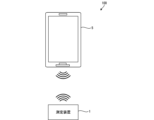
- FIG. 1 is a diagram showing an information management system 100 including an information terminal 5 of the present invention and a measuring device 1 that performs wireless communication with the information terminal 5.
- FIG. 1 is a diagram showing a thermometer 1a which is an example of a measuring device 1.
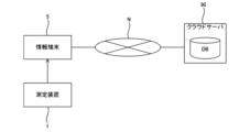
- FIG. 2 is a diagram showing an example in which an information terminal 5 is connected to a network.
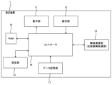
- FIG. 1 is a block diagram showing a configuration of a measuring device 1.
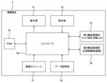
- 2 is a block diagram showing a configuration of an information terminal 5.
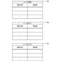
- FIG. 4 is a diagram showing an example of a table stored in the information terminal 5.
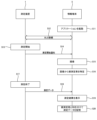
- FIG. 1 is a sequence diagram showing the operation of a measuring device 1 and an information terminal 5 in an information management system 100.
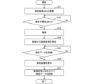
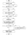
- FIG. 10 is a flowchart showing an example of a process performed when an application of an information terminal 5 is started. 10 is a flowchart showing a modified example of the process performed when an application is started on the information terminal 5.
- FIG. 1 shows an information management system 100 including an information terminal 5 of the present invention and a measuring device 1 that wirelessly communicates with the information terminal 5 .
- the measuring device 1 includes a bioinformation measuring device that measures bioinformation such as weight, body composition, blood pressure, pulse, heart rate, body temperature, blood glucose, or blood oxygen saturation, and an activity measuring device that measures activity such as steps, walking distance, or calories burned.
- the measuring device includes a measurement sensor for measuring the amount of measurement.
- the amount of measurement of the measurement sensor includes bioinformation such as weight, body fat percentage, blood pressure, pulse rate, heart rate, body temperature, blood glucose, or blood oxygen saturation, and activity such as steps, running distance, or calories burned, depending on the measuring device.
- the measuring device 1 is, for example, a non-wearable measuring device such as a weight scale, body composition scale, blood pressure meter, thermometer, or blood glucose meter, or a wearable measuring device such as a pedometer or activity meter.
- a non-wearable measuring device is a measuring device that is not wearable, and is used, for example, while installed on the ground or a stand.
- a wearable measuring device is a measuring device that is carried by being attached to the body of the user (person being measured). The measurement device 1 transmits the measured biological information and activity amount as the user's measurement data to the information terminal 5 via wireless communication.
- the information terminal 5 stores the measurement data received from the measuring device 1 in a data storage unit within the information terminal 5.
- the information terminal 5 is also capable of wireless communication with devices other than the measuring device 1, and stores information acquired from external devices in a data storage unit within the information terminal 5.
- the information terminal 5 is an information processing device that analyzes various information acquired from the measuring device 1 and other external devices.
- the information terminal 5 is, for example, a terminal having a display such as a smartphone, a tablet terminal, a laptop computer, a desktop computer, or a wearable terminal.
- the information terminal 5 may be set to acquire measurement data from a specific measuring device 1.
- the specific measuring device 1 from which measurement data is acquired may be registered in advance in the data storage unit of the information terminal 5.
- FIG. 2 is a diagram showing a thermometer 1a, which is an example of a measuring device 1.
- Thermometer 1a is an example of a bioinformation measuring device that measures the user's body temperature and outputs the measurement result to the user.
- Thermometer 1a also transmits the measurement result as the user's measurement data to information terminal 5 via wireless communication.
- thermometer 1a includes a temperature sensor 21 that senses the user's body temperature, a display 22 that displays the measurement data (body temperature), a communication button 23 for transmitting the measurement data to information terminal 5 via wireless communication, and a power button 24 for starting up thermometer 1a.
- FIG. 3 is a diagram showing an example of an information terminal 5 connected to a network.
- the information terminal 5 may be connected to a cloud server 90 via a wide area network N such as the Internet.
- the information terminal 5 may transmit measurement data stored therein to the cloud server 90 via the wide area network N, and the cloud server 90 may manage the user's measurement data as a database.
- the information terminal 5 may also acquire measurement data managed in the cloud server 90 via the wide area network N, and use the acquired measurement data.
- the measuring device 1 includes a display unit 11 that displays various information, an operation unit 12 operated by the user, a measuring unit 13 that measures biological information and an activity amount, and a wireless communication unit 14 for communicating with an external device.
- the measuring device 1 also includes a RAM 16 that temporarily stores information, a data storage unit 17 that stores information and programs, and a controller 18 that controls the overall operation.
- the display unit 11 is configured, for example, with a liquid crystal display or an organic EL (Electro Luminescence) display.
- the display unit 11 includes, for example, the display unit 22 described in FIG. 2.
- the operation unit 12 is a user interface that accepts user operations such as buttons and a touch panel.
- the buttons include buttons that are physically provided on the measuring device 1 and virtual buttons displayed on the display unit 11.
- the buttons include, for example, the communication button 23 described in FIG. 2.
- the measurement unit 13 measures biological information such as weight, body composition, blood pressure, pulse rate, heart rate, body temperature, blood glucose, blood oxygen saturation, etc., as well as activity levels such as number of steps, walking distance, and calories burned. What is measured varies depending on the subject being measured by the measurement device 1.
- the wireless communication unit 14 is a communication unit that performs short-range wireless communication, for example, a circuit (module) for communicating according to the BLE (Bluetooth Low Energy (registered trademark)) standard.
- the wireless communication unit 14 transmits an advertising signal for wireless communication to an unspecified number of external devices by broadcast communication at a predetermined transmission cycle.
- the wireless communication unit 14 transmits the advertising signal including, for example, the name and attribute information of the measurement device 1.
- the wireless communication (BLE communication) performed by the wireless communication unit 14 is communication that uses, for example, a 2.4 GHz frequency.
- the wireless communication unit 14 transmits measurement data such as biological information and activity levels measured by the measurement unit 13 to the information terminal 5 by BLE communication.
- RAM 16 is composed of semiconductor devices such as DRAM or SRAM, and temporarily stores information and serves as a working area for controller 18.
- the data storage unit 17 is a recording medium that stores parameters, control programs, measurement data, and the like required to realize a specified process.
- the data storage unit 17 is configured, for example, by a hard disk drive (HDD) or a semiconductor storage device (SSD).
- HDD hard disk drive
- SSD semiconductor storage device
- the controller 18 is a processor that realizes a predetermined process by executing a control program.
- health management application software for the measuring device is pre-installed as a control program in the data storage unit 17, and the controller 18 realizes a predetermined process by executing this health management application software.
- the controller 18 controls the wireless communication unit 14 to transmit an advertising signal for wireless communication (BLE communication). Specifically, when the measuring device 1 is started, the controller 18 controls the wireless communication unit 14 to transmit an advertising signal. For example, in the thermometer 1a shown in FIG. 2, when the power button 24 is turned on and then the communication button 23 is pressed, the controller 18 controls the wireless communication unit 14 to transmit an advertising signal.
- the information terminal 5 includes a display unit 51 that displays various information, an operation unit 52 that is operated by the user, and a first wireless communication unit 53 and a second wireless communication unit 54 for communicating with external devices.
- the information terminal 5 also includes a RAM 55 that temporarily stores information, a data storage unit 56 that stores information and programs, an imaging module 57 that can capture images, and a controller 58 that controls the overall operation.
- the controller 58 is an example of the "control unit" of the present invention.
- the display unit 51 is configured, for example, with a liquid crystal display or an organic EL display.
- the operation unit 52 is a user interface that accepts user operations such as buttons and a touch panel.
- the buttons include buttons that are physically provided on the information terminal 5 and virtual buttons displayed on the display unit 51.
- the first wireless communication unit 53 is a communication unit that performs cellular communication, for example, a circuit (module) for communicating according to standards such as 4G, 5G, and LTE (Long Term Evolution: registered trademark).
- the first wireless communication unit 53 is also a communication unit that performs wireless LAN communication, for example, a circuit (module) for communicating according to standards such as Wi-Fi (registered trademark).
- the second wireless communication unit 54 is a communication unit that performs short-range wireless communication, for example, a circuit (module) for communicating according to the BLE standard.
- the second wireless communication unit 54 performs BLE communication with the wireless communication unit 14 of the measuring device 1 to acquire measurement data of the user measured by the measuring device 1.
- the second wireless communication unit 54 receives the advertising signal transmitted from the wireless communication unit 14 of the measuring device 1 by scanning.
- the second wireless communication unit 54 recognizes the measuring device 1 from the received advertising signal, and transmits a connection request to the measuring device 1 when a communication connection is desired.
- the measuring device 1 waits for a connection request for a predetermined time, and when a connection request is received within the predetermined time, it stops transmitting the advertising signal and switches to one-to-one connection communication with the other party of the connection request.
- RAM 55 is composed of semiconductor devices such as DRAM or SRAM, and temporarily stores information and serves as a working area for controller 58.
- the data storage unit 56 is a recording medium that stores parameters necessary to realize a specified process, a control program, and measurement data acquired from the measuring device 1.
- the data storage unit 56 is configured, for example, by a hard disk drive (HDD) or a semiconductor storage device (SSD).
- the controller 58 is a processor that performs predetermined processing by executing a control program.
- health management application software for information terminals is pre-installed as a control program in the data storage unit 56, and the controller 58 performs predetermined processing by executing this health management application software.
- the controller 58 controls the second wireless communication unit 54 to receive an advertising signal by scanning.
- the controller 58 controls the second wireless communication unit 54 to transmit a connection request to the measuring device 1.
- the connection request is received by the measuring device 1, the communication of the measuring device 1 is switched to one-to-one connection communication with the information terminal 5, and the information terminal 5 and the measuring device 1 are in a BLE connected state.
- the controller 58 also identifies the person being measured based on the image captured by the imaging module 57 when the measuring device 1 is measuring the biometric information, the amount of activity, and the like.
- the measurement time means, for example, during the measurement of the biometric information, and may include the start of the measurement and immediately after the measurement without being limited to during the measurement. Identifying the person being measured means identifying a user who matches the person being measured from at least one user who is registered in advance by the user in the information terminal 5 in which the health management application software is installed, and identifying the user ID (Identification) set for the identified user.
- the controller 58 can identify the person being measured from multiple users registered in the information terminal 5 based on the image captured.
- the controller 58 identifies the person being measured by authenticating the user's face.
- the controller 58 associates the person being measured identified based on the captured image with the measurement data received from the measuring device 1 and stores them in the data storage unit 56.
- the controller 58 controls the display of a content image on the display unit 51 while the measuring device 1 is measuring biological information, etc.
- the content image may be, for example, an image related to the measurement, such as a provisional measurement result during the measurement, the remaining time of the measurement, or a guidance message such as "The data is being measured. Please wait a moment.” If the measuring device 1 is a thermometer 1a that is held under the arm, it may be a determination result of whether the thermometer 1a is properly held under the arm, or a message guiding the subject to hold the thermometer 1a properly under the arm if the thermometer 1a is not properly held under the arm, or an image that is unrelated to the measurement but attracts the subject's interest (for example, an animation or game for children).
- the measuring device 1 is a thermometer 1a that is held under the arm
- the information terminal 5 is held in the hand that holds the thermometer 1a during the measurement
- the controller 58 may display a warning image as the content image if the information terminal 5 moves more than a certain amount, or a fun image if the information terminal 5 does not move more than a certain amount (if it is still). Displaying such content images can increase the subject's motivation to look at the information terminal 5 during measurement, increase the subject's motivation to perform the measurement by linking the measuring device 1 and the information terminal 5, and assist in appropriate measurement.
- the controller 58 causes the imaging module 57 to capture an image when the measuring device 1 is measuring biometric information, etc., without any imaging operation from the user.
- An imaging operation is an explicit instruction operation to capture an image, such as pressing an imaging button.
- "During measurement" means, for example, when a trigger occurs such as the health management application software being launched on the information terminal 5, the BLE connection with the measuring device 1 being completed, the measurement start button displayed on the information terminal 5 being pressed to start measurement by the measuring device 1, measurement of biometric information, etc., starting in the measuring device 1, displaying a content image during measurement on the display unit 51, displaying the measurement results on the display unit 51, etc.
- the imaging module 57 is an imaging unit that is provided so as to be able to capture an image of an observer observing the display unit 51.
- an image of the observer observing the display unit 51 is captured by an in-camera that is mounted on the liquid crystal panel side and captures an image in the forward direction.
- Fig. 6 is a diagram showing an example of a measurement data table stored in the data storage unit 56 of the information terminal 5.
- the measurement data tables 56a, 56b, and 56c store, for example, the measurement date and time of the measurement data and the measurement value in association with each other.
- the measurement value is body temperature [°C].
- the information terminal 5 is configured to be able to store the measurement data of multiple users in the data storage unit 56.
- the measurement data of users A, B, and C is stored in the data storage unit 56.
- the data storage unit 56 stores measurement data tables 56a, 56b, and 56c for storing the measurement data of users A, B, and C.
- Measurement data table 56a stores the measurement data of user A.
- Measurement data table 56b stores the measurement data of user B.
- Measurement data table 56c stores the measurement data of user C.
- User A is the owner of information terminal 5.
- Users B and C are user A's children.
- measurement data tables 56a, 56b, and 56c are stored in user A's information terminal 5, which store the measurement data of user A (parent), user B (child 1), and user C (child 2).
- images of user A, user B, and user C for face recognition are preregistered in the data storage unit 56.
- the images of user A, user B, and user C are registered in association with measurement data tables 56a, 56b, and 56c.
- the controller 58 of the information terminal 5 identifies user A, user B, or user C by face recognition based on the image captured by the imaging module 57.
- the controller 58 refers to the measurement data table associated with the identified user.
- Fig. 7 is a sequence diagram showing the operation of the measurement device 1 and the information terminal 5 in the information management system 100.
- the information terminal 5 launches the health management application (step S11).
- the health management application of the information terminal 5 is launched, a connection request signal is sent from the information terminal 5 to the measurement device 1, and the communication of the measurement device 1 is switched to one-to-one connection communication with the information terminal 5, thereby establishing a BLE connection between the information terminal 5 and the measurement device 1 (step S12).
- the measuring device 1 starts measuring the measurement data (step S13).
- the measurement of the measurement data is started, for example, by the user operating the measuring device 1 to start measurement. Specifically, if the measuring device 1 is a thermometer 1a, the user holds the thermometer 1a under his arm.
- the measuring device 1 transmits a measurement start notification signal to the information terminal 5 to notify that the measurement of the measurement data has started (step S14).
- the information terminal 5 that has received the notification to start measurement captures an image of the user with the imaging module 57 of the information terminal 5 (step S15).
- the information terminal 5 is a smartphone
- the image of the user is captured with the in-camera.
- the user touches an icon on the display unit 51 of the information terminal 5 to launch a health management application.
- the information terminal 5 is a smartphone
- the user is looking at the smartphone screen while the measurement data is being measured after the health management application has been launched. Therefore, it is possible to capture an image of the user's face with the in-camera of the smartphone.
- an image such as "Measuring data. Please wait a moment" may be displayed on the smartphone screen.
- the health management application may be launched and then the child may hold the parent's smartphone to measure the measurement data. This makes it possible to capture an image of the child's face using the smartphone's front camera.
- the measured data of the child may also be stored in, for example, measurement data tables 56b and 56c (see Figure 6) of the parent's smartphone. In this case, to keep the child looking at the smartphone screen, for example, an animation for children may be displayed on the smartphone screen.
- the information terminal 5 identifies the person being measured from the captured image of the user (step S16).
- the information terminal 5 for example, refers to the facial image of the user registered in the information terminal 5 and determines whether the captured user is a registered user through facial authentication.
- step S17 when the measurement started in step S13 is completed (step S17), the measuring device 1 transmits the measured data to the information terminal 5 (step S18).
- the information terminal 5 displays the measurement result on the display unit 51 based on the measurement data received from the measuring device 1 (step S19).
- the information terminal 5 displays the measurement result on the display unit 51, regarding the measurement data received from the measuring device 1 as the measurement data of the user identified in step S16.
- step S16 it may be possible to check whether the person being measured identified from the image (step S16) is correct. For example, if the person being measured identified from the image is user B (child 1) as described in FIG. 6, a confirmation pop-up such as "The person just measured is child 1, right?" may be displayed on the display unit 51. If the user responds with "No (that's not right),” a list of other registered users (e.g. user A (parent), user C (child 2)) may be displayed on the display unit 51 to allow the user to select the correct person being measured.
- a confirmation pop-up such as "The person just measured is child 1, right?"
- a list of other registered users e.g. user A (parent), user C (child 2)
- the information terminal 5 stores the measurement data in the measurement data table of the data storage unit 56 in association with the person being measured (step S20).
- the information terminal 5 may transmit the user and the measurement data stored in the measurement data table to the cloud server 90.
- the measurement of the measurement data in the measuring device 1 is started based on the user's operation to start measurement on the measuring device 1, but this is not limited to this.
- the measurement may be started when a "measurement start button" displayed on the display unit 51 in the health management application of the information terminal 5 is touched and an instruction to start measurement is sent from the information terminal 5 to the measuring device 1.
- the notification of the start of measurement from the measuring device 1 to the information terminal 5 in step S14 above may be omitted.
- Fig. 8 is a flowchart showing an example of the operation when an application is started on the information terminal 5. This processing of the operation is started when the health management application on the information terminal 5 is started.
- the information terminal 5 establishes a BLE connection with the measuring device 1 (step S31).
- the information terminal 5 receives an advertising signal from the measuring device 1, it transmits a connection request to the measuring device 1.
- the measuring device 1 receives the connection request, the communication of the measuring device 1 is switched to one-to-one connection communication with the information terminal 5, and the information terminal 5 and the measuring device 1 are BLE connected.
- the information terminal 5 determines whether or not data measurement has started in the measuring device 1 (step S32). For example, if the information terminal 5 has sent an instruction to start data measurement to the measuring device 1, the information terminal 5 can determine by itself whether or not data measurement has started. If the information terminal 5 has not sent an instruction to start data measurement to the measuring device 1, the information terminal 5 makes this determination by receiving a notification of the start of measurement from the measuring device 1.
- step S32: No If measurement by the measuring device 1 has not started in step S32 (step S32: No), the information terminal 5 repeats the process of step S32. If measurement by the measuring device 1 has started in step S32 (step S32: Yes), the information terminal 5 captures an image of the user with the imaging module 57 (step S33). For example, if the information terminal 5 is a smartphone, capturing an image of the user using the front camera is the same as the process described in step S15 of FIG. 7 above.
- the information terminal 5 identifies the person being measured from the image of the user acquired in the image capture in step S33 (step S34).
- the person being measured is identified by referencing the facial images of the users registered in the data storage unit 56 and performing facial authentication to determine whether the captured user matches a registered user.
- the information terminal 5 determines whether or not the measurement data of the subject measured by the measuring device 1 has been received from the measuring device 1 (step S35).
- step S35: No If no measurement data has been received in step S35 (step S35: No), the information terminal 5 repeats the process of step S35. If measurement data has been received in step S35 (step S35: Yes), the information terminal 5 displays the measurement results of the measuring device 1 on the display unit 51 based on the received measurement data (step S36). The information terminal 5 displays the received measurement data on the display unit 51 as the measurement data of the user identified in step S34. For example, the information terminal 5 displays the measurement data with the user's face image, name, etc. attached.
- the information terminal 5 associates the measurement data received from the measurement device 1 with the person being measured, and stores the data in the measurement data table of the data storage unit 56 (step S37).
- This person being measured is the user identified in step S34 as matching the person being measured.
- the information terminal 5 when the information terminal 5 is connected to the measuring device 1 via BLE by starting the health management application, the information terminal 5 identifies the subject from among the multiple users registered in the information terminal 5 based on the image obtained by capturing an image of the observer on the display unit 51 when the measuring device 1 is measuring data. The information terminal 5 then stores the identified subject and the measurement data received from the measuring device 1 in association with each other in the data storage unit 56. With this configuration, when the measuring device 1 is measuring data, it is possible to capture an image of the person performing the measurement by capturing an image of the observer on the display unit 51 of the information terminal 5 that is in BLE communication with the measuring device 1.
- the subject is identified from among pre-registered user images based on the image of the observer on the display unit 51, the subject can be identified accurately. This allows the measurement data received from the measuring device 1 to be easily and reliably associated with the correct subject. Furthermore, even when multiple users of the measuring device 1 each have different information terminals 5, it is possible to prevent the measurement data received from the measuring device 1 from being transmitted to and stored in the information terminal 5 of a user other than the subject.
- the information terminal 5 displays a content image on the display unit 51 of the information terminal 5 while the measuring device 1 is measuring biometric information, etc.
- This configuration makes it possible to direct the subject's gaze toward the display unit 51 of the information terminal 5 on which the content image is displayed while the biometric information, etc. is being measured.
- This allows the imaging module 57 of the information terminal 5 to accurately capture an image of the subject. Therefore, the measurement data can be easily and reliably associated with the correct subject.
- the information terminal 5 can capture an image of the person being measured, whose data is being measured, using the imaging module 57 (e.g., an in-camera) when the measuring device 1 is measuring biological information, without the user having to perform an imaging operation.
- the imaging module 57 e.g., an in-camera
- Fig. 9 is a flow chart showing a modified example of the operation when an application is started on the information terminal 5. This operation starts when the health management application on the information terminal 5 is started, similar to the process in Fig. 8.
- step S31 to step S36 are the same as the processes from step S31 to step S36 in the operation process shown in FIG. 8. Therefore, a description of the processes in these steps will be omitted.
- the information terminal 5 inquires of the user as to whether the person being measured identified in step S34 is correct, i.e., whether the user's face image, name, etc. displayed on the display unit 51 in step S36 matches the person being measured, and accepts the response from the user (step S337a).
- the information terminal 5 determines whether or not a response indicating that the inquiry in step S37a is correct has been received from the user (step S37b). If a response indicating that the inquiry is correct has been received from the user (step S37b: Yes), the information terminal 5 associates the measurement data received from the measuring device 1 with the subject and stores the measurement data in the measurement data table of the data storage unit 56 (step S37c).
- step S37b if in step S37b an answer indicating the correctness is not received from the user (step S37b: No), the information terminal 5 receives the selection of the correct person to be measured from the user (step S37d).
- the information terminal 5 may display facial images of registered users on the display unit 51 and receive a selection from among them. If the person to be measured is not registered, the information terminal 5 may receive a registration operation to newly register the user. Then, after receiving the selection of the correct person to be measured from the user, the information terminal 5 stores the measurement data in the measurement data table in association with the person to be measured (step S37c).
- the information terminal 5 of the modified example is configured to inquire of the user as to whether the person being measured identified by the information terminal 5 based on the captured image is the correct person being measured, and if not, to allow the user to set it correctly. This allows for even more accurate and reliable correspondence between the measurement data and the person being measured.
- the information terminal 5 performs short-range wireless communication with the measuring device 1, but this is not limiting.
- the information terminal 5 may be connected to the measuring device 1 via a communication line and perform wired communication with the measuring device 1.
- an image of the user may be captured by the out-camera of the smartphone.
- the owner of the smartphone is user A (parent)
- the subject of the biological information measurement is user A's child 1 (user B) or child 2 (user C)
- the parent may capture an image of the child by the out-camera.
- the control method of the information terminal 5 described in the above embodiment can be realized by executing a prepared control program on a computer.
- the control program is recorded in a computer-readable storage medium and executed by reading it from the storage medium.
- the control program may be provided in a form stored in a non-transient storage medium such as a flash memory, or may be provided via a network such as the Internet.
- the computer that executes the control program may be included in the information terminal 5, or may be included in an electronic device such as a smartphone, tablet terminal, or personal computer that can communicate with the information terminal 5, or may be included in a server device that can communicate with the information terminal 5 and the electronic device.
- Measurement device 1a Thermometer 5 Information terminal 11, 22, 51 Display unit 12, 52 Operation unit 13 Measurement unit 14 Wireless communication unit 16, 55 RAM 17, 56 Data storage unit 18, 58 Controller 21 Temperature sensor 23 Communication button 24 Power button 53 First wireless communication unit 54 Second wireless communication units 56a to 56c Measurement data table 57 Imaging module 90 Cloud server 100 Information management system
Landscapes
- Life Sciences & Earth Sciences (AREA)
- Health & Medical Sciences (AREA)
- Medical Informatics (AREA)
- Biophysics (AREA)
- Pathology (AREA)
- Engineering & Computer Science (AREA)
- Biomedical Technology (AREA)
- Heart & Thoracic Surgery (AREA)
- Physics & Mathematics (AREA)
- Molecular Biology (AREA)
- Surgery (AREA)
- Animal Behavior & Ethology (AREA)
- General Health & Medical Sciences (AREA)
- Public Health (AREA)
- Veterinary Medicine (AREA)
- Measuring And Recording Apparatus For Diagnosis (AREA)
- Measurement Of The Respiration, Hearing Ability, Form, And Blood Characteristics Of Living Organisms (AREA)
Abstract
被測定者の測定データを簡単かつ正確に対応付けて管理することが可能な情報端末、制御方法、及び制御プログラムを提供する。 本発明の一側面に係る情報端末(5)は、第2無線通信部(54)と、データ記憶部(56)と、撮像モジュール(57)と、コントローラ(58)と、を備える。第2無線通信部(54)は生体情報の測定装置(1)と通信可能である。データ記憶部(56)は測定装置(1)により得られた測定データを記憶可能である。撮像モジュール(57)は撮像可能である。コントローラ(58)は、測定装置(1)による測定時に撮像により得られた画像に基づいて被測定者を特定し、被測定者と測定装置(1)から受信した測定データと、を対応付けてデータ記憶部(56)に記憶させる。
Description
本発明は、情報端末、制御方法、及び制御プログラムに関する。
従来、被測定者に関するデータを測定装置で測定し、測定したデータを被測定者に対応付けて記憶する装置が知られている。例えば、特許文献1には、測定装置に備えられたカメラで被測定者を撮影し、撮影した画像に基づいて被測定者を特定し、特定した被測定者とその被測定者の測定データとを対応付けた被測定者情報を通信端末に送信し、通信端末に被測定者情報を記憶する生体情報処理装置が記載されている。
また、特許文献2には、撮影装置と測定装置から構成される測定ユニットと、ユーザ端末と、を有し、測定装置によってユーザの身体データを測定し、撮影装置によってユーザ画像を撮影し、ユーザ端末によりユーザの身体データ及びユーザ画像を撮像装置から受信する管理システムが記載されている。
また、特許文献3には、生体測定機器に関する情報を取得する機器情報取得部と、機器情報取得部が取得した生体測定機器に関する情報に基づいてユーザを特定するユーザ特定部と、機器情報取得部が取得した情報をユーザ特定部が特定したユーザに対応付けるデータ処理部と、を備える情報処理装置が記載されている。
また、特許文献4には、把持手段が所定の対象により把持された場合に、所定の対象の身体機能に関する身体情報を取得部が取得し、所定の対象の画像を撮像部が取得し、取得した画像に基づいて所定の対象を識別部が認識し、所定の対象と身体情報とを紐付けて記憶するロボットが記載されている。
このように被測定者の測定データをその被測定者に対応付けて管理することに関しては特許文献1から特許文献4に示すように各種提案されている。しかし、その対応付けの仕方についてはユーザにとってさらに利便性の向上が望まれる。
本発明は、一側面では、このような実情を鑑みてなされたものであり、その目的は、測定データと被測定者とを簡単且つ正確に対応付けることが可能な情報端末、制御方法、及び制御プログラムを提供することである。
本発明は、上記の課題を解決するために、以下の構成を採用する。
(1)
生体情報の測定装置と通信可能な通信部と、
前記測定装置により得られた測定データを記憶可能な記憶部と、
撮像が可能な撮像部と、
前記測定装置による測定時に前記撮像により得られた画像に基づいて被測定者を特定し、前記被測定者と、前記測定装置から受信した前記測定データと、を対応付けて前記記憶部に記憶させる制御部と、
を備える情報端末。
生体情報の測定装置と通信可能な通信部と、
前記測定装置により得られた測定データを記憶可能な記憶部と、
撮像が可能な撮像部と、
前記測定装置による測定時に前記撮像により得られた画像に基づいて被測定者を特定し、前記被測定者と、前記測定装置から受信した前記測定データと、を対応付けて前記記憶部に記憶させる制御部と、
を備える情報端末。
(1)によれば、測定装置の測定時において撮像された画像に基づき被測定者が特定されるので、測定装置から受信した測定データを簡単且つ確実に正しい被測定者と対応付けることができる。
(2)
(1)に記載の情報端末であって、
前記通信部は、前記測定装置と近距離無線通信を行う、
情報端末。
(1)に記載の情報端末であって、
前記通信部は、前記測定装置と近距離無線通信を行う、
情報端末。
(2)のように、測定装置から生体情報の測定データを受信するには近距離無線通信が適している。
(3)
(1)又は(2)に記載の情報端末であって、
前記制御部は、前記画像に基づいて、前記情報端末に登録された複数のユーザの中から前記被測定者を特定する、
情報端末。
(1)又は(2)に記載の情報端末であって、
前記制御部は、前記画像に基づいて、前記情報端末に登録された複数のユーザの中から前記被測定者を特定する、
情報端末。
(3)によれば、撮像画像に基づいて、予め登録されたユーザの中から被測定者が特定されるので、測定データと被測定者との対応付けの操作をユーザが行う必要がなく、簡単且つ確実に対応付けできる。
(4)
(1)から(3)のいずれかに記載の情報端末であって、
前記制御部は、前記測定装置による測定中に前記撮像により得られた画像に基づいて前記被測定者を特定する、
情報端末。
(1)から(3)のいずれかに記載の情報端末であって、
前記制御部は、前記測定装置による測定中に前記撮像により得られた画像に基づいて前記被測定者を特定する、
情報端末。
(4)によれば、測定装置の測定中における撮像画像に基づいて被測定者が特定されるので、測定装置から受信した測定データを簡単且つ確実に正しい被測定者と対応付けることができる。
(5)
(4)に記載の情報端末であって、
前記測定装置による測定中にコンテンツ画像を表示する表示部を備える、
情報端末。
(4)に記載の情報端末であって、
前記測定装置による測定中にコンテンツ画像を表示する表示部を備える、
情報端末。
(5)によれば、コンテンツ画像が表示される表示部に被測定者の視線を向かせることが可能であり、被測定者の画像を適切に撮像することができる。
(6)
(1)から(5)のいずれかに記載の情報端末であって、
前記制御部は、ユーザからの撮像操作なしに、前記測定装置による測定時に前記撮像部に前記撮像を実行させる、
情報端末。
(1)から(5)のいずれかに記載の情報端末であって、
前記制御部は、ユーザからの撮像操作なしに、前記測定装置による測定時に前記撮像部に前記撮像を実行させる、
情報端末。
(6)によれば、測定装置による測定時に被測定者の画像を自動撮像して、被測定者を特定することが可能である。
(7)
(1)から(6)のいずれかに記載の情報端末であって、
画像を表示可能な表示部を備え、
前記撮像部は、前記表示部の観察者を撮像可能に設けられている、
情報端末。
(1)から(6)のいずれかに記載の情報端末であって、
画像を表示可能な表示部を備え、
前記撮像部は、前記表示部の観察者を撮像可能に設けられている、
情報端末。
(7)によれば、表示部に向き合った状態の被測定者の画像を撮像することが可能である。
(8)
生体情報の測定装置と通信可能な通信部と、前記測定装置により得られた測定データを記憶可能な記憶部と、撮像が可能な撮像部と、を備える情報端末の制御方法であって、
前記測定装置による測定時に前記撮像により得られた画像に基づいて被測定者を特定し、
前記被測定者と、前記測定装置から受信した前記測定データと、を対応付けて前記記憶部に記憶させる、
制御方法。
生体情報の測定装置と通信可能な通信部と、前記測定装置により得られた測定データを記憶可能な記憶部と、撮像が可能な撮像部と、を備える情報端末の制御方法であって、
前記測定装置による測定時に前記撮像により得られた画像に基づいて被測定者を特定し、
前記被測定者と、前記測定装置から受信した前記測定データと、を対応付けて前記記憶部に記憶させる、
制御方法。
(8)によれば、測定装置の測定時において撮像された画像に基づき被測定者が特定されるので、測定装置から受信した測定データを簡単且つ確実に正しい被測定者と対応付けることができる。
(9)
生体情報の測定装置と通信可能な通信部と、前記測定装置により得られた測定データを記憶可能な記憶部と、撮像が可能な撮像部と、を備える情報端末の制御プログラムであって、
前記情報端末のプロセッサに、
前記測定装置による測定時に前記撮像により得られた画像に基づいて被測定者を特定し、
前記被測定者と、前記測定装置から受信した前記測定データと、を対応付けて前記記憶部に記憶させる、
処理を実行させるための制御プログラム。
生体情報の測定装置と通信可能な通信部と、前記測定装置により得られた測定データを記憶可能な記憶部と、撮像が可能な撮像部と、を備える情報端末の制御プログラムであって、
前記情報端末のプロセッサに、
前記測定装置による測定時に前記撮像により得られた画像に基づいて被測定者を特定し、
前記被測定者と、前記測定装置から受信した前記測定データと、を対応付けて前記記憶部に記憶させる、
処理を実行させるための制御プログラム。
(9)によれば、測定装置の測定時において撮像された画像に基づき被測定者が特定されるので、測定装置から受信した測定データを簡単且つ確実に正しい被測定者と対応付けることができる。
本発明によれば、測定データと被測定者とを簡単且つ正確に対応付けることが可能な情報端末、制御方法、及び制御プログラムを提供することができる。
以下、本発明の一側面に係る実施の形態を、図面に基づいて説明する。
§1 適用例
<本発明を適用した情報管理システム100>
図1は、本発明の情報端末5と、当該情報端末5と無線通信を行う測定装置1と、を含む情報管理システム100である。
<本発明を適用した情報管理システム100>
図1は、本発明の情報端末5と、当該情報端末5と無線通信を行う測定装置1と、を含む情報管理システム100である。
測定装置1は、体重、体組成、血圧、脈拍、心拍、体温、血糖、又は血中酸素飽和度等の生体情報を測定する生体情報測定装置と、歩数、歩行距離、又は消費カロリー等の活動量を測定する活動量測定装置と、を含む。測定装置には、測定対象量を測定するための測定用センサが含まれる。測定用センサの測定対象量には、測定装置に応じて、体重、体脂肪率、血圧値、脈拍数、心拍数、体温、血糖値、又は血中酸素飽和度等の生体情報や、歩数、走行距離、又は消費カロリー等の活動量が含まれる。測定装置1は、例えば、体重計、体組成計、血圧計、体温計、血糖計等の非ウェアラブルな測定装置、又は歩数計、活動量計等のウェアラブルな測定装置である。非ウェアラブルな測定装置とは、ウェアラブルでない測定装置であり、例えば、地面や台の上に設置された状態で使用される測定装置である。ウェアラブルな測定装置とは、ユーザ(被測定者)の身体への装着により携帯される測定装置である。測定装置1は、測定した生体情報及び活動量をユーザの測定データとして、無線通信により情報端末5に送信する。
情報端末5は、測定装置1から受信した測定データを情報端末5内のデータ記憶部に記憶する。また、情報端末5は、測定装置1以外の機器とも無線通信を行うことが可能であり、外部機器から取得した情報を情報端末5内のデータ記憶部に記憶する。情報端末5は、測定装置1及びその他の外部機器から取得した種々の情報を分析する情報処理装置である。情報端末5は、例えば、スマートフォン、タブレット端末、ノートパソコン、及びデスクトップパソコン、ウェアラブル端末等のディスプレイを有する端末である。情報端末5は、特定の測定装置1から測定データを取得するように設定されていてもよい。測定データを取得する特定の測定装置1は、情報端末5のデータ記憶部に予め登録されていてもよい。
図2は、測定装置1の一例である体温計1aを示す図である。体温計1aは、生体情報測定装置の一例であり、ユーザの体温を測定し、その測定結果をユーザに出力する。また、体温計1aは、測定結果をユーザの測定データとして無線通信により情報端末5に送信する。例えば、体温計1aは、ユーザの体温を感知する感温部21と、測定データ(体温)を表示する表示部22と、測定データを無線通信により情報端末5へ送信させるための通信ボタン23と、体温計1aを起動させるための電源ボタン24と、を備える。
図3は、情報端末5がネットワーク接続される一例を示す図である。図3に示すように、情報端末5は、インターネット等の広域ネットワークNを介してクラウドサーバ90に接続されてもよい。情報端末5は、自己が記憶する測定データを、広域ネットワークNを介してクラウドサーバ90に送信し、クラウドサーバ90においてデータベースとしてユーザの測定データを管理するようにしてもよい。また、情報端末5は、クラウドサーバ90において管理される測定データを、広域ネットワークNを介して取得し、取得した測定データを利用するようにしてもよい。
§2 構成例
<測定装置1の構成>
図4は、測定装置1の構成を示すブロック図である。測定装置1は、種々の情報を表示する表示部11と、ユーザが操作を行う操作部12と、生体情報及び活動量等を測定する測定部13と、外部機器と通信を行うための無線通信部14と、を備える。また、測定装置1は、情報を一時的に記憶するRAM16と、情報やプログラムを記憶するデータ記憶部17と、全体の動作を制御するコントローラ18と、を備える。
<測定装置1の構成>
図4は、測定装置1の構成を示すブロック図である。測定装置1は、種々の情報を表示する表示部11と、ユーザが操作を行う操作部12と、生体情報及び活動量等を測定する測定部13と、外部機器と通信を行うための無線通信部14と、を備える。また、測定装置1は、情報を一時的に記憶するRAM16と、情報やプログラムを記憶するデータ記憶部17と、全体の動作を制御するコントローラ18と、を備える。
表示部11は、例えば、液晶ディスプレイや有機EL(Electro Luminescence)ディスプレイで構成される。表示部11には、例えば図2で説明した表示部22が含まれる。操作部12は、ボタンやタッチパネルのようなユーザ操作を受け付けるユーザインタフェースである。ボタンは、測定装置1に物理的に設けられたボタンや表示部11に表示された仮想的なボタンを含む。ボタンには、例えば図2で説明した通信ボタン23が含まれる。
測定部13は、体重、体組成、血圧、脈拍、心拍、体温、血糖、血中酸素飽和度等の生体情報や、歩数、歩行距離、消費カロリー等の活動量を測定する。何を測定するかは、測定装置1の測定対象により異なる。
無線通信部14は、近距離無線通信を行う通信部、例えば、BLE(Bluetooth Low Energy(登録商標))規格にしたがい通信を行うための回路(モジュール)である。無線通信部14は、無線通信を行うためのアドバタイズ信号をブロードキャスト通信により不特定多数の外部機器に所定の発信周期で送信する。無線通信部14は、アドバタイズ信号に、例えば、測定装置1の名前や属性情報を含めて送信する。無線通信部14が行う無線通信(BLE通信)は、例えば2.4GHz周波数を利用する通信である。無線通信部14は、測定部13で測定された生体情報及び活動量等の測定データを、BLE通信により情報端末5に送信する。
RAM16は、例えば、DRAMやSRAM等の半導体デバイスで構成され、情報を一時的に記憶するとともに、コントローラ18の作業エリアとなる。
データ記憶部17は、所定の処理を実現するために必要なパラメータ、制御プログラム、及び測定データ等を記憶する記録媒体である。データ記憶部17は、例えば、ハードディスクドライブ(HDD)や半導体記憶装置(SSD)で構成される。
コントローラ18は、制御プログラムを実行することで所定の処理を実現するプロセッサである。なお、本実施形態では、データ記憶部17に制御プログラムとして、例えば、測定装置用の健康管理アプリケーションソフトが予めインストールされており、コントローラ18はこの健康管理アプリケーションソフトを実行することにより所定の処理を実現する。
例えば、コントローラ18は、無線通信部14に対して、無線通信(BLE通信)のためのアドバタイズ信号を送信させるように制御する。具体的には、コントローラ18は、測定装置1が起動されると、無線通信部14に対して、アドバタイズ信号を送信させるように制御する。例えば図2に示す体温計1aにおいて電源ボタン24がオンされた後、通信ボタン23が押されると、コントローラ18はアドバタイズ信号を送信するように無線通信部14を制御する。
<情報端末5の構成>
図5は、情報端末5の構成を示すブロック図である。情報端末5は、種々の情報を表示する表示部51と、ユーザが操作を行う操作部52と、外部機器と通信を行うための第1無線通信部53及び第2無線通信部54と、を備える。また、情報端末5は、情報を一時的に記憶するRAM55と、情報やプログラムを記憶するデータ記憶部56と、撮像が可能な撮像モジュール57と、全体の動作を制御するコントローラ58と、を備える。コントローラ58は、本発明の「制御部」の一例である。
図5は、情報端末5の構成を示すブロック図である。情報端末5は、種々の情報を表示する表示部51と、ユーザが操作を行う操作部52と、外部機器と通信を行うための第1無線通信部53及び第2無線通信部54と、を備える。また、情報端末5は、情報を一時的に記憶するRAM55と、情報やプログラムを記憶するデータ記憶部56と、撮像が可能な撮像モジュール57と、全体の動作を制御するコントローラ58と、を備える。コントローラ58は、本発明の「制御部」の一例である。
表示部51は、例えば、液晶ディスプレイや有機ELディスプレイで構成される。操作部52は、ボタンやタッチパネルのようなユーザ操作を受け付けるユーザインタフェースである。ボタンは、情報端末5に物理的に設けられたボタンや表示部51に表示された仮想的なボタンを含む。
第1無線通信部53は、セルラ通信を行う通信部、例えば、4G、5G、LTE(Long Term Evolution:登録商標)等の規格にしたがい通信を行うための回路(モジュール)である。また、第1無線通信部53は、無線LAN通信を行う通信部、例えば、Wi-Fi(登録商標)等の規格にしたがい通信を行うための回路(モジュール)である。第2無線通信部54は、近距離無線通信を行う通信部、例えば、BLE規格にしたがい通信を行うための回路(モジュール)である。
第2無線通信部54は、例えば、測定装置1の無線通信部14とBLE通信を行うことにより、測定装置1で測定されたユーザの測定データを取得する。第2無線通信部54は、スキャンすることで、測定装置1の無線通信部14から送信されているアドバタイズ信号を受信する。第2無線通信部54は、受信したアドバタイズ信号から測定装置1を認識し、通信接続したい場合に接続要求を測定装置1に対して送信する。なお、測定装置1は、アドバタイズ信号を発信した後に、所定時間、接続要求を待ち、所定時間内に接続要求を受信するとアドバタイズ信号の発信を停止し、接続要求相手との1対1の接続通信に切り替える。
RAM55は、例えば、DRAMやSRAM等の半導体デバイスで構成され、情報を一時的に記憶するとともに、コントローラ58の作業エリアとなる。
データ記憶部56は、所定の処理を実現するために必要なパラメータ、制御プログラム、及び測定装置1から取得した測定データ等を記憶する記録媒体である。データ記憶部56は、例えば、ハードディスクドライブ(HDD)や半導体記憶装置(SSD)で構成される。
コントローラ58は、制御プログラムを実行することで所定の処理を実現するプロセッサである。なお、本実施形態では、データ記憶部56に制御プログラムとして、例えば、情報端末用の健康管理アプリケーションソフトが予めインストールされており、コントローラ58はこの健康管理アプリケーションソフトを実行することにより所定の処理を実現する。
例えば、コントローラ58は、情報端末用の健康管理アプリケーションソフトが立ち上げられると、スキャンすることでアドバタイズ信号を受信するように第2無線通信部54を制御する。コントローラ58は、測定装置1からのアドバタイズ信号が受信されると、測定装置1へ接続要求を送信するように第2無線通信部54を制御する。接続要求が測定装置1により受信されると、測定装置1の通信が情報端末5との間の1対1の接続通信に切り替えられ、情報端末5と測定装置1とがBLE接続された状態となる。
また、コントローラ58は、測定装置1による生体情報及び活動量等の測定時に撮像モジュール57の撮像により得られた画像に基づいて、被測定者を特定する。測定時とは、例えば生体情報等の測定中のことであるが、測定中に限定されずにその測定の開始時や測定直後を含めてもよい。被測定者を特定するとは、健康管理アプリケーションソフトをインストールした情報端末5に予めユーザにより登録されている少なくとも一人以上のユーザの中から被測定者と一致するユーザを特定することであり、その特定したユーザに設定されているユーザID(Identification)を特定することである。コントローラ58は、撮像により得られた画像に基づいて、情報端末5に登録されている複数のユーザの中から被測定者を特定することが可能である。コントローラ58は、ユーザの顔認証により被測定者を特定する。コントローラ58は、撮像画像に基づき特定した被測定者と、測定装置1から受信した測定データと、を対応付けてデータ記憶部56に記憶させる。
コントローラ58は、測定装置1による生体情報等の測定中に、表示部51にコンテンツ画像を表示させる制御を行う。コンテンツ画像は、例えば、測定中における暫定的な測定結果や、測定の残り時間や、「データを測定しています。そのまま少しお待ちください。」のような案内メッセージ等の測定に関する画像であってもよいし、測定装置1が脇に挟むタイプの体温計1aである場合は体温計1aが適切に脇に挟まれているか否かの判定結果や、体温計1aが適切に脇に挟まれていない場合に体温計1aを適切に脇に挟むことを案内するメッセージでもよいし、測定には関係ないが被測定者の興味を引く画像(例えば子供向けのアニメーションやゲーム)であってもよい。また、測定装置1が脇に挟むタイプの体温計1aである場合、測定中に体温計1aを挟んでいる方の手で情報端末5を持つようにし、コントローラ58は、情報端末5が一定量以上動いた場合には警告画像を、情報端末5が一定量以上動いていない場合(じっとしている場合)には楽しい画像を、コンテンツ画像として表示させてもよい。このようなコンテンツ画像を表示することにより、被測定者が測定中に情報端末5を見るモチベーションを高めたり、測定装置1と情報端末5を連携させて測定を行うモチベーションを高めたり、適切な測定を支援したりすることができる。
コントローラ58は、ユーザからの撮像操作なしに、測定装置1による生体情報等の測定時に撮像モジュール57による撮像を実行させる。撮像操作とは、撮像の明示的な指示操作のこと、例えば撮像ボタンの押下等のことである。「測定時に」とは、例えば、情報端末5で健康管理アプリケーションソフトを起動したこと、測定装置1とのBLE接続が完了したこと、測定装置1による測定を開始させるために情報端末5に表示される測定開始ボタンが押されたこと、測定装置1における生体情報等の測定が始まったこと、測定中のコンテンツ画像を表示部51に表示したこと、測定結果を表示部51に表示したこと、などを契機としてということである。
撮像モジュール57は、表示部51を観察する観察者を撮像可能に設けられている撮像部である。表示部51を観察する観察者の撮像は、例えば情報端末5がスマートフォンである場合、液晶パネル側に搭載されていて手前方向を撮像するインカメラによる撮像である。
<情報端末5の記憶データ>
図6は、情報端末5のデータ記憶部56に記憶されている測定データテーブルの一例を示す図である。図6に示すように、測定データテーブル56a,56b,56cには、例えば測定データの測定日時と、測定値と、が対応付けて記憶されている。例えば測定装置1が体温計1aである場合、測定値は体温[℃]である。
図6は、情報端末5のデータ記憶部56に記憶されている測定データテーブルの一例を示す図である。図6に示すように、測定データテーブル56a,56b,56cには、例えば測定データの測定日時と、測定値と、が対応付けて記憶されている。例えば測定装置1が体温計1aである場合、測定値は体温[℃]である。
情報端末5は、データ記憶部56に複数のユーザの測定データを記憶することができるように構成されている。本例の場合、データ記憶部56には、ユーザAとユーザBとユーザCの測定データが記憶されている。データ記憶部56には、ユーザAとユーザBとユーザCの測定データを記憶するための測定データテーブル56aと56bと56cが記憶されている。
測定データテーブル56aにはユーザAの測定データが記憶されている。測定データテーブル56bにはユーザBの測定データが記憶されている。測定データテーブル56cにはユーザCの測定データが記憶されている。ユーザAは情報端末5の所有者である。ユーザBとユーザCは、ユーザAの子供である。本例の場合、ユーザAの情報端末5にユーザA(親)とユーザB(子1)とユーザC(子2)の測定データを記憶する測定データテーブル56aと56bと56cが記憶されている。
また、データ記憶部56には顔認証のためのユーザA、ユーザB、及びユーザCの画像が予め登録されている。ユーザA、ユーザB、及びユーザCの画像は、測定データテーブル56a,56b,56cと対応付けて登録されている。情報端末5のコントローラ58は、撮像モジュール57が撮像する画像に基づいて、顔認証によりユーザA、ユーザB、又はユーザCを特定する。コントローラ58は、特定したユーザに対応付けられている測定データテーブルを参照する。
§3 動作例
<情報管理システム100の動作例>
次に、図7を参照して、情報管理システム100の動作例を説明する。図7は、情報管理システム100における測定装置1と情報端末5の動作を示すシーケンス図である。
<情報管理システム100の動作例>
次に、図7を参照して、情報管理システム100の動作例を説明する。図7は、情報管理システム100における測定装置1と情報端末5の動作を示すシーケンス図である。
まず、測定装置1の電源を起動する。次に、情報端末5の健康管理アプリケーションを立ち上げるために、表示部51に表示されている例えば「健康管理アプリ」のアイコンをタッチ操作する。
健康管理アプリのアイコンがタッチ操作されると、情報端末5が、健康管理アプリケーションを起動する(ステップS11)。情報端末5の健康管理アプリケーションが立ち上げられると、情報端末5から測定装置1へ接続要求信号が送信され、測定装置1の通信が情報端末5との間の1対1の接続通信に切り替えられことで、情報端末5と測定装置1とがBLE接続される(ステップS12)。
次に、測定装置1が、測定データの測定を開始する(ステップS13)。測定データの測定は、例えばユーザによる測定装置1の測定開始操作により開始される。具体的には、測定装置1が体温計1aである場合、ユーザが体温計1aを脇に挟む。次に、測定装置1が、測定データの測定が開始されたことを通知する測定開始通知の信号を情報端末5へ送信する(ステップS14)。
次に、測定開始の通知を受信した情報端末5が、情報端末5の撮像モジュール57でユーザの画像を撮像する(ステップS15)。例えば情報端末5がスマートフォンである場合、インカメラによりユーザの画像を撮像する。上記のようにユーザは健康管理アプリケーションを立ち上げるために情報端末5の表示部51のアイコンをタッチ操作する。このため、情報端末5がスマートフォンである場合、ユーザは健康管理アプリケーションの立ち上げ後の測定データの測定中にスマートフォンの画面を見ている。したがって、スマートフォンのインカメラによりユーザの顔画像を撮像することが可能である。なお、スマートフォンの画面を見ているユーザの状態を継続させるために、例えば「データを測定しています。そのまま少しお待ちください。」等の画像をスマートフォンの画面に表示するようにしてもよい。
また、被測定者が例えば子供であって、親が付き添って測定データを測定するような場合、健康管理アプリケーションを立ち上げた後に、親のスマートフォンを子どもに持たせて測定データを測定するようにしてもよい。これにより、スマートフォンのインカメラによって子供の顔画像を撮像することが可能である。また、測定された子供のデータを親のスマートフォンの例えば測定データテーブル56b、56c(図6参照)に記憶することができる。この場合、スマートフォンの画面を見ている子供の状態を継続させるために、例えば子供向けのアニメーションをスマートフォンの画面に表示するようにしてもよい。
次に、情報端末5が、撮像されたユーザの画像から被測定者を特定する(ステップS16)。情報端末5は、例えば情報端末5に登録されているユーザの顔画像を参照して、撮像されたユーザが登録済みのユーザであるか否かを顔認証により判定する。
次に、測定装置1は、ステップS13で開始した測定が終了すると(ステップS17)、測定されたデータを情報端末5へ送信する(ステップS18)。
次に、情報端末5が、測定装置1から受信した測定データに基づき、その測定結果を表示部51に表示する(ステップS19)。情報端末5は、測定装置1から受信した測定データをステップS16で特定したユーザの測定データであるとして測定結果を表示部51に表示する。
なお、測定結果を表示部51に表示する前に、画像から特定した被測定者(ステップS16)に誤りが無いか否かの確認を行ってもよい。例えば、画像から特定した被測定者が図6で説明したユーザB(子1)であった場合、「直前の被測定者は、子1ですね?」等の確認ポップアップを表示部51に表示してもよい。これに対して「いいえ(違います)」の応答操作があった場合、例えば他の登録ユーザのリスト(例えば、ユーザA(親)、ユーザC(子2))を表示部51に表示して、正しい被測定者を選択してもらうようにしてもよい。
次に、情報端末5が、被測定者と対応付けて測定データをデータ記憶部56の測定データテーブルに記憶する(ステップS20)。なお、情報端末5は、測定データテーブルに記憶したユーザ及びその測定データをクラウドサーバ90に送信してもよい。
なお、上述した動作例では、測定装置1における測定データの測定を、ユーザの測定装置1に対する測定開始の操作に基づいて開始しているが、これに限定されない。例えば、情報端末5の健康管理アプリケーションにおいて表示部51に表示される「測定開始ボタン」をタッチ操作し、情報端末5から測定装置1へ測定開始の指示を送信することを契機として測定を開始するようにしてもよい。この場合には、上記ステップS14において行う測定装置1から情報端末5への測定開始の通知を省略してもよい。
<情報端末5の動作例>
次に、図8を参照して、情報端末5の動作例を説明する。図8は、情報端末5のアプリケーション起動時における動作の一例を示すフローチャートである。本動作の処理は、情報端末5の健康管理アプリケーションが立ち上げられると開始される。
次に、図8を参照して、情報端末5の動作例を説明する。図8は、情報端末5のアプリケーション起動時における動作の一例を示すフローチャートである。本動作の処理は、情報端末5の健康管理アプリケーションが立ち上げられると開始される。
まず、情報端末5は、測定装置1とBLE接続する(ステップS31)。情報端末5は、測定装置1からのアドバタイズ信号を受信すると、測定装置1に接続要求を送信する。測定装置1により接続要求が受信されると、測定装置1の通信が情報端末5との間の1対1の接続通信に切り替えられ、情報端末5と測定装置1とがBLE接続される。
次に、情報端末5は、測定装置1におけるデータの測定が開始されたか否かを判定する(ステップS32)。例えばデータの測定開始の指示を情報端末5が測定装置1へ送信している場合、情報端末5は、情報端末5自身でデータの測定が開始されたか否かを判定することが可能である。データの測定開始の指示を情報端末5が測定装置1へ送信していない場合、情報端末5は、測定装置1から測定開始の通知を受信することで判定する。
ステップS32において、測定装置1の測定が開始されていない場合(ステップS32:No)には、情報端末5は、ステップS32の処理を繰り返す。ステップS32において、測定装置1の測定が開始されている場合(ステップS32:Yes)には、情報端末5は、撮像モジュール57によりユーザの画像を撮像する(ステップS33)。例えば情報端末5がスマートフォンである場合、インカメラを用いてユーザの画像を撮像することについては、上記図7のステップS15で説明した処理内容と同様である。
次に、情報端末5は、ステップS33の撮像で取得したユーザの画像から被測定者を特定する(ステップS34)。被測定者の特定は、データ記憶部56に登録されているユーザの顔画像を参照して、撮像したユーザが登録済みのユーザと一致するか否かを顔認証して特定する。
次に、情報端末5は、測定装置1で測定された被測定者の測定データを測定装置1から受信したか否かを判定する(ステップS35)。
ステップS35において、測定データを受信していない場合(ステップS35:No)には、情報端末5は、ステップS35の処理を繰り返す。ステップS35において、測定データを受信した場合(ステップS35:Yes)には、情報端末5は、受信した測定データに基づき、測定装置1の測定結果を表示部51に表示する(ステップS36)。情報端末5は、受信した測定データをステップS34で特定したユーザの測定データであるとして表示部51に表示する。例えば情報端末5は、測定データにユーザの顔画像や名前等を添付して表示する。
次に、情報端末5は、測定装置1から受信した測定データを被測定者と対応付けて、データ記憶部56の測定データテーブルに記憶する(ステップS37)。この被測定者は、ステップS34で被測定者と一致すると特定されたユーザのことである。
以上説明したように、情報端末5は、健康管理アプリケーションの起動により測定装置1とBLE接続された状態において、測定装置1によるデータの測定時に、表示部51の観察者を撮像することにより得られた画像に基づいて、情報端末5に登録されている複数のユーザの中から被測定者を特定する。そして、情報端末5は、特定した被測定者と、測定装置1から受信した測定データと、を対応付けてデータ記憶部56に記憶する。この構成によれば、測定装置1によるデータの測定時に、測定装置1とBLE通信中の情報端末5における表示部51の観察者を撮像することにより、測定を行っている測定者の画像を撮像することが可能である。また、表示部51の観察者を撮像した画像に基づいて、予め登録されているユーザ画像の中から被測定者を特定するので、正確に被測定者を特定することができる。これにより、測定装置1から受信した測定データを、簡単且つ確実に正しい被測定者と対応付けることができる。また、測定装置1の複数のユーザがそれぞれ別の情報端末5を所持している場合にも、測定装置1から受信した測定データが、被測定者以外のユーザの情報端末5に送信され記憶されてしまうことを防止することができる。
また、情報端末5は、測定装置1による生体情報等の測定中に、情報端末5の表示部51にコンテンツ画像を表示させる。この構成によれば、生体情報等の測定中に被測定者の視線をコンテンツ画像が表示される情報端末5の表示部51に向かせることが可能である。これにより、情報端末5の撮像モジュール57によって被測定者の画像を的確に撮像することができる。したがって、測定データを簡単且つ確実に正しい被測定者と対応付けることができる。
また、情報端末5は、ユーザが撮像操作を行わなくても、測定装置1による生体情報等の測定時に、データを測定されている被測定者の画像を撮像モジュール57(例えば、インカメラ)によって撮像することが可能である。このため、測定装置1の測定時に被測定者の画像を自動撮像することができ、その自動撮像した画像に基づいて被測定者を特定することができる。よって、測定データと被測定者とを簡単且つ確実に対応付けることができる。
<情報端末5の動作の変形例>
次に、図9を参照して、情報端末5の動作の変形例を説明する。図9は、情報端末5のアプリケーション起動時における動作の変形例を示すフローチャートである。本動作の処理は、図8の処理と同様に、情報端末5の健康管理アプリケーションが立ち上げられると開始される。
次に、図9を参照して、情報端末5の動作の変形例を説明する。図9は、情報端末5のアプリケーション起動時における動作の変形例を示すフローチャートである。本動作の処理は、図8の処理と同様に、情報端末5の健康管理アプリケーションが立ち上げられると開始される。
図9に示すように、本変形例において、ステップS31からステップS36までの各処理は、図8に示す動作の処理のステップS31からステップS36までの各処理と同様の処理である。このため、これらのステップの処理については説明を省略する。
次に、情報端末5は、ステップS34で特定した被測定者が正しいか否か、すなわちステップS36で表示部51に表示した例えばユーザの顔画像や名前等が被測定者と一致しているか否か、をユーザに問い合わせ、ユーザからその回答を受け付ける(ステップS337a)。
次に、情報端末5は、ステップS37aの問い合わせに対して、正しい旨の回答をユーザから受け付けたか否かを判定する(ステップS37b)。正しい旨の回答をユーザから受け付けた場合(ステップS37b:Yes)、情報端末5は、測定装置1から受信した測定データを被測定者と対応付けて、データ記憶部56の測定データテーブルに記憶する(ステップS37c)。
一方、ステップS37bにおいて、正しい旨の回答をユーザから受け付けなかった場合(ステップS37b:No)、情報端末5は、正しい被測定者の選択をユーザから受け付ける(ステップS37d)。例えば情報端末5は、表示部51に登録されているユーザの顔画像を表示してその中から選択を受け付けてもよい。被測定者が登録されていないユーザの場合、情報端末5は、ユーザを新規登録する登録操作を受け付けるようにしてもよい。そして、情報端末5は、正しい被測定者の選択をユーザから受け付けた後、測定データを被測定者と対応付けて測定データテーブルに記憶する(ステップS37c)。
このように変形例の情報端末5によれば、撮像した画像に基づき情報端末5によって特定された被測定者が正しい被測定者であるか否かをユーザに問い合わせ、正しくない場合にはユーザが正しく設定できるように構成されている。このため、測定データと被測定者とをさらに正確且つ確実に対応付けることができる。
§4 変形例
以上、本発明の実施の形態を詳細に説明したが、上記の説明はあらゆる点において本発明の例示に過ぎない。本発明の範囲を逸脱することなく種々の改良や変形を行うことができる。例えば、以下のような変更が可能である。なお、以下では、上記実施形態と同様の構成要素に関しては同様の符号を用い、上記実施形態と同様の点については、適宜説明を省略する。以下の変形例は適宜組み合わせ可能である。
以上、本発明の実施の形態を詳細に説明したが、上記の説明はあらゆる点において本発明の例示に過ぎない。本発明の範囲を逸脱することなく種々の改良や変形を行うことができる。例えば、以下のような変更が可能である。なお、以下では、上記実施形態と同様の構成要素に関しては同様の符号を用い、上記実施形態と同様の点については、適宜説明を省略する。以下の変形例は適宜組み合わせ可能である。
上記実施形態では、情報端末5が測定装置1と近距離無線通信を行う場合について説明したが、これに限定されない。例えば、情報端末5は測定装置1に通信線を介して接続され、測定装置1と有線通信を行ってもよい。
また、上記実施形態では、例えば情報端末5がスマートフォンである場合、インカメラによりユーザの画像を撮像する場合について説明したが、これに限定されない。例えば、スマートフォンのアウトカメラによりユーザの画像を撮像するようにしてもよい。その場合、例えばスマートフォンの所有者がユーザA(親)で、生体情報の被測定者がユーザAの子1(ユーザB)又は子2(ユーザC)であって、親が子の画像をアウトカメラにより撮像してもよい。
§5 プログラム
なお、前述した実施形態で説明した情報端末5の制御方法は、予め用意された制御プログラムをコンピュータで実行することにより実現できる。本制御プログラムは、コンピュータが読み取り可能な記憶媒体に記録され、記憶媒体から読み出されることによって実行される。また、本制御プログラムは、フラッシュメモリ等の非一過性の記憶媒体に記憶された形で提供されてもよいし、インターネット等のネットワークを介して提供されてもよい。本制御プログラムを実行するコンピュータは、情報端末5に含まれるものであってもよいし、情報端末5と通信可能なスマートフォン、タブレット端末、又はパーソナルコンピュータ等の電子機器に含まれるものでもあってもよいし、これら情報端末5及び電子機器と通信可能なサーバ装置に含まれるものであってもよい。
なお、前述した実施形態で説明した情報端末5の制御方法は、予め用意された制御プログラムをコンピュータで実行することにより実現できる。本制御プログラムは、コンピュータが読み取り可能な記憶媒体に記録され、記憶媒体から読み出されることによって実行される。また、本制御プログラムは、フラッシュメモリ等の非一過性の記憶媒体に記憶された形で提供されてもよいし、インターネット等のネットワークを介して提供されてもよい。本制御プログラムを実行するコンピュータは、情報端末5に含まれるものであってもよいし、情報端末5と通信可能なスマートフォン、タブレット端末、又はパーソナルコンピュータ等の電子機器に含まれるものでもあってもよいし、これら情報端末5及び電子機器と通信可能なサーバ装置に含まれるものであってもよい。
以上、各種の実施の形態について説明したが、本発明はかかる例に限定されないことは言うまでもない。当業者であれば、特許請求の範囲に記載された範疇内において、各種の変更例又は修正例に想到し得ることは明らかであり、それらについても当然に本発明の技術的範囲に属するものと了解される。また、発明の趣旨を逸脱しない範囲において、上記実施の形態における各構成要素を任意に組み合わせてもよい。
なお、本出願は、2023年6月7日出願の日本特許出願(特願2023-093843)に基づくものであり、その内容は本出願の中に参照として援用される。
1 測定装置
1a 体温計
5 情報端末
11,22,51 表示部
12,52 操作部
13 測定部
14 無線通信部
16,55 RAM
17,56 データ記憶部
18,58 コントローラ
21 感温部
23 通信ボタン
24 電源ボタン
53 第1無線通信部
54 第2無線通信部
56a~56c 測定データテーブル
57 撮像モジュール
90 クラウドサーバ
100 情報管理システム
1a 体温計
5 情報端末
11,22,51 表示部
12,52 操作部
13 測定部
14 無線通信部
16,55 RAM
17,56 データ記憶部
18,58 コントローラ
21 感温部
23 通信ボタン
24 電源ボタン
53 第1無線通信部
54 第2無線通信部
56a~56c 測定データテーブル
57 撮像モジュール
90 クラウドサーバ
100 情報管理システム
Claims (9)
- 生体情報の測定装置と通信可能な通信部と、
前記測定装置により得られた測定データを記憶可能な記憶部と、
撮像が可能な撮像部と、
前記測定装置による測定時に前記撮像により得られた画像に基づいて被測定者を特定し、前記被測定者と、前記測定装置から受信した前記測定データと、を対応付けて前記記憶部に記憶させる制御部と、
を備える情報端末。 - 請求項1に記載の情報端末であって、
前記通信部は、前記測定装置と近距離無線通信を行う、
情報端末。 - 請求項1に記載の情報端末であって、
前記制御部は、前記画像に基づいて、前記情報端末に登録された複数のユーザの中から前記被測定者を特定する、
情報端末。 - 請求項1に記載の情報端末であって、
前記制御部は、前記測定装置による測定中に前記撮像により得られた画像に基づいて前記被測定者を特定する、
情報端末。 - 請求項4に記載の情報端末であって、
前記測定装置による測定中にコンテンツ画像を表示する表示部を備える、
情報端末。 - 請求項1に記載の情報端末であって、
前記制御部は、ユーザからの撮像操作なしに、前記測定装置による測定時に前記撮像部に前記撮像を実行させる、
情報端末。 - 請求項1から6のいずれか1項に記載の情報端末であって、
画像を表示可能な表示部を備え、
前記撮像部は、前記表示部の観察者を撮像可能に設けられている、
情報端末。 - 生体情報の測定装置と通信可能な通信部と、前記測定装置により得られた測定データを記憶可能な記憶部と、撮像が可能な撮像部と、を備える情報端末の制御方法であって、
前記測定装置による測定時に前記撮像により得られた画像に基づいて被測定者を特定し、
前記被測定者と、前記測定装置から受信した前記測定データと、を対応付けて前記記憶部に記憶させる、
制御方法。 - 生体情報の測定装置と通信可能な通信部と、前記測定装置により得られた測定データを記憶可能な記憶部と、撮像が可能な撮像部と、を備える情報端末の制御プログラムであって、
前記情報端末のプロセッサに、
前記測定装置による測定時に前記撮像により得られた画像に基づいて被測定者を特定し、
前記被測定者と、前記測定装置から受信した前記測定データと、を対応付けて前記記憶部に記憶させる、
処理を実行させるための制御プログラム。
Applications Claiming Priority (2)
| Application Number | Priority Date | Filing Date | Title |
|---|---|---|---|
| JP2023-093843 | 2023-06-07 | ||
| JP2023093843A JP2024175812A (ja) | 2023-06-07 | 2023-06-07 | 情報端末、制御方法、及び制御プログラム |
Publications (1)
| Publication Number | Publication Date |
|---|---|
| WO2024252715A1 true WO2024252715A1 (ja) | 2024-12-12 |
Family
ID=93795217
Family Applications (1)
| Application Number | Title | Priority Date | Filing Date |
|---|---|---|---|
| PCT/JP2024/001170 Ceased WO2024252715A1 (ja) | 2023-06-07 | 2024-01-17 | 情報端末、制御方法、及び制御プログラム |
Country Status (2)
| Country | Link |
|---|---|
| JP (1) | JP2024175812A (ja) |
| WO (1) | WO2024252715A1 (ja) |
Citations (4)
| Publication number | Priority date | Publication date | Assignee | Title |
|---|---|---|---|---|
| JP2018023768A (ja) * | 2016-07-28 | 2018-02-15 | パナソニック インテレクチュアル プロパティ コーポレーション オブ アメリカPanasonic Intellectual Property Corporation of America | 被測定者特定方法、被測定者特定システム、血圧の測定状態判定方法、血圧の測定状態判定装置及び血圧の測定状態判定プログラム |
| JP2019076659A (ja) * | 2017-10-27 | 2019-05-23 | 大日本印刷株式会社 | 情報処理装置、管理装置、測定ユニット、管理システムおよびプログラム |
| WO2020195300A1 (ja) * | 2019-03-26 | 2020-10-01 | 日本電気株式会社 | 生体情報認証システム、生体情報認証方法、認証機器、認証方法、測定機器、測定方法、およびプログラムを記録したコンピュータ読み取り可能な記録媒体 |
| JP2021159315A (ja) * | 2020-03-31 | 2021-10-11 | 株式会社タニタ | 不正検知装置、不正検知方法、及び不正検知プログラム |
-
2023
- 2023-06-07 JP JP2023093843A patent/JP2024175812A/ja active Pending
-
2024
- 2024-01-17 WO PCT/JP2024/001170 patent/WO2024252715A1/ja not_active Ceased
Patent Citations (4)
| Publication number | Priority date | Publication date | Assignee | Title |
|---|---|---|---|---|
| JP2018023768A (ja) * | 2016-07-28 | 2018-02-15 | パナソニック インテレクチュアル プロパティ コーポレーション オブ アメリカPanasonic Intellectual Property Corporation of America | 被測定者特定方法、被測定者特定システム、血圧の測定状態判定方法、血圧の測定状態判定装置及び血圧の測定状態判定プログラム |
| JP2019076659A (ja) * | 2017-10-27 | 2019-05-23 | 大日本印刷株式会社 | 情報処理装置、管理装置、測定ユニット、管理システムおよびプログラム |
| WO2020195300A1 (ja) * | 2019-03-26 | 2020-10-01 | 日本電気株式会社 | 生体情報認証システム、生体情報認証方法、認証機器、認証方法、測定機器、測定方法、およびプログラムを記録したコンピュータ読み取り可能な記録媒体 |
| JP2021159315A (ja) * | 2020-03-31 | 2021-10-11 | 株式会社タニタ | 不正検知装置、不正検知方法、及び不正検知プログラム |
Also Published As
| Publication number | Publication date |
|---|---|
| JP2024175812A (ja) | 2024-12-19 |
Similar Documents
| Publication | Publication Date | Title |
|---|---|---|
| US10525304B2 (en) | Method for detecting information of exercise and electronic device thereof | |
| KR102561587B1 (ko) | 전자 장치 및 그의 동작 방법 | |
| CN107249441B (zh) | 用于测量生物信息的电子装置和方法 | |
| US10165978B2 (en) | Method for measuring human body information, and electronic device thereof | |
| KR102348489B1 (ko) | 전자 장치 및 전자 장치에서 신체 측정 부위 자동 인식 가능한 체성분 측정 방법 | |
| JP5453506B2 (ja) | 非接触式外部データ取得方法、非接触式外部データ取得電子装置及びそのアプリケーションプログラム | |
| US10304352B2 (en) | Electronic device and method for sharing image | |
| KR20170046380A (ko) | 센서를 포함하는 전자 장치 및 그의 동작 방법 | |
| US20150149216A1 (en) | Biological information measuring apparatus, biological information measuring system, individual registration information registering method, and program | |
| WO2017050071A1 (zh) | 健康咨询服务获取方法、装置和系统 | |
| US20170249355A1 (en) | Electronic device and method of processing user input by electronic device | |
| CN111742556B (zh) | 用于共享实时内容数据的电子设备 | |
| JP7147317B2 (ja) | 端末装置、情報処理方法、及びプログラム | |
| JP5917999B2 (ja) | 情報提供システム、情報提供方法、および電子機器 | |
| JP2019076659A (ja) | 情報処理装置、管理装置、測定ユニット、管理システムおよびプログラム | |
| KR20180082043A (ko) | 전자 장치 및 그의 음성을 이용한 통신 연결 방법 | |
| KR20180046032A (ko) | 전자 장치 및 그의 동작 방법 | |
| JP2017174167A (ja) | 健康管理プラットフォームサーバ及び健康管理プラットフォームシステム | |
| JP2024175812A (ja) | 情報端末、制御方法、及び制御プログラム | |
| JP7147318B2 (ja) | 端末装置、情報処理方法、及びプログラム | |
| JP7845131B2 (ja) | 測定装置、及び制御プログラム | |
| KR102488427B1 (ko) | 전자 장치 및 전자 장치의 신체 정보 관리 방법 | |
| CN203354532U (zh) | 利用行动装置主动取得生理参数的系统 | |
| US12178544B2 (en) | Information management system, and pairing method for measurement device and information terminal | |
| WO2024252716A1 (ja) | 測定装置、情報端末、制御方法、及び制御プログラム |
Legal Events
| Date | Code | Title | Description |
|---|---|---|---|
| 121 | Ep: the epo has been informed by wipo that ep was designated in this application |
Ref document number: 24817467 Country of ref document: EP Kind code of ref document: A1 |
|
| NENP | Non-entry into the national phase |
Ref country code: DE |
|
| 122 | Ep: pct application non-entry in european phase |
Ref document number: 24817467 Country of ref document: EP Kind code of ref document: A1 |