WO2024252674A1 - 空気調和装置 - Google Patents
空気調和装置 Download PDFInfo
- Publication number
- WO2024252674A1 WO2024252674A1 PCT/JP2023/021561 JP2023021561W WO2024252674A1 WO 2024252674 A1 WO2024252674 A1 WO 2024252674A1 JP 2023021561 W JP2023021561 W JP 2023021561W WO 2024252674 A1 WO2024252674 A1 WO 2024252674A1
- Authority
- WO
- WIPO (PCT)
- Prior art keywords
- group
- heat exchangers
- refrigerant
- control valve
- flow rate
- Prior art date
- Legal status (The legal status is an assumption and is not a legal conclusion. Google has not performed a legal analysis and makes no representation as to the accuracy of the status listed.)
- Ceased
Links
Images




Classifications
-
- F—MECHANICAL ENGINEERING; LIGHTING; HEATING; WEAPONS; BLASTING
- F24—HEATING; RANGES; VENTILATING
- F24F—AIR-CONDITIONING; AIR-HUMIDIFICATION; VENTILATION; USE OF AIR CURRENTS FOR SCREENING
- F24F1/00—Room units for air-conditioning, e.g. separate or self-contained units or units receiving primary air from a central station
- F24F1/06—Separate outdoor units, e.g. outdoor unit to be linked to a separate room comprising a compressor and a heat exchanger
- F24F1/14—Heat exchangers specially adapted for separate outdoor units
- F24F1/16—Arrangement or mounting thereof
-
- F—MECHANICAL ENGINEERING; LIGHTING; HEATING; WEAPONS; BLASTING
- F24—HEATING; RANGES; VENTILATING
- F24F—AIR-CONDITIONING; AIR-HUMIDIFICATION; VENTILATION; USE OF AIR CURRENTS FOR SCREENING
- F24F11/00—Control or safety arrangements
- F24F11/70—Control systems characterised by their outputs; Constructional details thereof
- F24F11/80—Control systems characterised by their outputs; Constructional details thereof for controlling the temperature of the supplied air
- F24F11/86—Control systems characterised by their outputs; Constructional details thereof for controlling the temperature of the supplied air by controlling compressors within refrigeration or heat pump circuits
-
- F—MECHANICAL ENGINEERING; LIGHTING; HEATING; WEAPONS; BLASTING
- F25—REFRIGERATION OR COOLING; COMBINED HEATING AND REFRIGERATION SYSTEMS; HEAT PUMP SYSTEMS; MANUFACTURE OR STORAGE OF ICE; LIQUEFACTION SOLIDIFICATION OF GASES
- F25B—REFRIGERATION MACHINES, PLANTS OR SYSTEMS; COMBINED HEATING AND REFRIGERATION SYSTEMS; HEAT PUMP SYSTEMS
- F25B39/00—Evaporators; Condensers
-
- F—MECHANICAL ENGINEERING; LIGHTING; HEATING; WEAPONS; BLASTING
- F25—REFRIGERATION OR COOLING; COMBINED HEATING AND REFRIGERATION SYSTEMS; HEAT PUMP SYSTEMS; MANUFACTURE OR STORAGE OF ICE; LIQUEFACTION SOLIDIFICATION OF GASES
- F25B—REFRIGERATION MACHINES, PLANTS OR SYSTEMS; COMBINED HEATING AND REFRIGERATION SYSTEMS; HEAT PUMP SYSTEMS
- F25B41/00—Fluid-circulation arrangements
- F25B41/40—Fluid line arrangements
- F25B41/42—Arrangements for diverging or converging flows, e.g. branch lines or junctions
-
- F—MECHANICAL ENGINEERING; LIGHTING; HEATING; WEAPONS; BLASTING
- F25—REFRIGERATION OR COOLING; COMBINED HEATING AND REFRIGERATION SYSTEMS; HEAT PUMP SYSTEMS; MANUFACTURE OR STORAGE OF ICE; LIQUEFACTION SOLIDIFICATION OF GASES
- F25B—REFRIGERATION MACHINES, PLANTS OR SYSTEMS; COMBINED HEATING AND REFRIGERATION SYSTEMS; HEAT PUMP SYSTEMS
- F25B41/00—Fluid-circulation arrangements
- F25B41/40—Fluid line arrangements
- F25B41/42—Arrangements for diverging or converging flows, e.g. branch lines or junctions
- F25B41/48—Arrangements for diverging or converging flows, e.g. branch lines or junctions for flow path resistance control on the downstream side of the diverging point, e.g. by an orifice
-
- F—MECHANICAL ENGINEERING; LIGHTING; HEATING; WEAPONS; BLASTING
- F25—REFRIGERATION OR COOLING; COMBINED HEATING AND REFRIGERATION SYSTEMS; HEAT PUMP SYSTEMS; MANUFACTURE OR STORAGE OF ICE; LIQUEFACTION SOLIDIFICATION OF GASES
- F25B—REFRIGERATION MACHINES, PLANTS OR SYSTEMS; COMBINED HEATING AND REFRIGERATION SYSTEMS; HEAT PUMP SYSTEMS
- F25B5/00—Compression machines, plants or systems, with several evaporator circuits, e.g. for varying refrigerating capacity
- F25B5/02—Compression machines, plants or systems, with several evaporator circuits, e.g. for varying refrigerating capacity arranged in parallel
Definitions
- This disclosure relates to an air conditioner equipped with multiple heat exchangers through which refrigerant flows in parallel.
- Patent Document 1 discloses a configuration in which multiple heat exchangers are provided inside a housing that constitutes an outdoor unit, and refrigerant flows in parallel through each of the multiple heat exchangers.
- Patent Document 1 discloses a configuration in which the number of flow control valves is reduced compared to the number of heat exchangers, but no consideration is given to optimal flow distribution of refrigerant to each heat exchanger.
- the present disclosure is intended to solve the above-mentioned problems, and aims to provide an air conditioner that can achieve optimal flow distribution of refrigerant at low cost while reducing the number of flow control valves.
- the air conditioning apparatus has a refrigerant circuit having five or more heat exchangers and through which a refrigerant circulates, the refrigerant circuit having a first branch section composed of a first two-branch pipe, a first flow control valve provided on one of two pipes branched off from the first branch section and a second flow control valve provided on the other, a second branch section composed of one or more second two-branch pipes, and a third branch section composed of one or more third two-branch pipes, and the five or more heat exchangers are divided into first and second groups such that those with the same heat exchange capacity are in the same group.
- the first group is connected downstream of the first flow control valve
- the second group is connected downstream of the second flow control valve
- a second branch is provided between the first flow control valve and the first group, and the refrigerant flowing out from the first flow control valve is distributed in parallel to each of the multiple heat exchangers belonging to the first group
- a third branch is provided between the second flow control valve and the second group, and the refrigerant flowing out from the second flow control valve is distributed in parallel to each of the multiple heat exchangers belonging to the second group.
- the air conditioning apparatus has five or more heat exchangers and is provided with a refrigerant circuit in which a refrigerant circulates, the refrigerant circuit having a first branch section composed of a first bifurcated pipe, a first flow control valve provided on one of two pipes branched off from the first branch section and a second flow control valve provided on the other of the two pipes, a second branch section composed of one or more second bifurcated pipes, and a third branch section composed of one or more third bifurcated pipes, the five or more heat exchangers are three types of heat exchangers with different heat exchange capacities, and are divided into a first group and a second group so that those with the same heat exchange capacity are in the same group, the first group is connected downstream of the first flow control valve and the second group is connected downstream of the second flow control valve.
- a second branch section is provided between the first flow control valve and the first group, and the refrigerant flowing out from the first flow control valve is distributed in parallel to each of the multiple heat exchangers belonging to the first group;
- a third branch section is provided between the second flow control valve and the second group, and the refrigerant flowing out from the second flow control valve is distributed in parallel to each of the multiple heat exchangers belonging to the second group;
- the multiple heat exchangers belonging to at least one of the first group and the second group have the configuration (1)
- the multiple heat exchangers belonging to at least one other than the first group and the second group have the configuration (1) or the configuration (2).
- the refrigerant is divided into a first subgroup and a second subgroup, and the refrigerant branched into two is distributed to flow through the first subgroup and the second subgroup.
- the total refrigerant pressure loss of the first subgroup and the total refrigerant pressure loss of the second subgroup are set to be the same.
- the heat exchange capacities are set to be the same for each other.
- the air conditioning apparatus has five or more heat exchangers and is provided with a refrigerant circuit in which a refrigerant circulates, the refrigerant circuit having a first branch section composed of a first two-branch pipe, a first flow control valve provided in one of two pipes branched off from the first branch section and a second flow control valve provided in the other, a second branch section composed of one or more second two-branch pipes, a third branch section composed of one or more third two-branch pipes, and a resistor provided downstream of the first flow control valve or the second flow control valve and providing resistance to the flow of the refrigerant, the five or more heat exchangers being three types of heat exchangers with different heat exchange capacities, divided into a first group and a second group so that those with the same heat exchange capacity are in the same group, and the first group is connected downstream of the first flow control valve.
- the second group is connected downstream of the second flow control valve, a second branch section is provided between the first flow control valve and the first group, and the refrigerant flowing out from the first flow control valve is distributed in parallel to each of the multiple heat exchangers belonging to the first group, a third branch section is provided between the second flow control valve and the second group, and the refrigerant flowing out from the second flow control valve is distributed in parallel to each of the multiple heat exchangers belonging to the second group, and at least one of the multiple heat exchangers belonging to the first group and the multiple heat exchangers belonging to the second group has the configuration (1), and the multiple heat exchangers belonging to other than at least one of the first group and the second group have the configuration (1) or the configuration (2).
- the refrigerant is divided into a first subgroup and a second subgroup, and the refrigerant branched into two is distributed to flow through the first subgroup and the second subgroup.
- a resistor is provided upstream of the subgroup with a smaller total refrigerant pressure loss than the total refrigerant pressure loss of the first subgroup or the second subgroup.
- five or more heat exchangers are divided into first and second groups so that heat exchangers with the same heat exchange capacity are in the same group, and flow distribution to each group is performed using a first flow control valve and a second flow control valve.
- Flow distribution to each heat exchanger downstream of the first flow control valve and the second flow control valve is performed using a two-branch pipe. This allows the air conditioning device to achieve optimal flow distribution of the refrigerant at low cost while reducing the number of flow control valves.
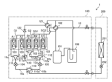
- FIG. 1 is a block diagram showing the configuration of an air conditioning apparatus according to a first embodiment.
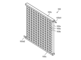
- 1 is a schematic perspective view of a heat exchanger of an air conditioning apparatus according to a first embodiment.
- FIG. 2 is a schematic plan view of an outdoor unit showing an example of the arrangement of heat exchangers within a housing of the outdoor unit of the air conditioning apparatus according to Embodiment 1.
- FIG. 11 is a block diagram showing the configuration of an air conditioning apparatus according to a second embodiment.
- 11 is a schematic plan view of an outdoor unit showing an example of the arrangement of heat exchangers within the housing of the outdoor unit of an air conditioning device according to embodiment 2.
- FIG. FIG. 11 is a block diagram showing the configuration of an air conditioning apparatus according to a third embodiment.
- 13 is a schematic plan view of an outdoor unit showing an example of the arrangement of heat exchangers within the housing of the outdoor unit of an air-conditioning apparatus according to embodiment 3.
- FIG. 1 is a block diagram showing the configuration of an air conditioner 1 according to the first embodiment.
- FIG. 2 is a schematic perspective view of a heat exchanger 103 of the air conditioner 1 according to the first embodiment.
- the air conditioner 1 includes an outdoor unit 100 and an indoor unit 200.
- the outdoor unit 100 includes a compressor 101, a four-way valve 102, a plurality of heat exchangers 103, a first flow control valve 104, a second flow control valve 105, an accumulator 106, and an outdoor blower 107 (see FIG. 3 described later).
- the outdoor unit 100 also includes a first branch section 110, a second branch section 111, and a third branch section 112.
- the outdoor unit 100 includes an on-off valve 120, a flow path switching valve 121, and a check valve 122.
- the indoor unit 200 includes a heat exchanger 201, a pressure reducing device 202, and an indoor blower (not shown).
- the air conditioning device 1 comprises a compressor 101, a four-way valve 102, multiple heat exchangers 103, a pressure reducing device 202, a heat exchanger 201, and an accumulator 106, which are connected by refrigerant piping to form a refrigerant circuit 10 through which the refrigerant circulates.
- the air conditioning device 1 performs heating operation and cooling operation by switching the four-way valve 102.
- the air conditioning device 1 is configured to be able to perform cooling operation or heating operation by switching the four-way valve 102, but it is sufficient if at least one of the operations can be performed.
- the air conditioning device 1 is required to be configured to perform an operation in which at least the multiple heat exchangers 103 function as evaporators.
- the compressor 101 draws in a refrigerant and compresses the drawn refrigerant to a high temperature and high pressure state.
- the compressor 101 is a positive displacement compressor that is equipped with an inverter device (not shown) and is capable of changing the operating frequency.
- the four-way valve 102 switches between heating and cooling operation by changing the direction of refrigerant flow in the refrigerant circuit 10.
- the air conditioning device 1 is equipped with five or more heat exchangers 103.
- Each of the heat exchangers 103 has the same configuration.
- the heat exchanger 103 has a plurality of flat tubes 103a extending in the vertical direction, a plurality of corrugated fins 103b arranged between adjacent flat tubes 103a, and a pair of headers 103c arranged at both ends of the extension direction of the plurality of flat tubes 103a.
- the heat exchanger 103 is not limited to the configuration shown in the figure.
- the heat exchanger 103 has flat tubes 103a as heat transfer tubes, but the heat transfer tubes may be circular tubes.
- the heat exchanger 103 has corrugated fins 103b as fins, but the fins may be plate fins.
- the plurality of heat exchangers 103 function as evaporators during heating operation and as condensers during cooling operation.
- the header 103c is a cylindrical body with both ends closed, and a space is formed inside through which the refrigerant flows.
- the header 103c has a rectangular cross-sectional shape, but this is not limited to a rectangular shape and may be a circular or elliptical shape, and can be modified as appropriate.
- the structure of the header 103c may be a stack of plate-shaped bodies with slits formed therein, other than the cylindrical body with both ends closed as described above.
- the pair of headers 103c may have different external shapes or cross-sectional shapes.
- One header 103c has an inlet 103d1 through which the refrigerant flows in, and the other header 103c has an outlet 103d2 through which the refrigerant flows out.
- the refrigerant that flows into one header 103c from the inlet 103d1 is distributed to each of the flat tubes 103a and flows from the bottom to the top of each flat tube 103a, then joins together in the other header 103c and flows out from the outlet 103d2.
- FIG. 1 shows an example in which the number of heat exchangers 103 is five, but the number of heat exchangers 103 may be five or more. In this specification, an example in which the number of heat exchangers 103 is five will be described. In addition, in the following description, upstream and downstream are based on the flow of the refrigerant when the heat exchanger 103 functions as an evaporator.
- the air conditioning device 1 has two types of heat exchangers 103 with different heat exchange capacities.
- the air conditioning device 1 has a plurality of heat exchangers 103, including heat exchanger A1, heat exchanger A2, heat exchanger B1, heat exchanger B2, and heat exchanger B3.
- Heat exchangers A1 and A2 have the same heat exchange capacity and refrigerant pressure loss.
- Heat exchangers B1, B2, and B3 have the same heat exchange capacity and refrigerant pressure loss.
- heat exchanger A is a general term for heat exchanger A1 and heat exchanger A2.
- Heat exchanger B is a general term for heat exchanger B1, heat exchanger B2, and heat exchanger B3.
- heat exchange capacity refers to the amount of heat exchanged between the refrigerant and air when the amount of air passing through a unit area of the heat exchanger is constant.
- Refrigerant pressure loss refers to the amount of pressure drop in the refrigerant that occurs from the inlet to the outlet of the heat exchanger 103.
- the heat exchange capacity of heat exchanger A is different from the heat exchange capacity of heat exchanger B. If the heat exchange capacity of heat exchanger A is Q1 and the heat exchange capacity of heat exchanger B is Q2, then as an example, they have the relationship Q1>Q2.
- the refrigerant pressure loss is greater in a heat exchanger with a larger heat exchange capacity than in a heat exchanger with a smaller heat exchange capacity. Therefore, the refrigerant pressure loss of heat exchanger A is greater than the refrigerant pressure loss of heat exchanger B.
- each heat exchanger 103 is not limited to having the same heat exchanger structure.
- heat exchanger A and heat exchanger B may have different heat exchanger structures.
- the first flow rate control valve 104 is, for example, an electronic expansion valve, and adjusts the refrigerant flow rate by setting the opening degree, and functions as a pressure reducing valve or expansion valve to reduce the pressure of the refrigerant and expand it.
- the first flow rate control valve 104 is provided in one of the two pipes 10a and 10b branched at the first branch section 110 described below, 10a.
- the opening degree of the first flow rate control valve 104 is controlled by a control device (not shown).
- the second flow control valve 105 is, for example, an electronic expansion valve, and adjusts the refrigerant flow rate by setting the opening degree, and functions as a pressure reducing valve or expansion valve to reduce the pressure of the refrigerant and expand it.
- the second flow control valve 105 is provided in the other pipe 10b of the two pipes 10a and 10b branched at the first branch section 110 described below.
- the opening degree of the second flow control valve 105 is controlled by a control device not shown.
- the accumulator 106 is provided on the suction side of the compressor 101 and is configured to separate the liquid refrigerant from the gas refrigerant, send the gas refrigerant to the compressor 101, and store the liquid refrigerant.
- the outdoor blower 107 (see Figure 3) is a fan that blows air and is composed of a centrifugal fan or a multi-blade fan, etc.
- the first branch section 110 is composed of a first two-branch pipe 110a.
- the first two-branch pipe 110a branches into two on the downstream side, one of which is connected to pipe 10a and the other to pipe 10b.
- the second branch section 111 is composed of one or more second two-branch pipes 111a.
- the second branch section 111 is composed of one second two-branch pipe 111a. Whether the second branch section 111 is composed of one two-branch pipe or multiple two-branch pipes depends on the number of heat exchangers 103 connected downstream of the second branch section 111.
- the number of second two-branch pipes 111a is the number of heat exchangers 103 connected downstream of the second branch section 111 minus one. In the illustrated example, since there are two heat exchangers 103 connected downstream of the second branch section 111, the number of second two-branch pipes 111a is one.
- the third branch section 112 is composed of one or more third two-branch pipes.
- the third branch section 112 is composed of two third two-branch pipes 112a and 112b. Whether the third branch section 112 is composed of one two-branch pipe or multiple two-branch pipes depends on the number of heat exchangers 103 connected downstream of the third branch section 112.
- the number of two-branch pipes is the number of heat exchangers 103 provided downstream of the third branch section 112 minus one. In the illustrated example, since the number of heat exchangers 103 connected downstream of the third branch section 112 is three, the number of two-branch pipes is two, and the third branch section 112 is composed of two third two-branch pipes 112a and 112b.
- the on-off valve 120, flow path switching valve 121, and check valve 122 are not relevant to the gist of this disclosure, so their description will be omitted.
- the heat exchanger 201 is, for example, a fin-and-tube type heat exchanger having a heat transfer tube and fins.
- the heat transfer tube is a flattened tube or a circular tube having a cross-sectional shape that is flat in one direction, such as an oval shape.
- the fins are, for example, corrugated fins or plate fins.
- the heat exchanger 201 functions as a condenser during heating operation and as an evaporator during cooling operation.
- the pressure reducing device 202 is, for example, an electronic expansion valve, and adjusts the refrigerant flow rate by setting the opening degree, and functions as a pressure reducing valve or an expansion valve to reduce the pressure and expand the refrigerant.
- FIG. 3 is a schematic plan view of the outdoor unit 100 showing an example of the arrangement of the heat exchanger 103 in the housing 100a of the outdoor unit 100 of the air conditioning device 1 according to the first embodiment.
- devices other than the heat exchanger 103 and the outdoor blower 107 are omitted.
- the housing 100a is formed in a rectangular parallelepiped shape and has a front wall 100a1, a rear wall 100a2, a left wall 100a3, a right wall 100a4, a bottom wall (not shown), and an upper wall (not shown). Air flows from the rear to the front in the housing 100a by the operation of the outdoor blower 107.
- the air conditioning device 1 has a configuration in which heat exchangers 103 of the same size are arranged in areas within the housing 100a that have the same amount of air passing through them. Airflow distribution occurs within the housing 100a, but the area within the housing 100a along the rear wall 100a2 has the same airflow distribution in the left-right direction. Additionally, within the housing 100a, the areas within the housing 100a along the left wall 100a3, the right wall 100a4, and the front wall 100a1 each have the same airflow distribution.
- the air conditioning device 1 has a configuration in which heat exchangers A1 and A2 are arranged side by side in the left-right direction along the rear wall 100a2, and this arrangement ensures that the airflow volumes passing through heat exchangers A1 and A2 are equal.
- the air conditioning device 1 also has a configuration in which heat exchangers B1, B2, and B3 are arranged, in that order, along the left wall 100a3, right wall 100a4, and front wall 100a1 within the housing 100a. This arrangement ensures that the airflow volumes passing through heat exchangers B1, B2, and B3 are equal.
- the air conditioning device 1 has the following distribution structure to realize optimal refrigerant flow rate distribution to the five heat exchangers 103.
- the five heat exchangers 103 are divided into a first group G1 and a second group G2.
- the five heat exchangers 103 are grouped into the first group G1 and the second group G2 so that heat exchangers with the same heat exchange capacity are in the same group. Therefore, among the five heat exchangers 103, the heat exchangers A1 and A2 with a heat exchange capacity of Q1 are classified into the first group G1, and the heat exchangers B1, B2, and B3 with a heat exchange capacity of Q2 are classified into the second group G2.
- optimal distribution of refrigerant means distributing the refrigerant according to the heat exchange capacity of the heat exchangers 103. More specifically, optimal distribution of refrigerant means first distributing a relatively large amount of refrigerant to a group with a large heat exchange capacity, and distributing a relatively small amount of refrigerant to a group with a small heat exchange capacity. Also, optimal distribution of refrigerant means distributing the refrigerant distributed to each group to each of the multiple heat exchangers 103 belonging to that group according to the heat exchange capacity of the heat exchanger 103. The air conditioning device 1 achieves this optimal distribution of refrigerant using a minimum number of flow control valves and two-branch pipes.
- the refrigerant is first distributed between the first group G1 and the second group G2 in a flow rate of 3:4.
- the air conditioning device 1 distributes the refrigerant between the first group G1 and the second group G2 by adjusting the opening degree of the first flow control valve 104 and the second flow control valve 105.
- the air conditioning device 1 then distributes the refrigerant to each of the multiple heat exchangers 103 that belong to the same group using a two-branch pipe.
- the multiple heat exchangers 103 are grouped according to their heat exchange capacity, and the heat exchangers 103 that belong to the same group have the same heat exchange capacity. Therefore, after the air conditioning device 1 distributes the refrigerant to each group using a flow control valve according to the total heat exchange capacity of the group, there is no need to adjust the flow rate using a flow control valve, and the air conditioning device 1 can optimally distribute the refrigerant to the heat exchangers 103 using a two-branch pipe. In other words, the air conditioning device 1 can optimally distribute the refrigerant to the multiple heat exchangers 103 using a minimum of two flow control valves and a number of two-branch pipes that is fewer than the number of heat exchangers 103.
- the air conditioning device 1 has a first branch 110 at the most upstream of the refrigerant distribution structure, and of the two pipes 10a and 10b branched off at the first branch 110, one pipe 10a is provided with a first flow control valve 104, and pipe 10b is provided with a second flow control valve 105.
- the first group G1 is connected downstream of the first flow control valve 104
- the second group G2 is connected downstream of the second flow control valve 105.
- the air conditioning device 1 has a second branch section 111 between the first flow control valve 104 and the first group G1. Since there are two heat exchangers 103 belonging to the first group G1, the second branch section 111 is composed of one second two-branch pipe 111a, one of which is branched into two, and pipe 11a is connected to one, and pipe 11b is connected to the other.
- the air conditioning device 1 branches the refrigerant flowing out of the first flow control valve 104 into two at the second two-branch pipe 111a, and distributes one to heat exchanger A1 via pipe 11a and the other to heat exchanger A2 via pipe 11b.
- the air conditioning device 1 distributes the refrigerant flowing out of the first flow control valve 104 in parallel to each of heat exchangers A1 and A2.
- heat exchangers A1 and A2 are heat exchangers 103 with the same heat exchange capacity and also have the same air flow rate, so there is no need to adjust the flow rate with a flow control valve, and flow rate distribution can be optimally performed using the second two-branch pipe 111a.
- the air conditioning device 1 is provided with a third branch section 112 between the second flow rate control valve 105 and the second group G2. Since there are three heat exchangers 103 belonging to the second group G2, the third branch section 112 is composed of two third bifurcated pipes 112a and 112b.
- the third bifurcated pipe 112a is connected upstream of the third bifurcated pipe 112b, and the third bifurcated pipe 112b is connected downstream of the third bifurcated pipe 112a.
- the air conditioning device 1 first branches the refrigerant flowing out of the second flow rate control valve 105 into two at the third bifurcated pipe 112a, and one of the refrigerant is further branched into two at the third bifurcated pipe 112b, for a total of three branches.
- the air conditioning device 1 has a configuration in which a third bifurcated pipe 112a branches into two at the third branch section 112, one of which is connected to pipe 12a and the other to pipe 12b, and the third bifurcated pipe 112b is connected to pipe 12a, which further branches into two.
- a total of three branched flow paths are formed at the third branch section 112 in the air conditioning device 1, and heat exchangers B1, B2, and B3 are connected to the three branched flow paths.
- the air conditioning device 1 distributes the refrigerant flowing out from the second flow control valve 105 in parallel to each of the heat exchangers B1, B2, and B3.
- the heat exchangers B1, B2, and B3 are heat exchangers 103 with the same heat exchange capacity and also have the same air flow rate, there is no need to adjust the flow rate using a flow control valve, and flow rate distribution can be performed using the third two-branch pipes 112a and 112b.
- the number of heat exchangers 103 is five, two are classified into the first group G1, and three are classified into the second group G2, but this classification is not limited.
- the number of heat exchangers 103 may be five, three are classified into the first group G1, and two are classified into the second group G2.
- the number of heat exchangers 103 is not limited to five as described above, and may be five or more. Therefore, for example, the number of heat exchangers 103 may be six, three are classified into the first group G1, and three are classified into the second group G2, or two are classified into the first group G1, and four are classified into the second group G2.
- the air conditioning device 1 distributes the refrigerant to each heat exchanger 103 using two flow rate adjustment valves and four two-branch pipes.
- the air conditioner 1 configured as described above is capable of heating or cooling operation by switching the four-way valve 102.
- the heat exchanger 201 functions as a condenser
- the heat exchanger 103 functions as an evaporator
- heating operation is performed.
- the heat exchanger 201 functions as an evaporator
- the heat exchanger 103 functions as a condenser
- cooling operation is performed.
- the four-way valve 102 is switched to the state shown by the solid line in FIG. 1.
- the refrigerant compressed by the compressor 101 becomes a high-temperature, high-pressure gas refrigerant, passes through the four-way valve 102, and flows into the heat exchanger 201.
- the refrigerant that flows into the heat exchanger 201 exchanges heat with the indoor air, condenses, and liquefies. At this time, the indoor air is heated by the refrigerant, and the heated indoor air is supplied to the indoor space to heat the room.
- the liquefied refrigerant is depressurized by the pressure reducing device 202 to become a gas-liquid two-phase state, and is branched at the first branch section 110, the second branch section 111, and the third branch section 112 to flow into each of the heat exchangers 103.
- Each refrigerant that flows into each of the heat exchangers 103 exchanges heat with the outdoor air, evaporates, and gasifies. After being merged, each gasified refrigerant passes through the four-way valve 102 and the accumulator 106 and returns to the compressor 101.
- the air conditioning device 1 Since the air conditioning device 1 has the above-mentioned refrigerant distribution structure, optimal refrigerant flow distribution is performed in each heat exchanger 103. This allows the air conditioning device 1 to improve heat exchange efficiency compared to a configuration that does not have the above-mentioned refrigerant distribution structure.
- the four-way valve 102 is switched to the state shown by the dotted line in Fig. 1.
- the refrigerant compressed by the compressor 101 becomes a high-temperature, high-pressure gas refrigerant and passes through the four-way valve 102.
- the gas refrigerant that has passed through the four-way valve 102 is distributed to and passes through heat exchangers B1, B2, and B3, then merges and passes through the on-off valve 120, and is distributed to and passes through heat exchangers A1 and A2.
- the refrigerant that has passed through heat exchangers B and A passes through first flow control valve 104, and is then depressurized by pressure reducing device 202.
- the depressurized refrigerant flows into the heat exchanger 201.
- the refrigerant that flows into the heat exchanger 201 exchanges heat with the indoor air and is gasified by dissipating heat.
- the indoor air is cooled by the refrigerant, and the cooled indoor air is supplied to the indoor space to cool the room.
- the gasified refrigerant passes through the four-way valve 102 and the accumulator 106 and returns to the compressor 101.
- the air conditioning device 1 includes a refrigerant circuit 10 having five or more heat exchangers 103 and through which a refrigerant circulates.
- the refrigerant circuit 10 includes a first branch section 110, a first flow control valve 104, a second flow control valve 105, a second branch section 111, and a third branch section 112.
- the first branch section 110 is configured with one two-branch pipe 110a.
- the first flow control valve 104 is provided in one pipe 10a of two pipes 10a and 10b branched at the first branch section 110.
- the second flow control valve 105 is provided in the other pipe 10b of two pipes 10a and 10b branched at the first branch section 110.
- the second branch section 111 is configured with one second two-branch pipe 111a.
- the third branch section 112 is configured with two third two-branch pipes 112a and 112b.
- the five or more heat exchangers 103 are divided into a first group G1 and a second group G2 such that heat exchangers with the same heat exchange capacity are in the same group.
- the first group G1 is connected downstream of the first flow control valve 104, and the second group G2 is connected downstream of the second flow control valve 105.
- a second branching section 111 is provided between the first flow control valve 104 and the first group G1, and the refrigerant flowing out from the first flow control valve 104 is distributed in parallel to each of the heat exchangers 103 belonging to the first group G1.
- a third branching section 112 is provided between the second flow control valve 105 and the second group G2, and the refrigerant flowing out from the second flow control valve 105 is distributed in parallel to each of the heat exchangers 103 belonging to the second group G2.
- the air conditioning device 1 can achieve optimal refrigerant flow distribution at low cost by reducing the number of flow control valves to two and using a two-branch pipe compared to a configuration with the same number of flow control valves as the number of heat exchangers.
- Embodiment 2 The following description will focus on the configuration of the second embodiment that is different from the first embodiment, and the configuration that is not described in the second embodiment is the same as that in the first embodiment.
- FIG. 4 is a block diagram showing the configuration of an air conditioning device 1 according to embodiment 2.
- FIG. 5 is a schematic plan view of the outdoor unit 100 showing an example of the arrangement of the heat exchanger 103 within the housing 100a of the outdoor unit 100 of the air conditioning device 1 according to embodiment 2.
- the air conditioning device 1 of the above-mentioned embodiment 1 has an effective structure in that the heat exchanger B1 and the heat exchanger B2 have the same heat exchange capacity, and therefore the refrigerant can be distributed to them by the third two-branch pipe 112b rather than by a flow control valve.
- heat exchanger B3 is also considered, since heat exchangers B1, B2, and B3 have the same heat exchange capacity, it is desirable that the refrigerant be distributed in a 1:1:1 ratio.
- the air conditioning device 1 of embodiment 1 if the refrigerant is distributed equally in each of the third bifurcated pipe 112a and the third bifurcated pipe 112b, the refrigerant will be distributed to heat exchanger B1, heat exchanger B2, and heat exchanger B3 at a distribution ratio of 1:1:2.
- the air conditioning device 1 is required to distribute the refrigerant taking into account the refrigerant pressure loss of the heat exchanger 103.
- Embodiment 2 is an embodiment that aims to improve on the above points. Note that, in the following, for simplicity of explanation, it is assumed that heat exchangers 103 with the same heat exchange capacity also have the same refrigerant pressure loss.
- the air conditioning apparatus 1 of the second embodiment has three types of heat exchangers 103 with different heat exchange capacities.
- the air conditioning apparatus 1 has a plurality of heat exchangers 103, including heat exchanger A1, heat exchanger A2, heat exchanger B1, heat exchanger B2, and heat exchanger C1.
- the heat exchange capacities Q1 of heat exchangers A1 and A2, Q2 of heat exchangers B1 and B2, and Q3 of heat exchanger C1 are different from one another, and in the illustrated example, Q3>Q1>Q2.
- the air conditioning device 1 of embodiment 2 has a configuration in which, so to speak, heat exchanger C1, which has a heat exchange capacity and refrigerant pressure loss that match the refrigerant distribution ratio, is selected for heat exchanger B3 out of heat exchangers B1, B2, and B3 of embodiment 1.
- Heat exchanger C1 has the total heat exchange capacity of heat exchangers B1 and B2, and has the total refrigerant pressure loss of heat exchangers B1 and B2.
- the rest of the configuration of the air conditioning device 1 of embodiment 2 is the same as that of embodiment 1.
- the air conditioning device 1 of embodiment 2 has a ratio of the heat exchange capacity between heat exchanger B1, heat exchanger B2, and heat exchanger C1, and a ratio of the refrigerant pressure loss of 1:1:2, which can be adjusted to match the refrigerant distribution ratio, allowing for more optimal refrigerant distribution.
- the air-conditioning apparatus 1 of the second embodiment has the following distribution structure to realize optimal refrigerant flow rate distribution to each of the five heat exchangers 103. Below, the air-conditioning apparatus 1 of the second embodiment will be described, focusing on the differences from the refrigerant distribution structure of the first embodiment.
- the air conditioning device 1 of the second embodiment is divided into a first group G1 and a second group G2 so that refrigerants with the same heat exchange capacity are in the same group, as in the first embodiment.
- the first subgroup SG1 and the second subgroup SG2 are configured so that the refrigerant branched into two by the third two-way branch valve 112a is distributed and flows.
- one type of heat exchanger 103 is classified into the first group G1, and the other two types of heat exchangers 103 are classified into the second group G2.
- the heat exchangers A1 and A2 with a heat exchange capacity of Q1 are classified into the first group G1, and the heat exchangers B1 and B2 with a heat exchange capacity of Q2 and the heat exchanger C1 with a heat exchange capacity of Q3 are classified into the second group G2.
- the heat exchangers B1, B2, and C1 belonging to the second group G2 are divided into a first subgroup SG1 and a second subgroup SG2 according to the refrigerant pressure loss.
- the heat exchangers B1, B2, and C1 belonging to the second group G2 are subgrouped so that the total refrigerant pressure loss of the first subgroup SG1 is the same as the total refrigerant pressure loss of the second subgroup SG2.
- the total refrigerant pressure loss of the first subgroup SG1 is set to be the same as the total refrigerant pressure loss of the second subgroup SG2.
- heat exchangers B1 and B2 are classified into a first subgroup SG1, and heat exchanger C1 is classified into a second subgroup SG2.
- the total refrigerant pressure loss of the first subgroup SG1 is the sum of the refrigerant pressure loss of heat exchanger B1 and the refrigerant pressure loss of heat exchanger B2.
- the only heat exchanger 103 that belongs to the second subgroup SG2 is heat exchanger C1, so the total refrigerant pressure loss of the second subgroup SG2 is the refrigerant pressure loss of heat exchanger C1.
- the air conditioning apparatus 1 can obtain the same effects as in embodiment 1, and because the total refrigerant pressure loss of the first subgroup SG1 and the total refrigerant pressure loss of the second subgroup SG2 are set to be the same, the following effects can be obtained:
- the air conditioning apparatus 1 passes the refrigerant, which has been equally divided into two flow rates in the third two-branch pipe 112a, through the first subgroup SG1 and the second subgroup SG2, which have the same refrigerant pressure loss, and therefore can perform more optimal flow rate distribution compared to embodiment 1.
- the first group G1 may have this configuration, or both the first group G1 and the second group G2 may have the above configuration.
- the multiple heat exchangers 103 belonging to at least one of the first group G1 and the second group G2 have the following configuration (1).
- the refrigerant is divided into a first subgroup SG1 and a second subgroup SG2, and the refrigerant branched into two is distributed to flow through the first subgroup SG1 and the second subgroup SG2.
- the total refrigerant pressure loss of the first subgroup SG1 is set to be equal to the total refrigerant pressure loss of the second subgroup SG2.
- a plurality of heat exchangers 103 belonging to at least one other than the first group G1 and the second group G2 have the configuration (1) above or the configuration (2) below.
- the heat exchange capacities are set to be the same for each other.
- Embodiment 3 The following description will focus on the configuration of the third embodiment that differs from the second embodiment, and the configuration not described in the third embodiment is the same as that in the second embodiment.
- FIG. 6 is a block diagram showing the configuration of an air conditioning device 1 according to embodiment 3.
- FIG. 7 is a schematic plan view of the outdoor unit 100 showing an example of the arrangement of the heat exchanger 103 within the housing 100a of the outdoor unit 100 of the air conditioning device 1 according to embodiment 3.
- the air conditioning device 1 of the above-mentioned embodiment 2 sets the total refrigerant pressure loss of the first subgroup SG1 and the total refrigerant pressure loss of the second subgroup SG2 to be the same, thereby making the refrigerant pressure loss of the two branch flow paths downstream of the third bifurcated pipe 112a the same.
- the air conditioning device 1 of embodiment 3 uses a resistor 130 to make the refrigerant pressure loss of the two branch flow paths downstream of the third bifurcated pipe 112a the same.
- the air conditioning apparatus 1 of embodiment 3 has three types of heat exchangers 103 with different heat exchange capacities, similar to embodiment 2.
- the air conditioning apparatus 1 has a plurality of heat exchangers 103, namely heat exchanger A1, heat exchanger A2, heat exchanger B1, heat exchanger B2, and heat exchanger C2.
- the heat exchange capacity Q1 of heat exchangers A1 and A2, the heat exchange capacity Q2 of heat exchangers B1 and B2, and the heat exchange capacity Q4 of heat exchanger C2 are different from one another, and in the illustrated example, Q1>Q2>Q4.
- the air conditioning apparatus 1 of embodiment 3 differs in that the heat exchange capacity and refrigerant pressure loss of heat exchanger C2 are smaller than those of heat exchanger C1, and that a resistor 130 is provided.
- the heat exchanger C2 belonging to the second subgroup SG2 has a smaller refrigerant pressure loss than the heat exchanger C1 of embodiment 2, and therefore the total refrigerant pressure loss of the second subgroup SG2 is smaller than the total refrigerant pressure loss of the first subgroup SG1.
- the resistor 130 acts as a resistance to the flow of the refrigerant and adjusts the difference between the total refrigerant pressure loss of the first subgroup SG1 and the total refrigerant pressure loss of the second subgroup SG2.
- the resistor 130 has a refrigerant pressure loss equivalent to the difference between the total refrigerant pressure loss of the heat exchangers B1 and B2 and the refrigerant pressure loss of the heat exchanger C2.
- the air conditioning device 1 has the same refrigerant pressure loss in the two branch flow paths downstream of the third two-branch pipe 112a.
- the resistor 130 is, for example, a thin tube in the pipe 12b having a diameter smaller than the diameter of the pipe 12b, or a capillary tube.
- the resistor 130 may be a valve provided in the pipe.
- the air conditioning apparatus 1 of embodiment 3 differs from the air conditioning apparatus 1 of embodiment 2 in that it is provided with a resistor 130, but the other refrigerant distribution structures are similar to those of embodiment 2.
- the air conditioning apparatus 1 of embodiment 3 is provided with the resistor 130 upstream of the second subgroup SG2, which is the subgroup with smaller refrigerant pressure loss, specifically in the pipe 12b.
- the second group G2 is divided into a first subgroup SG1 and a second subgroup SG2, and the two branched refrigerant flows distributed between the first subgroup SG1 and the second subgroup SG2.
- the total refrigerant pressure loss of the first subgroup SG1 and the total refrigerant pressure loss of the second subgroup SG2 are different, and a resistor 130 is provided upstream of the subgroup with the smaller total refrigerant pressure loss to adjust the difference in the total refrigerant pressure loss.
- the air conditioning device 1 can obtain the same effect as in embodiment 2. More specifically, the air conditioning device 1 is provided with the resistor 130, which makes the refrigerant pressure loss in the two branch flow paths downstream of the third bifurcated pipe 112a the same. Therefore, the air conditioning device 1 can pass the refrigerant, which is divided into two equal flow rates in the third bifurcated pipe 112a, through two branch flow paths with the same refrigerant pressure loss, and can perform more optimal refrigerant flow rate distribution compared to embodiment 1, as in embodiment 2.
- the resistor 130 may be provided in the first subgroup SG1. Furthermore, the resistor 130 may be provided in the first group G1 when the number of heat exchangers 103 belonging to the first group G1 is three or more.
- the multiple heat exchangers 103 belonging to at least one of the first group G1 and the second group G2 have the following configuration (1).
- the refrigerant is divided into a first subgroup SG1 and a second subgroup SG2, and the refrigerant branched into two is distributed to flow through the first subgroup SG1 and the second subgroup SG2.
- a resistor 130 for adjusting the difference between the total refrigerant pressure loss of the first subgroup SG1 and the total refrigerant pressure loss of the second subgroup SG2 is provided upstream of the subgroup with the smaller total refrigerant pressure loss.
- a plurality of heat exchangers 103 belonging to at least one other than the first group G1 and the second group G2 have the configuration (1) above or the configuration (2) below.
- the heat exchange capacities are set to be the same for each other.
- 1 air conditioning device 10 refrigerant circuit, 10a piping, 10b piping, 11a piping, 11b piping, 12a piping, 12b piping, 100 outdoor unit, 100a housing, 100a1 front wall, 100a2 rear wall, 100a3 left wall, 100a4 right wall, 101 compressor, 102 four-way valve, 103 heat exchanger, 103a flat tube, 103b corrugated fin, 103c header, 103d1 inlet, 103d2 outlet, 104 first flow control valve, 105 second flow control valve, 106 accumulator, 107 outdoor blower, 110 first branch, 110a first two-branch pipe, 111 second branch Branch, 111a second two-way branch pipe, 112 third branch, 112a third two-way branch valve, 112b third two-way branch valve, 120 on-off valve, 121 flow path switching valve, 122 check valve, 130 resistor, 200 indoor unit, 201 heat exchanger, 202 pressure reducing device, A heat exchanger, A1 heat exchanger, A2 heat
Landscapes
- Engineering & Computer Science (AREA)
- Mechanical Engineering (AREA)
- General Engineering & Computer Science (AREA)
- Physics & Mathematics (AREA)
- Thermal Sciences (AREA)
- Chemical & Material Sciences (AREA)
- Combustion & Propulsion (AREA)
- Compression-Type Refrigeration Machines With Reversible Cycles (AREA)
Abstract
空気調和装置は、5つ以上の複数の熱交換器を有し、冷媒が循環する冷媒回路を備える。冷媒回路は、第1の2分岐管で構成された第1分岐部と、第1分岐部において分岐した2つの配管の一方に設けられた第1流量調整弁および他方に設けられた第2流量調整弁と、1または複数の第2の2分岐管で構成された第2分岐部と、1または複数の第3の2分岐管で構成された第3分岐部と、を有し、5つ以上の複数の熱交換器は、熱交換容量が同じもの同士が同じグループとなるように第1グループと第2グループとに分けられており、第1グループは第1流量調整弁の下流に接続され、第2グループは第2流量調整弁の下流に接続されており、第1流量調整弁から流出した冷媒が第1グループに属する複数の熱交換器のそれぞれに並列に冷媒が第2分岐部により分配されるように構成され、第2流量調整弁から流出した冷媒が第3分岐部により第2グループに属する複数の熱交換器のそれぞれに並列に冷媒が分配されるように構成されている。
Description
本開示は、冷媒が並列に分配されて流れる複数の熱交換器を備えた空気調和装置に関する。
従来、冷媒が並列に分配されて流れる複数の熱交換器を備えた空気調和装置がある(例えば、特許文献1参照)。特許文献1の空気調和装置は、室外機を構成する筐体内に複数の熱交換器を備え、複数の熱交換器のそれぞれに並列に冷媒を流す構成が開示されている。
空気調和装置は、空調能力の大きい空気調和装置を実現しようとする場合、熱交換器の数を増加させる必要がある。しかし、空気調和装置は、熱交換器の数が増加すると、各熱交換器のそれぞれの熱交換容量を考慮した最適な冷媒の分配が難しくなる。熱交換容量を考慮した最適な冷媒の分配を実現するには、各熱交換器のそれぞれに対応して流量調整弁を設ける構成とする方法が考えられる。しかし、この方法では、熱交換器の数だけ流量調整弁が必要となり、高コストとなる。
特許文献1の空気調和装置は、熱交換器の台数よりも流量調整弁の数を減らした構成について開示されているが、各熱交換器へ冷媒の最適な流量分配について検討されていない。
本開示は、上述の課題を解決するためのものであり、流量調整弁の数を減らしつつ、低コストで冷媒の最適な流量分配を実現できる空気調和装置を提供することを目的とするものである。
本開示に係る空気調和装置は、5つ以上の複数の熱交換器を有し、冷媒が循環する冷媒回路を備え、冷媒回路は、第1の2分岐管で構成された第1分岐部と、第1分岐部において分岐した2つの配管の一方に設けられた第1流量調整弁および他方に設けられた第2流量調整弁と、1または複数の第2の2分岐管で構成された第2分岐部と、1または複数の第3の2分岐管で構成された第3分岐部と、を有し、5つ以上の複数の熱交換器は、熱交換容量が同じもの同士が同じグループとなるように第1グループと第2グループとに分けられており、第1グループは第1流量調整弁の下流に接続され、第2グループは第2流量調整弁の下流に接続されており、第1流量調整弁と第1グループとの間に第2分岐部が設けられ、第1流量調整弁から流出した冷媒が第1グループに属する複数の熱交換器のそれぞれに並列に冷媒が分配されるように構成され、第2流量調整弁と第2グループとの間に第3分岐部が設けられ、第2流量調整弁から流出した冷媒が第2グループに属する複数の熱交換器のそれぞれに並列に冷媒が分配されるように構成されているものである。
本開示に係る空気調和装置は、5つ以上の複数の熱交換器を有し、冷媒が循環する冷媒回路を備え、冷媒回路は、第1の2分岐管で構成された第1分岐部と、第1分岐部において分岐した2つの配管の一方に設けられた第1流量調整弁および他方に設けられた第2流量調整弁と、1または複数の第2の2分岐管で構成された第2分岐部と、1または複数の第3の2分岐管で構成された第3分岐部と、を有し、5つ以上の複数の熱交換器は、熱交換容量の異なる3種類の熱交換器であり、熱交換容量が同じもの同士が同じグループとなるように第1グループと第2グループとに分けられ、第1グループは第1流量調整弁の下流に接続され、第2グループは第2流量調整弁の下流に接続されており、第1流量調整弁と第1グループとの間に第2分岐部が設けられ、第1流量調整弁から流出した冷媒が第1グループに属する複数の熱交換器のそれぞれに並列に冷媒が分配されるように構成され、第2流量調整弁と第2グループとの間に第3分岐部が設けられ、第2流量調整弁から流出した冷媒が第2グループに属する複数の熱交換器のそれぞれに並列に冷媒が分配されるように構成されており、第1グループおよび第2グループの少なくとも一方に属する複数の熱交換器は、(1)の構成を有し、第1グループおよび第2グループの少なくとも一方以外に属する複数の熱交換器は、(1)の構成または(2)の構成を有するものである。
(1)第1サブグループと第2サブグループとに分けられ、2つに分岐した冷媒が第1サブグループと第2サブグループと分配されて流れるように構成され、第1サブグループの合計の冷媒圧力損失と第2サブグループの合計の冷媒圧力損失とが同じに設定されている。
(2)熱交換容量が互いに同じに設定されている。
(1)第1サブグループと第2サブグループとに分けられ、2つに分岐した冷媒が第1サブグループと第2サブグループと分配されて流れるように構成され、第1サブグループの合計の冷媒圧力損失と第2サブグループの合計の冷媒圧力損失とが同じに設定されている。
(2)熱交換容量が互いに同じに設定されている。
本開示に係る空気調和装置は、5つ以上の複数の熱交換器を有し、冷媒が循環する冷媒回路を備え、冷媒回路は、第1の2分岐管で構成された第1分岐部と、第1分岐部において分岐した2つの配管の一方に設けられた第1流量調整弁および他方に設けられた第2流量調整弁と、1または複数の第2の2分岐管で構成された第2分岐部と、1または複数の第3の2分岐管で構成された第3分岐部と、第1流量調整弁または第2流量調整弁の下流に設けられ、冷媒の流れの抵抗となる抵抗体と、を有し、5つ以上の複数の熱交換器は、熱交換容量の異なる3種類の熱交換器であり、熱交換容量が同じもの同士が同じグループとなるように第1グループと第2グループとに分けられ、第1グループは第1流量調整弁の下流に接続され、第2グループは第2流量調整弁の下流に接続されており、第1流量調整弁と第1グループとの間に第2分岐部が設けられ、第1流量調整弁から流出した冷媒が第1グループに属する複数の熱交換器のそれぞれに並列に冷媒が分配されるように構成され、第2流量調整弁と第2グループとの間に第3分岐部が設けられ、第2流量調整弁から流出した冷媒が第2グループに属する複数の熱交換器のそれぞれに並列に冷媒が分配されるように構成されており、第1グループに属する複数の熱交換器および第2グループに属する複数の熱交換器の少なくとも一方は、(1)の構成を有し、第1グループおよび第2グループの少なくとも一方以外に属する複数の熱交換器は、(1)の構成または(2)の構成を有するものである。
(1)第1サブグループと第2サブグループとに分けられ、2つに分岐した冷媒が第1サブグループと第2サブグループと分配されて流れるように構成され、第1サブグループの合計の冷媒圧力損失と第2サブグループの合計の冷媒圧力損失とのうち、合計の冷媒圧力損失が小さい方のサブグループの上流に抵抗体が設けられている。
(2)熱交換容量が互いに同じに設定されている。
(1)第1サブグループと第2サブグループとに分けられ、2つに分岐した冷媒が第1サブグループと第2サブグループと分配されて流れるように構成され、第1サブグループの合計の冷媒圧力損失と第2サブグループの合計の冷媒圧力損失とのうち、合計の冷媒圧力損失が小さい方のサブグループの上流に抵抗体が設けられている。
(2)熱交換容量が互いに同じに設定されている。
本開示に係る空気調和装置は、5つ以上の複数の熱交換器が、熱交換容量が同じもの同士が同じグループとなるように第1グループと第2グループとに分けられ、各グループへの流量分配については第1流量調整弁と第2流量調整弁とを用いて行う。第1流量調整弁および第2流量調整弁よりも下流の各熱交換器への流量分配については2分岐管を用いて行う。これにより、空気調和装置は、 流量調整弁の数を減らしつつ、低コストで冷媒の最適な流量分配を実現できる。
以下、図面を参照して、本開示の実施の形態について説明する。なお、各図中、同一または相当する部分には、同一符号を付して、その説明を適宜省略または簡略化する。また、明細書全文に表わされている構成要素の形態は、あくまでも例示であって、これらの記載に限定されるものではない。また、理解を容易にするために方向あるいは位置を表す用語(例えば「右」、「左」、「前」および「後」等)を適宜用いる。しかし、これらの表記は、説明の便宜上、そのように記載しているだけであって、装置あるいは部品の配置および向きを限定するものではない。
実施の形態1.
[空気調和装置1の全体構成]
図1は、実施の形態1に係る空気調和装置1の構成を示すブロック図である。図2は、実施の形態1に係る空気調和装置1の熱交換器103の概略斜視図である。空気調和装置1は、室外機100と室内機200とを備えている。室外機100は、圧縮機101と、四方弁102と、複数の熱交換器103と、第1流量調整弁104と、第2流量調整弁105と、アキュムレータ106と、室外送風機107(後述の図3参照)と、を備えている。また、室外機100は、第1分岐部110と、第2分岐部111と、第3分岐部112と、を備えている。室外機100は、開閉弁120と、流路切替弁121と、逆止弁122と、を備えている。室内機200は、熱交換器201と、減圧装置202と、室内送風機(図示せず)と、を備えている。
[空気調和装置1の全体構成]
図1は、実施の形態1に係る空気調和装置1の構成を示すブロック図である。図2は、実施の形態1に係る空気調和装置1の熱交換器103の概略斜視図である。空気調和装置1は、室外機100と室内機200とを備えている。室外機100は、圧縮機101と、四方弁102と、複数の熱交換器103と、第1流量調整弁104と、第2流量調整弁105と、アキュムレータ106と、室外送風機107(後述の図3参照)と、を備えている。また、室外機100は、第1分岐部110と、第2分岐部111と、第3分岐部112と、を備えている。室外機100は、開閉弁120と、流路切替弁121と、逆止弁122と、を備えている。室内機200は、熱交換器201と、減圧装置202と、室内送風機(図示せず)と、を備えている。
空気調和装置1は、圧縮機101と、四方弁102と、複数の熱交換器103と、減圧装置202と、熱交換器201と、アキュムレータ106と、が冷媒配管で接続され、冷媒が循環する冷媒回路10を構成している。空気調和装置1は、四方弁102の切り替えにより、暖房運転と冷房運転とを行う。なお、空気調和装置1は四方弁102の切り替えにより冷房運転または暖房運転が可能に構成されているが、少なくともどちらか一方の運転ができればよい。空気調和装置1は、少なくとも複数の熱交換器103が蒸発器として機能する運転を行う構成であればよい。
(室外機100)
圧縮機101は、冷媒を吸入し、吸入した冷媒を圧縮して高温且つ高圧の状態にするものである。圧縮機101は、インバータ装置(図示せず)を備え、運転周波数を変化させることが可能な容積式圧縮機で構成されている。
圧縮機101は、冷媒を吸入し、吸入した冷媒を圧縮して高温且つ高圧の状態にするものである。圧縮機101は、インバータ装置(図示せず)を備え、運転周波数を変化させることが可能な容積式圧縮機で構成されている。
四方弁102は、冷媒回路10における冷媒の流れ方向を切り替えることで、暖房運転と冷房運転とを切り替えるものである。
空気調和装置1は、5つ以上の複数の熱交換器103を備えている。複数の熱交換器103のそれぞれは同じ構成である。熱交換器103は、図2に示すように、上下方向に延伸する複数の扁平管103aと、隣り合う扁平管103a同士の間に配置された複数のコルゲートフィン103bと、複数の扁平管103aの延伸方向の両端に配置された一対のヘッダ103cと、を有する。なお、熱交換器103は、図示の構成に限られたものではない。図示の例では、熱交換器103は、伝熱管として扁平管103aを備えているが、伝熱管は円管でもよい。また、熱交換器103は、フィンとしてコルゲートフィン103bを備えているが、フィンはプレートフィンでもよい。複数の熱交換器103は、暖房運転時に蒸発器として機能し、冷房運転時に凝縮器として機能する。
ヘッダ103cは、両端が閉じられた筒状体であり、内部には冷媒が流通する空間が形成されている。ヘッダ103cは、図示の例では、断面形状が矩形状の例を示しているが、矩形状に限られたものではなく、円形状または楕円状でもよいし、適宜変更することができる。また、ヘッダ103cの構造は、上述した、両端が閉じられた筒状体で構成する以外にも、例えば、スリットが形成された板状体を積層させたものでもよい。また、一対のヘッダ103cは、互いに、外形または断面形状が異なる構成でもよい。
一方のヘッダ103cには、冷媒が流入する流入口103d1が設けられ、他方のヘッダ103cには、冷媒が流出する流出口103d2が設けられている。流入口103d1から一方のヘッダ103cに流入した冷媒は、複数の扁平管103aのそれぞれに分配されて各扁平管103aを下端から上端に向かって流れた後、他方のヘッダ103cで合流し、流出口103d2から流出する。
ここで、図1では、熱交換器103の数が5つである例が示されているが、熱交換器103の数は5つ以上であればよい。本明細書では、熱交換器103の数が5つである例を説明する。また、以下の説明において、上流、下流とは、熱交換器103が蒸発器として機能するときの冷媒の流れに基づくものとする。
実施の形態1では、空気調和装置1は、熱交換容量の異なる2種類の熱交換器103を有する。空気調和装置1は、複数の熱交換器103として、熱交換器A1と、熱交換器A2と、熱交換器B1と、熱交換器B2と、熱交換器B3と、を有する。熱交換器A1およびA2は互いに、熱交換容量および冷媒圧力損失が同じ熱交換器である。熱交換器B1、B2およびB3は互いに、熱交換容量および冷媒圧力損失が同じ熱交換器である。以下において、熱交換器Aは、熱交換器A1および熱交換器A2の総称である。また、熱交換器Bは、熱交換器B1、熱交換器B2および熱交換器B3の総称である。
ここで、熱交換容量とは、熱交換器の単位面積を通過する風量が一定である場合の、冷媒と空気との間で行われる熱交換量である。冷媒圧力損失とは、熱交換器103の入口から出口に至るまでの間に生じる冷媒の圧力低下量である。なお、本明細書における「同じ」の表現には、厳密に同じ場合に限られず、実質的に同じ場合も含まれる。
熱交換器Aの熱交換容量と熱交換器Bの熱交換容量とは異なる。熱交換器Aの熱交換容量がQ1、熱交換器Bの熱交換容量がQ2であるとすると、ここでは一例として、Q1>Q2の関係を有する。冷媒圧力損失は、熱交換容量が多い熱交換器の方が熱交換容量が少ない熱交換器よりも大きくなる。よって、熱交換器Aの冷媒圧力損失は熱交換器Bの冷媒圧力損失よりも大きい。
ここで、本明細書では、各熱交換器103の熱交換器構造自体は同じであり、正面から見たときの外形の大きさが異なることで熱交換容量が異なっているものとする。よって、「熱交換器103の大きさが大きい」とは、「熱交換容量が大きい」と同義である。但し、各熱交換器103は熱交換器構造が同じ構造に限られたものではない。例えば、熱交換器Aと熱交換器Bとで熱交換器構造が異なっていてもよい。
第1流量調整弁104は、例えば電子膨張弁により構成され、開度が設定されることで冷媒流量を調整し、減圧弁または膨張弁として機能して冷媒を減圧して膨張させるものである。第1流量調整弁104は、後述の第1分岐部110において分岐した2つの配管10aおよび10bの一方の配管10aに設けられている。第1流量調整弁104の開度は、図示しない制御装置によって制御される。
第2流量調整弁105は、例えば電子膨張弁により構成され、開度が設定されることで冷媒流量を調整し、減圧弁または膨張弁として機能して冷媒を減圧して膨張させるものである。第2流量調整弁105は、後述の第1分岐部110において分岐した2つの配管10aおよび10bの他方の配管10bに設けられている。第2流量調整弁105の開度は、図示しない制御装置によって制御される。
アキュムレータ106は、圧縮機101の吸入側に設けられており、液冷媒とガス冷媒とを分離して、ガス冷媒を圧縮機101に送出し、液冷媒を溜めるように構成されている。
室外送風機107(図3参照)は、空気を送風するファンであり、遠心ファンまたは多翼ファン等から構成されている。
第1分岐部110は、第1の2分岐管110aで構成されている。第1の2分岐管110aは、下流側が2つに分岐し、一方に配管10aが接続され、他方に配管10bが接続されている。
第2分岐部111は、1または複数の第2の2分岐管111aで構成されている。図示の例では、第2分岐部111は、1つの第2の2分岐管111aで構成されている。第2分岐部111が1つの2分岐管で構成されるか、複数の2分岐管で構成されるかは、第2分岐部111の下流に接続される熱交換器103の数に寄る。第2の2分岐管111aの数は、第2分岐部111の下流に接続される熱交換器103の数から1を引いた数となる。図示の例では、第2分岐部111の下流に接続される熱交換器103の数が2つであるため、第2の2分岐管111aの数は1つとなっている。
第3分岐部112は、1または複数の第3の2分岐管で構成されている。図示の例では、第3分岐部112は、2つの第3の2分岐管112aおよび112bで構成されている。第3分岐部112が1つの2分岐管で構成されるか、複数の2分岐管で構成されるかは、第3分岐部112の下流に接続される熱交換器103の数に寄る。2分岐管の数は、第3分岐部112の下流に設けられる熱交換器103の数から1を引いた数となる。図示の例では、第3分岐部112の下流に接続される熱交換器103の数が3つであるため、2分岐管の数は2つであり、第3分岐部112は第3の2分岐管112aおよび112bの2つで構成されている。
開閉弁120、流路切替弁121および逆止弁122は、本開示の要旨と関係ないため、その説明を省略する。
(室内機200)
熱交換器201は、例えば伝熱管とフィンとを有するフィンアンドチューブ型熱交換器により構成されている。伝熱管は、長円形状等の一方向に扁平な断面形状を有する扁平管または円管で構成されている。フィンは、例えばコルゲートフィンまたはプレートフィンなどである。熱交換器201は、暖房運転時に凝縮器として機能し、冷房運転時に蒸発器として機能する。
熱交換器201は、例えば伝熱管とフィンとを有するフィンアンドチューブ型熱交換器により構成されている。伝熱管は、長円形状等の一方向に扁平な断面形状を有する扁平管または円管で構成されている。フィンは、例えばコルゲートフィンまたはプレートフィンなどである。熱交換器201は、暖房運転時に凝縮器として機能し、冷房運転時に蒸発器として機能する。
減圧装置202は、例えば電子膨張弁により構成され、開度が設定されることで冷媒流量を調整し、減圧弁または膨張弁として機能して冷媒を減圧して膨張させるものである。
(熱交換器103の配置)
図3は、実施の形態1に係る空気調和装置1の室外機100の筐体100a内における熱交換器103の配置例を示す室外機100の概略平面図である。図3において、熱交換器103および室外送風機107以外の機器の図示は省略している。筐体100aは、直方体状に形成され、前壁100a1と、後壁100a2と、左壁100a3と、右壁100a4と、底壁(図示せず)と、上壁(図示せず)とを有する。筐体100a内には、室外送風機107の運転により、空気が後方から前方に向かって流れる。
図3は、実施の形態1に係る空気調和装置1の室外機100の筐体100a内における熱交換器103の配置例を示す室外機100の概略平面図である。図3において、熱交換器103および室外送風機107以外の機器の図示は省略している。筐体100aは、直方体状に形成され、前壁100a1と、後壁100a2と、左壁100a3と、右壁100a4と、底壁(図示せず)と、上壁(図示せず)とを有する。筐体100a内には、室外送風機107の運転により、空気が後方から前方に向かって流れる。
空気調和装置1は、同じ大きさの熱交換器103が通過風量を同等とする筐体100a内の領域に配置された構成を有する。筐体100a内には気流の分布が生じるが、後壁100a2に沿う筐体100a内の領域は、左右方向において同一の気流分布を有する。また、筐体100a内において、左壁100a3と、右壁100a4と、前壁100a1とのそれぞれに沿う筐体100a内の各領域は、同一の気流分布を有する。
よって、図3の例では、空気調和装置1は、熱交換器A1およびA2が、後壁100a2に沿って左右方向に並んで配置された構成を有し、この配置により、熱交換器A1およびA2の通過風量が同等となるようにしている。また、空気調和装置1は、熱交換器B1と、熱交換器B2と、熱交換器B3とが、筐体100a内において、順に、左壁100a3と、右壁100a4と、前壁100a1と、に沿って配置された構成を有する。この配置により、熱交換器B1、B2およびB3の通過風量が同等となるようにしている。
[冷媒分配構造]
空気調和装置1は、5つの熱交換器103に最適な冷媒の流量分配を実現するために以下の分配構造を有する。図1に示すように、5つの熱交換器103は、第1グループG1と第2グループG2とに分けられる。実施の形態1では、5つの熱交換器103は、熱交換容量が同じもの同士が同じグループとなるように第1グループG1と第2グループG2とにグループ分けされている。よって、5つの熱交換器103のうち、熱交換容量がQ1の熱交換器A1およびA2は、第1グループG1に分類され、熱交換容量がQ2の熱交換器B1、B2およびB3は、第2グループG2に分類されている。
空気調和装置1は、5つの熱交換器103に最適な冷媒の流量分配を実現するために以下の分配構造を有する。図1に示すように、5つの熱交換器103は、第1グループG1と第2グループG2とに分けられる。実施の形態1では、5つの熱交換器103は、熱交換容量が同じもの同士が同じグループとなるように第1グループG1と第2グループG2とにグループ分けされている。よって、5つの熱交換器103のうち、熱交換容量がQ1の熱交換器A1およびA2は、第1グループG1に分類され、熱交換容量がQ2の熱交換器B1、B2およびB3は、第2グループG2に分類されている。
ここで、冷媒の最適な分配とは、熱交換器103の熱交換容量に応じて冷媒を分配することにある。詳しくは、冷媒の最適な分配とは、まず、熱交換容量が大きいグループに相対的に冷媒を多く分配し、熱交換容量が小さい方のグループに相対的に冷媒を少なく分配する。また、冷媒の最適な分配とは、各グループに分配された冷媒を、そのグループに属する複数の熱交換器103のそれぞれに、熱交換器103の熱交換容量に応じて分配することにある。空気調和装置1は、このような冷媒の最適な分配を、最低限の数の流量調整弁と、2分岐管とを用いて実現する。
例えば、第1グループG1の合計の熱交換容量と、第2グループG2の合計の熱交換容量との比率が、例えば3:4の関係にあるとき、冷媒を、まず第1グループG1と第2グループG2とに3:4で流量分配する。空気調和装置1は、第1グループG1と第2グループG2とへの冷媒分配を、第1流量調整弁104および第2流量調整弁105の開度調整により行う。
そして、空気調和装置1は、同じグループに属する複数の熱交換器103のそれぞれに、2分岐管を用いて冷媒を分配する。ここで、複数の熱交換器103は、熱交換容量に応じてグループ分けされており、同じグループに属する熱交換器103の熱交換容量は同じである。よって、空気調和装置1は、各グループにそのグループの合計の熱交換容量に応じて流量調整弁を用いて冷媒を分配した後は、流量調整弁を用いた流量調整が不要であり、2分岐管を用いて熱交換器103に冷媒を最適に分配することができる。つまり、空気調和装置1は、最低限である2つの流量調整弁と、熱交換器103の台数よりも少ない数の2分岐管とを用いて複数の熱交換器103に冷媒を最適に分配できる。
以下、図1に示した熱交換器103が5つの例で具体的な冷媒分配構造について説明する。
空気調和装置1は、冷媒分配構造の最上流に第1分岐部110を有し、第1分岐部110において分岐した2つの配管10aおよび10bのうちの一方の配管10aに第1流量調整弁104が設けられ、配管10bに第2流量調整弁105が設けられている。そして、空気調和装置1は、第1流量調整弁104の下流に第1グループG1が接続され、第2流量調整弁105の下流に第2グループG2が接続されている。
空気調和装置1は、第1流量調整弁104と第1グループG1との間に第2分岐部111を備えている。第1グループG1に属する熱交換器103は2つであるため、第2分岐部111は1つの第2の2分岐管111aで構成され、第2の2分岐管111aにおいて2つに分岐した一方に配管11aが接続され、他方に配管11bが接続されている。
この構成により、空気調和装置1は、第1流量調整弁104から流出した冷媒を、第2の2分岐管111aにおいて2つに分岐し、一方を配管11aを介して熱交換器A1に分配し、他方を配管11bを介して熱交換器A2に分配する。つまり、空気調和装置1は、第1流量調整弁104から流出した冷媒を、熱交換器A1と熱交換器A2とのそれぞれに並列に冷媒を分配する。ここで、熱交換器A1と熱交換器A2とは同じ熱交換容量の熱交換器103であり、また、通過風量も同じであるため、流量調整弁による流量調整が不要であり、第2の2分岐管111aを用いて最適に流量分配を行える。
空気調和装置1は、第2流量調整弁105と第2グループG2との間に第3分岐部112を備えている。第2グループG2に属する熱交換器103は3つであるため、第3分岐部112は2つの第3の2分岐管112aおよび112bで構成されている。第3の2分岐管112aは第3の2分岐管112bの上流に接続され、第3の2分岐管112bは第3の2分岐管112aの下流に接続されている。空気調和装置1は、まず、第2流量調整弁105から流出した冷媒を第3の2分岐管112aで2つに分岐し、一方をさらに第3の2分岐管112bで2つに分岐して、計3つに分岐する。
具体的には、空気調和装置1は、第3分岐部112において第3の2分岐管112aで2つに分岐した一方に配管12aが接続され、他方に配管12bが接続され、配管12aに第3の2分岐管112bが接続されてさらに2つに分岐する構成を有する。これにより、空気調和装置1には、第3分岐部112において合計3つの分岐流路が形成され、3つの分岐流路に、熱交換器B1、B2およびB3が接続されている。
この構成により、空気調和装置1は、第2流量調整弁105から流出した冷媒を、熱交換器B1、B2およびB3のそれぞれに並列に分配する。ここで、熱交換器B1、B2およびB3は同じ熱交換容量の熱交換器103であり、また、通過風量も同じであるため、流量調整弁による流量調整が不要であり、第3の2分岐管112aおよび112bを用いて流量分配を行える。
上記の例では、熱交換器103の数が5つであり、2つが第1グループG1に分類され、3つが第2グループG2に分類される例を説明したが、この分類に限られたものではない。熱交換器103の数が5つであり、3つが第1グループG1に分類され、2つが第2グループG2に分類されてもよい。また、熱交換器103の数は、上述したように5つに限られたものではなく、5つ以上であればよい。よって、例えば熱交換器103の数が6つであり、3つが第1グループG1に分類され、3つが第2グループG2に分類されたり、2つが第1グループG1に分類され、4つが第2グループG2に分類されたりしてもよい。熱交換器103の数が6つ場合、空気調和装置1は、2つの流量調整弁と、4つの2分岐管とにより冷媒を各熱交換器103に分配する。
[空気調和装置1の動作]
以上のように構成された空気調和装置1は、四方弁102の切り替えにより暖房運転または冷房運転が可能である。四方弁102が図1の実線側に切り替えられた場合、熱交換器201が凝縮器、熱交換器103が蒸発器として機能し、暖房運転が実施される。四方弁102が図1の点線側に切り替えられた場合、熱交換器201が蒸発器、熱交換器103が凝縮器として機能し、冷房運転が実施される。
以上のように構成された空気調和装置1は、四方弁102の切り替えにより暖房運転または冷房運転が可能である。四方弁102が図1の実線側に切り替えられた場合、熱交換器201が凝縮器、熱交換器103が蒸発器として機能し、暖房運転が実施される。四方弁102が図1の点線側に切り替えられた場合、熱交換器201が蒸発器、熱交換器103が凝縮器として機能し、冷房運転が実施される。
(暖房時の冷凍サイクル動作)
暖房運転では、四方弁102が図1の実線で示される状態に切り替えられる。圧縮機101で圧縮された冷媒は、高温高圧のガス冷媒となり、四方弁102を通り熱交換器201に流入する。熱交換器201に流入した冷媒は、室内空気と熱交換し、凝縮して液化する。このとき、室内空気は冷媒により加熱され、加熱された室内空気が室内空間に供給されて室内を暖房する。液化した冷媒は、減圧装置202で減圧されて気液二相状態となり、第1分岐部110、第2分岐部111および第3分岐部112で分岐されて各熱交換器103のそれぞれに流入する。各熱交換器103のそれぞれに流入した各冷媒は室外空気と熱交換し、蒸発してガス化する。ガス化した各冷媒は合流後、四方弁102およびアキュムレータ106を通過して圧縮機101に戻る。
暖房運転では、四方弁102が図1の実線で示される状態に切り替えられる。圧縮機101で圧縮された冷媒は、高温高圧のガス冷媒となり、四方弁102を通り熱交換器201に流入する。熱交換器201に流入した冷媒は、室内空気と熱交換し、凝縮して液化する。このとき、室内空気は冷媒により加熱され、加熱された室内空気が室内空間に供給されて室内を暖房する。液化した冷媒は、減圧装置202で減圧されて気液二相状態となり、第1分岐部110、第2分岐部111および第3分岐部112で分岐されて各熱交換器103のそれぞれに流入する。各熱交換器103のそれぞれに流入した各冷媒は室外空気と熱交換し、蒸発してガス化する。ガス化した各冷媒は合流後、四方弁102およびアキュムレータ106を通過して圧縮機101に戻る。
ここで、空気調和装置1は、上記の冷媒分配構造を有しているため、各熱交換器103において最適な冷媒の流量分配が行われる。これにより、空気調和装置1は、上記の冷媒分配構造を有していない構成に比べて熱交換効率を向上できる。
(冷房時の冷凍サイクル動作)
冷房運転では、四方弁102が図1の点線で示される状態に切り替えられる。圧縮機101で圧縮された冷媒は高温高圧のガス冷媒となり、四方弁102を通過する。四方弁102を通過したガス冷媒は、熱交換器B1、B2およびB3に分配されて通過した後、合流して開閉弁120を通過し、熱交換器A1およびA2に分配されて通過する。熱交換器Bおよび熱交換器Aを通過後の冷媒は、第1流量調整弁104を通過後、減圧装置202で減圧される。
冷房運転では、四方弁102が図1の点線で示される状態に切り替えられる。圧縮機101で圧縮された冷媒は高温高圧のガス冷媒となり、四方弁102を通過する。四方弁102を通過したガス冷媒は、熱交換器B1、B2およびB3に分配されて通過した後、合流して開閉弁120を通過し、熱交換器A1およびA2に分配されて通過する。熱交換器Bおよび熱交換器Aを通過後の冷媒は、第1流量調整弁104を通過後、減圧装置202で減圧される。
減圧された冷媒は、熱交換器201に流入する。熱交換器201に流入した冷媒は、室内空気と熱交換し、放熱することによりガス化する。このとき、室内空気は冷媒により冷却され、冷却された室内空気が室内空間に供給されて室内を冷房する。ガス化した冷媒は、四方弁102およびアキュムレータ106を通過して圧縮機101に戻る。
[空気調和装置1の効果]
空気調和装置1は、5つ以上の複数の熱交換器103を有し、冷媒が循環する冷媒回路10を備える。冷媒回路10は、第1分岐部110と、第1流量調整弁104と、第2流量調整弁105と、第2分岐部111と、第3分岐部112と、を有する。第1分岐部110は、1つの2分岐管110aで構成されている。第1流量調整弁104は、第1分岐部110において分岐した2つの配管10aおよび10bの一方の配管10aに設けられている。第2流量調整弁105は、第1分岐部110において分岐した2つの配管10aおよび10bの他方の配管10bに設けられている。第2分岐部111は、1つの第2の2分岐管111aで構成されている。第3分岐部112は、2つの第3の2分岐管112aおよび112bで構成されている。5つ以上の複数の熱交換器103は、熱交換容量が同じもの同士が同じグループとなるように第1グループG1と第2グループG2とに分けられている。第1グループG1は第1流量調整弁104の下流に接続され、第2グループG2は第2流量調整弁105の下流に接続されている。第1流量調整弁104と第1グループG1との間に第2分岐部111が設けられ、第1流量調整弁104から流出した冷媒が第1グループG1に属する複数の熱交換器103のそれぞれに並列に冷媒が分配されるように構成されている。第2流量調整弁105と第2グループG2との間に第3分岐部112が設けられ、第2流量調整弁105から流出した冷媒が第2グループG2に属する複数の熱交換器103のそれぞれに並列に冷媒が分配されるように構成されている。
空気調和装置1は、5つ以上の複数の熱交換器103を有し、冷媒が循環する冷媒回路10を備える。冷媒回路10は、第1分岐部110と、第1流量調整弁104と、第2流量調整弁105と、第2分岐部111と、第3分岐部112と、を有する。第1分岐部110は、1つの2分岐管110aで構成されている。第1流量調整弁104は、第1分岐部110において分岐した2つの配管10aおよび10bの一方の配管10aに設けられている。第2流量調整弁105は、第1分岐部110において分岐した2つの配管10aおよび10bの他方の配管10bに設けられている。第2分岐部111は、1つの第2の2分岐管111aで構成されている。第3分岐部112は、2つの第3の2分岐管112aおよび112bで構成されている。5つ以上の複数の熱交換器103は、熱交換容量が同じもの同士が同じグループとなるように第1グループG1と第2グループG2とに分けられている。第1グループG1は第1流量調整弁104の下流に接続され、第2グループG2は第2流量調整弁105の下流に接続されている。第1流量調整弁104と第1グループG1との間に第2分岐部111が設けられ、第1流量調整弁104から流出した冷媒が第1グループG1に属する複数の熱交換器103のそれぞれに並列に冷媒が分配されるように構成されている。第2流量調整弁105と第2グループG2との間に第3分岐部112が設けられ、第2流量調整弁105から流出した冷媒が第2グループG2に属する複数の熱交換器103のそれぞれに並列に冷媒が分配されるように構成されている。
上記構成により、空気調和装置1は、熱交換器の数と同数の流量調整弁を備えた構成に比べて、流量調整弁の数を2つに減らしつつ、2分岐管を用いることで、低コストで冷媒の最適な流量分配を実現できる。
実施の形態2.
以下、実施の形態2が実施の形態1と異なる構成を中心に説明するものとし、実施の形態2で説明されていない構成は実施の形態1と同様である。
以下、実施の形態2が実施の形態1と異なる構成を中心に説明するものとし、実施の形態2で説明されていない構成は実施の形態1と同様である。
図4は、実施の形態2に係る空気調和装置1の構成を示すブロック図である。図5は、実施の形態2に係る空気調和装置1の室外機100の筐体100a内における熱交換器103の配置例を示す室外機100の概略平面図である。
上記実施の形態1の空気調和装置1は、熱交換器B1と熱交換器B2との熱交換容量が同じであるため、これらへの冷媒の分配を、流量調整弁ではなく第3の2分岐管112bで行える点で有効な構造である。しかし、熱交換器B3も含めて考えると、熱交換器B1、B2およびB3は熱交換容量が同じであるため、本来、冷媒が1:1:1で分配されることが望ましい。
しかし、実施の形態1の空気調和装置1は、第3の2分岐管112aおよび第3の2分岐管112bのそれぞれにおいて、冷媒が仮に等分に分配された場合、熱交換器B1と熱交換器B2と熱交換器B3とには、1:1:2の分配比率で冷媒が分配されることになる。また、冷媒の分配には熱交換器103の冷媒圧力損失も関わってくるため、空気調和装置1には、熱交換器103の冷媒圧力損失も考慮した冷媒分配を行うことが求められる。実施の形態2は上記の点の改善を図った形態である。なお、以下では、説明の簡単のため、熱交換容量が同じ熱交換器103同士は、冷媒圧力損失も同じであるものとする。
実施の形態2の空気調和装置1は、熱交換容量の異なる3種類の熱交換器103を有する。空気調和装置1は、複数の熱交換器103として、熱交換器A1と、熱交換器A2と、熱交換器B1と、熱交換器B2と、熱交換器C1と、を有する。熱交換器A1およびA2の熱交換容量Q1と、熱交換器B1およびB2の熱交換容量Q2と、熱交換器C1の熱交換容量Q3と、は互いに異なり、図示の例では、Q3>Q1>Q2である。
実施の形態2の空気調和装置1は、いわば、実施の形態1の熱交換器B1、B2およびB3のうちの熱交換器B3に、冷媒の分配比率に合った熱交換容量および冷媒圧力損失を有する熱交換器C1を選択した構成を有する。熱交換器C1は、熱交換器B1およびB2の合計の熱交換容量を有し、且つ熱交換器B1およびB2の合計の冷媒圧力損失を有する。実施の形態2の空気調和装置1のその他の構成は、実施の形態1と同じである。
上記構成により、実施の形態2の空気調和装置1は、熱交換器B1と熱交換器B2と熱交換器C1との熱交換容量の比率および冷媒圧力損失の比率が共に、1:1:2となり、冷媒の分配比率に合わせることができ、より最適な冷媒の分配を行える。
[冷媒分配構造]
実施の形態2の空気調和装置1は、5つの熱交換器103のそれぞれに最適な冷媒の流量分配を実現するために以下の分配構造を有する。以下、実施の形態2の空気調和装置1において、実施の形態1の冷媒分配構造と異なる点を中心に説明する。
実施の形態2の空気調和装置1は、5つの熱交換器103のそれぞれに最適な冷媒の流量分配を実現するために以下の分配構造を有する。以下、実施の形態2の空気調和装置1において、実施の形態1の冷媒分配構造と異なる点を中心に説明する。
実施の形態2の空気調和装置1は、実施の形態1と同様に、熱交換容量が同じもの同士が同じグループとなるように第1グループG1と第2グループG2とに分けられている。第1サブグループSG1と第2サブグループSG2とには、第3の2方分岐弁112aで2つに分岐した冷媒が分配されて流れるように構成されている。実施の形態2では熱交換容量の種類は3種類であるため、ある1種類の熱交換器103が第1グループG1に分類され、その他の2種類の熱交換器103が第2グループG2に分類されている。具体的には、熱交換容量がQ1の熱交換器A1およびA2が第1グループG1に分類され、熱交換容量がQ2の熱交換器B1およびB2と、熱交換容量がQ3の熱交換器C1とが、第2グループG2に分類されている。
また、実施の形態2の空気調和装置1は、第2グループG2に属する熱交換器B1、B2およびC1が、冷媒圧力損失に応じて第1サブグループSG1と第2サブグループSG2とに分けられている。第2グループG2に属する熱交換器B1、B2およびC1は、第1サブグループSG1の合計の冷媒圧力損失と第2サブグループSG2の合計の冷媒圧力損失とが同じとなるようにサブグループ分けされている。言い換えれば、第1サブグループSG1の合計の冷媒圧力損失と第2サブグループSG2の合計の冷媒圧力損失とは、同じに設定されている。
図4の例では、熱交換器B1およびB2が第1サブグループSG1に分類され、熱交換器C1が第2サブグループSG2に分類されている。第1サブグループSG1の合計の冷媒圧力損失とは、熱交換器B1の冷媒圧力損失と、熱交換器B2の冷媒圧力損失との合計である。第2サブグループSG2に属する熱交換器103はこの例では熱交換器C1だけであるため、第2サブグループSG2の合計の冷媒圧力損失とは、熱交換器C1の冷媒圧力損失である。熱交換器B1およびB2の冷媒圧力損失がΔP1、熱交換器C1の冷媒圧力損失がΔP2であるとき、ΔP2=2×ΔP1である。
[空気調和装置1の効果]
上記構成により、空気調和装置1は、実施の形態1と同様の効果が得られると共に、第1サブグループSG1の合計の冷媒圧力損失と、第2サブグループSG2の合計の冷媒圧力損失とが同じに設定されているため、以下の効果が得られる。空気調和装置1は、第3の2分岐管112aにおいて冷媒を2つに等分に流量分配した各冷媒を、互いに同じ冷媒圧力損失の第1サブグループSG1と第2サブグループSG2とに通過させるため、実施の形態1に比べてより最適な流量分配を行うことができる。
上記構成により、空気調和装置1は、実施の形態1と同様の効果が得られると共に、第1サブグループSG1の合計の冷媒圧力損失と、第2サブグループSG2の合計の冷媒圧力損失とが同じに設定されているため、以下の効果が得られる。空気調和装置1は、第3の2分岐管112aにおいて冷媒を2つに等分に流量分配した各冷媒を、互いに同じ冷媒圧力損失の第1サブグループSG1と第2サブグループSG2とに通過させるため、実施の形態1に比べてより最適な流量分配を行うことができる。
なお、ここでは、第2グループG2に属する複数の熱交換器103が冷媒圧力損失に応じてサブグループ分けされ、サブグループ同士で冷媒圧力損失が同じとなる構成を説明したが、この構成に限られない。空気調和装置1は、第1グループG1が当該構成を備えてもよいし、第1グループG1および第2グループG2の両方が上記構成を備えてもよい。
要するに、空気調和装置1は、第1グループG1および第2グループG2の少なくとも一方に属する複数の熱交換器103が、以下の(1)の構成を有する。
(1)第1サブグループSG1と第2サブグループSG2とに分けられ、2つに分岐した冷媒が第1サブグループSG1と第2サブグループSG2とに分配されて流れるように構成されている。そして、第1サブグループSG1の合計の冷媒圧力損失と第2サブグループSG2の合計の冷媒圧力損失とが同じに設定されている。
(1)第1サブグループSG1と第2サブグループSG2とに分けられ、2つに分岐した冷媒が第1サブグループSG1と第2サブグループSG2とに分配されて流れるように構成されている。そして、第1サブグループSG1の合計の冷媒圧力損失と第2サブグループSG2の合計の冷媒圧力損失とが同じに設定されている。
また、空気調和装置1は、第1グループG1および第2グループG2の少なくとも一方以外に属する複数の熱交換器103が、上記(1)の構成または以下の(2)の構成を有する。
(2)熱交換容量が互いに同じに設定されている。
(2)熱交換容量が互いに同じに設定されている。
実施の形態3.
以下、実施の形態3が実施の形態2と異なる構成を中心に説明するものとし、実施の形態3で説明されていない構成は実施の形態2と同様である。
以下、実施の形態3が実施の形態2と異なる構成を中心に説明するものとし、実施の形態3で説明されていない構成は実施の形態2と同様である。
図6は、実施の形態3に係る空気調和装置1の構成を示すブロック図である。図7は、実施の形態3に係る空気調和装置1の室外機100の筐体100a内における熱交換器103の配置例を示す室外機100の概略平面図である。
上記実施の形態2の空気調和装置1は、第1サブグループSG1の合計の冷媒圧力損失と第2サブグループSG2の合計の冷媒圧力損失とを同じに設定することで、第3の2分岐管112aの下流の2つの分岐流路の冷媒圧力損失を同じ構成としていた。実施の形態3の空気調和装置1は、抵抗体130を用いることで、第3の2分岐管112aの下流の2つの分岐流路の冷媒圧力損失を同じ構成としている。
実施の形態3の空気調和装置1は、実施の形態2と同様に熱交換容量の異なる3種類の熱交換器103を有する。空気調和装置1は、複数の熱交換器103として、熱交換器A1と、熱交換器A2と、熱交換器B1と、熱交換器B2と、熱交換器C2と、を有する。熱交換器A1およびA2の熱交換容量Q1と、熱交換器B1およびB2の熱交換容量Q2と、熱交換器C2の熱交換容量Q4と、は互いに異なり、図示の例では、Q1>Q2>Q4である。
実施の形態3の空気調和装置1は、実施の形態2の空気調和装置1と比較すると、熱交換器C2の熱交換容量および冷媒圧力損失が、熱交換器C1の熱交換容量および冷媒圧力損失よりも小さく、また、抵抗体130を備えた点が異なる。実施の形態3の空気調和装置1は、第2サブグループSG2に属する熱交換器C2が、実施の形態2の熱交換器C1よりも冷媒圧力損失が小さいことで、第2サブグループSG2の合計の冷媒圧力損失が第1サブグループSG1の合計の冷媒圧力損失よりも小さい。
抵抗体130は、冷媒の流れの抵抗となるものであり、第1サブグループSG1の合計の冷媒圧力損失と第2サブグループSG2の合計の冷媒圧力損失との差を調整するものである。抵抗体130は、熱交換器B1およびB2の合計の冷媒圧力損失と、熱交換器C2の冷媒圧力損失との差に相当する冷媒圧力損失を有する。熱交換器B1およびB2のそれぞれの冷媒圧力損失がΔP1、熱交換器C2の冷媒圧力損失がΔP3であるとき、ΔP3<2×ΔP1であり、抵抗体130の冷媒圧力損失ΔP4は、ΔP4=2×ΔP1-ΔP3である。これにより、空気調和装置1は、第3の2分岐管112aの下流の2つの分岐流路の冷媒圧力損失を同じ構成としている。
抵抗体130は例えば、配管12bにおいて配管12bの径よりも小さい管径を有する細管で構成されるかまたは、キャピラリーチューブで構成されている。抵抗体130は、配管に設けられたバルブで構成されてもよい。
[冷媒分配構造]
実施の形態3の空気調和装置1は、上述したように実施の形態2の空気調和装置1と比較して抵抗体130を備えた点が異なり、その他の冷媒分配構造は実施の形態2と同様である。実施の形態3の空気調和装置1は、冷媒圧力損失が小さい方のサブグループである第2サブグループSG2の上流、具体的には配管12bに抵抗体130を備えている。
実施の形態3の空気調和装置1は、上述したように実施の形態2の空気調和装置1と比較して抵抗体130を備えた点が異なり、その他の冷媒分配構造は実施の形態2と同様である。実施の形態3の空気調和装置1は、冷媒圧力損失が小さい方のサブグループである第2サブグループSG2の上流、具体的には配管12bに抵抗体130を備えている。
第2グループG2は、第1サブグループSG1と第2サブグループSG2とに分けられ、2つに分岐した冷媒が第1サブグループSG1と第2サブグループSG2とに分配されて流れるように構成されている。そして、第1サブグループSG1の合計の冷媒圧力損失と第2サブグループSG2の合計の冷媒圧力損失とが互いに異なり、合計の冷媒圧力損失が小さい方のサブグループの上流に、合計の冷媒圧力損失の差を調整する抵抗体130が設けられている。
[空気調和装置1の効果]
上記構成により、空気調和装置1は、実施の形態2と同様の効果が得られる。詳しくは、空気調和装置1は、抵抗体130を備えていることで、第3の2分岐管112aの下流の2つの分岐流路の冷媒圧力損失を同じにしている。このため、空気調和装置1は、第3の2分岐管112aにおいて冷媒を2つに等分に流量分配した各冷媒を、冷媒圧力損失が互いに同じ2つの分岐流路に分けて通過させることができ、実施の形態2と同様に、実施の形態1に比べてより最適な冷媒の流量分配を行うことができる。
上記構成により、空気調和装置1は、実施の形態2と同様の効果が得られる。詳しくは、空気調和装置1は、抵抗体130を備えていることで、第3の2分岐管112aの下流の2つの分岐流路の冷媒圧力損失を同じにしている。このため、空気調和装置1は、第3の2分岐管112aにおいて冷媒を2つに等分に流量分配した各冷媒を、冷媒圧力損失が互いに同じ2つの分岐流路に分けて通過させることができ、実施の形態2と同様に、実施の形態1に比べてより最適な冷媒の流量分配を行うことができる。
なお、ここでは、第2グループG2の第2サブグループSG2に抵抗体130を設けた構成を説明したが、抵抗体130は第1サブグループSG1に設けてもよい。また、抵抗体130は、第1グループG1に属する熱交換器103の数が3つ以上の場合に第1グループG1に設けてもよい。
要するに、空気調和装置1は、第1グループG1および第2グループG2の少なくとも一方に属する複数の熱交換器103が、以下の(1)の構成を有する。
(1)第1サブグループSG1と第2サブグループSG2とに分けられ、2つに分岐した冷媒が第1サブグループSG1と第2サブグループSG2と分配されて流れるように構成されている。そして、第1サブグループSG1の合計の冷媒圧力損失と第2サブグループSG2の合計の冷媒圧力損失とのうち、合計の冷媒圧力損失が小さい方のサブグループの上流に、合計の冷媒圧力損失の差を調整する抵抗体130が設けられている。
(1)第1サブグループSG1と第2サブグループSG2とに分けられ、2つに分岐した冷媒が第1サブグループSG1と第2サブグループSG2と分配されて流れるように構成されている。そして、第1サブグループSG1の合計の冷媒圧力損失と第2サブグループSG2の合計の冷媒圧力損失とのうち、合計の冷媒圧力損失が小さい方のサブグループの上流に、合計の冷媒圧力損失の差を調整する抵抗体130が設けられている。
また、空気調和装置1は、第1グループG1および第2グループG2の少なくとも一方以外に属する複数の熱交換器103が、上記(1)の構成または以下の(2)の構成を有する。
(2)熱交換容量が互いに同じに設定されている。
(2)熱交換容量が互いに同じに設定されている。
1 空気調和装置、10 冷媒回路、10a 配管、10b 配管、11a 配管、11b 配管、12a 配管、12b 配管、100 室外機、100a 筐体、100a1 前壁、100a2 後壁、100a3 左壁、100a4 右壁、101 圧縮機、102 四方弁、103 熱交換器、103a 扁平管、103b コルゲートフィン、103c ヘッダ、103d1 流入口、103d2 流出口、104 第1流量調整弁、105 第2流量調整弁、106 アキュムレータ、107 室外送風機、110 第1分岐部、110a 第1の2分岐管、111 第2分岐部、111a 第2の2分岐管、112 第3分岐部、112a 第3の2方分岐弁、112b 第3の2方分岐弁、120 開閉弁、121 流路切替弁、122 逆止弁、130 抵抗体、200 室内機、201 熱交換器、202 減圧装置、A 熱交換器、A1 熱交換器、A2 熱交換器、B 熱交換器、B1 熱交換器、B2 熱交換器、B3 熱交換器、C1 熱交換器、C2 熱交換器、G1 第1グループ、G2 第2グループ、Q1 熱交換容量、Q2 熱交換容量、Q3 熱交換容量、Q4 熱交換容量、SG1 第1サブグループ、SG2 第2サブグループ。
Claims (10)
- 5つ以上の複数の熱交換器を有し、冷媒が循環する冷媒回路を備え、
前記冷媒回路は、
第1の2分岐管で構成された第1分岐部と、
前記第1分岐部において分岐した2つの配管の一方に設けられた第1流量調整弁および他方に設けられた第2流量調整弁と、
1または複数の第2の2分岐管で構成された第2分岐部と、
1または複数の第3の2分岐管で構成された第3分岐部と、を有し、
前記5つ以上の複数の熱交換器は、熱交換容量が同じもの同士が同じグループとなるように第1グループと第2グループとに分けられており、
前記第1グループは前記第1流量調整弁の下流に接続され、前記第2グループは前記第2流量調整弁の下流に接続されており、
前記第1流量調整弁と前記第1グループとの間に前記第2分岐部が設けられ、前記第1流量調整弁から流出した前記冷媒が前記第1グループに属する複数の熱交換器のそれぞれに並列に前記冷媒が分配されるように構成され、
前記第2流量調整弁と前記第2グループとの間に前記第3分岐部が設けられ、前記第2流量調整弁から流出した前記冷媒が前記第2グループに属する複数の熱交換器のそれぞれに並列に前記冷媒が分配されるように構成されている空気調和装置。 - 5つ以上の複数の熱交換器を有し、冷媒が循環する冷媒回路を備え、
前記冷媒回路は、
第1の2分岐管で構成された第1分岐部と、
前記第1分岐部において分岐した2つの配管の一方に設けられた第1流量調整弁および他方に設けられた第2流量調整弁と、
1または複数の第2の2分岐管で構成された第2分岐部と、
1または複数の第3の2分岐管で構成された第3分岐部と、を有し、
前記5つ以上の複数の熱交換器は、熱交換容量の異なる3種類の熱交換器であり、前記熱交換容量が同じもの同士が同じグループとなるように第1グループと第2グループとに分けられ、前記第1グループは前記第1流量調整弁の下流に接続され、前記第2グループは前記第2流量調整弁の下流に接続されており、
前記第1流量調整弁と前記第1グループとの間に前記第2分岐部が設けられ、前記第1流量調整弁から流出した前記冷媒が前記第1グループに属する複数の熱交換器のそれぞれに並列に前記冷媒が分配されるように構成され、
前記第2流量調整弁と前記第2グループとの間に前記第3分岐部が設けられ、前記第2流量調整弁から流出した前記冷媒が前記第2グループに属する複数の熱交換器のそれぞれに並列に前記冷媒が分配されるように構成されており、
前記第1グループおよび前記第2グループの少なくとも一方に属する前記複数の熱交換器は、(1)の構成を有し、
前記第1グループおよび前記第2グループの少なくとも一方以外に属する前記複数の熱交換器は、(1)の構成または(2)の構成を有する空気調和装置。
(1)第1サブグループと第2サブグループとに分けられ、2つに分岐した前記冷媒が前記第1サブグループと前記第2サブグループと分配されて流れるように構成され、前記第1サブグループの合計の冷媒圧力損失と前記第2サブグループの合計の冷媒圧力損失とが同じに設定されている。
(2)熱交換容量が互いに同じに設定されている。 - 5つ以上の複数の熱交換器を有し、冷媒が循環する冷媒回路を備え、
前記冷媒回路は、
第1の2分岐管で構成された第1分岐部と、
前記第1分岐部において分岐した2つの配管の一方に設けられた第1流量調整弁および他方に設けられた第2流量調整弁と、
1または複数の第2の2分岐管で構成された第2分岐部と、
1または複数の第3の2分岐管で構成された第3分岐部と、
前記第1流量調整弁または前記第2流量調整弁の下流に設けられ、前記冷媒の流れの抵抗となる抵抗体と、を有し、
前記5つ以上の複数の熱交換器は、熱交換容量の異なる3種類の熱交換器であり、前記熱交換容量が同じもの同士が同じグループとなるように第1グループと第2グループとに分けられ、前記第1グループは前記第1流量調整弁の下流に接続され、前記第2グループは前記第2流量調整弁の下流に接続されており、
前記第1流量調整弁と前記第1グループとの間に前記第2分岐部が設けられ、前記第1流量調整弁から流出した前記冷媒が前記第1グループに属する複数の熱交換器のそれぞれに並列に前記冷媒が分配されるように構成され、
前記第2流量調整弁と前記第2グループとの間に前記第3分岐部が設けられ、前記第2流量調整弁から流出した前記冷媒が前記第2グループに属する複数の熱交換器のそれぞれに並列に前記冷媒が分配されるように構成されており、
前記第1グループに属する複数の熱交換器および前記第2グループに属する複数の熱交換器の少なくとも一方は、(1)の構成を有し、
前記第1グループおよび前記第2グループの少なくとも一方以外に属する前記複数の熱交換器は、(1)の構成または(2)の構成を有する空気調和装置。
(1)第1サブグループと第2サブグループとに分けられ、2つに分岐した前記冷媒が前記第1サブグループと前記第2サブグループと分配されて流れるように構成され、前記第1サブグループの合計の冷媒圧力損失と前記第2サブグループの合計の冷媒圧力損失とのうち、前記合計の冷媒圧力損失が小さい方のサブグループの上流に前記抵抗体が設けられている。
(2)熱交換容量が互いに同じに設定されている。 - 前記抵抗体は、前記合計の冷媒圧力損失の差に相当する冷媒圧力損失を有する請求項3記載の空気調和装置。
- 前記3種類のうちの1種類の前記熱交換器が前記第1グループに属し、残りの2種類の前記熱交換器が前記第2グループに属し、
前記残りの2種類うちの一方の種類の前記熱交換器が前記第1サブグループに属し、他方の種類の前記熱交換器が前記第2サブグループに属する請求項2~請求項4のいずれか一項に記載の空気調和装置。 - 前記5つ以上の複数の熱交換器が内部に配置される筐体を備え、
前記5つ以上の複数の熱交換器は、前記第1グループに属する前記複数の熱交換器同士で空気の通過風量が同等となるように前記筐体の内部に配置され、前記第2グループに属する前記複数の熱交換器同士で空気の通過風量が同等となるように前記筐体の内部に配置されている請求項1~請求項5のいずれか一項に記載の空気調和装置。 - 前記筐体は直方体状であり、前壁と、後壁と、左壁と、右壁とを有し、
前記第1グループに属する前記複数の熱交換器は、前記後壁に沿って配置され、
前記第2グループに属する前記複数の熱交換器は、前記左壁と、前記右壁と、前記前壁とに沿って配置されている請求項6記載の空気調和装置。 - 前記5つ以上の複数の熱交換器は、5つの熱交換器であり、
前記第1グループに属する前記複数の熱交換器は2つ、
前記第2グループに属する前記複数の熱交換器は3つであり、
前記第2分岐部は、1つの前記第2の2分岐管で構成され、
前記第3分岐部は、2つの前記第3の2分岐管で構成されている請求項1~請求項7のいずれか一項に記載の空気調和装置。 - 前記冷媒回路は、圧縮機と、凝縮器と、減圧装置と、蒸発器とを備え、
前記蒸発器が、前記5つ以上の複数の熱交換器で構成されている請求項1~請求項8のいずれか一項に記載の空気調和装置。 - 前記5つ以上の複数の熱交換器のそれぞれは、
複数の扁平管と、
前記複数の扁平管において隣り合う扁平管同士の間に配置された複数のコルゲートフィンと、を有する請求項1~請求項9のいずれか一項に記載の空気調和装置。
Priority Applications (2)
| Application Number | Priority Date | Filing Date | Title |
|---|---|---|---|
| PCT/JP2023/021561 WO2024252674A1 (ja) | 2023-06-09 | 2023-06-09 | 空気調和装置 |
| JP2025525917A JPWO2024252674A1 (ja) | 2023-06-09 | 2023-06-09 |
Applications Claiming Priority (1)
| Application Number | Priority Date | Filing Date | Title |
|---|---|---|---|
| PCT/JP2023/021561 WO2024252674A1 (ja) | 2023-06-09 | 2023-06-09 | 空気調和装置 |
Publications (1)
| Publication Number | Publication Date |
|---|---|
| WO2024252674A1 true WO2024252674A1 (ja) | 2024-12-12 |
Family
ID=93795817
Family Applications (1)
| Application Number | Title | Priority Date | Filing Date |
|---|---|---|---|
| PCT/JP2023/021561 Ceased WO2024252674A1 (ja) | 2023-06-09 | 2023-06-09 | 空気調和装置 |
Country Status (2)
| Country | Link |
|---|---|
| JP (1) | JPWO2024252674A1 (ja) |
| WO (1) | WO2024252674A1 (ja) |
Citations (4)
| Publication number | Priority date | Publication date | Assignee | Title |
|---|---|---|---|---|
| JPH05346267A (ja) * | 1992-06-16 | 1993-12-27 | Daikin Ind Ltd | 空気調和装置 |
| JP2003083624A (ja) * | 2001-09-12 | 2003-03-19 | Mitsubishi Electric Corp | 空気調和機 |
| KR20140086941A (ko) * | 2014-06-09 | 2014-07-08 | 위니아만도 주식회사 | 냉장고 |
| JP2017172869A (ja) * | 2016-03-23 | 2017-09-28 | 株式会社富士通ゼネラル | 空気調和機 |
-
2023
- 2023-06-09 JP JP2025525917A patent/JPWO2024252674A1/ja active Pending
- 2023-06-09 WO PCT/JP2023/021561 patent/WO2024252674A1/ja not_active Ceased
Patent Citations (4)
| Publication number | Priority date | Publication date | Assignee | Title |
|---|---|---|---|---|
| JPH05346267A (ja) * | 1992-06-16 | 1993-12-27 | Daikin Ind Ltd | 空気調和装置 |
| JP2003083624A (ja) * | 2001-09-12 | 2003-03-19 | Mitsubishi Electric Corp | 空気調和機 |
| KR20140086941A (ko) * | 2014-06-09 | 2014-07-08 | 위니아만도 주식회사 | 냉장고 |
| JP2017172869A (ja) * | 2016-03-23 | 2017-09-28 | 株式会社富士通ゼネラル | 空気調和機 |
Also Published As
| Publication number | Publication date |
|---|---|
| JPWO2024252674A1 (ja) | 2024-12-12 |
Similar Documents
| Publication | Publication Date | Title |
|---|---|---|
| US10422566B2 (en) | Air-Conditioning apparatus | |
| US11499762B2 (en) | Heat exchanger and air conditioner | |
| WO2013160957A1 (ja) | 熱交換器、室内機及び冷凍サイクル装置 | |
| WO2022085113A1 (ja) | 分配器、熱交換器および空気調和装置 | |
| JP2014126322A (ja) | 空気調和装置及びそれに用いられる室外熱交換器 | |
| JP7399286B2 (ja) | 熱交換器および冷凍サイクル装置 | |
| WO2017149950A1 (ja) | 熱交換器及び空気調和機 | |
| US20250020420A1 (en) | Heat exchanger and air-conditioning apparatus | |
| WO2019211893A1 (ja) | 熱交換器及び冷凍サイクル装置 | |
| JPWO2020090015A1 (ja) | 冷媒分配器、熱交換器および空気調和装置 | |
| WO2022264348A1 (ja) | 熱交換器および冷凍サイクル装置 | |
| WO2024252674A1 (ja) | 空気調和装置 | |
| CN111512099B (zh) | 热交换器及制冷循环装置 | |
| JP6767606B1 (ja) | 分配装置、分配装置を備えた熱交換器およびその熱交換器を備えた空気調和機 | |
| CN115298486B (zh) | 空调装置的室外机 | |
| JP7630622B2 (ja) | 熱交換器および冷凍サイクル装置 | |
| JP7726321B1 (ja) | 熱交換器および冷凍サイクル装置 | |
| JP7146077B2 (ja) | 熱交換器及び空気調和装置 | |
| EP4506629B1 (en) | Outdoor unit and air conditioner equipped with same | |
| JPWO2019155571A1 (ja) | 熱交換器および冷凍サイクル装置 | |
| WO2025182083A1 (ja) | 熱交換器、熱交換器を備えた空気調和装置の室外機、および、空気調和装置の室外機を備えた空気調和装置 | |
| WO2025181955A1 (ja) | 空気調和装置の室外機、および空気調和装置 | |
| WO2025257955A1 (ja) | 熱交換器及び空気調和機 | |
| JP2026001969A (ja) | 空気調和装置 | |
| WO2025169459A1 (ja) | 熱交換器及び空気調和装置 |
Legal Events
| Date | Code | Title | Description |
|---|---|---|---|
| 121 | Ep: the epo has been informed by wipo that ep was designated in this application |
Ref document number: 23940771 Country of ref document: EP Kind code of ref document: A1 |
|
| WWE | Wipo information: entry into national phase |
Ref document number: 2025525917 Country of ref document: JP |
|
| NENP | Non-entry into the national phase |
Ref country code: DE |