WO2024252569A1 - オープンイヤー型音響装置、音響システム - Google Patents
オープンイヤー型音響装置、音響システム Download PDFInfo
- Publication number
- WO2024252569A1 WO2024252569A1 PCT/JP2023/021192 JP2023021192W WO2024252569A1 WO 2024252569 A1 WO2024252569 A1 WO 2024252569A1 JP 2023021192 W JP2023021192 W JP 2023021192W WO 2024252569 A1 WO2024252569 A1 WO 2024252569A1
- Authority
- WO
- WIPO (PCT)
- Prior art keywords
- ear
- microphone
- open
- acoustic device
- housing
- Prior art date
- Legal status (The legal status is an assumption and is not a legal conclusion. Google has not performed a legal analysis and makes no representation as to the accuracy of the status listed.)
- Ceased
Links
Images











Classifications
-
- G—PHYSICS
- G10—MUSICAL INSTRUMENTS; ACOUSTICS
- G10K—SOUND-PRODUCING DEVICES; METHODS OR DEVICES FOR PROTECTING AGAINST, OR FOR DAMPING, NOISE OR OTHER ACOUSTIC WAVES IN GENERAL; ACOUSTICS NOT OTHERWISE PROVIDED FOR
- G10K11/00—Methods or devices for transmitting, conducting or directing sound in general; Methods or devices for protecting against, or for damping, noise or other acoustic waves in general
- G10K11/16—Methods or devices for protecting against, or for damping, noise or other acoustic waves in general
- G10K11/175—Methods or devices for protecting against, or for damping, noise or other acoustic waves in general using interference effects; Masking sound
- G10K11/178—Methods or devices for protecting against, or for damping, noise or other acoustic waves in general using interference effects; Masking sound by electro-acoustically regenerating the original acoustic waves in anti-phase
-
- G—PHYSICS
- G10—MUSICAL INSTRUMENTS; ACOUSTICS
- G10K—SOUND-PRODUCING DEVICES; METHODS OR DEVICES FOR PROTECTING AGAINST, OR FOR DAMPING, NOISE OR OTHER ACOUSTIC WAVES IN GENERAL; ACOUSTICS NOT OTHERWISE PROVIDED FOR
- G10K15/00—Acoustics not otherwise provided for
-
- H—ELECTRICITY
- H04—ELECTRIC COMMUNICATION TECHNIQUE
- H04R—LOUDSPEAKERS, MICROPHONES, GRAMOPHONE PICK-UPS OR LIKE ACOUSTIC ELECTROMECHANICAL TRANSDUCERS; ELECTRIC HEARING AIDS; PUBLIC ADDRESS SYSTEMS
- H04R1/00—Details of transducers, loudspeakers or microphones
- H04R1/10—Earpieces; Attachments therefor ; Earphones; Monophonic headphones
-
- H—ELECTRICITY
- H04—ELECTRIC COMMUNICATION TECHNIQUE
- H04R—LOUDSPEAKERS, MICROPHONES, GRAMOPHONE PICK-UPS OR LIKE ACOUSTIC ELECTROMECHANICAL TRANSDUCERS; ELECTRIC HEARING AIDS; PUBLIC ADDRESS SYSTEMS
- H04R3/00—Circuits for transducers
-
- H—ELECTRICITY
- H04—ELECTRIC COMMUNICATION TECHNIQUE
- H04R—LOUDSPEAKERS, MICROPHONES, GRAMOPHONE PICK-UPS OR LIKE ACOUSTIC ELECTROMECHANICAL TRANSDUCERS; ELECTRIC HEARING AIDS; PUBLIC ADDRESS SYSTEMS
- H04R5/00—Stereophonic arrangements
- H04R5/027—Spatial or constructional arrangements of microphones, e.g. in dummy heads
Definitions
- the present invention relates to an open-ear type acoustic device, which is an acoustic device having an open-ear type housing, and an acoustic system using the open-ear type acoustic device.
- Headphones such as those shown in Non-Patent Document 1 are known as wearable audio devices (earphones, headphones, etc.) that perform signal processing such as noise cancellation. Many of these audio devices are closed-type, and are known as closed-type headphones or in-ear earphones. In the case of closed-type audio devices, the ear canal is not open to the outside world.
- the conventional technology has problems such as pressure and pain on the ears, hygiene risks, and the risk of diseases such as otitis externa, because the earphones are isolated from the outside world and have parts that come into contact with the ears. Even if the earphones are open-ear type, if any parts come into contact with the concha or ear canal, there is a possibility that pressure and pain may be felt, and there is a problem of hygiene risks and an increased risk of diseases such as otitis externa.
- the present invention has been made in consideration of these problems, and aims to provide a wearable audio device that is less likely to cause a feeling of pressure or pain and reduces risks in terms of hygiene, etc.
- the first open-ear acoustic device of the present invention comprises a housing, a speaker, a protruding portion, a microphone, and a signal processing unit.
- the second open-ear acoustic device of the present invention comprises a housing, a protruding portion, and a microphone.
- the housing is open-ear type.
- the speaker is disposed in the housing.
- the protruding portion is held in the housing so as to be disposed in the hollow space of the concha or the ear canal.
- the microphone captures sound at the position where the protruding portion is disposed.
- the signal processing unit generates a signal to be output from the speaker based on the acoustic information picked up by the microphone.
- the open-ear acoustic device of the present invention has an open-ear housing and no parts that come into contact with the concha or ear canal, so there is little pressure or pain, and hygiene risks are reduced.
- FIG. 1 is a diagram showing a first example of an open-ear type acoustic device according to a first embodiment.
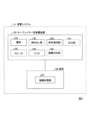
- FIG. 1 is a diagram showing an example of the functional configuration of an audio system using an open-ear type audio device.
- FIG. 2 is a diagram showing a second example of the open-ear type acoustic device of the first embodiment.
- FIG. 13 is a diagram showing a third example of the open-ear type acoustic device according to the first embodiment.
- FIG. 13 is a front view of a microphone 140 placed near the ear canal.
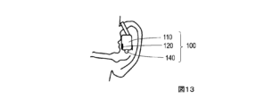
- FIG. 13 is a front view of a microphone 140 arranged on a side surface of a housing 110 (side surface of the housing).
- 1 is a front view of a microphone 140 disposed on the rear surface of the housing 110 (rear surface of the housing).
- 11 is a diagram showing the noise suppression performance of noise picked up by the microphone 140 when feedback active noise canceling (ANC) using acoustic information picked up by the microphone 140 is applied.
- ANC feedback active noise canceling
- FIG. 13 is a diagram showing the noise suppression performance of noise picked up by a dummy head in-ear microphone when feedback active noise canceling (ANC) is applied using acoustic information picked up by the microphone 140.
- FIG. 13 is a diagram showing the sound reproduced by the secondary sound source and picked up by the microphone 140.
- 11 is a diagram showing a correlation coefficient between a sound picked up by the microphone 140 and a sound picked up by a dummy head in-ear microphone.
- 1 is a diagram showing a sound reproduced by a primary sound source and picked up by a microphone 140.
- 11 is a diagram showing a correlation coefficient between a sound picked up by the microphone 140 and a sound picked up by a dummy head in-ear microphone.
- FIG. 1 shows a first example of an open-ear type acoustic device of the first embodiment.
- the open-ear type acoustic device shown in FIG. 1 is an earphone type.
- FIG. 2 shows an example of the functional configuration of an acoustic system using an open-ear type acoustic device.
- the open-ear type acoustic device 100 includes a housing 110, a speaker 120, a protruding portion 130, a microphone 140, and a signal processing portion 150.
- the open-ear type acoustic device 100 may also include a contact discrimination portion 160 and an output portion 170.
- the acoustic system 10 includes the open-ear type acoustic device 100 and a terminal 200 connected to the open-ear type acoustic device 100.
- the terminal 200 includes an information processing portion 210 that performs predetermined information processing using acoustic information collected by the microphone 140.
- the terminal 200 may be incorporated inside the open-ear type acoustic device 100, or may exist on a server such as a cloud.
- Figure 3 shows a second example of an open-ear type acoustic device of Example 1.
- the open-ear type acoustic device shown in Figure 3 is a headphone type.
- Figure 4 shows a third example of an open-ear type acoustic device of Example 1.
- the open-ear type acoustic device shown in Figure 4 is a type attached to an eyeglass frame.
- the types shown in Figures 1, 3, and 4 are representative of open-ear type acoustic devices 100, but there is no need to be limited to these.
- the open-ear type acoustic device 100 may be of an open type, and may have a structure in which there are no parts that come into contact with the concha cavity 910 and the ear canal 920.
- the housing 110 is an open-ear type. Open-ear type refers to a structure that keeps the ear canal open to the outside world.
- the housing 110 also has holding means 191, 192, 193 for positioning the open-ear type acoustic device 100 near the ear. In the example of FIG. 1, it is held to the ear by holding means 191. In the example of FIG. 2, it is held to the head by holding means 192. In the example of FIG. 3, it is held to the head together with the frame of glasses by holding means 193.
- the speaker 120 is disposed in the housing 110. In other words, the speaker 120 is disposed in a position that keeps the ear canal open to the outside world.
- the protruding portion 130 is held in the housing 110 so as to be positioned in the hollow space of the concha 910 or the ear canal 920. It is desirable that the position of the protruding portion 130 is adjustable. It is desirable that the protruding portion 130 is stretchable and bendable so that its position can be set. It is also desirable that the structure be such that the set position can be maintained.
- the microphone 140 picks up sound at the position where the protruding portion 130 is located.
- the microphone 140 may be located at the tip of the protruding portion 130 as shown in Figures 1, 3, and 4.
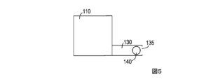
- the microphone 140 may be located in a space connected to a sound hole 135 formed in the protruding portion 130 as shown in Figures 5 to 7.
- Figure 5 is a diagram showing an image of a structure in which a sound hole is provided at the tip of the protruding portion and a microphone is located within the protruding portion.
- Figure 6 is a diagram showing an image of a structure in which a sound hole is provided midway through the protruding portion and a microphone is located within the protruding portion.
- Figure 7 is a diagram showing an image of a structure in which a sound hole is provided at the tip of the protruding portion and a microphone is located within the housing.
- the signal processing unit 150 generates a signal to be output from the speaker 120 based on the acoustic information collected by the microphone 140. For example, when the acoustic signal to be played on the terminal 200 is played on the speaker 120, the signal processing unit 150 may generate a signal that erases external sounds based on the acoustic information collected by the microphone 140. Alternatively, the signal processing unit 150 may generate a signal that emphasizes external sounds so that they are easier to hear based on the acoustic information collected by the microphone 140.
- the contact discrimination unit 160 determines that the protruding portion 130 or the microphone 140 is not in contact with the ear.
- the contact discrimination unit 160 may be a contact sensor arranged on the surface of the protruding portion 130 or the microphone 140.
- the contact discrimination unit 160 may determine that there is no contact by analyzing the acoustic information picked up by the microphone 140. This is because, when there is contact, it is considered that the acoustic information contains sounds caused by vibrations of the human body, or that the acoustic information contains sounds of specific frequencies attenuated by the human body. Providing the contact discrimination unit 160 makes it possible to prevent the open-ear acoustic device 100 from being used in an unexpected setting.
- the output unit 170 outputs a signal that prompts the user to adjust the position of the protruding portion 130 when the contact determination unit 160 determines that the protruding portion 130 or the microphone 140 is in contact with the ear.
- the signal that prompts the user to adjust the position of the protruding portion 130 may be a signal that is output from the speaker 120, or may be a signal to be displayed on the terminal 200 if the terminal 200 has a display function. Providing the output unit 170 makes it easier to inform the user that the protruding portion 130 needs to be adjusted.
- the information processing unit 210 is connected to the open-ear acoustic device 100 and performs predetermined information processing using the acoustic information picked up by the microphone 140.
- the information processing unit 210 may perform binaural recording processing, may perform processing associated with measuring the user's headphone transfer function (HpTF: Headphone Transfer Function), or may perform processing associated with measuring the user's head-related transfer function (HRTF: Head Related Transfer Function).
- HpTF Headphone Transfer Function
- HRTF Head Related Transfer Function
- the open-ear acoustic device 100 has an open-ear housing 110 and no parts that come into contact with the concha or ear canal, so it is less likely to cause a feeling of pressure or pain, and it reduces hygiene and other risks.
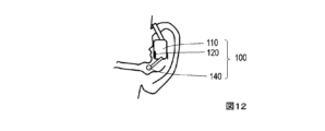
- FIG. 12 is a view from the front of the microphone 140 placed near the external ear canal.
- FIG. 13 is a view from the front of the microphone 140 placed on the side (side of the housing) of the housing 110.
- FIG. 14 is a view from the front of the microphone 140 placed on the rear (rear of the housing) of the housing 110.
- the primary sound source was aircraft cabin noise, reproduced by a speaker placed 0.8 m in front of the dummy head.
- the secondary sound source was the speaker 120 of the open-ear acoustic device 100 shown in Figures 8 to 14.
- FIG. 15 and FIG. 16 show the experimental results of feedback active noise canceling (ANC) processing. Both figures show the noise suppression performance of noise X(f) ANC-On when feedback active noise canceling is applied to noise reproduced by a primary sound source, with respect to noise X(f) ANC-Off when feedback active noise canceling is not applied.
- FIG. 15 shows the noise suppression performance of noise collected by the microphone 140 when feedback active noise canceling (ANC) is applied using acoustic information collected by the microphone 140.
- FIG. 16 shows the noise suppression performance of noise collected by a dummy head in-ear microphone when feedback active noise canceling (ANC) is applied using acoustic information collected by the microphone 140.
- the horizontal axis is frequency
- the vertical axis is the noise level. From FIG.
- noise can be suppressed at the position of the microphone 140 if it is placed other than on the back of the housing.
- Figures 17 to 19 show the experimental results of measuring the headphone transfer function (HpTF). This experiment is about the transfer function from the secondary sound source (speaker 120) to the dummy head in-ear microphone.
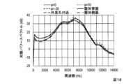
- Figure 17 shows the sound picked up by the microphone 140 when a TSP (Time Stretched Pulse) signal is played by the secondary sound source.
- Figure 18 shows the sound picked up by the dummy head in-ear microphone when a TSP signal is played by the secondary sound source.
- the horizontal axis is frequency
- the vertical axis is logarithmic power spectrum.
- the experimental results shown in Figure 18 show subtle differences even though the same sound is played by the secondary sound source and picked up by the same dummy head in-ear microphone.
- FIG. 19 is a diagram showing the correlation coefficient between the sound collected by the microphone 140 (sound shown in FIG. 17) and the sound collected by the dummy head in-ear microphone (sound shown in FIG. 18).
- the correlation coefficient was obtained from a spectrum of 0 to 14000 Hz.
- the microphone 140 When the microphone 140 is placed near the external ear canal, it can be seen that there is a sufficiently high correlation. From this result, it can be seen that if the microphone 140 is placed near the external ear canal or placed in the hollow of the space of the concha by appropriately selecting a position, it is possible to measure the headphone transfer function (HpTF) of the user using the microphone 140 of the open-ear type acoustic device 100.
- HpTF headphone transfer function
- the information processing portion 210 can perform processing for measuring the headphone transfer function of the user.
- FIG. 20 to 22 show experimental results of head-related transfer function (HRTF) measurement.
- HRTF head-related transfer function
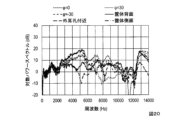
- FIG. 20 shows a sound reproduced by the primary sound source and picked up by the microphone 140.
- FIG. 21 shows a sound reproduced by the primary sound source and picked up by the dummy head ear microphone.
- the horizontal axis is frequency, and the vertical axis is logarithmic power spectrum.
- the experimental results shown in FIG. 21 show subtle differences even though the same sound is reproduced by the primary sound source and picked up by the same dummy head ear microphone.
- FIG. 22 shows the correlation coefficient between the sound picked up by the microphone 140 (sound shown in FIG. 20) and the sound picked up by the dummy head ear microphone (sound shown in FIG. 21).
- the correlation coefficient was obtained from the spectrum of 0 to 14000 Hz. It can be seen that there is a sufficiently high correlation when the microphone 140 is placed near the ear canal. From this result, it can be seen that if the microphone 140 is placed near the ear canal, it is possible to measure the user's head-related transfer function (HRTF) using the microphone 140 of the open-ear type acoustic device 100.
- HRTF head-related transfer function
- the open-ear acoustic device 100 of Example 1 also includes a speaker 120 and a signal processing unit 150. However, if the only purpose is to measure the user's head-related transfer function (HRTF) using the information processing unit 210, the speaker 120 and the signal processing unit 150 are not necessary. Therefore, the open-ear acoustic device of Modification 1 includes a housing 110, a protruding portion 130, and a microphone 140. Furthermore, the open-ear acoustic device 100 of Modification 1 only needs to be connected to a terminal 200 that includes the information processing unit 210. The housing 110, protruding portion 130, and microphone 140 are the same as those of Example 1.
- HRTF head-related transfer function
- the housing is also open-ear type and there are no parts that come into contact with the concha or ear canal, so there is less pressure and pain, and hygiene risks can be reduced.
Landscapes
- Physics & Mathematics (AREA)
- Engineering & Computer Science (AREA)
- Acoustics & Sound (AREA)
- Signal Processing (AREA)
- Multimedia (AREA)
- Headphones And Earphones (AREA)
Abstract
本発明の第1のオープンイヤー型音響装置は、筐体、スピーカ、突き出し部、マイク、信号処理部を備える。本発明の第2のオープンイヤー型音響装置は、筐体、突き出し部、マイクを備える。筐体は、オープンイヤー型である。スピーカは、筐体に配置される。突き出し部は、耳甲介腔もしくは外耳道の空間の中空に配置されるように筐体に保持される。マイクは、突き出し部が配置された位置の音を取得する。信号処理部は、マイクで収音された音響情報に基づいてスピーカから出力する信号を生成する。
Description
本発明は、オープンイヤー型の筐体を有する音響装置であるオープンイヤー型音響装置および、オープンイヤー型音響装置を用いた音響システム関する。
ノイズキャンセリングなどの信号処理を行うウェアラブルな音響装置(イヤホン、ヘッドホンなど)として、非特許文献1に示すようなヘッドホンなどが知られている。このような音響装置は密閉型が多く、密閉型ヘッドホン、カナル型イヤホンとして知られている。密閉型の音響装置の場合、耳穴を外界に開放していない。
SONY,ヘッドホン"ワイヤレスノイズキャンセリングステレオヘッドセットWH-1000XM4",[令和5年5月23日検索]、インターネット<https://www.sony.jp/headphone/products/WH-1000XM4/feature_1.html>.
しかしながら、従来技術は、外界から遮断されること、耳に接する部分があることなどから、耳への圧迫感、痛みなどがあり、衛生面でのリスクおよび外耳炎などの病気のリスクがあるという課題がある。また、仮に開放型(オープンイヤー型)であったとしても、耳甲介腔もしくは外耳道などに何らかの部品が接する場合は、圧迫感および痛みが伴う可能性があり、衛生面でのリスクおよび外耳炎などの病気のリスクが高くなるという課題がある。
本発明はこのような問題に鑑みてなされたものであり、圧迫感および痛みが伴いにくく、衛生面などでのリスクを軽減できるウェアラブルな音響装置を提供することを目的とする。
本発明はこのような問題に鑑みてなされたものであり、圧迫感および痛みが伴いにくく、衛生面などでのリスクを軽減できるウェアラブルな音響装置を提供することを目的とする。
本発明の第1のオープンイヤー型音響装置は、筐体、スピーカ、突き出し部、マイク、信号処理部を備える。本発明の第2のオープンイヤー型音響装置は、筐体、突き出し部、マイクを備える。筐体は、オープンイヤー型である。スピーカは、筐体に配置される。突き出し部は、耳甲介腔もしくは外耳道の空間の中空に配置されるように筐体に保持される。マイクは、突き出し部が配置された位置の音を取得する。信号処理部は、マイクで収音された音響情報に基づいてスピーカから出力する信号を生成する。
本発明のオープンイヤー型音響装置によれば、筐体がオープンイヤー型であり、耳甲介腔および外耳道に接する部品がないので、圧迫感および痛みが伴いにくく、衛生面などでのリスクを軽減できる。
以下、本発明の実施の形態について、詳細に説明する。なお、同じ機能を有する構成部には同じ番号を付し、重複説明を省略する。
図1に実施例1のオープンイヤー型音響装置の第1例を示す。図1に示されたオープンイヤー型音響装置は、イヤホンタイプである。図2にオープンイヤー型音響装置を用いた音響システムの機能構成例を示す。オープンイヤー型音響装置100は、筐体110、スピーカ120、突き出し部130、マイク140、信号処理部150を備える。オープンイヤー型音響装置100は、接触判別部160、出力部170も備えてもよい。音響システム10は、オープンイヤー型音響装置100とオープンイヤー型音響装置100に接続された端末200で構成される。端末200は、マイク140で収音された音響情報を用いてあらかじめ定めた情報処理を行う情報処理部210を備える。ただし、端末200は、オープンイヤー型音響装置100の内部に組み込まれていてもよいし、クラウドなどのサーバ上に存在してもよい。
図3に実施例1のオープンイヤー型音響装置の第2例を示す。図3に示されたオープンイヤー型音響装置は、ヘッドホンタイプである。図4に実施例1のオープンイヤー型音響装置の第3例を示す。図4に示されたオープンイヤー型音響装置は、眼鏡のフレーム装着タイプである。オープンイヤー型音響装置100としては、図1,3,4に示したタイプが代表的であるが、これらに限定する必要はない。オープンイヤー型音響装置100は、開放型であって、耳甲介腔910および外耳道920に接触する部品がないような構造であればよい。
筐体110は、オープンイヤー型である。オープンイヤー型とは、耳穴が外界に開放された状態を維持する構造であることを意味している。筐体110は、オープンイヤー型音響装置100を耳近傍に配置するための保持手段191,192,193も有している。図1の例では保持手段191によって耳に保持される。図2の例では、保持手段192によって頭部に保持される。図3の例では、保持手段193によって、眼鏡のフレームと共に頭部に保持される。スピーカ120は、筐体110に配置される。つまり、スピーカ120は、耳穴が外界に解放された状態を維持する位置に配置されている。
突き出し部130は、耳甲介腔910もしくは外耳道920の空間の中空に配置されるように筐体110に保持される。突き出し部130の位置は調整可能であることが望ましい。突き出し部130は、伸縮でき、曲げることができることで位置を設定できることが望ましい。また、設定した位置を維持できる構造であることが望ましい。
マイク140は、突き出し部130が配置された位置の音を取得する。例えば、マイク140は、図1,3,4に示されているように突き出し部130の先端に配置されてもよい。もしくは、マイク140は、図5~7に示しているように、突き出し部130に形成された音孔135から繋がっている空間に配置してもよい。図5は突き出し部の先端に音孔を設け、突き出し部内にマイクを配置した構造のイメージを示す図である。図6は突き出し部の途中に音孔を設け、突き出し部内にマイクを配置した構造のイメージを示す図である。図7は突き出し部の先端に音孔を設け、筐体内にマイクを配置した構造のイメージを示す図である。
信号処理部150は、マイク140で収音された音響情報に基づいてスピーカ120から出力する信号を生成する。例えば、信号処理部150は、端末200で再生する音響信号をスピーカ120で再生する際に、マイク140で収音された音響情報に基づいて外界の音を消去する信号を生成してもよい。または、信号処理部150は、マイク140で収音された音響情報に基づいて外界の音が聞こえやすくなるように強調した信号を生成してもよい。
接触判別部160は、突き出し部130もしくはマイク140が耳に接触していないことを判別する。例えば、接触判別部160は、突き出し部130もしくはマイク140の表面に配置された接触センサとしてもよい。もしくは、接触判別部160は、マイク140で収音した音響情報を分析することで接触していないことを判別してもよい。接触した場合には、人体の振動に起因した音が音響情報に含まれていること、もしくは人体によって特定の周波数の音が減衰した音響情報が含まれていることが考えられるからである。接触判別部160を備えることで、想定していない設定でオープンイヤー型音響装置100が使用されることを防ぐことができる。
出力部170は、接触判別部160が、突き出し部130もしくはマイク140が耳に接触していると判別したときに、突き出し部130の位置を調整することを促す信号を出力する。調整することを促す信号は、スピーカ120から出力する信号でもよいし、端末200が表示機能を有している場合は端末200に表示するための信号でもよい。出力部170を備えることで、利用者に突き出し部130の調整が必要であることを知らせやすくなる。
情報処理部210は、オープンイヤー型音響装置100に接続され、マイク140で収音された音響情報を用いてあらかじめ定めた情報処理を行う。例えば、情報処理部210は、バイノーラル録音の処理を行ってもよいし、利用者のヘッドホン伝達関数(HpTF:Headphone Transfer Function)測定に伴う処理を行ってもよいし、利用者の頭部伝達関数(HRTF:Head Related Transfer Function)測定に伴う処理を行ってもよい。なお、ヘッドホン伝達関数(HpTF:Headphone Transfer Function)とは、ヘッドホンの入力から耳(鼓膜もしくは外耳道入口)までの伝達関数を意味している。
オープンイヤー型音響装置100によれば、筐体110がオープンイヤー型であり、耳甲介腔および外耳道に接する部品がないので、圧迫感および痛みが伴いにくく、衛生面などでのリスクを軽減できる。
<実験>
図1に示したタイプのオープンイヤー型音響装置100とダミーヘッドを用いて、フィードバック型アクティブノイズキャンセリング(ANC:Active Noise Cancelling)処理、ヘッドホン伝達関数(HpTF:Headphone Transfer Function)測定、頭部伝達関数(HRTF:Head Related Transfer Function)測定の実験を行った。これらの実験では、マイク140を次に説明する6種類の位置に配置した。図8は左耳の耳甲介腔の空間の中空に、マイク140を右耳側(φ=0)に配置した様子を、正面から見た図である。図9は左耳の耳甲介腔の空間の中空に、マイク140を右耳側(φ=0)に配置した様子を、左側面から見た図である。図10は左耳の耳甲介腔の空間の中空に、マイク140を右耳側よりも30度前方(φ=30)に配置した様子を、左側面から見た図である。図11は左耳の耳甲介腔の空間の中空に、マイク140を右耳側よりも30度後方(φ=-30)に配置した様子を、左側面から見た図である。φ=30,φ=-30の場合の正面から見た図は省略するが、正面から見たマイク140の位置は、図8よりは少し右側になる。図8~11で説明しているマイク140は、右耳側と左耳側の軸と、前方と後方の軸で形成される平面内に配置されており、右耳側がφ=0,前方はφが正の方向、後方はφが負の方向である。図12は、マイク140を外耳孔付近に配置した様子を、正面から見た図である。図13は、マイク140を筐体110の側面(筐体側面)に配置した様子を、正面から見た図である。図14は、マイク140を筐体110の背面(筐体背面)に配置した様子を、正面から見た図である。左耳の耳甲介腔の空間の中空にマイク140を配置する種類は、φ=0,φ=30,φ=-30の3種類である(図8~11参照)。その他に、外耳孔付近に配置、筐体側面に配置、筐体背面に配置の3種類であり(図12~14参照)、合計6種類で実験を行った。
図1に示したタイプのオープンイヤー型音響装置100とダミーヘッドを用いて、フィードバック型アクティブノイズキャンセリング(ANC:Active Noise Cancelling)処理、ヘッドホン伝達関数(HpTF:Headphone Transfer Function)測定、頭部伝達関数(HRTF:Head Related Transfer Function)測定の実験を行った。これらの実験では、マイク140を次に説明する6種類の位置に配置した。図8は左耳の耳甲介腔の空間の中空に、マイク140を右耳側(φ=0)に配置した様子を、正面から見た図である。図9は左耳の耳甲介腔の空間の中空に、マイク140を右耳側(φ=0)に配置した様子を、左側面から見た図である。図10は左耳の耳甲介腔の空間の中空に、マイク140を右耳側よりも30度前方(φ=30)に配置した様子を、左側面から見た図である。図11は左耳の耳甲介腔の空間の中空に、マイク140を右耳側よりも30度後方(φ=-30)に配置した様子を、左側面から見た図である。φ=30,φ=-30の場合の正面から見た図は省略するが、正面から見たマイク140の位置は、図8よりは少し右側になる。図8~11で説明しているマイク140は、右耳側と左耳側の軸と、前方と後方の軸で形成される平面内に配置されており、右耳側がφ=0,前方はφが正の方向、後方はφが負の方向である。図12は、マイク140を外耳孔付近に配置した様子を、正面から見た図である。図13は、マイク140を筐体110の側面(筐体側面)に配置した様子を、正面から見た図である。図14は、マイク140を筐体110の背面(筐体背面)に配置した様子を、正面から見た図である。左耳の耳甲介腔の空間の中空にマイク140を配置する種類は、φ=0,φ=30,φ=-30の3種類である(図8~11参照)。その他に、外耳孔付近に配置、筐体側面に配置、筐体背面に配置の3種類であり(図12~14参照)、合計6種類で実験を行った。
1次音源として、飛行機内騒音をダミーヘッドの正面0.8mの位置に配置したスピーカで再生した。2次音源は、図8~14に示したオープンイヤー型音響装置100のスピーカ120である。
図15と図16にフィードバック型アクティブノイズキャンセリング(ANC)処理の実験結果を示す。いずれの図も、1次音源で再生した騒音について、フィードバック型アクティブノイズキャンセリング未適用時の騒音X(f)ANC-Offに対するフィードバック型アクティブノイズキャンセリング適用時の騒音X(f)ANC-Onの雑音抑圧性能を示している。図15は、マイク140で収音した音響情報を用いたフィードバック型アクティブノイズキャンセリング(ANC)適用時の、マイク140で収音した騒音の雑音抑圧性能を示している。図16は、マイク140で収音した音響情報を用いたフィードバック型アクティブノイズキャンセリング(ANC)適用時の、ダミーヘッド耳内マイクで収音した騒音の雑音抑圧性能を示している。横軸は周波数、縦軸は騒音の大きさである。図15からは、筐体背面以外の配置であれば、マイク140の位置では騒音を抑圧できていることが分かる。図16からは、マイク140を外耳孔付近に配置したときには200~400Hzで雑音抑圧特性が特によく、全体的にも騒音を抑圧できていることが分かる。また、耳甲介腔の空間の中空にマイク140を配置した場合は、φ=0,φ=30,φ=-30のいずれの場合も200~600Hzで10dB以上騒音を抑圧していることが分かる。また、筐体側面および筐体背面にマイク140を配置しても十分な雑音抑圧特性が得られないことも分かる。
図17~19にヘッドホン伝達関数(HpTF)測定の実験結果を示す。この実験では、2次音源(スピーカ120)からダミーヘッド耳内マイクまでの伝達関数に関する実験である。図17は2次音源でTSP(Time Stretched Pulse)信号を再生し、マイク140で収音した音を示す図である。図18は2次音源でTSP信号を再生し、ダミーヘッド耳内マイクで収音した音を示す図である。横軸は周波数、縦軸は対数パワースペクトルである。図18に示す実験結果は、同じ音を2次音源で再生し、同じダミーヘッド耳内マイクで収音しているにも関わらず微妙な相違があるのは、マイク140の位置の種類によって、オープンイヤー型音響装置100の取付位置に違いがあること、マイク140の位置に違いがあることなどに起因すると考えられる。図19は、マイク140で収音した音(図17に示した音)とダミーヘッド耳内マイクで収音した音(図18に示した音)との相関係数を示す図である。相関係数は、0~14000Hzのスペクトルから求めた。耳甲介腔の空間の中空にマイク140を配置した場合は、φ=0,φ=-30では高い相関関係があることが分かる。一方、φ=30では相関係数が小さい。外耳孔付近にマイク140を配置した場合は、十分高い相関関係があることが分かる。この結果から、外耳孔付近にマイク140を配置する、もしくは位置を適宜選択して耳甲介腔の空間の中空にマイク140を配置すれば、オープンイヤー型音響装置100のマイク140を用いて利用者のヘッドホン伝達関数(HpTF)測定ができる可能性があることが分かる。つまり、突き出し部130を、耳甲介腔の空間のあらかじめ定めた中空もしくは外耳道の空間の中空に配置されるように筐体110に保持させれば、情報処理部210は利用者のヘッドホン伝達関数測定のための処理を行うことができる。
図20~22に頭部伝達関数(HRTF)測定の実験結果を示す。この実験では、1次音源(ダミーヘッドの正面0.8mの位置に配置したスピーカ)からダミーヘッド耳内マイクまでの伝達関数に関する実験である。図20は1次音源で再生し、マイク140で収音した音を示す図である。図21は1次音源で再生し、ダミーヘッド耳内マイクで収音した音を示す図である。横軸は周波数、縦軸は対数パワースペクトルである。図21に示す実験結果は、同じ音を1次音源で再生し、同じダミーヘッド耳内マイクで収音しているにも関わらず微妙な相違があるのは、マイク140の位置の種類によって、オープンイヤー型音響装置100の取付位置に違いがあること、マイク140の位置に違いがあることなどに起因すると考えられる。図22は、マイク140で収音した音(図20に示した音)とダミーヘッド耳内マイクで収音した音(図21に示した音)との相関係数を示す図である。相関係数は、0~14000Hzのスペクトルから求めた。外耳孔付近にマイク140を配置した場合は、十分高い相関関係があることが分かる。この結果から、外耳孔付近にマイク140を配置すれば、オープンイヤー型音響装置100のマイク140を用いて利用者の頭部伝達関数(HRTF)測定ができる可能性があることが分かる。また、利用者の頭部伝達関数(HRTF)がかかった音源の録音(バイノーラル録音)が可能であるといえる。つまり、突き出し部130を、外耳道の空間の中空に配置されるように筐体110に保持させれば、情報処理部210は利用者の頭部伝達関数測定のための処理を行うことができる。また、情報処理部210は、測定した頭部伝達関数がかかった音源の録音を行うことができる。
[変形例1]
[変形例1]
実施例1のオープンイヤー型音響装置100は、スピーカ120と信号処理部150も備えていた。しかし、情報処理部210を用いて利用者の頭部伝達関数(HRTF:Head Related Transfer Function)測定を行うだけであれば、スピーカ120と信号処理部150は不要である。したがって、変形例1のオープンイヤー型音響装置は、筐体110、突き出し部130、マイク140を備える。また、変形例1のオープンイヤー型音響装置100は、情報処理部210を備えた端末200と接続すればよい。筐体110、突き出し部130、マイク140は、実施例1と同じである。
変形例のオープンイヤー型音響装置の場合も、筐体がオープンイヤー型であり、耳甲介腔および外耳道に接する部品がないので、圧迫感および痛みが伴いにくく、衛生面などでのリスクを軽減できる。
10 音響システム 100 オープンイヤー型音響装置
110 筐体 120 スピーカ
130 突き出し部 135 音孔
140 マイク 150 信号処理部
160 接触判別部 170 出力部
191,192,193 保持手段 200 端末
210 情報処理部
110 筐体 120 スピーカ
130 突き出し部 135 音孔
140 マイク 150 信号処理部
160 接触判別部 170 出力部
191,192,193 保持手段 200 端末
210 情報処理部
Claims (7)
- オープンイヤー型の筐体と、
前記筐体に配置されたスピーカと、
耳甲介腔もしくは外耳道の空間の中空に配置されるように前記筐体に保持された突き出し部と、
前記突き出し部が配置された位置の音を取得するマイクと、
前記マイクで収音された音響情報に基づいて前記スピーカから出力する信号を生成する信号処理部と、
を備えるオープンイヤー型音響装置。 - 請求項1記載のオープンイヤー型音響装置であって、
前記突き出し部の位置は調整可能である
ことを特徴とするオープンイヤー型音響装置。 - 請求項2記載のオープンイヤー型音響装置であって、
前記突き出し部もしくは前記マイクが耳に接触していないことを判別する接触判別部
も有することを特徴とするオープンイヤー型音響装置。 - 請求項3記載のオープンイヤー型音響装置であって、
前記接触判別部が、前記突き出し部もしくは前記マイクが耳に接触していると判別したときに、前記突き出し部の位置を調整することを促す信号を出力する出力部
も有することを特徴とするオープンイヤー型音響装置。 - オープンイヤー型の筐体と、
耳甲介腔もしくは外耳道の空間の中空に配置されるように前記筐体に保持された突き出し部と、
前記突き出し部が配置された位置の音を取得するマイクと、
を備えるオープンイヤー型音響装置。 - 請求項1~4のいずれかに記載のオープンイヤー型音響装置と、
前記オープンイヤー型音響装置に接続され、前記マイクで収音された音響情報を用いてあらかじめ定めた情報処理を行う情報処理部を備える端末
を有し、
前記突き出し部は、耳甲介腔の空間のあらかじめ定めた中空もしくは外耳道の空間の中空に配置されるように前記筐体に保持されており、
前記情報処理部は、利用者のヘッドホン伝達関数測定のための処理を行う
ことを特徴とする音響システム。 - 請求項1~5のいずれかに記載のオープンイヤー型音響装置と、
前記オープンイヤー型音響装置に接続され、前記マイクで収音された音響情報を用いてあらかじめ定めた情報処理を行う情報処理部を備える端末
を有し、
前記突き出し部は、外耳道の空間の中空に配置されるように前記筐体に保持されており、
前記情報処理部は、利用者の頭部伝達関数測定のための処理、または前記頭部伝達関数がかかった音源の録音の処理を行う
ことを特徴とする音響システム。
Priority Applications (3)
| Application Number | Priority Date | Filing Date | Title |
|---|---|---|---|
| PCT/JP2023/021192 WO2024252569A1 (ja) | 2023-06-07 | 2023-06-07 | オープンイヤー型音響装置、音響システム |
| JP2025526026A JPWO2024252880A1 (ja) | 2023-06-07 | 2024-05-16 | |
| PCT/JP2024/018059 WO2024252880A1 (ja) | 2023-06-07 | 2024-05-16 | オープンイヤー型音響装置、音響システム |
Applications Claiming Priority (1)
| Application Number | Priority Date | Filing Date | Title |
|---|---|---|---|
| PCT/JP2023/021192 WO2024252569A1 (ja) | 2023-06-07 | 2023-06-07 | オープンイヤー型音響装置、音響システム |
Publications (1)
| Publication Number | Publication Date |
|---|---|
| WO2024252569A1 true WO2024252569A1 (ja) | 2024-12-12 |
Family
ID=93795393
Family Applications (2)
| Application Number | Title | Priority Date | Filing Date |
|---|---|---|---|
| PCT/JP2023/021192 Ceased WO2024252569A1 (ja) | 2023-06-07 | 2023-06-07 | オープンイヤー型音響装置、音響システム |
| PCT/JP2024/018059 Ceased WO2024252880A1 (ja) | 2023-06-07 | 2024-05-16 | オープンイヤー型音響装置、音響システム |
Family Applications After (1)
| Application Number | Title | Priority Date | Filing Date |
|---|---|---|---|
| PCT/JP2024/018059 Ceased WO2024252880A1 (ja) | 2023-06-07 | 2024-05-16 | オープンイヤー型音響装置、音響システム |
Country Status (2)
| Country | Link |
|---|---|
| JP (1) | JPWO2024252880A1 (ja) |
| WO (2) | WO2024252569A1 (ja) |
Citations (2)
| Publication number | Priority date | Publication date | Assignee | Title |
|---|---|---|---|---|
| JP2000092589A (ja) * | 1998-09-16 | 2000-03-31 | Oki Electric Ind Co Ltd | イヤホン及び頭外音像定位装置 |
| JP3240241U (ja) * | 2021-10-21 | 2022-12-15 | 深▲せん▼市大十未来科技有限公司 | 開放式耳掛け型ウェアラブル発音装置 |
Family Cites Families (2)
| Publication number | Priority date | Publication date | Assignee | Title |
|---|---|---|---|---|
| JP6922603B2 (ja) * | 2017-09-26 | 2021-08-18 | 株式会社Jvcケンウッド | 信号処理装置、信号処理方法、及びプログラム |
| WO2023095757A1 (ja) * | 2021-11-26 | 2023-06-01 | クレプシードラ株式会社 | 音響装置 |
-
2023
- 2023-06-07 WO PCT/JP2023/021192 patent/WO2024252569A1/ja not_active Ceased
-
2024
- 2024-05-16 JP JP2025526026A patent/JPWO2024252880A1/ja active Pending
- 2024-05-16 WO PCT/JP2024/018059 patent/WO2024252880A1/ja not_active Ceased
Patent Citations (2)
| Publication number | Priority date | Publication date | Assignee | Title |
|---|---|---|---|---|
| JP2000092589A (ja) * | 1998-09-16 | 2000-03-31 | Oki Electric Ind Co Ltd | イヤホン及び頭外音像定位装置 |
| JP3240241U (ja) * | 2021-10-21 | 2022-12-15 | 深▲せん▼市大十未来科技有限公司 | 開放式耳掛け型ウェアラブル発音装置 |
Also Published As
| Publication number | Publication date |
|---|---|
| WO2024252880A1 (ja) | 2024-12-12 |
| JPWO2024252880A1 (ja) | 2024-12-12 |
Similar Documents
| Publication | Publication Date | Title |
|---|---|---|
| US9949048B2 (en) | Controlling own-voice experience of talker with occluded ear | |
| EP2202998B1 (en) | A device for and a method of processing audio data | |
| CN101091412B (zh) | 用于声音增强的装置和方法 | |
| US9615189B2 (en) | Artificial ear apparatus and associated methods for generating a head related audio transfer function | |
| US8682010B2 (en) | Automatic environmental acoustics identification | |
| CN109565626B (zh) | 具有主动降噪功能的声学开放式耳机 | |
| US20130094657A1 (en) | Method and device for improving the audibility, localization and intelligibility of sounds, and comfort of communication devices worn on or in the ear | |
| Denk et al. | Acoustic transparency in hearables—technical evaluation | |
| JP7047773B2 (ja) | 収音装置 | |
| EP2830324B1 (en) | Headphone and headset | |
| US10748522B2 (en) | In-ear microphone with active noise control | |
| JP7672740B2 (ja) | 音響装置 | |
| JP6668766B2 (ja) | 音声信号処理装置 | |
| WO2024252880A1 (ja) | オープンイヤー型音響装置、音響システム | |
| Brammer et al. | Understanding speech when wearing communication headsets and hearing protectors with subband processing | |
| Hoffmann et al. | Quantitative assessment of spatial sound distortion by the semi-ideal recording point of a hear-through device | |
| JPS59191996A (ja) | 聴音器 | |
| JP3374731B2 (ja) | バイノーラル再生装置、バイノーラル再生用ヘッドホンおよび音源評価方法 | |
| KR200426390Y1 (ko) | 마이크를 구비하는 이어폰 | |
| JP2020099094A (ja) | 信号処理装置 | |
| JP7052300B2 (ja) | 音響出力装置 | |
| RU222990U1 (ru) | Стереогарнитура с бинауральным звуком | |
| US12081944B1 (en) | Audio device apparatus for hearing impaired users | |
| Usagawa | In-ear microphone measures in the ear canal with bone conduction stimulation: An application for estimating a cross-talk compensation filter | |
| JP3319176B2 (ja) | 電子聴診器 |
Legal Events
| Date | Code | Title | Description |
|---|---|---|---|
| 121 | Ep: the epo has been informed by wipo that ep was designated in this application |
Ref document number: 23940671 Country of ref document: EP Kind code of ref document: A1 |
|
| NENP | Non-entry into the national phase |
Ref country code: DE |