WO2024252516A1 - 浄水器用治具 - Google Patents
浄水器用治具 Download PDFInfo
- Publication number
- WO2024252516A1 WO2024252516A1 PCT/JP2023/020981 JP2023020981W WO2024252516A1 WO 2024252516 A1 WO2024252516 A1 WO 2024252516A1 JP 2023020981 W JP2023020981 W JP 2023020981W WO 2024252516 A1 WO2024252516 A1 WO 2024252516A1
- Authority
- WO
- WIPO (PCT)
- Prior art keywords
- water purifier
- central axis
- circumferential direction
- jig
- dial
- Prior art date
- Legal status (The legal status is an assumption and is not a legal conclusion. Google has not performed a legal analysis and makes no representation as to the accuracy of the status listed.)
- Ceased
Links
Images




Classifications
-
- A—HUMAN NECESSITIES
- A47—FURNITURE; DOMESTIC ARTICLES OR APPLIANCES; COFFEE MILLS; SPICE MILLS; SUCTION CLEANERS IN GENERAL
- A47J—KITCHEN EQUIPMENT; COFFEE MILLS; SPICE MILLS; APPARATUS FOR MAKING BEVERAGES
- A47J31/00—Apparatus for making beverages
- A47J31/44—Parts or details or accessories of beverage-making apparatus
- A47J31/60—Cleaning devices
-
- B—PERFORMING OPERATIONS; TRANSPORTING
- B67—OPENING, CLOSING OR CLEANING BOTTLES, JARS OR SIMILAR CONTAINERS; LIQUID HANDLING
- B67B—APPLYING CLOSURE MEMBERS TO BOTTLES JARS, OR SIMILAR CONTAINERS; OPENING CLOSED CONTAINERS
- B67B7/00—Hand- or power-operated devices for opening closed containers
- B67B7/18—Hand- or power-operated devices for opening closed containers for removing threaded caps
-
- C—CHEMISTRY; METALLURGY
- C02—TREATMENT OF WATER, WASTE WATER, SEWAGE, OR SLUDGE
- C02F—TREATMENT OF WATER, WASTE WATER, SEWAGE, OR SLUDGE
- C02F1/00—Treatment of water, waste water, or sewage
-
- C—CHEMISTRY; METALLURGY
- C02—TREATMENT OF WATER, WASTE WATER, SEWAGE, OR SLUDGE
- C02F—TREATMENT OF WATER, WASTE WATER, SEWAGE, OR SLUDGE
- C02F1/00—Treatment of water, waste water, or sewage
- C02F1/28—Treatment of water, waste water, or sewage by sorption
Definitions
- This disclosure relates to a jig for a water purifier.
- Water purifiers that purify supplied water include, for example, a water purification filter that is connected to a water faucet, and a prefilter that is placed on the water supply side of the water purification filter.
- the water purification filter mainly removes, for example, dissolved components from the water.
- the prefilter mainly removes, for example, solid components from the water.
- Patent Document 1 discloses a prefilter for a water purifier that uses a switching mechanism to selectively switch between multiple modes with different paths from the water inlet to the water outlet.
- the switching mechanism is, for example, a dial that can be rotated relative to the water purifier body.
- the filter is housed, for example, in a cylindrical housing.
- the housing is fixed to the valve seat, for example, by screwing a male threaded portion formed on the housing into a female threaded portion formed on the valve seat.
- the housing is rotated to remove it from the valve seat.
- a rotating water purifier jig is used when rotating the dial and when rotating the housing.
- the dial size differs depending on the model, it is necessary to prepare a jig according to the size of the dial. For example, if a jig is used that has an attachment part for the dial on one longitudinal side and an attachment part for the housing on the other longitudinal side, it is necessary to change the orientation of the handle, which reduces workability.
- This disclosure was made in consideration of the above points, and aims to provide a tool for a water purifier that can accommodate dials of different sizes and has good workability.
- the first aspect of the present disclosure is a jig for a water purifier that rotates a rotating member in a water purifier, the jig having a pair of gripping parts that extend along a line segment that extends in a radial direction about a central axis and are arranged on both sides of the line segment in the circumferential direction about the central axis, and a curved part that extends in a curved manner in the circumferential direction and connects the inner ends of the pair of gripping parts in the radial direction, the curved part having an inner circumferential surface located on the inside in the radial direction, a gripping part that elastically deforms according to the size of the gap between the pair of gripping parts and whose distance in the direction perpendicular to the central axis and the line segment changes, and a plurality of engaging parts that are provided at intervals in the circumferential direction, are formed of grooves recessed from the inner ends in the radial direction to the outside in the radial direction,
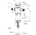
- FIG. 2 is an exploded perspective view of the water purifier jig and the water purifier according to the present disclosure.
- FIG. 2 is a perspective view of the water purifier without a cover member.
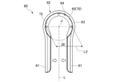
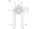
- FIG. 2 is a perspective view of the water purifier jig as viewed from below. This is a diagram showing the water purifier jig attached to the dial.
- FIG. 13 is a vertical cross-sectional view showing a water purifier jig attached to a dial. This is a diagram showing the water purifier jig attached to the dial.
- FIG. 13 is a diagram showing the water purifier jig attached to the housing.
- the water purifier jig 60 is used to rotate the dial 30 and the housing 13A of the water purifier 1 in the circumferential direction around the central axis J.
- the dial 30 and the housing 13A are the rotating members R.
- the water purifier 1 includes a water purifier main body 10 and a dial 30.
- the water purifier body 10 is cylindrical and extends vertically around a central axis J.
- the water purifier body 10 includes a valve seat 11, a valve body 12, a filter element 13, a first cover member 14, a second cover member 15, a third cover member 16, a switching member 17, and a drain handle 18.
- the valve seat 11 is formed of a metal material, for example.
- the valve seat 11 has a water inlet section 21 and a water outlet section 22.
- a water supply pipe is connected to the water inlet section 21, and for example, clean water enters.
- a water outlet pipe is connected to the water outlet section 22.
- the water outlet section 22 allows the water that has passed through the filter element 13 to exit, for example.
- the direction in which the water inlet section 21 and the water outlet section 22 are arranged with respect to the central axis J is referred to as the left-right direction
- the side in which the water inlet section 21 is arranged is referred to as the left side
- the side in which the water outlet section 22 is arranged is referred to as the right side.
- the direction perpendicular to the left-right direction and the up-down direction is referred to as the facing direction in which the worker faces.
- the facing direction when the water flow at the installation location is from left to right, the side facing the worker is referred to as the front side, and when the water flow is from right to left, the side facing the worker is referred to as the back side.
- the valve body 12 is formed of a resin material, for example.
- the valve body 12 is fitted liquid-tightly into the valve seat 11 so as to be rotatable in the circumferential direction about the central axis J.
- the switching member 17 is formed of a resin material, for example.
- the switching member 17 is attached to the upper side of the valve body 12.
- the switching member 17 is fixed to the valve body 12 in a state in which it is prevented from rotating.
- the switching member 17 rotates around the central axis J, the valve body 12 rotates in an integrated state.
- the filter element 13 is disposed below the valve seat 11 and the valve body 12.
- the filter element 13 has a housing 13A, a filter 13B, and a drainage section 13C.
- the housing 13A is made of a resin material.
- the housing 13A is formed in a cylindrical shape that extends in the vertical direction.
- the housing 13A is open at the upper end.
- the housing 13A has a male thread at the upper end, and is fixed to the valve seat 11 from below by being screwed into a female thread formed in the valve seat 11.
- the housing 13A has rib portions 13D that protrude radially outward from the outer circumferential surface.
- the rib portions 13D are disposed on the upper side of the housing 13A.
- a plurality of rib portions 13D are provided at intervals in the circumferential direction.
- Four rib portions 13D are provided at 90 degree intervals in the circumferential direction.
- Filter 13B mainly removes, for example, solid components from the water.
- Filter 13B extends vertically around central axis J.
- Filter 13B is disposed inside housing 13A and radially spaced from housing 13A.
- the lower end of filter 13B is connected to the lower end of housing 13A and drainage section 13C.
- the drainage section 13C is connected to the filter 13B from below.
- the drainage section 13C has a drainage channel that extends vertically around the central axis J.
- a drainage pipe can be connected to the lower end of the drainage section 13C. Water drained from the drainage channel is discharged via the drainage pipe.
- the drain handle 18 is positioned on the side facing the operator when the water flow at the installation location is from left to right.
- the drain handle 18 is circular when viewed from the front.
- the drain handle 18 can be rotated around an axis that extends in the facing direction. When rotated, the drain handle 18 can switch between opening and closing the drainage channel.
- the first cover member 14 is formed of a resin material, for example.
- the first cover member 14 is formed in a cylindrical shape that covers the upper side of the water purifier main body 10 from the radial outside.
- the first cover member 14 covers the periphery of the valve seat 11 and the valve body 12 from the radial outside while leaving the upper side of the switching member 17 exposed.
- the outer diameter of the first cover member 14 and the outer diameter of the dial 30 are the same.
- the water inlet section 21 and the water outlet section 22 are provided to protrude radially outward from the first cover member 14.
- the first cover member 14 has an indicator portion 14A located near the upper end on the outer circumferential surface. If the center position of the water inlet portion 21 in the circumferential direction is taken as 0 degrees, the indicator portion 14A is located at a position 90 degrees counterclockwise corresponding to one side in the circumferential direction when viewed from the front, and at a position 90 degrees clockwise corresponding to the other side in the circumferential direction. As an example, the indicator portion 14A is formed in a dot shape.
- the second cover member 15 is formed, for example, from a resin material.
- the second cover member 15 is formed in a cylindrical shape that covers the lower side of the first cover member 14 in the water purifier body 10 from the outside in the radial direction.
- the second cover member 15 covers the periphery of the filter element 13 from the outside in the radial direction.
- the outer diameter of the second cover member 15 is the same as the outer diameter of the first cover member 14.
- the third cover member 16 is formed, for example, from a resin material.
- the third cover member 16 is formed in a cylindrical shape that covers the lower side of the second cover member 15 in the water purifier body 10 from the outside in the radial direction.
- the third cover member 16 covers the periphery of the drainage section 13C from the outside in the radial direction.
- the outer diameter of the third cover member 16 and the outer diameter of the second cover member 15 are the same.
- the outer diameter of the dial 30, the outer diameter of the first cover member 14, the outer diameter of the second cover member 15, and the outer diameter of the third cover member 16 are the same.
- the dial 30 is provided on the water purifier body 10.
- the dial 30 is provided on the switching member 17.
- the dial 30 can rotate in a circumferential direction relative to the water purifier body 10.
- the dial 30 can select from a number of modes in which water introduced from the water inlet 21 is discharged through different routes depending on the circumferential position relative to the water purifier body 10.
- One of the multiple modes is a mode in which water is introduced through the water inlet 21, passes through the gap between the housing 13A and the filter 13B, and then follows a path that allows it to flow out of the water outlet 22 via the filter 13B.
- the other of the multiple modes is a mode in which water introduced from the water inlet 21 passes through the inside of the filter 13B, then passes through the gap between the housing 13A and the filter 13B, and follows a path that allows it to be drained from the drain section 13C that is opened by operating the drain handle 18.
- the other of the multiple modes is a mode in which water introduced from the water inlet 21 follows a path that exits from the water outlet 22 without passing through the filter 13B.
- the dial 30 has a top wall portion 31 and a side wall portion 32.
- the top wall portion 31 is formed in a disk shape located at the top of the dial 30.
- the side wall portion 32 is formed in a cylindrical shape extending downward from the outer edge of the top wall portion 31.
- the side wall portion 32 has a knurled portion 32a on the upper side of the outer circumferential surface.
- the knurled portion 32a is formed around the entire circumference.
- the side wall portion 32 has a notation portion M below the knurled portion 32a on the outer peripheral surface.
- the notation portion M indicates information about a number of modes in which water introduced from the water inlet portion 21 exits through different paths. Multiple notation portions M are arranged at intervals in the circumferential direction.
- the water purifier jig 60 is formed of, for example, a resin material.
- the resin material is, for example, a hard resin such as polypropylene.
- the water purifier jig 60 has a pair of gripping portions 61 and a curved portion 62.
- the pair of gripping parts 61 extend along a line segment L that extends in the radial direction centered on the central axis J.
- the pair of gripping parts 61 are arranged on either side of the line segment L in the circumferential direction centered on the central axis with a gap therebetween.
- the curved portion 62 extends in a curved manner in the circumferential direction centered on the central axis J.
- the curved portion 62 connects the radially inner ends of the pair of gripping portions 61.
- the radial position along the line segment L where the pair of gripping portions 61 and the curved portion 62 intersect is radially outward of the central axis J.
- the curved portion 62 has a peripheral wall portion 63 and a protruding wall portion 64.
- the peripheral wall portion 63 has an inner peripheral surface 65 and is formed in an arc shape centered on the central axis J.
- the peripheral wall portion 63 having the inner peripheral surface 65 constitutes the clamping portion 70.
- the clamping portion 70 elastically deforms according to the size of the gap between the pair of gripping portions 61.
- the clamping portion 70 changes the distance L2 in the direction perpendicular to the central axis J and the line segment L as a result of the elastic deformation.
- the protruding wall portion 64 is formed extending radially inward from the upper end of the peripheral wall portion 63.
- the protruding wall portion 64 is arc-shaped in a plan view extending circumferentially around the central axis J.
- the protruding wall portion 64 has an engaging portion 71.
- the engaging portion 71 is formed on the protruding wall portion 64.
- the engaging portion 71 is formed as a groove recessed radially outward from the inner end of the protruding wall portion 64 in the radial direction.
- the engaging portion 71 penetrates the protruding wall portion 64 in a direction along the central axis J.
- a plurality of engaging portions 71 are provided at intervals in the circumferential direction.
- Three engaging portions 71 are provided at 90 degree intervals.
- At least the inner circumferential surface 65 is formed of a covering portion 72.
- the covering portion 72 is formed of a soft elastic material such as rubber.
- At least the inner circumferential surface 65 is formed of a soft elastic material.
- the covering portion 72 forms the inner circumferential surface 65 and covers the lower surface of the protruding wall portion 64.
- the operator grasps the pair of gripping parts 61 in a direction approaching each other, as shown by the white arrows in Figure 4, so that the clamping parts 70 clamp the outer peripheral surface of the dial 30 from both sides.
- the operator can press the water purifier jig 60 downward to bring the covering part 72 into strong contact with the top wall part 31.
- the dial 30 can be rotated to a circumferential position according to the desired mode.
- the dial 30 can be easily rotated with a large force by using the principle of leverage.
- the covering part 72 made of a soft elastic material contacts the dial 30, so frictional force is large and a rotational force can be effectively applied to the dial 30.
- the pair of gripping portions 61 can be separated by a larger distance, the curved portion 62 can be elastically deformed, and then the inner circumferential surface 65 can be brought into contact with the outer circumferential surface of the side wall portion 32 of the dial 30 from the outside in the radial direction to be attached. Even if only a portion of the inner circumferential surface 65 that faces the outer circumferential surface of the dial 30 comes into contact due to the relationship of the radius of curvature of the inner circumferential surface 65 during elastic deformation, the dial 30 can be rotated by clamping the outer circumferential surface of the dial 30 at both sides where the clamping portions 70 define the distance L2.
- the curved portion 62 has a clamping portion 70 and an engagement portion 71, so it can easily accommodate dials 30 of different sizes, and the housing 13A can be rotated without changing the orientation of the handle, improving workability.
- the inner circumferential surface 65 is made of a soft elastic material, which increases the frictional force with the dial 30, allowing the dial 30 to rotate effectively.
- the dial 30 and the housing 13A are rotated as rotating members, but the present invention is not limited to this configuration. It can be widely applied to rotating members that rotate by clamping the outer circumferential surface radially and by engaging with a protrusion circumferentially.
- the present disclosure includes the following aspects:
- a jig for a water purifier that rotates a rotating member in a water purifier comprising: a pair of gripping parts that extend along a line segment that extends in a radial direction around a central axis and are arranged on both sides of the line segment in a circumferential direction around the central axis; a curved part that extends in a curved manner in the circumferential direction and connects the inner ends of the pair of gripping parts in the radial direction, the curved part having an inner circumferential surface located on the inside in the radial direction, a gripping part that elastically deforms according to the size of the gap between the pair of gripping parts and whose distance in a direction perpendicular to the central axis and the line segment changes; and an engagement part that is provided in a plurality of intervals in the circumferential direction, formed of a groove recessed from the inner end in the radial direction to the outside in the radi
- the curved portion has a peripheral wall portion formed in an arc shape having the inner peripheral surface, and a protruding wall portion formed in an arc shape extending radially inward from the upper end of the peripheral wall portion, and the engagement portion is formed on the protruding wall portion, in the jig for a water purifier described in [1].
Landscapes
- Engineering & Computer Science (AREA)
- Life Sciences & Earth Sciences (AREA)
- Hydrology & Water Resources (AREA)
- Environmental & Geological Engineering (AREA)
- Water Supply & Treatment (AREA)
- Chemical & Material Sciences (AREA)
- Organic Chemistry (AREA)
- Food Science & Technology (AREA)
- Mechanical Engineering (AREA)
- Water Treatment By Sorption (AREA)
Abstract
本開示は、異なる大きさのダイアルに対応可能であり、作業性が良好な浄水器用治具を提供することを目的とする。浄水器における回転部材を回転させる浄水器用治具であって、中心軸を中心とする径方向に延びる線分に沿って延び、線分を挟んで中心軸を中心とする周方向の両側に配置された一対の把持部と、周方向に湾曲して延び、一対の把持部における径方向の内側の端部同士を繋ぐ湾曲部と、を備える。湾曲部は、径方向における内側に位置する内周面を有し、一対の把持部の隙間の大きさに応じて弾性変形し、中心軸と前記線分とに直交する方向の距離が変化する挟持部と、周方向に間隔をあけて複数設けられ、径方向における内側の端部から径方向の外側に窪んだ溝で形成され、回転部材に対して周方向に係合する係合部と、を有する。
Description
本開示は、浄水器用治具に関する。
給水された水を浄水する浄水器としては、例えば、水栓に接続される浄水フィルター、及び浄水フィルターの給水側に配置されるプレフィルターが挙げられる。浄水フィルターは主として、例えば、水中の溶存成分を除去する。プレフィルターは主として、例えば、水中の固形成分を除去する。
特許文献1には、浄水器として、入水部から出水部へ至る経路が異なる複数のモードに対して、切替機構を用いて選択的に切り換えるプレフィルターが開示されている。切替機構としては、例えば、浄水器本体に対して回転可能なダイアルが用いられる。
浄水器本体においてフィルターは、例えば、筒状のハウジングに収容されている。ハウジングは、例えば、ハウジングに形成された雄ねじ部を弁座に形成された雌ねじ部にねじ込むことによって弁座に固定される。洗浄等のためにフィルターを取り出す際には、ハウジングを回転させて弁座から外す。ダイアルを回転させるとき及びハウジングを回転させるときには、回転用の浄水器用治具が用いられる。
機種によってダイアルの大きさが異なる場合ダイアルの大きさに応じて治具を用意する必要がある、例えば、長手方向の一方側にダイアル用の装着部が設けられ、長手方向の他方側にハウジング用の装着部が設けられた治具を用いる場合、持ち手の向きを変える必要があり、作業性が低下する。
本開示は、以上のような点を考慮してなされたもので、異なる大きさのダイアルに対応可能であり、作業性が良好な浄水器用治具を提供することを目的とする。
本開示の第1の態様は、浄水器における回転部材を回転させる浄水器用治具であって、中心軸を中心とする径方向に延びる線分に沿って延び、前記線分を挟んで前記中心軸を中心とする周方向の両側に配置された一対の把持部と、前記周方向に湾曲して延び、一対の前記把持部における前記径方向の内側の端部同士を繋ぐ湾曲部と、を備え、前記湾曲部は、前記径方向における内側に位置する内周面を有し、一対の前記把持部の隙間の大きさに応じて弾性変形し、前記中心軸と前記線分とに直交する方向の距離が変化する挟持部と、前記周方向に間隔をあけて複数設けられ、前記径方向における内側の端部から前記径方向の外側に窪んだ溝で形成され、前記回転部材に対して前記周方向に係合する係合部と、を有する、浄水器用治具である。
以下、本開示の浄水器用治具の実施の形態を、図1から図7を参照して説明する。以下の実施形態は、本開示の一態様を示すものであり、この開示を限定するものではなく、本開示の技術的思想の範囲内で任意に変更可能である。また、以下の図面においては、各構成をわかりやすくするために、実際の構造と各構造における縮尺等を異ならせている。
図1及び図2に示すように、浄水器用治具60は、中心軸Jを中心とする周方向に浄水器1におけるダイアル30及びハウジング13Aを回転させる際に用いられる。ダイアル30及びハウジング13Aは、回転部材Rである。
[浄水器1]
浄水器1は、浄水器本体10と、ダイアル30と、を備えている。
浄水器1は、浄水器本体10と、ダイアル30と、を備えている。
浄水器本体10は、中心軸Jを中心として上下方向に延びる円柱状である。浄水器本体10は、弁座11と、弁体12と、フィルターエレメント13と、第1カバー部材14と、第2カバー部材15と、第3カバー部材16と、切替部材17と、排水ハンドル18と、を備える。
弁座11は、一例として金属材料で形成されている。弁座11は、入水部21と、出水部22とを有する。入水部21には、給水用の配管が接続され、例えば、上水が入水する。出水部22には、出水用の配管が接続される。出水部22は、例えば、フィルターエレメント13に通水された水を出水させる。
以下では、中心軸Jに対して入水部21及び出水部22が配置される方向を左右方向と呼び、入水部21が配置される側を左側と呼び、出水部22が配置される側を右側と呼ぶ。左右方向及び上下方向と直交する方向を作業者が対向する対向方向と呼ぶ。対向方向において、設置場所の水の流れが左から右の場合に作業者と対向する側を正面側、右から左の場合に作業者と対向する側を背面側と呼ぶ。
弁体12は、一例として、樹脂材で形成されている。弁体12は、弁座11に対して中心軸Jを中心とする周方向に回転可能に液密に嵌め合わされる。
切替部材17は、一例として、樹脂材で形成されている。切替部材17は、弁体12の上側に装着されている。切替部材17は、弁体12に対して回り止めされた状態で固定される。切替部材17が中心軸Jを中心として回転することによって、弁体12が一体化された状態で回転する。
フィルターエレメント13は、弁座11及び弁体12の下側に配置される。フィルターエレメント13は、ハウジング13Aと、フィルター13Bと、排水部13Cと、を有する。
ハウジング13Aは、一例として、樹脂材で形成されている。ハウジング13Aは、上下方向に延びる円筒状に形成されている。ハウジング13Aは、上端において開口している。ハウジング13Aは、上端に雄ねじを有し、弁座11に形成された雌ねじにねじ込まれることによって、下側から弁座11に固定される。
図2に示すように、ハウジング13Aは、外周面から径方向の外側に突出するリブ部13Dを有する。リブ部13Dは、ハウジング13Aにおける上側に配置されている。リブ部13Dは、周方向に間隔をあけて複数設けられている。リブ部13Dは、周方向に90度間隔で4つ設けられている。
フィルター13Bは、主として、例えば、水中の固形成分を除去する。フィルター13Bは、中心軸Jを中心として上下方向に延びている。フィルター13Bは、ハウジング13Aの内部にハウジング13Aと径方向に離れて配置されている。フィルター13Bの下端は、ハウジング13Aの下端と排水部13Cに連結されている。
排水部13Cは、下側からフィルター13Bに連結されている。排水部13Cは、中心軸Jを中心として上下方向に延びる排水路を有する。排水部13Cの下端には、排水用の配管が接続可能である。排水路から排水される水は、排水用の配管を介して排出される。
排水ハンドル18は、設置場所の水の流れが左から右の場合に作業者と対向する側に配置されている。排水ハンドル18は、正面視円形状である。排水ハンドル18は、対向方向に延びる軸線を中心として回転可能である。排水ハンドル18は、回転操作されたときに、排水路の開放と閉塞とを切り替え可能である。
第1カバー部材14は、一例として、樹脂材で形成されている。第1カバー部材14は、浄水器本体10の上側を径方向の外側から覆う円筒状に形成されている。第1カバー部材14は、切替部材17の上側を露出させた状態で弁座11及び弁体12の周囲を径方向の外側から覆う。第1カバー部材14の外径と、ダイアル30の外径とは、同一である。入水部21及び出水部22は、第1カバー部材14から径方向の外側に突出して設けられている。
第1カバー部材14は、外周面における上端に近い位置に指標部14Aを有する。指標部14Aは、周方向において入水部21の中心位置を0度とすると、正面視において周方向の一方側に対応する反時計回り方向で90度の位置と、周方向の他方側に対応する時計回り方向で90度の位置とにそれぞれ配置されている。指標部14Aは、一例としてドット状に形成されている。
第2カバー部材15は、一例として、樹脂材で形成されている。第2カバー部材15は、浄水器本体10における第1カバー部材14より下側を径方向の外側から覆う円筒状に形成されている。第2カバー部材15は、フィルターエレメント13の周囲を径方向の外側から覆う。第2カバー部材15の外径と、第1カバー部材14の外径とは、同一である。
第3カバー部材16は、一例として、樹脂材で形成されている。第3カバー部材16は、浄水器本体10における第2カバー部材15より下側を径方向の外側から覆う円筒状に形成されている。第3カバー部材16は、排水部13Cの周囲を径方向の外側から覆う。第3カバー部材16の外径と、第2カバー部材15の外径とは、同一である。
ダイアル30の外径、第1カバー部材14の外径、第2カバー部材15の外径及び第3カバー部材16の外径は、同一である。ダイアル30、第1カバー部材14、第2カバー部材15及び第3カバー部材16の外径が同一であることによって、浄水器1の美的外観性を向上させることができる。
ダイアル30は、浄水器本体10に設けられる。ダイアル30は、切替部材17に設けられる。ダイアル30は、浄水器本体10に対して周方向に回転可能である。ダイアル30は、浄水器本体10に対する周方向の位置に応じて入水部21から導入された水が異なる経路で出水される複数のモードから選択可能である。
複数のモードの1つは、入水部21から導入された水がハウジング13Aとフィルター13Bの隙間に通水された後にフィルター13Bを介して出水部22から出水される経路を辿るモードである。
複数のモードの他の1つは、入水部21から導入された水がフィルター13Bの内部に通水された後にハウジング13Aとフィルター13Bの隙間に通水され、排水ハンドル18の操作によって開放された排水部13Cから排水される経路を辿るモードである。
複数のモードの他の1つは、入水部21から導入された水がフィルター13Bを経由せずに出水部22から出水される経路を辿るモードである。
ダイアル30は、天壁部31と、側壁部32と、を有する。
天壁部31は、ダイアル30における頂部に位置する円板状に形成されている。側壁部32は、天壁部31の外縁から下側に延びる円筒状に形成されている。側壁部32は、外周面における上側にローレット部32aを有する。ローレット部32aは、全周に亘って形成されている。側壁部32の外周面にローレット部32aが形成されていることによって、ダイアル30を回転させるために外周面を手指又は工具等で掴んだ際の摩擦抵抗が大きくなり、回転させやすくなる。
側壁部32は、外周面におけるローレット部32aよりも下側に、表記部Mを有する。表記部Mは、それぞれ入水部21から導入された水が異なる経路で出水される複数のモードに関する情報を表記する。表記部Mは、周方向に間隔をあけて複数配置されている。
[浄水器用治具60]
浄水器用治具60は、一例として、樹脂材で形成されている。樹脂材は、例えば、ポリプレン等の硬質樹脂である。図3に示すように、浄水器用治具60は、一対の把持部61と、湾曲部62と、を有する。
浄水器用治具60は、一例として、樹脂材で形成されている。樹脂材は、例えば、ポリプレン等の硬質樹脂である。図3に示すように、浄水器用治具60は、一対の把持部61と、湾曲部62と、を有する。
一対の把持部61は、中心軸Jを中心とする径方向に延びる線分Lに沿って延びる。一対の把持部61は、線分Lを挟んで中心軸を中心とする周方向の両側に隙間を介して配置されている。
湾曲部62は、中心軸Jを中心とする周方向に湾曲して延びる。湾曲部62は、一対の把持部61における径方向の内側の端部同士を繋ぐ。一対の把持部61と湾曲部62が交差する線分Lに沿った径方向の位置は、中心軸Jよりも径方向の外側である。
湾曲部62は、周壁部63と、突壁部64と、を有する。周壁部63は、内周面65を有し、中心軸Jを中心とする円弧状に形成されている。内周面65を有する周壁部63は、挟持部70を構成する。挟持部70は、一対の61把持部の隙間の大きさに応じて弾性変形する。挟持部70は、弾性変形することによって、中心軸Jと線分Lとに直交する方向の距離L2が変化する。
突壁部64は、周壁部63の上端から径方向の内側に延びて形成されている。突壁部64は、中心軸Jを中心として周方向に延びる平面視で円弧状である。突壁部64は、係合部71を有する。係合部71は、突壁部64に形成されている。係合部71は、径方向における突壁部64の内側の端部から径方向の外側に窪んだ溝で形成されている。係合部71は、突壁部64を中心軸Jに沿う方向に貫通する。係合部71は、周方向に間隔をあけて複数設けられている。係合部71は、90度間隔で3つ設けられている。
少なくとも内周面65は、被覆部72で形成されている。被覆部72は、ゴム材等の軟弾性材で形成されている。少なくとも内周面65は、軟弾性材で形成されている。被覆部72は、内周面65を形成するとともに、突壁部64の下面を被覆している。
[ダイアル30の回転]
浄水器用治具60においては、一対の把持部61を互いに離れる方向に開いた後に、図4に示すように、内周面65をダイアル30における側壁部32の外周面に径方向の外側から接触させて装着する。ダイアル30は、図5に示すように、側壁部32の外周面が内周面65を形成する被覆部72に径方向の内側から接触するとともに、突壁部64の下面を被覆する被覆部72に天壁部31が下側から接触する。
浄水器用治具60においては、一対の把持部61を互いに離れる方向に開いた後に、図4に示すように、内周面65をダイアル30における側壁部32の外周面に径方向の外側から接触させて装着する。ダイアル30は、図5に示すように、側壁部32の外周面が内周面65を形成する被覆部72に径方向の内側から接触するとともに、突壁部64の下面を被覆する被覆部72に天壁部31が下側から接触する。
作業者は、図4に白抜き矢印で示すように、互いに接近する方向に一対の把持部61を把持することによって、挟持部70がダイアル30の外周面を両側から挟持する。作業者は、ダイアル30の外周面を両側から挟持する際に、浄水器用治具60を下側に押すことによって、被覆部72を天壁部31に強く接触させることができる。被覆部72がダイアル30の外周面及び天壁部31に接触させた状態で浄水器用治具60を周方向に回転させることによって、ダイアル30を所望のモードに応じた周方向の位置に回転させることができる。
一対の把持部61を把持する位置と、被覆部72がダイアル30に接触する位置が離れているため、梃子の原理によってダイアル30を大きな力で容易に回転させることができる。浄水器用治具60においては、ダイアル30に軟弾性材で形成された被覆部72が接触するため、摩擦力が大きくなり効果的にダイアル30に回転力を付与できる。
図4に示したダイアル30と異なる大きさのダイアル30を回転させる場合には、図6に示すように、一対の把持部61をより大きな距離で離れさせ、湾曲部62を弾性変形させた後に、内周面65をダイアル30における側壁部32の外周面に径方向の外側から接触させて装着することができる。弾性変形時における内周面65の曲率半径の関係によって、ダイアル30の外周面と対向する内周面65の一部のみが接触する場合においても、挟持部70が距離L2を規定する両側の位置でダイアル30の外周面を挟持してダイアル30を回転させることができる。
[ハウジング13Aの回転]
浄水器用治具60においては、一対の把持部61を互いに離れる方向に開いた後に、ハウジング13Aの径方向の外側から一対の把持部61側を接近移動させる。ハウジング13Aのリブ部13Dが係合部71と対向する位置において、一対の把持部61を互いに接近させることによって、図7に示すように、3つのリブ部13Dを係合部71の溝に挿入させる。
浄水器用治具60においては、一対の把持部61を互いに離れる方向に開いた後に、ハウジング13Aの径方向の外側から一対の把持部61側を接近移動させる。ハウジング13Aのリブ部13Dが係合部71と対向する位置において、一対の把持部61を互いに接近させることによって、図7に示すように、3つのリブ部13Dを係合部71の溝に挿入させる。
リブ部13Dが係合部71の溝に挿入された状態で一対の把持部61を把持して周方向に回転させると、係合部71がリブ部13Dに周方向に係合することによって、ハウジング13Aが回転する。ハウジング13Aを回転させ、弁座11に形成された雌ねじから雄ねじが外れることによって、ハウジング13Aを弁座11から取り外すことができる。
実施形態の浄水器用治具60においては、湾曲部62が挟持部70と係合部71を有しているため、異なる大きさのダイアル30に容易に対応可能であるとともに、持ち手の向きを変えることなくハウジング13Aを回転させることができ、作業性を良好にできる。
浄水器用治具60においては、内周面65が軟弾性材で形成されているため、ダイアル30との摩擦力が大きくなり、効果的にダイアル30を回転させることができる。
以上、添付図面を参照しながら本開示に係る好適な実施形態について説明したが、本開示は係る例に限定されないことは言うまでもない。上述した例において示した各構成部材の諸形状や組み合わせ等は一例であって、本開示の主旨から逸脱しない範囲において設計要求等に基づき種々変更可能である。
例えば、浄水器用治具60においては、回転部材としてダイアル30及びハウジング13Aを回転させる構成を例示したが、この構成に限定されない。外周面を径方向に挟持しての回転及び突起に周方向に係合しての回転を行う回転部材に広く適用可能である。
本開示は下記の態様を含む。
[1]浄水器における回転部材を回転させる浄水器用治具であって、中心軸を中心とする径方向に延びる線分に沿って延び、前記線分を挟んで前記中心軸を中心とする周方向の両側に配置された一対の把持部と、前記周方向に湾曲して延び、一対の前記把持部における前記径方向の内側の端部同士を繋ぐ湾曲部と、を備え、前記湾曲部は、前記径方向における内側に位置する内周面を有し、一対の前記把持部の隙間の大きさに応じて弾性変形し、前記中心軸と前記線分とに直交する方向の距離が変化する挟持部と、前記周方向に間隔をあけて複数設けられ、前記径方向における内側の端部から前記径方向の外側に窪んだ溝で形成され、前記回転部材に対して前記周方向に係合する係合部と、を有する、浄水器用治具。
[2]前記湾曲部は、前記内周面を有し円弧状に形成された周壁部と、前記周壁部の上端から前記径方向の内側に延びて形成された円弧状の突壁部と、を有し、前記係合部は、前記突壁部に形成される、前記[1]に記載の浄水器用治具。
[3]少なくとも前記内周面は、軟弾性材で形成されている、前記[1]または前記[2]に記載の浄水器用治具。
[4]前記回転部材はダイアルであり、前記挟持部は、前記ダイアルの外周面を、前記中心軸と前記線分とに直交する方向の両側から挟持する、前記[1]から前記[3]のいずれか一項に記載の浄水器用治具。
[5]前記回転部材は、フィルターを収容する前記中心軸に沿う方向に延びる筒状のハウジングであり、前記ハウジングは、外周面から前記径方向の外側に突出するリブ部を前記周方向に間隔をあけて複数有し、前記係合部は、前記リブ部に周方向に係合する、前記[1]から前記[4]のいずれか一項に記載の浄水器用治具。
1…浄水器、10…浄水器本体、13A…ハウジング、13B…フィルター、13D…リブ部、30…ダイアル、60…浄水器用治具、61…把持部、62…湾曲部、63…周壁部、64…突壁部、65…内周面、70…挟持部、71…係合部、72…被覆部、J…中心軸、L…線分、L2…距離、R…回転部材
Claims (5)
- 浄水器における回転部材を回転させる浄水器用治具であって、
中心軸を中心とする径方向に延びる線分に沿って延び、前記線分を挟んで前記中心軸を中心とする周方向の両側に配置された一対の把持部と、
前記周方向に湾曲して延び、一対の前記把持部における前記径方向の内側の端部同士を繋ぐ湾曲部と、
を備え、
前記湾曲部は、
前記径方向における内側に位置する内周面を有し、一対の前記把持部の隙間の大きさに応じて弾性変形し、前記中心軸と前記線分とに直交する方向の距離が変化する挟持部と、
前記周方向に間隔をあけて複数設けられ、前記径方向における内側の端部から前記径方向の外側に窪んだ溝で形成され、前記回転部材に対して前記周方向に係合する係合部と、
を有する、浄水器用治具。 - 前記湾曲部は、
前記内周面を有し円弧状に形成された周壁部と、
前記周壁部の上端から前記径方向の内側に延びて形成された円弧状の突壁部と、
を有し、
前記係合部は、前記突壁部に形成される、
請求項1に記載の浄水器用治具。 - 少なくとも前記内周面は、軟弾性材で形成されている、
請求項1または2に記載の浄水器用治具。 - 前記回転部材はダイアルであり、
前記挟持部は、前記ダイアルの外周面を、前記中心軸と前記線分とに直交する方向の両側から挟持する、
請求項1または2に記載の浄水器用治具。 - 前記回転部材は、フィルターを収容する前記中心軸に沿う方向に延びる筒状のハウジングであり、
前記ハウジングは、外周面から前記径方向の外側に突出するリブ部を前記周方向に間隔をあけて複数有し、
前記係合部は、前記リブ部に前記周方向に係合する、
請求項1または2に記載の浄水器用治具。
Priority Applications (1)
| Application Number | Priority Date | Filing Date | Title |
|---|---|---|---|
| PCT/JP2023/020981 WO2024252516A1 (ja) | 2023-06-06 | 2023-06-06 | 浄水器用治具 |
Applications Claiming Priority (1)
| Application Number | Priority Date | Filing Date | Title |
|---|---|---|---|
| PCT/JP2023/020981 WO2024252516A1 (ja) | 2023-06-06 | 2023-06-06 | 浄水器用治具 |
Publications (1)
| Publication Number | Publication Date |
|---|---|
| WO2024252516A1 true WO2024252516A1 (ja) | 2024-12-12 |
Family
ID=93795388
Family Applications (1)
| Application Number | Title | Priority Date | Filing Date |
|---|---|---|---|
| PCT/JP2023/020981 Ceased WO2024252516A1 (ja) | 2023-06-06 | 2023-06-06 | 浄水器用治具 |
Country Status (1)
| Country | Link |
|---|---|
| WO (1) | WO2024252516A1 (ja) |
Citations (3)
| Publication number | Priority date | Publication date | Assignee | Title |
|---|---|---|---|---|
| JP2007091272A (ja) * | 2005-09-28 | 2007-04-12 | Yoshino Kogyosho Co Ltd | キャップ開封器具 |
| WO2017208460A1 (ja) * | 2016-06-03 | 2017-12-07 | ユーシーシー上島珈琲株式会社 | キャップオープナー |
| JP2018034220A (ja) * | 2016-08-29 | 2018-03-08 | グローブライド株式会社 | 回転補助具 |
-
2023
- 2023-06-06 WO PCT/JP2023/020981 patent/WO2024252516A1/ja not_active Ceased
Patent Citations (3)
| Publication number | Priority date | Publication date | Assignee | Title |
|---|---|---|---|---|
| JP2007091272A (ja) * | 2005-09-28 | 2007-04-12 | Yoshino Kogyosho Co Ltd | キャップ開封器具 |
| WO2017208460A1 (ja) * | 2016-06-03 | 2017-12-07 | ユーシーシー上島珈琲株式会社 | キャップオープナー |
| JP2018034220A (ja) * | 2016-08-29 | 2018-03-08 | グローブライド株式会社 | 回転補助具 |
Similar Documents
| Publication | Publication Date | Title |
|---|---|---|
| KR0156082B1 (ko) | 디버터 및 이를 구비한 정수기 | |
| US7568874B2 (en) | Nut for attaching two devices and method for providing the same | |
| KR102507948B1 (ko) | 유로전환밸브 및 이를 구비한 수처리장치 | |
| US6251274B1 (en) | Faucet attachment for treating water | |
| WO2009146188A1 (en) | An adaptor for connecting a faucet mounted water faucet filter to a water faucet | |
| JP6435859B2 (ja) | 浄水器 | |
| JP4960448B2 (ja) | 浄水器フィルターアセンブリー | |
| WO2024252514A1 (ja) | 浄水器 | |
| JP2013173080A (ja) | 浄水カートリッジ及び浄水器 | |
| JP3586007B2 (ja) | 切換コック | |
| CN108603612A (zh) | 切换阀和净水器 | |
| KR102818629B1 (ko) | 디지털 정수기 | |
| CA2265309C (en) | Faucet attachment for treating water | |
| KR20010094137A (ko) | 4방향 통로를 갖춘 연수기용 전환밸브 | |
| KR200213458Y1 (ko) | 밸브 구조물 | |
| CN214367886U (zh) | 一种三通阀 | |
| CN216951745U (zh) | 一种龙头净水器 | |
| JP4473423B2 (ja) | 浄水器の流路切り替え装置 | |
| KR100397874B1 (ko) | 정수용 취수밸브장치 | |
| CN102686919B (zh) | 金属制切换旋塞 | |
| JP7372653B2 (ja) | 排水栓装置 | |
| JP7353953B2 (ja) | カートリッジの取り付け構造、キャップ及びカートリッジ | |
| KR200314457Y1 (ko) | 언더 싱크형 이온수기의 컨트롤러 장착구조 | |
| KR20170067379A (ko) | 수전용 정수기 | |
| KR200364066Y1 (ko) | 연수기용 전환밸브 |
Legal Events
| Date | Code | Title | Description |
|---|---|---|---|
| 121 | Ep: the epo has been informed by wipo that ep was designated in this application |
Ref document number: 23940621 Country of ref document: EP Kind code of ref document: A1 |
|
| NENP | Non-entry into the national phase |
Ref country code: DE |