WO2024252498A1 - ガスレーザ装置、及び電子デバイスの製造方法 - Google Patents
ガスレーザ装置、及び電子デバイスの製造方法 Download PDFInfo
- Publication number
- WO2024252498A1 WO2024252498A1 PCT/JP2023/020880 JP2023020880W WO2024252498A1 WO 2024252498 A1 WO2024252498 A1 WO 2024252498A1 JP 2023020880 W JP2023020880 W JP 2023020880W WO 2024252498 A1 WO2024252498 A1 WO 2024252498A1
- Authority
- WO
- WIPO (PCT)
- Prior art keywords
- laser light
- mirror
- laser
- polarized light
- linearly polarized
- Prior art date
- Legal status (The legal status is an assumption and is not a legal conclusion. Google has not performed a legal analysis and makes no representation as to the accuracy of the status listed.)
- Ceased
Links
Images







Classifications
-
- G—PHYSICS
- G02—OPTICS
- G02B—OPTICAL ELEMENTS, SYSTEMS OR APPARATUS
- G02B27/00—Optical systems or apparatus not provided for by any of the groups G02B1/00 - G02B26/00, G02B30/00
- G02B27/09—Beam shaping, e.g. changing the cross-sectional area, not otherwise provided for
- G02B27/0938—Using specific optical elements
- G02B27/0977—Reflective elements
- G02B27/0983—Reflective elements being curved
-
- G—PHYSICS
- G02—OPTICS
- G02B—OPTICAL ELEMENTS, SYSTEMS OR APPARATUS
- G02B26/00—Optical devices or arrangements for the control of light using movable or deformable optical elements
- G02B26/02—Optical devices or arrangements for the control of light using movable or deformable optical elements for controlling the intensity of light
-
- G—PHYSICS
- G02—OPTICS
- G02B—OPTICAL ELEMENTS, SYSTEMS OR APPARATUS
- G02B26/00—Optical devices or arrangements for the control of light using movable or deformable optical elements
- G02B26/08—Optical devices or arrangements for the control of light using movable or deformable optical elements for controlling the direction of light
-
- G—PHYSICS
- G03—PHOTOGRAPHY; CINEMATOGRAPHY; ANALOGOUS TECHNIQUES USING WAVES OTHER THAN OPTICAL WAVES; ELECTROGRAPHY; HOLOGRAPHY
- G03F—PHOTOMECHANICAL PRODUCTION OF TEXTURED OR PATTERNED SURFACES, e.g. FOR PRINTING, FOR PROCESSING OF SEMICONDUCTOR DEVICES; MATERIALS THEREFOR; ORIGINALS THEREFOR; APPARATUS SPECIALLY ADAPTED THEREFOR
- G03F7/00—Photomechanical, e.g. photolithographic, production of textured or patterned surfaces, e.g. printing surfaces; Materials therefor, e.g. comprising photoresists; Apparatus specially adapted therefor
- G03F7/20—Exposure; Apparatus therefor
-
- G—PHYSICS
- G03—PHOTOGRAPHY; CINEMATOGRAPHY; ANALOGOUS TECHNIQUES USING WAVES OTHER THAN OPTICAL WAVES; ELECTROGRAPHY; HOLOGRAPHY
- G03F—PHOTOMECHANICAL PRODUCTION OF TEXTURED OR PATTERNED SURFACES, e.g. FOR PRINTING, FOR PROCESSING OF SEMICONDUCTOR DEVICES; MATERIALS THEREFOR; ORIGINALS THEREFOR; APPARATUS SPECIALLY ADAPTED THEREFOR
- G03F7/00—Photomechanical, e.g. photolithographic, production of textured or patterned surfaces, e.g. printing surfaces; Materials therefor, e.g. comprising photoresists; Apparatus specially adapted therefor
- G03F7/70—Microphotolithographic exposure; Apparatus therefor
- G03F7/70008—Production of exposure light, i.e. light sources
- G03F7/70025—Production of exposure light, i.e. light sources by lasers
-
- G—PHYSICS
- G03—PHOTOGRAPHY; CINEMATOGRAPHY; ANALOGOUS TECHNIQUES USING WAVES OTHER THAN OPTICAL WAVES; ELECTROGRAPHY; HOLOGRAPHY
- G03F—PHOTOMECHANICAL PRODUCTION OF TEXTURED OR PATTERNED SURFACES, e.g. FOR PRINTING, FOR PROCESSING OF SEMICONDUCTOR DEVICES; MATERIALS THEREFOR; ORIGINALS THEREFOR; APPARATUS SPECIALLY ADAPTED THEREFOR
- G03F7/00—Photomechanical, e.g. photolithographic, production of textured or patterned surfaces, e.g. printing surfaces; Materials therefor, e.g. comprising photoresists; Apparatus specially adapted therefor
- G03F7/70—Microphotolithographic exposure; Apparatus therefor
- G03F7/70008—Production of exposure light, i.e. light sources
- G03F7/70041—Production of exposure light, i.e. light sources by pulsed sources, e.g. multiplexing, pulse duration, interval control or intensity control
-
- H—ELECTRICITY
- H01—ELECTRIC ELEMENTS
- H01S—DEVICES USING THE PROCESS OF LIGHT AMPLIFICATION BY STIMULATED EMISSION OF RADIATION [LASER] TO AMPLIFY OR GENERATE LIGHT; DEVICES USING STIMULATED EMISSION OF ELECTROMAGNETIC RADIATION IN WAVE RANGES OTHER THAN OPTICAL
- H01S3/00—Lasers, i.e. devices using stimulated emission of electromagnetic radiation in the infrared, visible or ultraviolet wave range
- H01S3/02—Constructional details
- H01S3/03—Constructional details of gas laser discharge tubes
- H01S3/034—Optical devices within, or forming part of, the tube, e.g. windows, mirrors
-
- H—ELECTRICITY
- H01—ELECTRIC ELEMENTS
- H01S—DEVICES USING THE PROCESS OF LIGHT AMPLIFICATION BY STIMULATED EMISSION OF RADIATION [LASER] TO AMPLIFY OR GENERATE LIGHT; DEVICES USING STIMULATED EMISSION OF ELECTROMAGNETIC RADIATION IN WAVE RANGES OTHER THAN OPTICAL
- H01S3/00—Lasers, i.e. devices using stimulated emission of electromagnetic radiation in the infrared, visible or ultraviolet wave range
- H01S3/05—Construction or shape of optical resonators; Accommodation of active medium therein; Shape of active medium
- H01S3/08—Construction or shape of optical resonators or components thereof
- H01S3/08004—Construction or shape of optical resonators or components thereof incorporating a dispersive element, e.g. a prism for wavelength selection
-
- H—ELECTRICITY
- H01—ELECTRIC ELEMENTS
- H01S—DEVICES USING THE PROCESS OF LIGHT AMPLIFICATION BY STIMULATED EMISSION OF RADIATION [LASER] TO AMPLIFY OR GENERATE LIGHT; DEVICES USING STIMULATED EMISSION OF ELECTROMAGNETIC RADIATION IN WAVE RANGES OTHER THAN OPTICAL
- H01S3/00—Lasers, i.e. devices using stimulated emission of electromagnetic radiation in the infrared, visible or ultraviolet wave range
- H01S3/05—Construction or shape of optical resonators; Accommodation of active medium therein; Shape of active medium
- H01S3/08—Construction or shape of optical resonators or components thereof
- H01S3/08004—Construction or shape of optical resonators or components thereof incorporating a dispersive element, e.g. a prism for wavelength selection
- H01S3/08009—Construction or shape of optical resonators or components thereof incorporating a dispersive element, e.g. a prism for wavelength selection using a diffraction grating
-
- H—ELECTRICITY
- H01—ELECTRIC ELEMENTS
- H01S—DEVICES USING THE PROCESS OF LIGHT AMPLIFICATION BY STIMULATED EMISSION OF RADIATION [LASER] TO AMPLIFY OR GENERATE LIGHT; DEVICES USING STIMULATED EMISSION OF ELECTROMAGNETIC RADIATION IN WAVE RANGES OTHER THAN OPTICAL
- H01S3/00—Lasers, i.e. devices using stimulated emission of electromagnetic radiation in the infrared, visible or ultraviolet wave range
- H01S3/05—Construction or shape of optical resonators; Accommodation of active medium therein; Shape of active medium
- H01S3/08—Construction or shape of optical resonators or components thereof
- H01S3/08054—Passive cavity elements acting on the polarization, e.g. a polarizer for branching or walk-off compensation
-
- H—ELECTRICITY
- H01—ELECTRIC ELEMENTS
- H01S—DEVICES USING THE PROCESS OF LIGHT AMPLIFICATION BY STIMULATED EMISSION OF RADIATION [LASER] TO AMPLIFY OR GENERATE LIGHT; DEVICES USING STIMULATED EMISSION OF ELECTROMAGNETIC RADIATION IN WAVE RANGES OTHER THAN OPTICAL
- H01S3/00—Lasers, i.e. devices using stimulated emission of electromagnetic radiation in the infrared, visible or ultraviolet wave range
- H01S3/05—Construction or shape of optical resonators; Accommodation of active medium therein; Shape of active medium
- H01S3/08—Construction or shape of optical resonators or components thereof
- H01S3/08059—Constructional details of the reflector, e.g. shape
-
- H—ELECTRICITY
- H01—ELECTRIC ELEMENTS
- H01S—DEVICES USING THE PROCESS OF LIGHT AMPLIFICATION BY STIMULATED EMISSION OF RADIATION [LASER] TO AMPLIFY OR GENERATE LIGHT; DEVICES USING STIMULATED EMISSION OF ELECTROMAGNETIC RADIATION IN WAVE RANGES OTHER THAN OPTICAL
- H01S3/00—Lasers, i.e. devices using stimulated emission of electromagnetic radiation in the infrared, visible or ultraviolet wave range
- H01S3/10—Controlling the intensity, frequency, phase, polarisation or direction of the emitted radiation, e.g. switching, gating, modulating or demodulating
-
- H—ELECTRICITY
- H01—ELECTRIC ELEMENTS
- H01S—DEVICES USING THE PROCESS OF LIGHT AMPLIFICATION BY STIMULATED EMISSION OF RADIATION [LASER] TO AMPLIFY OR GENERATE LIGHT; DEVICES USING STIMULATED EMISSION OF ELECTROMAGNETIC RADIATION IN WAVE RANGES OTHER THAN OPTICAL
- H01S3/00—Lasers, i.e. devices using stimulated emission of electromagnetic radiation in the infrared, visible or ultraviolet wave range
- H01S3/10—Controlling the intensity, frequency, phase, polarisation or direction of the emitted radiation, e.g. switching, gating, modulating or demodulating
- H01S3/10061—Polarization control
-
- H—ELECTRICITY
- H01—ELECTRIC ELEMENTS
- H01S—DEVICES USING THE PROCESS OF LIGHT AMPLIFICATION BY STIMULATED EMISSION OF RADIATION [LASER] TO AMPLIFY OR GENERATE LIGHT; DEVICES USING STIMULATED EMISSION OF ELECTROMAGNETIC RADIATION IN WAVE RANGES OTHER THAN OPTICAL
- H01S3/00—Lasers, i.e. devices using stimulated emission of electromagnetic radiation in the infrared, visible or ultraviolet wave range
- H01S3/10—Controlling the intensity, frequency, phase, polarisation or direction of the emitted radiation, e.g. switching, gating, modulating or demodulating
- H01S3/106—Controlling the intensity, frequency, phase, polarisation or direction of the emitted radiation, e.g. switching, gating, modulating or demodulating by controlling devices placed within the cavity
-
- H—ELECTRICITY
- H01—ELECTRIC ELEMENTS
- H01S—DEVICES USING THE PROCESS OF LIGHT AMPLIFICATION BY STIMULATED EMISSION OF RADIATION [LASER] TO AMPLIFY OR GENERATE LIGHT; DEVICES USING STIMULATED EMISSION OF ELECTROMAGNETIC RADIATION IN WAVE RANGES OTHER THAN OPTICAL
- H01S3/00—Lasers, i.e. devices using stimulated emission of electromagnetic radiation in the infrared, visible or ultraviolet wave range
- H01S3/14—Lasers, i.e. devices using stimulated emission of electromagnetic radiation in the infrared, visible or ultraviolet wave range characterised by the material used as the active medium
- H01S3/22—Gases
- H01S3/223—Gases the active gas being polyatomic, i.e. containing two or more atoms
- H01S3/225—Gases the active gas being polyatomic, i.e. containing two or more atoms comprising an excimer or exciplex
-
- H—ELECTRICITY
- H01—ELECTRIC ELEMENTS
- H01S—DEVICES USING THE PROCESS OF LIGHT AMPLIFICATION BY STIMULATED EMISSION OF RADIATION [LASER] TO AMPLIFY OR GENERATE LIGHT; DEVICES USING STIMULATED EMISSION OF ELECTROMAGNETIC RADIATION IN WAVE RANGES OTHER THAN OPTICAL
- H01S3/00—Lasers, i.e. devices using stimulated emission of electromagnetic radiation in the infrared, visible or ultraviolet wave range
- H01S3/14—Lasers, i.e. devices using stimulated emission of electromagnetic radiation in the infrared, visible or ultraviolet wave range characterised by the material used as the active medium
- H01S3/22—Gases
- H01S3/223—Gases the active gas being polyatomic, i.e. containing two or more atoms
- H01S3/225—Gases the active gas being polyatomic, i.e. containing two or more atoms comprising an excimer or exciplex
- H01S3/2251—ArF, i.e. argon fluoride is comprised for lasing around 193 nm
-
- H—ELECTRICITY
- H01—ELECTRIC ELEMENTS
- H01S—DEVICES USING THE PROCESS OF LIGHT AMPLIFICATION BY STIMULATED EMISSION OF RADIATION [LASER] TO AMPLIFY OR GENERATE LIGHT; DEVICES USING STIMULATED EMISSION OF ELECTROMAGNETIC RADIATION IN WAVE RANGES OTHER THAN OPTICAL
- H01S3/00—Lasers, i.e. devices using stimulated emission of electromagnetic radiation in the infrared, visible or ultraviolet wave range
- H01S3/23—Arrangements of two or more lasers not provided for in groups H01S3/02 - H01S3/22, e.g. tandem arrangements of separate active media
- H01S3/2308—Amplifier arrangements, e.g. MOPA
-
- H—ELECTRICITY
- H01—ELECTRIC ELEMENTS
- H01S—DEVICES USING THE PROCESS OF LIGHT AMPLIFICATION BY STIMULATED EMISSION OF RADIATION [LASER] TO AMPLIFY OR GENERATE LIGHT; DEVICES USING STIMULATED EMISSION OF ELECTROMAGNETIC RADIATION IN WAVE RANGES OTHER THAN OPTICAL
- H01S3/00—Lasers, i.e. devices using stimulated emission of electromagnetic radiation in the infrared, visible or ultraviolet wave range
- H01S3/23—Arrangements of two or more lasers not provided for in groups H01S3/02 - H01S3/22, e.g. tandem arrangements of separate active media
- H01S3/2308—Amplifier arrangements, e.g. MOPA
- H01S3/2325—Multi-pass amplifiers, e.g. regenerative amplifiers
-
- H—ELECTRICITY
- H01—ELECTRIC ELEMENTS
- H01S—DEVICES USING THE PROCESS OF LIGHT AMPLIFICATION BY STIMULATED EMISSION OF RADIATION [LASER] TO AMPLIFY OR GENERATE LIGHT; DEVICES USING STIMULATED EMISSION OF ELECTROMAGNETIC RADIATION IN WAVE RANGES OTHER THAN OPTICAL
- H01S3/00—Lasers, i.e. devices using stimulated emission of electromagnetic radiation in the infrared, visible or ultraviolet wave range
- H01S3/23—Arrangements of two or more lasers not provided for in groups H01S3/02 - H01S3/22, e.g. tandem arrangements of separate active media
- H01S3/2366—Arrangements of two or more lasers not provided for in groups H01S3/02 - H01S3/22, e.g. tandem arrangements of separate active media comprising a gas as the active medium
-
- H—ELECTRICITY
- H01—ELECTRIC ELEMENTS
- H01S—DEVICES USING THE PROCESS OF LIGHT AMPLIFICATION BY STIMULATED EMISSION OF RADIATION [LASER] TO AMPLIFY OR GENERATE LIGHT; DEVICES USING STIMULATED EMISSION OF ELECTROMAGNETIC RADIATION IN WAVE RANGES OTHER THAN OPTICAL
- H01S3/00—Lasers, i.e. devices using stimulated emission of electromagnetic radiation in the infrared, visible or ultraviolet wave range
- H01S3/23—Arrangements of two or more lasers not provided for in groups H01S3/02 - H01S3/22, e.g. tandem arrangements of separate active media
- H01S3/2375—Hybrid lasers
Definitions
- This disclosure relates to a gas laser apparatus and a method for manufacturing an electronic device.
- gas laser devices used for exposure include KrF excimer laser devices that output laser light with a wavelength of approximately 248.0 nm, and ArF excimer laser devices that output laser light with a wavelength of approximately 193.4 nm.
- the spectral linewidth of the spontaneous emission light of KrF excimer laser devices and ArF excimer laser devices is wide, ranging from 350 pm to 400 pm. Therefore, if a projection lens is made of a material that transmits ultraviolet light, such as KrF and ArF laser light, chromatic aberration may occur. As a result, the resolution may decrease. Therefore, it is necessary to narrow the spectral linewidth of the laser light output from the gas laser device to a level where chromatic aberration can be ignored. Therefore, in order to narrow the spectral linewidth, a line narrowing module (LNM) including a line narrowing element (such as an etalon or grating) may be provided inside the laser resonator of the gas laser device.
- LNM line narrowing module
- a line narrowing element such as an etalon or grating
- JP 2011-233918 A Japanese Patent Application Publication No. 4-239784 Japanese Patent Application Publication No. 4-301613 US Patent Application Publication No. 2020/0393687
- a gas laser device is a gas laser device that amplifies and emits laser light output from a laser oscillator using an amplifier, the amplifier including a pair of discharge electrodes facing each other in an internal space through which the laser light from the laser oscillator passes and in which laser gas is sealed, the amplifier including a chamber device that amplifies the laser light from the laser oscillator by applying a voltage between the pair of discharge electrodes, a resonator that causes the laser light output from the chamber device to resonate between both sides of the chamber device, a polarizer that is disposed on the optical path of the laser light from the resonator and reduces linearly polarized light from the laser light having a polarization direction different from the polarization direction of the first linearly polarized light, and a beam expander, the resonator being disposed on one side of the chamber device,
- the beam expander may include an output coupling mirror that transmits a portion of the laser light emitted from the chamber device and reflects another portion of the laser light
- a method for manufacturing an electronic device is a gas laser apparatus that amplifies and emits laser light output from a laser oscillator using an amplifier, the amplifier including a pair of discharge electrodes facing each other in an internal space through which the laser light from the laser oscillator passes and in which laser gas is sealed, and the amplifier includes a chamber apparatus that amplifies the laser light from the laser oscillator by applying a voltage between the pair of discharge electrodes, a resonator that causes the laser light emitted from the chamber apparatus to resonate between both sides of the chamber apparatus, a polarizer that is disposed on the optical path of the laser light from the resonator and reduces linearly polarized light from the laser light having a polarization direction different from the polarization direction of a first linearly polarized light, and a beam expander, the resonator being disposed on one side of the chamber apparatus and transmitting a portion of the laser light emitted from the chamber apparatus and transmitting the rest of the laser light emitted from the
- the beam expander is disposed between the chamber apparatus and the output coupling mirror, and includes a convex mirror including a reflecting surface that reflects the laser light emitted from the chamber apparatus so that the first linearly polarized light in the laser light becomes S-polarized and the beam width of the laser light is expanded, and a concave mirror including a reflecting surface that reflects the laser light toward the output coupling mirror so that the laser light reflected by the convex mirror is incident so that the first linearly polarized light in the laser light becomes S-polarized and the expanded beam width of the laser light is collimated to be constant.
- the pulsed laser light may be generated by a gas laser apparatus including a concave mirror including a reflecting surface that reflects the laser light toward the output coupling mirror so that the first linearly polarized light in the laser light becomes S-polarized and the expanded beam width of the laser light is collimated to be constant, and the pulsed laser light may be output to an exposure apparatus, and the pulsed laser light may be exposed onto a photosensitive substrate in the exposure apparatus to manufacture an electronic device.
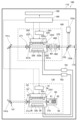
- FIG. 1 is a schematic diagram showing an example of the overall configuration of an electronic device manufacturing apparatus.
- FIG. 2 is a schematic diagram showing an example of the overall configuration of a gas laser device of a comparative example.
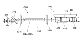
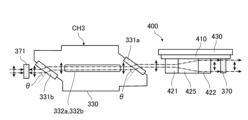
- FIG. 3 is a schematic diagram illustrating an example of a schematic configuration of the amplifier according to the first embodiment.
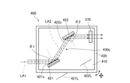
- FIG. 4 is a schematic diagram showing an example of the schematic configuration of a beam expander.
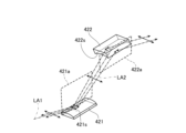
- FIG. 5 is a perspective view showing a convex mirror and a concave mirror of the first embodiment.
- FIG. 6 is a cross-sectional view of a convex mirror.
- FIG. 7 is a cross-sectional view of a concave mirror.
- FIG. 1 is a schematic diagram showing an example of the overall configuration of an electronic device manufacturing apparatus.
- FIG. 2 is a schematic diagram showing an example of the overall configuration of a gas laser device of a comparative example.
- FIG. 3 is a schematic diagram illustrating an example of a schematic configuration of the amplifier according to the
- FIG. 8 is a schematic diagram showing a schematic configuration example of an amplifier according to a modification of the first embodiment, similar to FIG.
- FIG. 9 is a schematic diagram showing a schematic configuration example of an amplifier according to the second embodiment, similar to FIG.
- FIG. 10 is a schematic diagram showing an example of the schematic configuration of a beam expander according to the second embodiment, similar to FIG.
- FIG. 11 is a perspective view showing a convex mirror, a plane mirror, and a concave mirror of the second embodiment, similar to FIG.
- FIG. 12 is a schematic diagram showing a schematic configuration example of an amplifier according to the third embodiment, similar to FIG.
- FIG. 13 is a schematic diagram showing a schematic configuration example of a beam expander according to the third embodiment, similar to FIG.
- FIG. 14 is a perspective view showing a convex mirror, two plane mirrors, and a concave mirror according to the third embodiment, similar to FIG.
- FIG. 1 is a schematic diagram showing an example of the overall schematic configuration of an electronic device manufacturing apparatus used in an exposure process of an electronic device.
- the manufacturing apparatus used in the exposure process includes a gas laser device 100 and an exposure device 200.
- the exposure device 200 includes an illumination optical system 210 including a plurality of mirrors 211, 212, and 213, and a projection optical system 220.
- the illumination optical system 210 illuminates a reticle pattern on a reticle stage RT with a laser beam incident from the gas laser device 100.
- the projection optical system 220 reduces and projects the laser beam transmitted through the reticle to form an image on a workpiece (not shown) placed on a workpiece table WT.
- the workpiece is a photosensitive substrate such as a semiconductor wafer on which a photoresist is applied.
- the exposure device 200 exposes the workpiece to laser beam reflecting the reticle pattern by synchronously moving the reticle stage RT and the workpiece table WT in parallel. By transferring a device pattern onto a semiconductor wafer through the above-described exposure process, a semiconductor device, which is an electronic device, can be manufactured.
- FIG. 2 is a schematic diagram showing an example of the overall schematic configuration of the gas laser device 100 of this embodiment.
- the gas laser device 100 is, for example, an ArF excimer laser device that uses a mixed gas containing argon (Ar), fluorine (F 2 ), and neon (Ne). This gas laser device 100 outputs a laser beam with a central wavelength of about 193.4 nm.
- the gas laser device 100 may be a gas laser device other than an ArF excimer laser device, for example, a KrF excimer laser device that uses a mixed gas containing krypton (Kr), F 2 , and Ne. In this case, the gas laser device 100 emits a laser beam with a central wavelength of about 248.0 nm.
- a mixed gas containing Ar, F 2 , and Ne as a laser medium, or a mixed gas containing Kr, F 2 , and Ne as a laser medium, may be called a laser gas.
- helium He
- Ne helium
- the gas laser device 100 of this example mainly comprises a housing 110, a laser oscillator 130 which is a master oscillator arranged in the internal space of the housing 110, an optical transmission unit 141, an amplifier 160 which is a power oscillator, a detection unit 153, a display unit 180, a processor 190, a laser gas exhaust device 701, and a laser gas supply device 703.
- the laser oscillator 130 mainly comprises a chamber device CH1, a charger 41, a pulse power module 43, a line narrowing module 60, and an output coupling mirror 70.
- FIG. 2 shows the internal configuration of the chamber device CH1 as viewed from a direction substantially perpendicular to the direction of travel of the laser light.
- the chamber device CH1 mainly comprises a housing 30, a pair of windows 31a, 31b, a pair of electrodes 32a, 32b, an insulating section 33, a feedthrough 34, and an electrode holder section 36.
- the above-mentioned laser gas is supplied to the internal space of the housing 30 from the laser gas supply device 703 via piping, and the laser gas is sealed in the internal space.
- the internal space is a space where light is generated by excitation of the laser medium in the laser gas. This light travels to the windows 31a and 31b.
- Window 31a is disposed on the front wall of housing 30 in the direction of travel of the laser light from gas laser device 100 to exposure device 200, and window 31b is disposed on the rear wall of housing 30 in the same direction of travel.
- Windows 31a and 31b are calcium fluoride substrates, and the inner and outer surfaces of windows 31a and 31b on housing 30 are flat. Note that windows 31a and 31b are not limited to being calcium fluoride substrates as long as they are capable of transmitting laser light.
- the electrodes 32a and 32b are arranged facing each other in the internal space of the housing 30, and the longitudinal direction of the electrodes 32a and 32b is along the direction of travel of light generated by a high voltage applied between the electrodes 32a and 32b.
- the space between the electrodes 32a and 32b in the housing 30 is sandwiched between the windows 31a and 31b.
- the electrodes 32a and 32b are discharge electrodes for exciting the laser medium by glow discharge.
- the electrode 32a is the cathode and the electrode 32b is the anode.
- the electrode 32a is supported by an insulating part 33.
- the insulating part 33 covers an opening formed in the housing 30.
- the insulating part 33 includes an insulator.
- a feedthrough 34 made of a conductive material is also disposed in the insulating part 33. The feedthrough 34 applies a voltage supplied from the pulse power module 43 to the electrode 32a.
- the electrode 32b is supported by an electrode holder part 36 and is electrically connected to the electrode holder part 36.
- the charger 41 is a DC power supply device that charges a capacitor (not shown) provided inside the pulse power module 43 with a predetermined voltage.
- the charger 41 is disposed outside the housing 30 and is connected to the pulse power module 43.
- the pulse power module 43 includes a switch (not shown) controlled by the processor 190. When the switch is turned from OFF to ON by the control, the pulse power module 43 is a voltage application circuit that boosts the voltage applied from the charger 41 to generate a pulsed high voltage and applies this high voltage to the electrodes 32a and 32b. When the high voltage is applied, a discharge occurs between the electrodes 32a and 32b. The energy of this discharge excites the laser medium in the housing 30.
- the windows 31a and 31b are inclined at a Brewster angle with respect to the traveling direction of the laser light so as to suppress reflection of the P-polarized light of the laser light.
- the windows are inclined with respect to a direction perpendicular to the traveling direction of the laser light and the direction in which the electrodes 32a and 32b face each other.
- the laser light emitted from the chamber device CH1 contains a first linearly polarized light whose polarization direction is perpendicular to the direction in which the electrodes 32a and 32b face each other, and linearly polarized light whose polarization direction is different from that of the first linearly polarized light is reduced from the laser light.
- the windows 31a and 31b are inclined with respect to the polarization direction of the first linearly polarized light, and also function as a polarizer that reduces linearly polarized light whose polarization direction is different from that of the first linearly polarized light from the laser light.
- perpendicular refers to an angle between 85 degrees and 95 degrees
- parallel refers to an angle within 5 degrees
- the line-narrowing module 60 includes a housing 65, a prism 61, a grating 63, and a rotating stage (not shown) that are arranged in the internal space of the housing 65.
- An opening is formed in the housing 65, and the housing 65 is connected to the rear side of the housing 30 via the opening.
- Prism 61 expands the beam width of the light exiting from window 31b and makes the light enter grating 63. Prism 61 also reduces the beam width of the light reflected from grating 63 and returns the light to the internal space of housing 30 via window 31b. Prism 61 is supported by a rotating stage and rotates by the rotating stage. Rotation of prism 61 changes the angle of incidence of the light with respect to grating 63. Therefore, by rotating prism 61, it is possible to select the wavelength of the light returning from grating 63 to housing 30 via prism 61.
- FIG. 2 shows an example in which one prism 61 is arranged, two or more prisms may be arranged.
- the surface of the grating 63 is made of a highly reflective material, and has numerous grooves at regular intervals on the surface.
- the grating 63 is a dispersive optical element.
- the cross-sectional shape of each groove is, for example, a right-angled triangle.
- Light entering the grating 63 from the prism 61 is reflected by these grooves and diffracted in a direction according to the wavelength of the light.
- the grating 63 is arranged in a Littrow arrangement so that the angle of incidence of the light entering the grating 63 from the prism 61 matches the angle of diffraction of the diffracted light of the desired wavelength. This allows the light of the desired wavelength to be returned to the housing 30 via the prism 61.
- the output coupling mirror 70 faces the window 31a, transmits a portion of the laser light emitted from the window 31a, and reflects the other portion back into the internal space of the housing 30 via the window 31a.
- the output coupling mirror 70 is fixed to a holder (not shown) and is disposed in the internal space of the housing 110.
- the grating 63 and output coupling mirror 70 which are provided on either side of the housing 30, form a Fabry-Perot type resonator, and the housing 30 is placed on the optical path of the resonator. Therefore, the resonator resonates light between both sides of the chamber device CH1.
- the optical transmission unit 141 mainly includes high-reflection mirrors 141b and 141c.
- the high-reflection mirrors 141b and 141c are fixed to holders (not shown) with their respective tilt angles adjusted, and are arranged in the internal space of the housing 110.
- the high-reflection mirrors 141b and 141c highly reflect the laser light.
- the high-reflection mirrors 141b and 141c are arranged on the optical path of the laser light from the output coupling mirror 70.
- the laser light is reflected by the high-reflection mirrors 141b and 141c and travels to the rear mirror 371 of the amplifier 160. At least a portion of this laser light passes through the rear mirror 371.
- the amplifier 160 amplifies the energy of the laser light output from the laser oscillator 130.
- the basic configuration of the amplifier 160 is generally the same as that of the laser oscillator 130.
- the chamber device, housing, pair of windows, pair of electrodes, insulating section, feedthrough, electrode holder section, charger, pulse power module, and output coupling mirror of the amplifier 160 will be described as the chamber device CH3, housing 330, pair of windows 331a, 331b, pair of electrodes 332a, 332b, insulating section 333, feedthrough 334, electrode holder section 336, charger 341, pulse power module 343, and output coupling mirror 370.
- the electrodes 332a, 332b generate a discharge for amplifying the laser light from the laser oscillator 130.
- the direction in which the electrodes 332a and 332b face each other is perpendicular to the direction in which the first linearly polarized light in the laser light from the laser oscillator 130 is changed.
- the windows 331a and 331b are tilted with respect to the polarization direction of the first linearly polarized light so that the first linearly polarized light in the laser light is incident as P-polarized light and the incidence angle ⁇ of the laser light is Brewster's angle.
- the laser light emitted from the chamber device CH3 contains the first linearly polarized light, and linearly polarized light having a polarization direction different from the polarization direction of the first linearly polarized light is reduced from the laser light.
- the windows 331a and 331b like the windows 31a and 31b, are tilted with respect to the polarization direction of the first linearly polarized light, and also serve as a polarizer that reduces linearly polarized light having a polarization direction different from the polarization direction of the first linearly polarized light from the laser light.
- the pulse power module 343 is a voltage application circuit like the pulse power module 43.
- the amplifier 160 also differs from the laser oscillator 130 mainly in that it does not include a line narrowing module 60, but includes a rear mirror 371 and a beam expander 400.
- the rear mirror 371 is provided between the high-reflection mirror 141c and the window 331b, facing each of them.
- the rear mirror 371 transmits a portion of the laser light from the laser oscillator 130 toward the space between the electrodes 332a, 332b, and reflects a portion of the laser light amplified by the electrodes 332a, 332b toward the space between the electrodes 332a, 332b.
- the output coupling mirror 370 is disposed on the opposite side of the chamber device CH3 from the rear mirror 371, and the beam expander 400 is disposed between the chamber device CH3 and the output coupling mirror 370.
- the beam expander 400 in this example includes two prisms 401 and 402.
- the prism 401 expands the beam width of the laser light emitted from the chamber device CH3.
- the prism 402 further expands the beam width of the light whose beam width has been expanded by the prism 401, and emits the light toward the output coupling mirror 370.
- the prism 402 also reduces the beam width of the reflected light from the output coupling mirror 370, and the prism 401 further reduces the beam width of the light whose beam width has been reduced by the prism 402, and returns the light to the internal space of the housing 330 via the window 331a.
- the direction in which the prisms 401 and 402 expand or reduce the beam width is perpendicular to the direction in which the electrodes 332a and 332b face each other.
- the surface of the output coupling mirror 370 facing the beam expander 400 is coated with a partially reflective film having a predetermined reflectivity.
- the output coupling mirror 370 reflects a portion of the laser light from the chamber device CH3, the beam width of which has been expanded by the beam expander 400, toward the beam expander 400, and transmits the other portion of the laser light.
- the output coupling mirror 370 may be circular.
- the surface of the output coupling mirror 370 facing the beam expander 400 and the surface opposite to that surface may be flat.
- the rear mirror 371 and the output coupling mirror 370 have a similar configuration to the output coupling mirror 70.
- the rear mirror 371 and the output coupling mirror 370 which are provided on either side of the housing 330, form a resonator that resonates the laser light amplified by the electrodes 332a and 332b.
- the housing 330 and the beam expander 400 are arranged on the optical path of the resonator.
- the laser light emitted from the window 331a of the housing 330 enters the output coupling mirror 370 via the beam expander 400 and is reflected by the output coupling mirror 370.
- the laser light reflected by the output coupling mirror 370 returns to the internal space of the housing 330 via the beam expander 400 and the window 331b, and is emitted from the window 331a.
- the laser light emitted from this window 331a is reflected by the rear mirror 371 and returns to the internal space of the housing 330 via the window 331b. In this way, the laser light emitted from the housing 330 travels back and forth between the rear mirror 371 and the output coupling mirror 370.
- the reciprocating laser light is amplified each time it passes through the laser gain space between electrodes 332a and 332b.
- the resonator resonates light between both sides of the chamber device CH3, and the output coupling mirror 370 is disposed on one side of the chamber device CH3. A portion of the amplified laser light passes through the output coupling mirror 370.
- the laser light that passes through the output coupling mirror 370 proceeds to the detection unit 153.
- the detection unit 153 mainly comprises a beam splitter 153b and an optical sensor 153c.
- Beam splitter 153b is disposed on the optical path of the laser light passing through output coupling mirror 370. Beam splitter 153b transmits the laser light passing through output coupling mirror 370 toward output window 173 with high transmittance, and also reflects a portion of the laser light toward the light receiving surface of optical sensor 153c.
- the optical sensor 153c measures the pulse energy of the laser light incident on the light receiving surface of the optical sensor 153c.
- the optical sensor 153c is electrically connected to the processor 190 and outputs a signal indicating the measured pulse energy to the processor 190.
- the processor 190 controls the voltage applied to the electrodes 32a and 32b of the amplifier 160 based on the signal.
- An exit window 173 is provided on the opposite side of the output coupling mirror 370 with respect to the beam splitter 153b of the detection unit 153.
- the exit window 173 is provided on the wall of the housing 110.
- the light that passes through the beam splitter 153b is emitted from the exit window 173 to the exposure device 200 outside the housing 110.
- This laser light is, for example, a pulsed laser light with a central wavelength of 193.4 nm.
- the display unit 180 is a monitor that displays the state of control by the processor 190 based on a signal from the processor 190.
- the display unit 180 may be disposed outside the housing 110.
- the processor 190 of the present disclosure is a processing device including a storage device in which a control program is stored, and a CPU (Central Processing Unit) that executes the control program.
- the processor 190 is specially configured or programmed to execute the various processes included in the present disclosure.
- the processor 190 also controls the entire gas laser device 100.
- the processor 190 is also electrically connected to an exposure processor (not shown) of the exposure device 200, and transmits and receives various signals to and from the exposure processor.
- the laser gas exhaust device 701 and the laser gas supply device 703 are electrically connected to the processor 190.
- the laser gas exhaust device 701 includes an exhaust pump (not shown), and exhausts laser gas from the internal space of the housings 30 and 330 through piping by suction of the exhaust pump in response to a control signal from the processor 190.
- the laser gas supply device 703 supplies laser gas from a laser gas supply source (not shown) located outside the housing 110 to the internal space of the housings 30 and 330 through piping in response to a control signal from the processor 190.
- laser gas is supplied from the laser gas supply device 703 to the internal space of the housings 30 and 330.
- the processor 190 receives a signal indicating the target energy Et and an emission trigger signal from an exposure processor (not shown) of the exposure device 200.
- the target energy Et is a target value of the energy of the laser light used in the exposure process.
- the processor 190 sets a predetermined charging voltage in the charger 41 so that the energy E becomes the target energy Et, and turns on the switch of the pulse power module 43 in synchronization with the emission trigger signal.
- the pulse power module 43 generates a pulsed high voltage from the electrical energy held in the charger 41, and the high voltage is applied between the electrodes 32a and 32b.
- the laser light contains a first linearly polarized light, and when passing through the windows 31a and 31b, linearly polarized light having a polarization direction different from the polarization direction of the first linearly polarized light is reduced from the laser light.
- a portion of the laser light passes through the output coupling mirror 70, is reflected by the high-reflection mirrors 141b and 141c, passes through the rear mirror 371 and the window 331b, and proceeds into the housing 330.
- the processor 190 switches on the pulse power module 343 so that a discharge occurs when the laser light from the laser oscillator 130 travels into the discharge space in the housing 330. That is, the processor 190 controls the pulse power module 343 so that a high voltage is applied to the electrodes 332a and 332b after a predetermined delay time has elapsed from the timing when the switch of the pulse power module 43 is switched on.
- the laser light incident on the amplifier 160 is amplified in the amplifier 160.
- the laser light that has traveled into the internal space of the housing 330 travels to the output coupling mirror 370 via the window 331a and the beam expander 400 as described above, and is reflected by the output coupling mirror 370.
- the laser light reflected by the output coupling mirror 370 travels through the beam expander 400 and the window 331a into the internal space of the housing 330 and is emitted from the window 331b.
- the light emitted from the window 331b is reflected by the rear mirror 371 and travels through the window 331b into the internal space of the housing 330.
- the laser light of a predetermined wavelength travels back and forth between the rear mirror 371 and the output coupling mirror 370.
- the laser light includes a first linearly polarized light, and when passing through the windows 331a and 331b, linearly polarized light having a polarization direction different from the polarization direction of the first linearly polarized light is reduced from the laser light.
- the laser light is amplified each time it passes through the discharge space inside the housing 330, and part of the laser light becomes amplified laser light.
- the amplified laser light from the amplifier 160 also passes through the output coupling mirror 370 and travels to the beam splitter 153b.
- a portion of the amplified laser light that reaches the beam splitter 153b passes through the beam splitter 153b and the exit window 173 and travels to the exposure device 200, while the other portion is reflected by the beam splitter 153b and travels to the optical sensor 153c.
- the optical sensor 153c measures the energy E of the received amplified laser light.
- the optical sensor 153c outputs a signal indicating the measured energy E to the processor 190.
- the processor 190 feedback controls the charging voltage of the charger 41, 341 so that the difference ⁇ E between the energy E and the target energy Et is within an acceptable range.
- the laser light whose difference ⁇ E is within an acceptable range passes through the beam splitter 153b and the exit window 173 and enters the exposure device 200.
- the beam expander 400 expands the beam width of the laser light emitted from the chamber device CH3 by using two prisms 401 and 402, and emits the light toward the output coupling mirror 370. This reduces the energy density of the laser light incident on the output coupling mirror 370, thereby suppressing deterioration over time of the output coupling mirror 370.
- the prisms 401 and 402 are transmissive optical elements, there is a concern that they may deteriorate over time due to transmitted light. There is also a demand for suppressing a decrease in the amount of laser light in the beam expander 400.
- the following embodiment illustrates a gas laser device that can suppress deterioration over time while also suppressing a decrease in light intensity.
- Fig. 3 is a schematic diagram showing a schematic configuration example of the amplifier 160 of the first embodiment, and is a schematic diagram of the amplifier 160 seen from the electrode 332a side along the direction in which the electrodes 332a and 332b face each other.
- the internal configuration of the chamber device CH3 is shown, and the polarization direction of the first linearly polarized light is indicated by a solid arrow.
- Fig. 4 is a schematic diagram showing a schematic configuration example of the beam expander 400, and is a schematic diagram of the beam expander 400 seen along the polarization direction of the first linearly polarized light. Therefore, in Fig. 4, the direction perpendicular to the paper surface is the polarization direction of the first linearly polarized light.
- the amplifier 160 of this embodiment differs from the amplifier 160 of the comparative example mainly in that the beam expander 400 includes a base member 410, a convex mirror 421, a concave mirror 422, and a drive mechanism 430.
- the base member 410 is a plate-like member extending in a direction parallel to the optical axis LA1 of the laser light emitted from the window 331a of the chamber device CH3.
- the base member 410 extends in a direction in which the electrodes 332a and 332b face each other, and the output coupling mirror 370 is disposed on one of the main surfaces of the base member 410.
- the convex mirror 421 includes a reflective surface 421s that reflects light, and reflects the laser light from the chamber device CH3 toward the concave mirror 422.
- the concave mirror 422 includes a reflective surface 422s that reflects light, and reflects the laser light reflected by the convex mirror 421 toward the output coupling mirror 370.
- the concave mirror 422 also reflects the laser light reflected by the output coupling mirror 370 toward the convex mirror 421, and the convex mirror 421 reflects the laser light reflected by the concave mirror 422 toward the chamber device CH3, and the laser light returns to the internal space of the housing 330 through the window 331a.
- the convex mirror 421 and the concave mirror 422 are disposed on one of the main surfaces of the base member 410.
- FIG. 5 is a perspective view showing the convex mirror 421 and concave mirror 422 of this embodiment.
- the polarization direction of the first linearly polarized light is indicated by a solid arrow.
- the convex mirror 421 is a convex cylindrical mirror
- the concave mirror 422 is a concave cylindrical mirror.
- FIG. 6 is a cross-sectional view of the convex mirror 421, the cross-section being parallel to the normal of the reflecting surface 421s of the convex mirror 421 and perpendicular to the incident plane of the laser light emitted from the window 331a onto the reflecting surface 421s.
- the shape of the reflecting surface 421s of the convex mirror 421 in the cross-section is a curve, which in this embodiment is an arc.
- FIG. 5 shows the incident plane 421a of the laser light along the optical axis LA1 onto the reflecting surface 421s.
- FIG. 7 is a cross-sectional view of concave mirror 422, the cross-section being parallel to the normal to reflecting surface 422s of concave mirror 422 and perpendicular to the incident plane of the laser light reflected by convex mirror 421 toward concave mirror 422 relative to reflecting surface 422s.
- the shape of reflecting surface 422s of concave mirror 422 in the cross-section is a curve, which in this embodiment is an arc.
- FIG. 5 shows incident plane 422a of the laser light along optical axis LA2 of the laser light reflected by convex mirror 421 relative to reflecting surface 422s.
- the focal line 421L of the convex mirror 421 is included in a plane that includes the optical axis LA1 of the laser light and extends in the direction in which the electrodes 332a and 332b face each other, and inclines so as to approach the electrode 332a as it moves away from the chamber device CH3.
- the focal line 422L of the concave mirror 422 is included in a plane that includes the optical axis LA1 of the laser light and the focal line 421L, and inclines so as to approach the electrode 332a as it moves away from the chamber device CH3.
- the focal line 421L of the convex mirror 421 and the focal line 422L of the concave mirror 422 are located on the same line.
- the incident angle ⁇ 1 of the laser light incident on the convex mirror 421 and the incident angle ⁇ 2 of the laser light incident on the concave mirror 422 are 45 degrees or more and 85 degrees or less. In other words, the positions of the convex mirror 421 and the concave mirror 422 are adjusted so that this is the case.
- focal line 421L is a line connecting the foci of convex mirror 421
- focal line 422L is a line connecting the foci of concave mirror 422.
- the driving mechanism 430 of this embodiment includes a rotation mechanism capable of rotating the base member 410 around an axis 430c perpendicular to the extension direction of the base member 410, and a movement mechanism capable of moving the base member 410 in a direction parallel to the extension direction of the base member 410. Therefore, by adjusting the position and orientation of the base member 410 relative to the chamber device CH3 using the driving mechanism 430, the positions and orientations of the convex mirror 421, concave mirror 422, and output coupling mirror 370 relative to the chamber device CH3 can be adjusted.
- a rotation mechanism is mounted on the movement mechanism, and the base member 410 is mounted on the rotation mechanism.
- the axis 430c overlaps with the center of gravity of the base member 410, but the position of the axis 430c is not limited to this.
- the output coupling mirror 370 has a rectangular shape that is elongated in a direction perpendicular to the direction in which the electrodes 332a, 332b face each other, and is disposed on one of the main surfaces of the base member 410.
- the shape of the output coupling mirror 370 is not limited, and may be, for example, a circular or elliptical shape.
- the convex mirror 421 When this laser light is emitted from the window 331a of the housing 330, it is reflected by the convex mirror 421 toward the concave mirror 422.
- the focal line 421L of the convex mirror 421 is included in a plane that includes the optical axis LA1 of the laser light and extends in the direction in which the electrodes 332a and 332b face each other.
- the laser light emitted from the window 331a is incident on the reflecting surface 421s so that the first linearly polarized light in the laser light becomes S-polarized light, and the beam width of the laser light is expanded in a direction perpendicular to the direction in which the electrodes 332a and 332b face each other.
- the polarization direction of the first linearly polarized light is perpendicular to the direction in which the electrodes 332a and 332b face each other, so the direction in which the beam width of the laser light is expanded is the same as the polarization direction of the first linearly polarized light.
- the laser light with the expanded beam width is reflected by the concave mirror 422 toward the output coupling mirror 370.
- the cross-sectional shape of the reflecting surface 422s of the concave mirror 422, which is parallel to the normal of the reflecting surface 422s and perpendicular to the plane of incidence of the laser light with the expanded beam width relative to the reflecting surface 422s, is an arc.
- the focal line 422L of the convex mirror 421 and the focal line 422L of the concave mirror 422 are included in the same plane including the optical axis LA1 of the laser light, and the focal line 421L and the focal line 422L are located on the same straight line.
- the laser light with the expanded beam width is incident on the reflecting surface 422s so that the first linearly polarized light in the laser light becomes S-polarized light, and is reflected by the reflecting surface 422s so that the expanded beam width is collimated to a constant value.
- the collimated laser light then enters the output coupling mirror 370.
- the laser light reflected by the output coupling mirror 370 is incident on the reflecting surface 422s so that the first linearly polarized light in the laser light becomes S-polarized light, and is reflected by the reflecting surface 422s toward the convex mirror 421.
- the beam width of this laser light is reduced in a direction perpendicular to the direction in which the electrodes 332a and 332b face each other.
- the laser light with the reduced beam width is incident on the reflecting surface 421s so that the first linearly polarized light in the laser light becomes S-polarized light, and is reflected by the reflecting surface 421s toward the window 331a.
- the laser light is collimated so that the reduced beam width is constant, and returns to the internal space of the housing 330 via the window 331a.
- the windows 331a and 331b of the chamber device CH3 are inclined with respect to the polarization direction of the first linearly polarized light, and also serve as polarizers that reduce linearly polarized light having a polarization direction different from the polarization direction of the first linearly polarized light from the laser light.
- the beam expander 400 of this embodiment includes a convex mirror 421 and a concave mirror 422.
- the laser light emitted from the chamber device CH3 is incident on a reflecting surface 421s of the convex mirror 421 so that the first linearly polarized light in the laser light becomes S-polarized light, and the reflecting surface 421s reflects the laser light so that the beam width of the laser light is expanded.
- the laser light reflected by the convex mirror 421 is incident on the reflecting surface 422s of the concave mirror 422 so that the first linearly polarized light in the laser light becomes S-polarized light, and the reflecting surface 422s reflects the laser light toward the output coupling mirror 370 so as to collimate the expanded beam width of the laser light to a constant value.
- optical elements that reflect light tend to be less susceptible to deterioration over time than optical elements that transmit light. Therefore, according to the gas laser device 100 of this embodiment, deterioration over time of the beam expander 400 can be suppressed compared to the case where the beam expander 400 is composed of the prisms 401 and 402 that transmit light, and as a result, deterioration over time of the gas laser device 100 can be suppressed.
- linearly polarized light different from the first linearly polarized light is reduced from the laser light by the windows 331a and 331b as polarizers, so that most of the polarized components contained in the amplified laser light become the first linearly polarized light.
- Such laser light is incident on the reflecting surface 421s of the convex mirror 421 and the reflecting surface 422s of the concave mirror 422 so that the first linearly polarized light in the laser light becomes S-polarized light and is reflected.
- the reflectance of S-polarized light tends to be higher than that of P-polarized light. Therefore, according to the gas laser device 100 of this embodiment, it is possible to suppress a decrease in the amount of light at the reflecting surface 421s and the reflecting surface 422s, compared to a case in which the laser light is incident on the reflecting surface 421s and the reflecting surface 422s so that the first linearly polarized light in the laser light becomes P-polarized light and is reflected. Therefore, according to the gas laser device 100 of this embodiment, it is possible to suppress a decrease in the amount of light while suppressing deterioration over time.
- the only components that reflect the laser light from the chamber device CH3 to the output coupling mirror 370 are the convex mirror 421 and the concave mirror 422, and the laser light is reflected twice. Therefore, according to the gas laser device 100 of this embodiment, it is possible to prevent inversion of the beam profile due to reflection between the laser light traveling from the chamber device CH3 to the convex mirror 421 and the laser light traveling from the concave mirror 422 to the output coupling mirror 370.
- the beam expander 400 of this embodiment further includes a plate-shaped base member 410 extending in a direction parallel to the optical axis LA1 of the laser light traveling from the chamber device CH3 toward the convex mirror 421.
- the convex mirror 421, the concave mirror 422, and the output coupling mirror 370 are disposed on one main surface of the base member 410.
- the base member 410 by disposing the base member 410 at their design positions, the convex mirror 421, the concave mirror 422, and the output coupling mirror 370 can each be disposed at their design positions. Therefore, according to the gas laser device 100 of this embodiment, these members can be disposed at their respective design positions more easily than when these members are disposed individually.
- the focal line 421L of the convex mirror 421 and the focal line 422L of the concave mirror 422 are included in the same plane including the optical axis LA1 of the laser light. Therefore, according to the gas laser device 100 of this embodiment, the convex mirror 421 and the concave mirror 422 can be designed more easily than when the focal lines 421L and 422L are not included in the same plane including the optical axis LA1 of the laser light. Note that at least one of the focal lines 421L and 422L does not have to be included in the same plane including the optical axis LA1 of the laser light. Also, in this embodiment, the focal lines 421L and 422L are located on the same straight line, but the focal lines 421L and 422L do not have to be located on the same straight line.
- the cross-sectional shape of the reflecting surface 421s of the convex mirror 421, which is parallel to the normal of the reflecting surface 421s and perpendicular to the plane of incidence of the laser light emitted from the window 331a to the reflecting surface 421s, is an arc.
- the cross-sectional shape of the reflecting surface 421s is not limited as long as the reflecting surface 421s reflects the laser light emitted from the chamber device CH3 so that the first linearly polarized light in the laser light becomes S-polarized light and the beam width of the laser light is expanded.
- the cross-sectional shape of the reflecting surface 421s may be a curve, or may be a parabola.
- the cross-sectional shape of the reflecting surface 422s of the concave mirror 422, which is parallel to the normal of the reflecting surface 422s and perpendicular to the plane of incidence of the laser light reflected by the convex mirror 421 relative to the reflecting surface 422s, is an arc.
- the cross-sectional shape is not limited to the above as long as the reflecting surface 421s reflects the laser light reflected by the convex mirror 421 toward the output coupling mirror 370 so as to collimate the laser light reflected by the convex mirror 421 so that the first linearly polarized light in the laser light becomes S-polarized light and the expanded beam width of the laser light is constant.
- the cross-sectional shape of the reflecting surface 422s may be a curve, or may be a parabola.
- the convex mirror 421 reflects the laser light emitted from the chamber device CH3 so that the beam width in the direction perpendicular to the direction in which the electrodes 332a, 332b face each other is expanded.
- the direction of the beam width expanded by the convex mirror 421 is not limited.
- the direction of the beam width expanded by the convex mirror 421 may be the direction in which the electrodes 332a, 332b face each other.
- the direction of the beam width expanded by the convex mirror 421 may be the same as the polarization direction of the first linearly polarized light, or may be different.
- the polarization direction of the first linearly polarized light is perpendicular to the direction in which the electrodes 332a, 332b face each other, and the direction of the beam width expanded by the convex mirror 421 is the same as the polarization direction of the first linearly polarized light.
- the polarization direction of the first linearly polarized light is not limited.
- the polarization direction of the first linearly polarized light may be the direction in which the electrodes 332a, 332b face each other, and the direction of the beam width expanded by the convex mirror 421 may be different from the polarization direction of the first linearly polarized light.
- the incidence angle ⁇ of the laser light entering the windows 331a and 331b is the Brewster angle.
- the windows 331a and 331b only need to reduce linearly polarized light whose polarization direction is different from that of the first linearly polarized light from the laser light, and the incidence angle ⁇ of the laser light is not limited.
- the windows 331a and 331b may be tilted with respect to the polarization direction of the first linearly polarized light so that the first linearly polarized light in the laser light enters as P-polarized light and the incidence angle ⁇ of the laser light is 25 degrees or more and 75 degrees or less, and this incidence angle ⁇ may be 25 degrees or more and 68 degrees or less.
- the incidence angle ⁇ By setting the incidence angle ⁇ to 25 degrees or more and 75 degrees or less, linearly polarized light whose polarization direction is different from that of the first linearly polarized light can be reduced.
- the transmittance of the first linearly polarized light can be made 97% or more, and it can be made easier to reduce linearly polarized light whose polarization direction is different from that of the first linearly polarized light from the laser light.
- the convex mirror 421, the concave mirror 422, and the output coupling mirror 370 are arranged on the base member 410, but the members on which these members are arranged are not limited.
- the convex mirror 421, the concave mirror 422, and the output coupling mirror 370 may each be arranged on a different holder.
- the beam expander 400 does not need to include the base member 410 and the drive mechanism 430.
- the incidence angle ⁇ 1 of the laser light incident on the convex mirror 421 and the incidence angle ⁇ 2 of the laser light incident on the concave mirror 422 are 45 degrees or more and 85 degrees or less.
- the energy density of the laser light at the convex mirror 421 and the concave mirror 422 can be made less likely to become high, and the convex mirror 421 and the concave mirror 422 can be made less susceptible to deterioration over time.
- the convex mirror 421 and the concave mirror 422 can be made less large. Note that these incidence angles ⁇ 1 and ⁇ 2 may be less than 45 degrees or greater than 85 degrees.
- Fig. 8 is a schematic diagram showing a schematic configuration example of an amplifier 160 in a modification of this embodiment, similar to Fig. 3.
- the amplifier 160 of this modification is mainly different from the amplifier 160 of the above embodiment in that it includes a polarizer 372 and that the windows 331a and 331b are arranged so as to be approximately perpendicular to the traveling direction of the laser light.
- the polarizer 372 of this modified example is a calcium fluoride substrate, like the windows 331a and 331b, and is disposed between the rear mirror 371 and the window 331b on the optical path of the resonator.
- the surface of the polarizer 372 facing the rear mirror 371 and the surface facing the window 331b are flat.
- the polarizer 372 is tilted to form a Brewster angle with respect to the polarization direction of the first linearly polarized light so that the first linearly polarized light in the laser light is incident as P-polarized light and reflection of the P-polarized light is suppressed.
- the degree of freedom of the configuration of the housing 330 of the chamber device CH3 can be improved compared to the case where the windows 331a and 331b of the chamber device CH3 reduce linearly polarized light different from the first linearly polarized light from the laser light as in the above embodiment.
- the windows 331a and 331b are inclined with respect to the polarization direction of the first linearly polarized light as in the above embodiment, and also serve as polarizers that reduce linearly polarized light having a polarization direction different from the polarization direction of the first linearly polarized light from the laser light.
- the polarizer 372 may be disposed on the optical path of the resonator, for example, between the window 331a and the convex mirror 421, or between the concave mirror 422 and the output coupling mirror 370.
- the number of polarizers 372 is not limited, and the polarizers 372 may be disposed in at least two locations, for example, between the rear mirror 371 and the window 331b, between the window 331a and the convex mirror 421, and between the concave mirror 422 and the output coupling mirror 370.
- the polarizer 372 may be a substrate that is transparent to laser light, and is not limited to a calcium fluoride substrate.
- the polarizer 372 only needs to reduce linearly polarized light having a polarization direction different from that of the first linearly polarized light from the laser light, and the incidence angle ⁇ a of the laser light incident on the polarizer 372 is not limited to the Brewster angle.
- the polarizer 372 may be tilted with respect to the polarization direction of the first linearly polarized light so that the incidence angle ⁇ a of the laser light is 25 degrees or more and 75 degrees or less, or may be tilted with respect to the polarization direction of the first linearly polarized light so that the incidence angle ⁇ a of the laser light is 25 degrees or more and 68 degrees or less.
- linearly polarized light having a polarization direction different from that of the first linearly polarized light can be reduced.
- the transmittance of the first linearly polarized light can be made 97% or more, and linearly polarized light having a polarization direction different from that of the first linearly polarized light can be more easily reduced from the laser light.
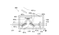
- FIG. 9 is a schematic diagram showing an example of the schematic configuration of the amplifier 160 of this embodiment in the same manner as FIG. 3, and
- FIG. 10 is a schematic diagram showing an example of the schematic configuration of the beam expander 400 of this embodiment in the same manner as FIG.
- the amplifier 160 of this embodiment differs from the amplifier 160 of embodiment 1 mainly in that the beam expander 400 further includes a plane mirror 425.
- the convex mirror 421 reflects the laser light from the chamber device CH3 toward the plane mirror 425.
- the plane mirror 425 includes a flat reflecting surface 425s that reflects light, and reflects the laser light reflected by the convex mirror 421 toward the concave mirror 422.
- the concave mirror 422 reflects the laser light reflected by the plane mirror 425 toward the output coupling mirror 370.
- the concave mirror 422 also reflects the laser light reflected by the output coupling mirror 370 toward the plane mirror 425, and the plane mirror 425 reflects the laser light reflected by the concave mirror 422 toward the convex mirror 421, and the convex mirror 421 reflects the laser light reflected by the plane mirror 425 toward the chamber device CH3.
- the convex mirror 421, the plane mirror 425, the concave mirror 422, and the output coupling mirror 370 are disposed on one main surface of the base member 410.
- the focal line 421L of the convex mirror 421 is included in a plane that includes the optical axis LA1 of the laser light and extends in the direction in which the electrodes 332a and 332b face each other, and is inclined so as to approach the electrode 332a as it moves away from the chamber device CH3.
- the focal line 422L of the concave mirror 422 is included in a plane that includes the optical axis LA1 of the laser light and the focal line 421L, and is inclined so as to approach the electrode 332b as it moves away from the chamber device CH3.
- the focal line 421Lv in the virtual image 421v of the convex mirror 421 created by the reflecting surface 425s of the plane mirror 425 and the focal line 422L of the concave mirror 422 are located on the same line.
- the optical axis LA1 of the laser light traveling from the chamber device CH3 to the convex mirror 421 and the optical axis LA3 of the laser light traveling from the concave mirror 422 to the output coupling mirror 370 are located on the same line.
- the incidence angle ⁇ 1 of the laser light incident on the convex mirror 421 and the incidence angle ⁇ 2 of the laser light incident on the concave mirror 422 are 45 degrees or more and 85 degrees or less.
- the positions of the convex mirror 421, the plane mirror 425, and the concave mirror 422 are adjusted in this manner.
- the virtual image 421v and the focal line 421Lv in the virtual image 421v are indicated by dashed lines.
- Fig. 11 is a perspective view showing the convex mirror 421, the plane mirror 425, and the concave mirror 422 of this embodiment in the same manner as Fig. 5.
- the laser light emitted from the window 331a is incident on the reflecting surface 421s of the convex mirror 421 so that the first linearly polarized light in the laser light becomes S-polarized light, and the beam width of the laser light is expanded in a direction perpendicular to the direction in which the electrodes 332a and 332b face each other.
- the direction in which the beam width of the laser light is expanded is the same as the polarization direction of the first linearly polarized light.
- the laser light with the expanded beam width is incident on the reflecting surface 425s of the plane mirror 425 so that the first linearly polarized light in the laser light becomes S-polarized light, and is reflected by the reflecting surface 425s toward the concave mirror 422.
- the focal line 421Lv in the virtual image 421v and the focal line 422L of the concave mirror 422 are located on the same straight line. Therefore, the laser light reflected by the plane mirror 425 is incident on the reflecting surface 422s of the concave mirror 422 so that the first linearly polarized light in the laser light becomes S-polarized light, and is reflected by the reflecting surface 422s so that the expanded beam width is collimated to a constant value. The collimated laser light then enters the output coupling mirror 370.
- the laser light reflected by the output coupling mirror 370 is incident on the reflecting surface 422s so that the first linearly polarized light in the laser light becomes S-polarized light, and is reflected by the reflecting surface 422s toward the plane mirror 425.
- the beam width of this laser light is reduced in a direction perpendicular to the direction in which the electrodes 332a and 332b face each other.
- the laser light with the reduced beam width is incident on the reflecting surface 425s so that the first linearly polarized light in the laser light becomes S-polarized light, and is reflected by the reflecting surface 425s toward the convex mirror 421.
- the laser light reflected by the reflecting surface 425s is incident on the reflecting surface 421s so that the first linearly polarized light in the laser light becomes S-polarized light, and is reflected by the reflecting surface 421s toward the window 331a.
- the laser light is collimated so that the reduced beam width is constant, and returns to the internal space of the housing 330 via the window 331a.
- the laser light emitted from the chamber device CH3 is reflected by the convex mirror 421, the plane mirror 425, and the concave mirror 422 in this order, and the beam width of the laser light is expanded. Then, the laser light with the expanded beam width is incident on the output coupling mirror 370. Therefore, according to the gas laser device 100 of this embodiment, the deterioration of the beam expander 400 over time can be suppressed compared to the case where the beam expander 400 is composed of the prisms 401 and 402 that transmit light.
- the decrease in the amount of light at the reflecting surfaces 421s, 425s, and 422s can be suppressed compared to the case where the laser light is incident on and reflected by the reflecting surfaces 421s, 425s, and 422s so that the first linearly polarized light in the laser light becomes P-polarized light.
- the beam expander 400 can be prevented from expanding in the direction in which the convex mirror 421 reflects the laser light from the chamber apparatus CH3.
- the convex mirror 421, the plane mirror 425, the concave mirror 422, and the output coupling mirror 370 are arranged on one main surface of the base member 410. Therefore, by arranging the base member 410 in the design position, the convex mirror 421, the plane mirror 425, the concave mirror 422, and the output coupling mirror 370 can be arranged in their respective design positions. Therefore, according to the gas laser device 100 of this embodiment, these components can be easily arranged in their respective design positions compared to the case where these components are arranged individually. Note that the components on which these components are arranged are not limited.
- the convex mirror 421, the plane mirror 425, the concave mirror 422, and the output coupling mirror 370 may each be arranged in a different holder.
- the beam expander 400 does not need to include the base member 410 and the drive mechanism 430.
- the focal line 421Lv in the virtual image 421v created by the reflecting surface 425s of the plane mirror 425 and the focal line 422L of the concave mirror 422 are located on the same straight line, but the focal line 421Lv and the focal line 422L do not have to be located on the same straight line.
- the optical axis LA1 of the laser light traveling from the chamber device CH3 to the convex mirror 421 and the optical axis LA3 of the laser light traveling from the concave mirror 422 to the output coupling mirror 370 are positioned on the same straight line. Therefore, for example, the beam expander 400 can be placed in the existing amplifier 160 without changing the design positions of the chamber device CH3 or the output coupling mirror 370. Note that the optical axis LA1 and the optical axis LA3 do not have to be positioned on the same straight line.
- the incidence angle ⁇ 1 of the laser light incident on the convex mirror 421 and the incidence angle ⁇ 2 of the laser light incident on the concave mirror 422 are 45 degrees or more and 85 degrees or less. This can prevent the convex mirror 421 and the concave mirror 422 from deteriorating easily over time, and can prevent the convex mirror 421 and the concave mirror 422 from becoming too large. Note that these incidence angles ⁇ 1 and ⁇ 2 may be less than 45 degrees or more than 85 degrees. Furthermore, the incidence angle of the laser light incident on the plane mirror 425 may be 45 degrees or more and 85 degrees or less, or it may be less than 45 degrees or more than 85 degrees.
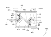
- FIG. 12 is a schematic diagram showing an example of the schematic configuration of the amplifier 160 of this embodiment in the same manner as FIG. 3, and
- FIG. 13 is a schematic diagram showing an example of the schematic configuration of the beam expander 400 of this embodiment in the same manner as FIG.
- the amplifier 160 of this embodiment differs from the amplifier 160 of embodiment 2 mainly in that the beam expander 400 further includes a plane mirror 426.
- the convex mirror 421 reflects the laser light from the chamber device CH3 toward the first plane mirror 425.
- the first plane mirror 425 includes a planar reflecting surface 425s that reflects light, and reflects the laser light reflected by the convex mirror 421 toward the second plane mirror 426.
- the second plane mirror 426 includes a planar reflecting surface 426s that reflects light, and reflects the laser light reflected by the first plane mirror 425 toward the concave mirror 422.
- the concave mirror 422 reflects the laser light reflected by the second plane mirror 426 toward the output coupling mirror 370.
- the concave mirror 422 reflects the laser light reflected by the output coupling mirror 370 toward the second plane mirror 426
- the second plane mirror 426 reflects the laser light reflected by the concave mirror 422 toward the first plane mirror 425.
- the first plane mirror 425 reflects the laser light reflected by the second plane mirror 426 toward the convex mirror 421, and the convex mirror 421 reflects the laser light reflected by the first plane mirror 425 toward the chamber device CH3.
- the convex mirror 421, the first plane mirror 425, the second plane mirror 426, the concave mirror 422, and the output coupling mirror 370 are arranged on one main surface of the base member 410.
- the focal line 421L of the convex mirror 421 is included in a plane that includes the optical axis LA1 of the laser light and extends in the direction in which the electrodes 332a and 332b face each other, and is inclined so as to approach the electrode 332a as it moves away from the chamber device CH3.
- the focal line 422L of the concave mirror 422 is included in a plane that includes the optical axis LA1 of the laser light and the focal line 421L, and is inclined so as to approach the electrode 332b as it moves away from the chamber device CH3.
- the focal line 421Lv in the virtual image 421v of the convex mirror 421 created by the reflecting surface 425s of the first plane mirror 425 and the focal line 422Lv in the virtual image 422v of the concave mirror 422 created by the reflecting surface 426s of the second plane mirror 426 are located on the same straight line.
- the optical axis LA1 of the laser light traveling from the chamber device CH3 to the convex mirror 421 and the optical axis LA3 of the laser light traveling from the concave mirror 422 to the output coupling mirror 370 are aligned on the same straight line. That is, the positions of the convex mirror 421, the plane mirror 425, and the concave mirror 422 are adjusted so that this is the case.
- the virtual image 421v and the focal line 421Lv in the virtual image 421v, and the virtual image 422v and the focal line 422Lv in the virtual image 422v are indicated by dashed lines.
- the laser light emitted from the window 331a is incident on the reflecting surface 421s of the convex mirror 421 so that the first linearly polarized light in the laser light becomes S-polarized light, and the beam width of the laser light is expanded in a direction perpendicular to the direction in which the electrodes 332a and 332b face each other.
- the direction in which the beam width of the laser light is expanded is the same as the polarization direction of the first linearly polarized light.
- the laser light with the expanded beam width is incident on the reflecting surface 425s of the first plane mirror 425 so that the first linearly polarized light in the laser light becomes S-polarized light, and is reflected by the reflecting surface 425s toward the second plane mirror 426.
- the laser light reflected by the first plane mirror 425 is incident on the reflecting surface 426s of the second plane mirror 426 so that the first linearly polarized light in the laser light becomes S-polarized light, and is reflected by the reflecting surface 426s toward the concave mirror 422.
- the focal line 421Lv in the virtual image 421v and the focal line 422Lv in the virtual image 422v are located on the same line.
- the laser light reflected by the second plane mirror 426 is incident on the reflecting surface 422s of the concave mirror 422 so that the first linearly polarized light in the laser light becomes S-polarized light, and is reflected by the reflecting surface 422s so that the expanded beam width is collimated to a constant value.
- the collimated laser light then enters the output coupling mirror 370.
- the laser light reflected by output coupling mirror 370 is incident on reflecting surface 422s so that the first linearly polarized light in the laser light becomes S-polarized light, and is reflected by reflecting surface 422s toward second plane mirror 426.
- the beam width of this laser light is reduced in a direction perpendicular to the direction in which electrodes 332a, 332b face each other.
- the laser light with the reduced beam width is incident on reflecting surface 426s so that the first linearly polarized light in the laser light becomes S-polarized light, and is reflected by reflecting surface 426s toward first plane mirror 425.
- the laser light reflected by reflecting surface 426s is incident on reflecting surface 425s so that the first linearly polarized light in the laser light becomes S-polarized light, and is reflected by reflecting surface 425s toward concave mirror 422.
- the laser light reflected by the reflecting surface 425s is incident on the reflecting surface 421s so that the first linearly polarized light in the laser light becomes S-polarized light, and is reflected by the reflecting surface 421s toward the window 331a.
- This laser light is collimated so that the reduced beam width is constant, and returns to the internal space of the housing 330 through the window 331a.
- the laser light emitted from the chamber device CH3 is reflected by the convex mirror 421, the first plane mirror 425, the second plane mirror 426, and the concave mirror 422 in that order, and the beam width of the laser light is expanded.
- the laser light with the expanded beam width then enters the output coupling mirror 370. Therefore, according to the gas laser device 100 of this embodiment, deterioration over time of the beam expander 400 can be suppressed compared to when the beam expander 400 is made up of the prisms 401 and 402 that transmit light.
- a decrease in the amount of light at reflecting surfaces 421s, 425s, 426s, and 422s can be suppressed, compared to, for example, a case in which laser light is incident on and reflected by reflecting surfaces 421s, 425s, 426s, and 422s so that the first linear polarization in the laser light becomes P polarization.
- the convex mirror 421, the first plane mirror 425, the second plane mirror 426, the concave mirror 422, and the output coupling mirror 370 are arranged on one main surface of the base member 410. Therefore, by arranging the base member 410 in the design position, the convex mirror 421, the first plane mirror 425, the second plane mirror 426, the concave mirror 422, and the output coupling mirror 370 can be arranged in their respective design positions. Therefore, according to the gas laser device 100 of this embodiment, these components can be easily arranged in their respective design positions compared to the case where these components are arranged individually. Note that the components on which these components are arranged are not limited.
- the convex mirror 421, the first plane mirror 425, the second plane mirror 426, the concave mirror 422, and the output coupling mirror 370 may each be arranged in a holder different from each other. Additionally, the beam expander 400 does not need to include the base member 410 and the drive mechanism 430.
- the only components that reflect the laser light from the chamber device CH3 to the output coupling mirror 370 are the convex mirror 421, the first plane mirror 425, the second plane mirror 426, and the concave mirror 422, and the laser light is reflected four times. Therefore, according to the gas laser device 100 of this embodiment, it is possible to prevent inversion of the beam profile due to reflection between the laser light traveling from the chamber device CH3 to the convex mirror 421 and the laser light traveling from the concave mirror 422 to the output coupling mirror 370.
- focal line 421Lv in virtual image 421v and focal line 422Lv in virtual image 422v are located on the same straight line, but focal line 421Lv and focal line 422Lv do not have to be located on the same straight line.
- the optical axis LA1 of the laser light traveling from the chamber device CH3 to the convex mirror 421 and the optical axis LA3 of the laser light traveling from the concave mirror 422 to the output coupling mirror 370 are positioned on the same straight line. Therefore, for example, the beam expander 400 can be placed in the existing amplifier 160 without changing the design positions of the chamber device CH3 or the output coupling mirror 370. Note that the optical axis LA1 and the optical axis LA3 do not have to be positioned on the same straight line.
- the angle of incidence of the laser light incident on the convex mirror 421 and the angle of incidence of the laser light incident on the concave mirror 422 may be 45 degrees or more and 85 degrees or less, or may be less than 45 degrees, or may be greater than 85 degrees, as in embodiment 1.
- the angle of incidence of the laser light incident on the first plane mirror 425 and the angle of incidence of the laser light incident on the second plane mirror 426 may be 45 degrees or more and 85 degrees or less, or may be less than 45 degrees, or may be greater than 85 degrees.
Landscapes
- Physics & Mathematics (AREA)
- Electromagnetism (AREA)
- Optics & Photonics (AREA)
- Engineering & Computer Science (AREA)
- Plasma & Fusion (AREA)
- General Physics & Mathematics (AREA)
- Lasers (AREA)
Abstract
ガスレーザ装置は、レーザ発振器から出力されるレーザ光を増幅器で増幅して出射するガスレーザ装置であって、増幅器は、レーザ光を増幅するチャンバ装置と、レーザ光をチャンバ装置を挟む両側間で共振させ共振器と、レーザ光から第1の直線偏光の偏光方向と異なる偏光方向の直線偏光を減少させる偏光子と、ビームエキスパンダと、を備え、共振器は、出力結合ミラーを含み、ビームエキスパンダは、チャンバ装置から出射するレーザ光が当該レーザ光における第1の直線偏光がS偏光となるように入射し当該レーザ光のビーム幅が拡大するように当該レーザ光を反射する反射面を含む凸面鏡と、凸面鏡で反射されたレーザ光が当該レーザ光における第1の直線偏光がS偏光となるように入射し当該レーザ光の拡大されたビーム幅が一定となるようなコリメートをするように当該レーザ光を出力結合ミラーに向かって反射する反射面を含む凹面鏡と、を含む。
Description
本開示は、ガスレーザ装置、及び電子デバイスの製造方法に関する。
近年、半導体露光装置においては、半導体集積回路の微細化及び高集積化につれて、解像力の向上が要請されている。このため、露光用光源から放出される光の短波長化が進められている。例えば、露光用のガスレーザ装置としては、波長約248.0nmのレーザ光を出力するKrFエキシマレーザ装置、ならびに波長約193.4nmのレーザ光を出力するArFエキシマレーザ装置が用いられる。
KrFエキシマレーザ装置及びArFエキシマレーザ装置の自然発振光のスペクトル線幅は、350pm~400pmと広い。そのため、KrF及びArFレーザ光のような紫外線を透過する材料で投影レンズを構成すると、色収差が発生してしまう場合がある。その結果、解像力が低下し得る。そこで、ガスレーザ装置から出力されるレーザ光のスペクトル線幅を、色収差が無視できる程度となるまで狭帯域化する必要がある。そのため、ガスレーザ装置のレーザ共振器内には、スペクトル線幅を狭帯域化するために、狭帯域化素子(エタロンやグレーティング等)を含む狭帯域化モジュール(Line Narrowing Module:LNM)が備えられる場合がある。以下では、スペクトル線幅が狭帯域化されるガスレーザ装置を狭帯域化ガスレーザ装置という。
本開示の一態様によるガスレーザ装置は、レーザ発振器から出力されるレーザ光を増幅器で増幅して出射するガスレーザ装置であって、増幅器は、レーザ発振器からのレーザ光が透過すると共にレーザガスが封入される内部空間に互いに対向する一対の放電電極を含み、一対の放電電極間に電圧が印加されることでレーザ発振器からのレーザ光を増幅するチャンバ装置と、チャンバ装置から出射するレーザ光をチャンバ装置を挟む両側間で共振させる共振器と、共振器のレーザ光の光路上に配置され、レーザ光から第1の直線偏光の偏光方向と異なる偏光方向の直線偏光を減少させる偏光子と、ビームエキスパンダと、を備え、共振器は、チャンバ装置を挟む一方側に配置され、チャンバ装置から出射するレーザ光の一部を透過させ、チャンバ装置から出射するレーザ光の他の一部をチャンバ装置に戻すように反射する出力結合ミラーを含み、ビームエキスパンダは、チャンバ装置と出力結合ミラーとの間に配置され、チャンバ装置から出射するレーザ光が当該レーザ光における第1の直線偏光がS偏光となるように入射し当該レーザ光のビーム幅が拡大するように当該レーザ光を反射する反射面を含む凸面鏡と、凸面鏡で反射されたレーザ光が当該レーザ光における第1の直線偏光がS偏光となるように入射し当該レーザ光の拡大されたビーム幅が一定となるようなコリメートをするように当該レーザ光を出力結合ミラーに向かって反射する反射面を含む凹面鏡と、を含んでもよい。
本開示の一態様による電子デバイスの製造方法は、レーザ発振器から出力されるレーザ光を増幅器で増幅して出射するガスレーザ装置であって、増幅器は、レーザ発振器からのレーザ光が透過すると共にレーザガスが封入される内部空間に互いに対向する一対の放電電極を含み、一対の放電電極間に電圧が印加されることでレーザ発振器からのレーザ光を増幅するチャンバ装置と、チャンバ装置から出射するレーザ光をチャンバ装置を挟む両側間で共振させる共振器と、共振器のレーザ光の光路上に配置され、レーザ光から第1の直線偏光の偏光方向と異なる偏光方向の直線偏光を減少させる偏光子と、ビームエキスパンダと、を備え、共振器は、チャンバ装置を挟む一方側に配置され、チャンバ装置から出射するレーザ光の一部を透過させ、チャンバ装置から出射するレーザ光の他の一部をチャンバ装置に戻すように反射する出力結合ミラーを含み、ビームエキスパンダは、チャンバ装置と出力結合ミラーとの間に配置され、チャンバ装置から出射するレーザ光が当該レーザ光における第1の直線偏光がS偏光となるように入射し当該レーザ光のビーム幅が拡大するように当該レーザ光を反射する反射面を含む凸面鏡と、凸面鏡で反射されたレーザ光が当該レーザ光における第1の直線偏光がS偏光となるように入射し当該レーザ光の拡大されたビーム幅が一定となるようなコリメートをするように当該レーザ光を出力結合ミラーに向かって反射する反射面を含む凹面鏡と、を含むガスレーザ装置によってパルスレーザ光を生成し、パルスレーザ光を露光装置に出力し、電子デバイスを製造するために、露光装置内で感光基板上にパルスレーザ光を露光してもよい。
本開示のいくつかの実施形態を、単なる例として、添付の図面を参照して以下に説明する。
図1は、電子デバイスの製造装置の全体の概略構成例を示す模式図である。
図2は、比較例のガスレーザ装置の全体の概略構成例を示す模式図である。
図3は、実施形態1の増幅器の概略構成例を示す模式図である。
図4は、ビームエキスパンダの概略構成例を示す模式図である。
図5は、実施形態1の凸面鏡及び凹面鏡を示す斜視図である。
図6は、凸面鏡の断面図である。
図7は、凹面鏡の断面図である。
図8は、実施形態1の変形例における増幅器の概略構成例を図3と同様に示す模式図である。
図9は、実施形態2の増幅器の概略構成例を図3と同様に示す模式図である。
図10は、実施形態2のビームエキスパンダの概略構成例を図4と同様に示す模式図である。
図11は、実施形態2の凸面鏡、平面鏡、及び凹面鏡を図5と同様に示す斜視図である。
図12は、実施形態3の増幅器の概略構成例を図3と同様に示す模式図である。
図13は、実施形態3のビームエキスパンダの概略構成例を図4と同様に示す模式図である。
図14は、実施形態3の凸面鏡、2つの平面鏡、及び凹面鏡を図5と同様に示す斜視図である。
1.電子デバイスの露光工程で使用される電子デバイスの製造装置の説明
2.比較例のガスレーザ装置の説明
2.1 構成
2.2 動作
2.3 課題
3.実施形態1のガスレーザ装置の説明
3.1 構成
3.2 動作
3.3 作用・効果
3.4 変形例
4.実施形態2のガスレーザ装置の説明
4.1 構成
4.2 動作
4.3 作用・効果
5.実施形態3のガスレーザ装置の説明
5.1 構成
5.2 動作
5.3 作用・効果
2.比較例のガスレーザ装置の説明
2.1 構成
2.2 動作
2.3 課題
3.実施形態1のガスレーザ装置の説明
3.1 構成
3.2 動作
3.3 作用・効果
3.4 変形例
4.実施形態2のガスレーザ装置の説明
4.1 構成
4.2 動作
4.3 作用・効果
5.実施形態3のガスレーザ装置の説明
5.1 構成
5.2 動作
5.3 作用・効果
以下、本開示の実施形態について、図面を参照しながら詳しく説明する。以下に説明される実施形態は、本開示のいくつかの例を示すものであって、本開示の内容を限定するものではない。また、各実施形態で説明される構成及び動作の全てが本開示の構成及び動作として必須であるとは限らない。なお、同一の構成要素には同一の参照符号を付して、重複する説明を省略する。
1.電子デバイスの露光工程で使用される電子デバイスの製造装置の説明
図1は、電子デバイスの露光工程で使用される電子デバイスの製造装置の全体の概略構成例を示す模式図である。図1に示すように、露光工程で使用される製造装置は、ガスレーザ装置100及び露光装置200を含む。露光装置200は、複数のミラー211,212,213を含む照明光学系210と、投影光学系220とを含む。照明光学系210は、ガスレーザ装置100から入射するレーザ光によって、レチクルステージRTのレチクルパターンを照明する。投影光学系220は、レチクルを透過するレーザ光を、縮小投影してワークピーステーブルWT上に配置される不図示のワークピースに結像させる。ワークピースは、フォトレジストが塗布される半導体ウエハ等の感光基板である。露光装置200は、レチクルステージRTとワークピーステーブルWTとを同期して平行移動させることにより、レチクルパターンを反映するレーザ光をワークピースに露光する。以上のような露光工程によって半導体ウエハにデバイスパターンを転写することで電子デバイスである半導体デバイスを製造することができる。
図1は、電子デバイスの露光工程で使用される電子デバイスの製造装置の全体の概略構成例を示す模式図である。図1に示すように、露光工程で使用される製造装置は、ガスレーザ装置100及び露光装置200を含む。露光装置200は、複数のミラー211,212,213を含む照明光学系210と、投影光学系220とを含む。照明光学系210は、ガスレーザ装置100から入射するレーザ光によって、レチクルステージRTのレチクルパターンを照明する。投影光学系220は、レチクルを透過するレーザ光を、縮小投影してワークピーステーブルWT上に配置される不図示のワークピースに結像させる。ワークピースは、フォトレジストが塗布される半導体ウエハ等の感光基板である。露光装置200は、レチクルステージRTとワークピーステーブルWTとを同期して平行移動させることにより、レチクルパターンを反映するレーザ光をワークピースに露光する。以上のような露光工程によって半導体ウエハにデバイスパターンを転写することで電子デバイスである半導体デバイスを製造することができる。
2.比較例のガスレーザ装置の説明
2.1 構成
比較例のガスレーザ装置について説明する。なお、本開示の比較例とは、出願人のみによって知られていると出願人が認識している形態であって、出願人が自認している公知例ではない。
2.1 構成
比較例のガスレーザ装置について説明する。なお、本開示の比較例とは、出願人のみによって知られていると出願人が認識している形態であって、出願人が自認している公知例ではない。
図2は、本例のガスレーザ装置100の全体の概略構成例を示す模式図である。ガスレーザ装置100は、例えば、アルゴン(Ar)、フッ素(F2)、及びネオン(Ne)を含む混合ガスを使用するArFエキシマレーザ装置である。このガスレーザ装置100は、中心波長が約193.4nmのレーザ光を出力する。なお、ガスレーザ装置100は、ArFエキシマレーザ装置以外のガスレーザ装置であってもよく、例えば、クリプトン(Kr)、F2、及びNeを含む混合ガスを使用するKrFエキシマレーザ装置であってもよい。この場合、ガスレーザ装置100は、中心波長が約248.0nmのレーザ光を出射する。レーザ媒質であるAr、F2、及びNeを含む混合ガスやレーザ媒質であるKr、F2、及びNeを含む混合ガスは、レーザガスと呼ばれる場合がある。なお、ArFエキシマレーザ装置及びKrFエキシマレーザ装置のそれぞれで使用される混合ガスでは、Neの代わりにヘリウム(He)が用いられてもよい。
本例のガスレーザ装置100は、筐体110と、筐体110の内部空間に配置されるマスターオシレータであるレーザ発振器130、光伝送ユニット141、パワーオシレータである増幅器160、検出部153、表示部180、プロセッサ190、レーザガス排気装置701、及びレーザガス供給装置703と、を主な構成として含む。
レーザ発振器130は、チャンバ装置CH1と、充電器41と、パルスパワーモジュール43と、狭帯域化モジュール60と、出力結合ミラー70と、を主な構成として含む。
図2においては、レーザ光の進行方向に略垂直な方向から見たチャンバ装置CH1の内部構成が示されている。チャンバ装置CH1は、筐体30と、一対のウインドウ31a,31bと、一対の電極32a,32bと、絶縁部33と、フィードスルー34と、電極ホルダ部36と、を主な構成として備える。
筐体30は、レーザガス供給装置703から配管を介して筐体30の内部空間に上記のレーザガスを供給され、内部空間においてレーザガスを封入する。内部空間は、レーザガス中のレーザ媒質の励起によって光が発生する空間である。この光は、ウインドウ31a,31bに進行する。
ウインドウ31aはガスレーザ装置100から露光装置200へのレーザ光の進行方向における筐体30のフロント側の壁面に配置され、ウインドウ31bは当該進行方向における筐体30のリア側の壁面に配置される。ウインドウ31a,31bは、フッ化カルシウム基板であり、ウインドウ31a,31bにおける筐体30の内部側及び外部側の面は、平面である。なお、ウインドウ31a,31bは、レーザ光を透過可能であればよく、フッ化カルシウム基板に制限されるものではない。
電極32a,32bは筐体30の内部空間において互いに対向して配置されており、電極32a,32bの長手方向は電極32aと電極32bとの間に印加される高電圧によって発生する光の進行方向に沿っている。筐体30における電極32aと電極32bとの間の空間は、ウインドウ31aとウインドウ31bとにより挟まれている。電極32a,32bは、グロー放電によりレーザ媒質を励起するための放電電極である。本例では、電極32aがカソードであり、電極32bがアノードである。
電極32aは、絶縁部33によって支持されている。絶縁部33は、筐体30に形成された開口を塞いでいる。絶縁部33は、絶縁体を含む。また、絶縁部33には、導電部材からなるフィードスルー34が配置されている。フィードスルー34は、パルスパワーモジュール43から供給される電圧を電極32aに印加する。電極32bは、電極ホルダ部36に支持されていると共に、電極ホルダ部36に電気的に接続されている。
充電器41は、パルスパワーモジュール43の内部に設けられる不図示のコンデンサを所定の電圧で充電する直流電源装置である。充電器41は、筐体30の外部に配置されており、パルスパワーモジュール43に接続されている。パルスパワーモジュール43は、プロセッサ190によって制御される不図示のスイッチを含む。パルスパワーモジュール43は、スイッチが当該制御によってOFFからONになると、充電器41から印加される電圧を昇圧してパルス状の高電圧を生成し、この高電圧を電極32a,32bに印加する電圧印加回路である。高電圧が印加されると、電極32aと電極32bとの間に放電が起こる。この放電のエネルギーにより、筐体30内のレーザ媒質が励起される。励起されたレーザガスが基底準位に移行するとき、光が放出され、放出された光はウインドウ31a,31bを透過して筐体30の外部に出射する。ウインドウ31a,31bは、レーザ光のP偏光の反射が抑制されるように、レーザ光の進行方向に対してブリュースター角をなすように傾けられており、本例では、レーザ光の進行方向と電極32a,32bが対向する方向とに垂直な方向に対して傾けられている。このため、チャンバ装置CH1から出射するレーザ光には、偏光方向が電極32a,32bが対向する方向に垂直な第1の直線偏光が含まれると共に、偏光方向が第1の直線偏光の偏光方向と異なる直線偏光がレーザ光から減少される。つまり、ウインドウ31a,31bは、第1の直線偏光の偏光方向に対して傾き、レーザ光から第1の直線偏光の偏光方向と異なる偏光方向の直線偏光を減少させる偏光子を兼ねている。
なお、本明細書及び請求の範囲での垂直とは、なす角度が85度以上95度以下の状態をいい、平行とは、なす角度が5度以内の状態をいう。
狭帯域化モジュール60は、筐体65と、筐体65の内部空間に配置されるプリズム61、グレーティング63、及び不図示の回転ステージと、を含む。筐体65には開口が形成されており、筐体65は開口を介して筐体30のリア側に接続されている。
プリズム61は、ウインドウ31bから出射する光のビーム幅を拡大させて、当該光をグレーティング63に入射させる。また、プリズム61は、グレーティング63からの反射光のビーム幅を縮小させると共に、その光をウインドウ31bを介して筐体30の内部空間に戻す。プリズム61は、回転ステージに支持されており、回転ステージによって回転する。プリズム61の回転により、グレーティング63に対する光の入射角が変更される。従って、プリズム61を回転させることにより、グレーティング63からプリズム61を介して筐体30に戻る光の波長を選択することができる。図2では、1つのプリズム61が配置されている例を示しているが、プリズムは2つ以上配置されてもよい。
グレーティング63の表面は高反射率の材料によって構成され、表面に多数の溝が所定間隔で設けられている。グレーティング63は、分散光学素子である。各溝の断面形状は、例えば、直角三角形である。プリズム61からグレーティング63に入射する光は、これらの溝によって反射されると共に、光の波長に応じた方向に回折させられる。グレーティング63は、プリズム61からグレーティング63に入射する光の入射角と、所望波長の回折光の回折角とが一致するようにリトロー配置されている。これにより、所望の波長の光がプリズム61を介して筐体30に戻される。
出力結合ミラー70は、ウインドウ31aと向かい合い、ウインドウ31aから出射されるレーザ光のうちの一部を透過させて、他の一部を反射させてウインドウ31aを介して筐体30の内部空間に戻す。出力結合ミラー70は、不図示のホルダに固定されており、筐体110の内部空間に配置されている。
筐体30を挟んで設けられるグレーティング63と出力結合ミラー70とで、ファブリペロー型の共振器が構成され、筐体30は共振器の光路上に配置される。このため、共振器はチャンバ装置CH1を挟む両側間で光を共振させる。
光伝送ユニット141は、高反射ミラー141b,141cを主な構成として含む。高反射ミラー141b,141cは、それぞれの傾き角度が調整された状態でそれぞれ不図示のホルダに固定されており、筐体110の内部空間に配置されている。高反射ミラー141b,141cは、レーザ光を高反射する。高反射ミラー141b,141cは、出力結合ミラー70からのレーザ光の光路上に配置される。当該レーザ光は、高反射ミラー141b,141cで反射して、増幅器160のリアミラー371に進行する。このレーザ光の少なくとも一部は、リアミラー371を透過する。
増幅器160は、レーザ発振器130から出力されたレーザ光のエネルギーを増幅する。増幅器160の基本的な構成は、レーザ発振器130と概ね同じである。増幅器160の構成要素をレーザ発振器130の構成要素と区別するために、増幅器160のチャンバ装置、筐体、一対のウインドウ、一対の電極、絶縁部、フィードスルー、電極ホルダ部、充電器、パルスパワーモジュール、及び出力結合ミラーを、チャンバ装置CH3、筐体330、一対のウインドウ331a,331b、一対の電極332a,332b、絶縁部333、フィードスルー334、電極ホルダ部336、充電器341、パルスパワーモジュール343、及び出力結合ミラー370として説明する。電極332a,332bは、レーザ発振器130からのレーザ光を増幅するための放電を生成する。電極332a,332bが互いに対向する方向は、レーザ発振器130からのレーザ光における第1の直線偏光の変更方向と垂直な方向である。ウインドウ331a,331bは、レーザ光における第1の直線偏光がP偏光として入射しレーザ光の入射角θがブリュースター角となるように、第1の直線偏光の偏光方向に対して傾けられている。このため、チャンバ装置CH3から出射するレーザ光には、第1の直線偏光が含まれると共に、当該レーザ光から第1の直線偏光の偏光方向と異なる偏光方向の直線偏光が減少される。つまり、ウインドウ331a,331bは、ウインドウ31a,31bと同様に、第1の直線偏光の偏光方向に対して傾き、レーザ光から第1の直線偏光の偏光方向と異なる偏光方向の直線偏光を減少させる偏光子を兼ねている。パルスパワーモジュール343は、パルスパワーモジュール43と同様に電圧印加回路である。
また、増幅器160は、狭帯域化モジュール60を備えず、リアミラー371と、ビームエキスパンダ400とを備える点で、レーザ発振器130と主に異なる。
リアミラー371は、高反射ミラー141cとウインドウ331bとの間に設けられ、それぞれに向かい合う。リアミラー371は、レーザ発振器130からのレーザ光の一部を電極332a,332bの間の空間に向かって透過させ、電極332a,332bで増幅されたレーザ光の一部を電極332a,332bの間の空間に向けて反射する。
出力結合ミラー370はチャンバ装置CH3よりリアミラー371側と反対側に配置され、ビームエキスパンダ400は、チャンバ装置CH3と出力結合ミラー370との間に配置される。本例のビームエキスパンダ400は、2つのプリズム401,402を含む。プリズム401は、チャンバ装置CH3から出射されたレーザ光のビーム幅を拡大する。プリズム402は、プリズム401でビーム幅が拡大された光のビーム幅を更に拡大し、当該光を出力結合ミラー370に向けて出射する。また、プリズム402は、出力結合ミラー370からの反射光のビーム幅を縮小させ、プリズム401は、プリズム402でビーム幅が縮小された光のビーム幅を更に縮小し、当該光を、ウインドウ331aを介して、筐体330の内部空間に戻す。プリズム401,402がビーム幅を拡大や縮小する方向は、電極332a,332bが互いに対向する方向に垂直な方向である。
出力結合ミラー370のビームエキスパンダ400側の面には、所定の反射率をもつ部分反射膜がコーティングされている。そして、出力結合ミラー370は、ビームエキスパンダ400でビーム幅が拡大されたチャンバ装置CH3からのレーザ光の一部をビームエキスパンダ400に向かって反射させ、当該レーザ光の他の一部を透過させる。
出力結合ミラー370は円形状でもよい。出力結合ミラー370のビームエキスパンダ400側の面及び当該面とは反対側の面は平面でもよい。リアミラー371及び出力結合ミラー370は、出力結合ミラー70と類似した構成である。
筐体330を挟んで設けられるリアミラー371と出力結合ミラー370とで、電極332a,332bで増幅されるレーザ光を共振させる共振器が構成される。筐体330とビームエキスパンダ400は共振器の光路上に配置されている。筐体330のウインドウ331aから出射するレーザ光はビームエキスパンダ400を介して出力結合ミラー370に入射し当該出力結合ミラー370で反射される。出力結合ミラー370で反射されたレーザ光はビームエキスパンダ400及びウインドウ331bを介して筐体330の内部空間に戻り、ウインドウ331aから出射する。このウインドウ331aから出射するレーザ光はリアミラー371で反射され、ウインドウ331bを介して筐体330の内部空間に戻る。このように、筐体330から出射するレーザ光は、リアミラー371と出力結合ミラー370との間を往復する。往復するレーザ光は、電極332aと電極332bとの間のレーザゲイン空間を通過する度に増幅される。つまり、共振器はチャンバ装置CH3を挟む両側間で光を共振させ、出力結合ミラー370はチャンバ装置CH3を挟む一方側に配置されている。増幅されたレーザ光の一部は、出力結合ミラー370を透過する。出力結合ミラー370を透過するレーザ光は、検出部153に進行する。
検出部153は、ビームスプリッタ153bと、光センサ153cとを主な構成として含む。
ビームスプリッタ153bは、出力結合ミラー370を透過するレーザ光の光路上に配置される。ビームスプリッタ153bは、出力結合ミラー370を透過するレーザ光を高い透過率で出射ウインドウ173に向かって透過させると共に、レーザ光の一部を光センサ153cの受光面に向けて反射する。
光センサ153cは、光センサ153cの受光面に入射するレーザ光のパルスエネルギーを計測する。光センサ153cは、プロセッサ190に電気的に接続されており、計測するパルスエネルギーを示す信号をプロセッサ190に出力する。プロセッサ190は、当該信号を基に増幅器160の電極32a,32bに印加される電圧を制御する。
検出部153のビームスプリッタ153bを基準として出力結合ミラー370とは反対側には、出射ウインドウ173が設けられている。出射ウインドウ173は、筐体110の壁に設けられている。ビームスプリッタ153bを透過する光は、出射ウインドウ173から筐体110の外部の露光装置200に出射する。このレーザ光は、例えば中心波長193.4nmのパルスレーザ光である。
表示部180は、プロセッサ190からの信号を基にプロセッサ190による制御の状態を表示するモニタである。表示部180は、筐体110の外部に配置されてもよい。
本開示のプロセッサ190は、制御プログラムが記憶される記憶装置と、制御プログラムを実行するCPU(Central Processing Unit)とを含む処理装置である。プロセッサ190は、本開示に含まれる各種処理を実行するために特別に構成又はプログラムされている。また、プロセッサ190は、ガスレーザ装置100全体を制御する。また、プロセッサ190は、露光装置200の不図示の露光プロセッサに電気的に接続されており、露光プロセッサとの間で各種信号を送受信する。
レーザガス排気装置701及びレーザガス供給装置703は、プロセッサ190に電気的に接続されている。レーザガス排気装置701は、不図示の排気ポンプを含み、プロセッサ190からの制御信号により、排気ポンプの吸引によって筐体30,330の内部空間からレーザガスを配管を介して排気する。レーザガス供給装置703は、プロセッサ190からの制御信号により、筐体110の外部に配置される不図示のレーザガス供給源からのレーザガスを筐体30,330の内部空間に配管を介して供給する。
2.2 動作
次に、比較例のガスレーザ装置100の動作について説明する。
次に、比較例のガスレーザ装置100の動作について説明する。
ガスレーザ装置100がレーザ光を出射する前の状態で、筐体30,330の内部空間には、レーザガス供給装置703からレーザガスが供給される。
ガスレーザ装置100がレーザ光を出射する際には、プロセッサ190は、露光装置200の不図示の露光プロセッサから目標エネルギーEtを示す信号及び発光トリガ信号を受信する。目標エネルギーEtは、露光工程で使用されるレーザ光のエネルギーの目標値である。プロセッサ190は、エネルギーEが目標エネルギーEtとなるように充電器41に所定の充電電圧を設定すると共に、発光トリガ信号に同期させてパルスパワーモジュール43のスイッチをONにする。これにより、パルスパワーモジュール43は、充電器41に保持されている電気エネルギーからパルス状の高電圧を生成し、電極32aと電極32bとの間に高電圧が印加される。高電圧が印加されると、電極32aと電極32bとの間に放電が起き、電極32aと電極32bとの間のレーザガスに含まれるレーザ媒質は励起状態とされて、レーザ媒質が基底状態に戻る際に光を放出する。放出された光はグレーティング63と出力結合ミラー70との間で共振し、筐体30の内部空間における放電空間を通過する度に増幅され、レーザ発振が起こる。レーザ光は第1の直線偏光を含み、ウインドウ31a,31bを透過する際にレーザ光から第1の直線偏光の偏光方向と異なる偏光方向の直線偏光が減少される。レーザ光の一部は、出力結合ミラー70を透過して、高反射ミラー141b,141cで反射されてリアミラー371及びウインドウ331bを透過して、筐体330内に進行する。
プロセッサ190は、レーザ発振器130からのレーザ光が筐体330内の放電空間に進行したときに放電が生じるようにパルスパワーモジュール343のスイッチをONにする。すなわち、プロセッサ190は、パルスパワーモジュール43のスイッチをONにしたタイミングに対して所定の遅延時間経過後に、電極332a,332bに高電圧が印加されるようにパルスパワーモジュール343を制御する。
これにより増幅器160に入射するレーザ光は、増幅器160において増幅する。また、筐体330の内部空間に進行したレーザ光は、上述したようにウインドウ331a及びビームエキスパンダ400を介して出力結合ミラー370に進行し当該出力結合ミラー370で反射される。出力結合ミラー370で反射されたレーザ光は、ビームエキスパンダ400及びウインドウ331aを介して、筐体330の内部空間に進行しウインドウ331bから出射する。ウインドウ331bから出射した光はリアミラー371で反射されウインドウ331b介して、筐体330の内部空間に進行する。こうして、所定の波長のレーザ光がリアミラー371と出力結合ミラー370との間を往復する。レーザ光は第1の直線偏光を含み、ウインドウ331a,331bを透過する際にレーザ光から第1の直線偏光の偏光方向と異なる偏光方向の直線偏光が減少される。また、レーザ光は筐体330の内部における放電空間を通過する度に増幅され、レーザ光の一部は増幅レーザ光となる。
また、増幅器160からの増幅レーザ光は、出力結合ミラー370を透過して、ビームスプリッタ153bに進行する。
ビームスプリッタ153bに進行した増幅レーザ光のうちの一部はビームスプリッタ153b及び出射ウインドウ173を透過して露光装置200に進行し、他の一部はビームスプリッタ153bによって反射されて光センサ153cに進行する。
光センサ153cは、受光した増幅レーザ光のエネルギーEを計測する。光センサ153cは、計測したエネルギーEを示す信号をプロセッサ190に出力する。プロセッサ190は、エネルギーEと目標エネルギーEtとの差ΔEが許容範囲内となるように、充電器41,341の充電電圧をフィードバック制御する。差ΔEが許容範囲内となったレーザ光は、ビームスプリッタ153b及び出射ウインドウ173を透過して露光装置200に入射する。
2.3 課題
比較例では、ビームエキスパンダ400は、2つのプリズム401,402によってチャンバ装置CH3から出射するレーザ光のビーム幅を拡大し、当該光を出力結合ミラー370に向けて出射する。このため、出力結合ミラー370に入射するレーザ光のエネルギー密度を低減させて出力結合ミラー370の経時劣化を抑制できる。しかし、プリズム401とプリズム402とは透過の光学素子のため、透過光により経時劣化する懸念がある。また、ビームエキスパンダ400でのレーザ光の光量の低下を抑制したいとの要望がある。
比較例では、ビームエキスパンダ400は、2つのプリズム401,402によってチャンバ装置CH3から出射するレーザ光のビーム幅を拡大し、当該光を出力結合ミラー370に向けて出射する。このため、出力結合ミラー370に入射するレーザ光のエネルギー密度を低減させて出力結合ミラー370の経時劣化を抑制できる。しかし、プリズム401とプリズム402とは透過の光学素子のため、透過光により経時劣化する懸念がある。また、ビームエキスパンダ400でのレーザ光の光量の低下を抑制したいとの要望がある。
そこで、以下の実施形態では、経時劣化を抑制しつつ光量の低下を抑制し得るガスレーザ装置が例示される。
3.実施形態1のガスレーザ装置の説明
次に、実施形態1のガスレーザ装置100について説明する。なお、上記において説明した構成と同様の構成については同一の符号を付し、特に説明する場合を除き、重複する説明は省略する。また、一部の図面では、見易さのため、部材の一部を省略または簡略している。
次に、実施形態1のガスレーザ装置100について説明する。なお、上記において説明した構成と同様の構成については同一の符号を付し、特に説明する場合を除き、重複する説明は省略する。また、一部の図面では、見易さのため、部材の一部を省略または簡略している。
3.1 構成
図3は、実施形態1の増幅器160の概略構成例を示す模式図であり、電極332a側から電極332a,332bが互いに対向する方向に沿って見る増幅器160の模式図である。図3では、チャンバ装置CH3の内部構成が示され、第1の直線偏光の偏光方向が実線の矢印で示される。図4は、ビームエキスパンダ400の概略構成例を示す模式図であり、第1の直線偏光の偏光方向に沿って見るビームエキスパンダ400の模式図である。このため、図4において紙面と垂直な方向が第1の直線偏光の偏光方向である。
図3は、実施形態1の増幅器160の概略構成例を示す模式図であり、電極332a側から電極332a,332bが互いに対向する方向に沿って見る増幅器160の模式図である。図3では、チャンバ装置CH3の内部構成が示され、第1の直線偏光の偏光方向が実線の矢印で示される。図4は、ビームエキスパンダ400の概略構成例を示す模式図であり、第1の直線偏光の偏光方向に沿って見るビームエキスパンダ400の模式図である。このため、図4において紙面と垂直な方向が第1の直線偏光の偏光方向である。
本実施形態の増幅器160は、ビームエキスパンダ400がベース部材410、凸面鏡421、凹面鏡422、及び駆動機構430を備える点において、比較例の増幅器160と主に異なる。
ベース部材410は、チャンバ装置CH3のウインドウ331aから出射するレーザ光の光軸LA1と平行な方向に延在する板状の部材である。本実施形態では、ベース部材410は、電極332a,332bが互いに対向する方向に延在し、ベース部材410の一方の主面に出力結合ミラー370が配置される。
凸面鏡421は光を反射する反射面421sを含み、チャンバ装置CH3からのレーザ光を凹面鏡422に向けて反射する。凹面鏡422は光を反射する反射面422sを含み、凸面鏡421で反射したレーザ光を出力結合ミラー370に向けて反射する。また、凹面鏡422は、出力結合ミラー370で反射したレーザ光を凸面鏡421に向けて反射し、凸面鏡421は、凹面鏡422で反射したレーザ光をチャンバ装置CH3に向けて反射し、当該レーザ光がウインドウ331aを介して筐体330の内部空間に戻る。本実施形態では、凸面鏡421及び凹面鏡422はベース部材410の一方の主面に配置される。
図5は、本実施形態の凸面鏡421及び凹面鏡422を示す斜視図である。図5では、第1の直線偏光の偏光方向が実線の矢印で示される。図5に示すように、本実施形態では、凸面鏡421は凸面シリンドリカルミラーであり、凹面鏡422は凹面シリンドリカルミラーである。
図6は、凸面鏡421の断面図であり、当該断面は、凸面鏡421の反射面421sの法線に平行で、当該反射面421sに対するウインドウ331aから出射するレーザ光の入射面と直交する。図6に示すように、当該断面における凸面鏡421の反射面421sの形状は、曲線であり、本実施形態では円弧である。なお、図5には、反射面421sに対する光軸LA1に沿うレーザ光の入射面421aが示されている。
図7は、凹面鏡422の断面図であり、当該断面は、凹面鏡422の反射面422sの法線に平行で、当該反射面422sに対する凸面鏡421で凹面鏡422に向けて反射したレーザ光の入射面と直交する。図7に示すように、当該断面における凹面鏡422の反射面422sの形状は、曲線であり、本実施形態では円弧である。なお、図5には、反射面422sに対する凸面鏡421で反射したレーザ光における光軸LA2に沿うレーザ光の入射面422aが示されている。
凸面鏡421の焦線421Lは、レーザ光の光軸LA1を含み電極332a,332bが互いに対向する方向に延在する平面に含まれ、チャンバ装置CH3から離れるに従って電極332a側に近づくように傾く。また、凹面鏡422の焦線422Lは、レーザ光の光軸LA1及び焦線421Lを含む平面に含まれ、チャンバ装置CH3から離れるに従って電極332a側に近づくように傾く。そして、凸面鏡421の焦線421Lと凹面鏡422の焦線422Lとが同一直線上に位置している。また、凸面鏡421に入射するレーザ光の入射角θ1、及び凹面鏡422に入射するレーザ光の入射角θ2は45度以上85度以下である。つまり、このようになるように、凸面鏡421及び凹面鏡422の位置が調節されている。なお、焦線421Lは凸面鏡421の焦点を繋いだ線であり、焦線422Lは、凹面鏡422の焦点を繋いだ線である。
本実施形態の駆動機構430は、ベース部材410の延在方向と垂直な軸430cを中心にベース部材410を回転可能な回転機構、及びベース部材410の延在方向と平行な方向にベース部材410を移動可能な移動機構を含む。このため、駆動機構430によってチャンバ装置CH3に対するベース部材410の位置及び向きを調節することで、チャンバ装置CH3に対する凸面鏡421、凹面鏡422、及び出力結合ミラー370の位置及び向きを調節できる。本実施形態の駆動機構430では、移動機構に回転機構が搭載され、当該回転機構にベース部材410が搭載される。軸430cは、ベース部材410の重心と重なるが、軸430cの位置はこれに制限されない。
本実施形態では、出力結合ミラー370は、電極332a,332bが互いに対向する方向に垂直な方向に長尺な長方形状であり、ベース部材410の一方の主面に配置される。なお、出力結合ミラー370の形状は、制限されず、例えば、円形状や楕円形状であってもよい。
3.2 動作
リアミラー371と出力結合ミラー370との間を往復するレーザ光は、ウインドウ331a,331bを透過する際にレーザ光から第1の直線偏光の偏光方向と異なる偏光方向の直線偏光が減少される。このため、増幅器160で増幅されるレーザ光に含まれる偏向成分の多くは、偏光方向が電極332a,332bが対向する方向に垂直な第1の直線偏光となり、この第1の直線偏光の偏光方向は、電極332a,332bが対向する方向である。このレーザ光は、筐体330のウインドウ331aから出射すると、凸面鏡421で凹面鏡422に向けて反射される。凸面鏡421の反射面421sにおける当該反射面421sの法線に平行で当該反射面421sに対するウインドウ331aから出射するレーザ光の入射面と直交する断面形状は、円弧である。また、凸面鏡421の焦線421Lは、レーザ光の光軸LA1を含み電極332a,332bが互いに対向する方向に延在する平面に含まれる。このため、ウインドウ331aから出射するレーザ光は、当該レーザ光における第1の直線偏光がS偏光となるように反射面421sに入射し、レーザ光のビーム幅が電極332a,332bが対向する方向に垂直な方向に拡大される。本実施形態では、第1の直線偏光の偏光方向は、電極332a,332bが対向する方向に垂直な方向であるため、レーザ光のビーム幅が拡大される方向は、第1の直線偏光の偏光方向と同じである。
リアミラー371と出力結合ミラー370との間を往復するレーザ光は、ウインドウ331a,331bを透過する際にレーザ光から第1の直線偏光の偏光方向と異なる偏光方向の直線偏光が減少される。このため、増幅器160で増幅されるレーザ光に含まれる偏向成分の多くは、偏光方向が電極332a,332bが対向する方向に垂直な第1の直線偏光となり、この第1の直線偏光の偏光方向は、電極332a,332bが対向する方向である。このレーザ光は、筐体330のウインドウ331aから出射すると、凸面鏡421で凹面鏡422に向けて反射される。凸面鏡421の反射面421sにおける当該反射面421sの法線に平行で当該反射面421sに対するウインドウ331aから出射するレーザ光の入射面と直交する断面形状は、円弧である。また、凸面鏡421の焦線421Lは、レーザ光の光軸LA1を含み電極332a,332bが互いに対向する方向に延在する平面に含まれる。このため、ウインドウ331aから出射するレーザ光は、当該レーザ光における第1の直線偏光がS偏光となるように反射面421sに入射し、レーザ光のビーム幅が電極332a,332bが対向する方向に垂直な方向に拡大される。本実施形態では、第1の直線偏光の偏光方向は、電極332a,332bが対向する方向に垂直な方向であるため、レーザ光のビーム幅が拡大される方向は、第1の直線偏光の偏光方向と同じである。
このビーム幅が拡大されたレーザ光は、凹面鏡422で出力結合ミラー370に向けて反射される。凹面鏡422の反射面422sにおける当該反射面422sの法線に平行で当該反射面422sに対するビーム幅が拡大されたレーザ光の入射面と直交する断面形状は、円弧である。また、凸面鏡421の焦線422L及び凹面鏡422の焦線422Lは、レーザ光の光軸LA1を含む同一の平面に含まれ、焦線421Lと焦線422Lとが同一直線上に位置する。このため、ビーム幅が拡大されたレーザ光は、当該レーザ光における第1の直線偏光がS偏光となるように反射面422sに入射し、当該反射面422sによって拡大されたビーム幅が一定となるようなコリメートがされるように反射される。そして、コリメートされたレーザ光が出力結合ミラー370に入射する。
また、出力結合ミラー370で反射したレーザ光は、当該レーザ光における第1の直線偏光がS偏光となるように反射面422sに入射し、当該反射面422sで凸面鏡421に向けて反射される。このレーザ光のビーム幅は、電極332a,332bが互いに対向する方向に垂直な方向に縮小される。このビーム幅が縮小されたレーザ光は、当該レーザ光における第1の直線偏光がS偏光となるように反射面421sに入射し、当該反射面421sでウインドウ331aに向けて反射される。このレーザ光は、縮小されたビーム幅が一定となるようにコリメートされ、ウインドウ331aを介して筐体330の内部空間に戻る。
3.3 作用・効果
本実施形態の増幅器160では、チャンバ装置CH3のウインドウ331a,331bは、第1の直線偏光の偏光方向に対して傾き、レーザ光から第1の直線偏光の偏光方向と異なる偏光方向の直線偏光を減少させる偏光子を兼ねている。また、本実施形態のビームエキスパンダ400は、凸面鏡421と、凹面鏡422とを含む。凸面鏡421の反射面421sには、チャンバ装置CH3から出射するレーザ光が当該レーザ光における第1の直線偏光がS偏光となるように入射し、反射面421sは当該レーザ光のビーム幅が拡大するように当該レーザ光を反射する。凹面鏡422の反射面422sには、凸面鏡421で反射されたレーザ光が当該レーザ光における第1の直線偏光がS偏光となるように入射し、反射面422sは当該レーザ光の拡大されたビーム幅が一定となるようなコリメートをするように当該レーザ光を出力結合ミラー370に向かって反射する。一般的に、光を反射する光学素子は、光を透過させる光学素子と比べて経時劣化しにくい傾向にある。このため、本実施形態のガスレーザ装置100によれば、ビームエキスパンダ400が光を透過させるプリズム401,402から成る場合と比べて、ビームエキスパンダ400の経時劣化を抑制し得、その結果、ガスレーザ装置100の経時劣化を抑制し得る。また、本実施形態の増幅器160では、偏光子としてウインドウ331a,331bによってレーザ光から第1の直線偏光と異なる直線偏光が減少されるため、増幅されるレーザ光に含まれる偏向成分の多くは、第1の直線偏光となる。このようなレーザ光が当該レーザ光における第1の直線偏光がS偏光となるように凸面鏡421の反射面421s及び凹面鏡422の反射面422sに入射して反射される。S偏光の反射率はP偏光の反射率より高い傾向にある。このため、本実施形態のガスレーザ装置100によれば、例えば、レーザ光が当該レーザ光における第1の直線偏光がP偏光となるように反射面421s及び反射面422sに入射して反射される場合と比べて、反射面421s及び反射面422sにおいて光量が低下することを抑制し得る。従って、本実施形態のガスレーザ装置100によれば、経時劣化を抑制しつつ光量の低下を抑制し得る。
本実施形態の増幅器160では、チャンバ装置CH3のウインドウ331a,331bは、第1の直線偏光の偏光方向に対して傾き、レーザ光から第1の直線偏光の偏光方向と異なる偏光方向の直線偏光を減少させる偏光子を兼ねている。また、本実施形態のビームエキスパンダ400は、凸面鏡421と、凹面鏡422とを含む。凸面鏡421の反射面421sには、チャンバ装置CH3から出射するレーザ光が当該レーザ光における第1の直線偏光がS偏光となるように入射し、反射面421sは当該レーザ光のビーム幅が拡大するように当該レーザ光を反射する。凹面鏡422の反射面422sには、凸面鏡421で反射されたレーザ光が当該レーザ光における第1の直線偏光がS偏光となるように入射し、反射面422sは当該レーザ光の拡大されたビーム幅が一定となるようなコリメートをするように当該レーザ光を出力結合ミラー370に向かって反射する。一般的に、光を反射する光学素子は、光を透過させる光学素子と比べて経時劣化しにくい傾向にある。このため、本実施形態のガスレーザ装置100によれば、ビームエキスパンダ400が光を透過させるプリズム401,402から成る場合と比べて、ビームエキスパンダ400の経時劣化を抑制し得、その結果、ガスレーザ装置100の経時劣化を抑制し得る。また、本実施形態の増幅器160では、偏光子としてウインドウ331a,331bによってレーザ光から第1の直線偏光と異なる直線偏光が減少されるため、増幅されるレーザ光に含まれる偏向成分の多くは、第1の直線偏光となる。このようなレーザ光が当該レーザ光における第1の直線偏光がS偏光となるように凸面鏡421の反射面421s及び凹面鏡422の反射面422sに入射して反射される。S偏光の反射率はP偏光の反射率より高い傾向にある。このため、本実施形態のガスレーザ装置100によれば、例えば、レーザ光が当該レーザ光における第1の直線偏光がP偏光となるように反射面421s及び反射面422sに入射して反射される場合と比べて、反射面421s及び反射面422sにおいて光量が低下することを抑制し得る。従って、本実施形態のガスレーザ装置100によれば、経時劣化を抑制しつつ光量の低下を抑制し得る。
本実施形態の増幅器160では、レーザ光がチャンバ装置CH3から出力結合ミラー370に到るまでにレーザ光を反射する部材は、凸面鏡421及び凹面鏡422のみであり、レーザ光が反射される回数は、2回である。このため、本実施形態のガスレーザ装置100によれば、チャンバ装置CH3から凸面鏡421に向かうレーザ光と凹面鏡422から出力結合ミラー370に向かうレーザ光とで、ビームプロファイルに反射による反転が生じないようにできる。
本実施形態のビームエキスパンダ400は、チャンバ装置CH3から凸面鏡421に向かうレーザ光の光軸LA1と平行な方向に延在する板状のベース部材410を更に含む。凸面鏡421、凹面鏡422、及び出力結合ミラー370は、ベース部材410の一方の主面に配置される。凸面鏡421、凹面鏡422、及び出力結合ミラー370を設計位置に配置する際に周囲の部材に作業スペースを確保し難い場合がある。本実施形態では、ベース部材410を設計位置に配置することで、凸面鏡421、凹面鏡422、及び出力結合ミラー370をそれぞれ設計位置に配置し得る。従って、本実施形態のガスレーザ装置100によれば、これら部材を個別に配置する場合と比べて、これら部材を容易にそれぞれ設計位置に配置し得る。
本実施形態のビームエキスパンダ400では、凸面鏡421の焦線421L及び凹面鏡422の焦線422Lは、レーザ光の光軸LA1を含む同一の平面に含まれる。このため、本実施形態のガスレーザ装置100によれば、焦線421L及び焦線422Lがレーザ光の光軸LA1を含む同一の平面に含まれない場合と比べて、凸面鏡421及び凹面鏡422を容易に設計し得る。なお、焦線421L及び焦線422Lの少なくとも一方は、レーザ光の光軸LA1を含む同一の平面に含まれなくてもよい。また、本実施形態では、焦線421Lと焦線422Lとが同一直線上に位置するが、焦線421Lと焦線422Lとは同一直線上に位置しなくてもよい。
本実施形態では、凸面鏡421の反射面421sにおける当該反射面421sの法線に平行で当該反射面421sに対するウインドウ331aから出射するレーザ光の入射面と直交する断面形状は、円弧である。しかし、反射面421sは、チャンバ装置CH3から出射するレーザ光が当該レーザ光における第1の直線偏光がS偏光となるように入射し当該レーザ光のビーム幅が拡大するように当該レーザ光を反射する限りにおいて、上記の反射面421sの断面形状は制限されない。例えば、上記の反射面421sの断面形状は曲線であればよく、放物線であってもよい。
本実施形態では、凹面鏡422の反射面422sにおける当該反射面422sの法線に平行で当該反射面422sに対する凸面鏡421で反射されたレーザ光の入射面と直交する断面形状は、円弧である。しかし、反射面421sは、凸面鏡421で反射されたレーザ光が当該レーザ光における第1の直線偏光がS偏光となるように入射し当該レーザ光の拡大されたビーム幅が一定となるようなコリメートをするように当該レーザ光を出力結合ミラー370に向かって反射する限りにおいて、上記の断面形状は制限されない。例えば、上記の反射面422sの断面形状は曲線であればよく、放物線であってもよい。
本実施形態では、凸面鏡421が、チャンバ装置CH3から出射するレーザ光における電極332a,332bが互いに対向する方向と垂直な方向のビーム幅が拡大するように当該レーザ光を反射する。しかし、凸面鏡421によって拡大されるビーム幅の方向は、制限されない。例えば、凸面鏡421によって拡大されるビーム幅の方向は、電極332a,332bが互いに対向する方向であってもよい。また、凸面鏡421によって拡大されるビーム幅の方向は、第1の直線偏光の偏光方向と同じであってもよく、異なっていてもよい。
本実施形態では、第1の直線偏光の偏光方向は、電極332a,332bが互いに対向する方向と垂直な方向であり、凸面鏡421によって拡大されるビーム幅の方向は、第1の直線偏光の偏光方向と同じである。しかし、第1の直線偏光の偏光方向は、制限されない。例えば、第1の直線偏光の偏光方向は、電極332a,332bが互いに対向する方向であってもよく、凸面鏡421によって拡大されるビーム幅の方向は、第1の直線偏光の偏光方向と異なっていてもよい。
本実施形態では、レーザ光がウインドウ331a,331bに入射する入射角θはブリュースター角である。しかし、ウインドウ331a,331bはレーザ光から偏光方向が第1の直線偏光の偏光方向と異なる直線偏光を減少させることができればよく、レーザ光の入射角θは制限されない。ウインドウ331a,331bは、レーザ光における第1の直線偏光がP偏光として入射し当該レーザ光の入射角θが25度以上75度以下となるように、第1の直線偏光の偏光方向に対して傾けられてもよく、この入射角θは25度以上68度以下であってもよい。入射角θが25度以上75度以下であることで、偏光方向が第1の直線偏光の偏光方向と異なる直線偏光を減少させ得る。入射角θが25度以上68度以下であることで、第1の直線偏光の透過率を97%以上にし得、レーザ光から偏光方向が第1の直線偏光の偏光方向と異なる直線偏光をより減少させ易くし得る。
本実施形態では、凸面鏡421、凹面鏡422、及び出力結合ミラー370がベース部材410に配置されるが、これら部材が配置される部材は制限されない。例えば、凸面鏡421、凹面鏡422、及び出力結合ミラー370のそれぞれは、互いに異なるホルダに配置されてもよい。また、ビームエキスパンダ400は、ベース部材410及び駆動機構430を含まなくてもよい。
本実施形態では、凸面鏡421に入射するレーザ光の入射角θ1、及び凹面鏡422に入射するレーザ光の入射角θ2は45度以上85度以下である。これら入射角θ1,θ2が45度以上であることによって、凸面鏡421及び凹面鏡422におけるレーザ光のエネルギー密度が高くなり難くし得、凸面鏡421及び凹面鏡422が経時劣化し易くなることを抑制し得る。また、これら入射角θ1,θ2が85度未満であることによって、凸面鏡421及び凹面鏡422が大きくなりすぎることを抑制し得る。なお、これら入射角θ1,θ2は45度未満であってもよく85度より大きくてもよい。
3.4 変形例
次に、本実施形態の変形例について説明する。図8は、本実施形態の変形例における増幅器160の概略構成例を図3と同様に示す模式図である。図8に示すように、本変形例の増幅器160は、偏光子372を備える点、及びウインドウ331a,331bがレーザ光の進行方向に対して概ね垂直となるように配置される点において、上記実施形態の増幅器160と主に異なる。
次に、本実施形態の変形例について説明する。図8は、本実施形態の変形例における増幅器160の概略構成例を図3と同様に示す模式図である。図8に示すように、本変形例の増幅器160は、偏光子372を備える点、及びウインドウ331a,331bがレーザ光の進行方向に対して概ね垂直となるように配置される点において、上記実施形態の増幅器160と主に異なる。
本変形例の偏光子372は、ウインドウ331a,331bと同様に、フッ化カルシウム基板であり、共振器の光路上のうち、リアミラー371とウインドウ331bとの間に配置される。偏光子372におけるリアミラー371側の面及びウインドウ331b側の面は、平面である。偏光子372は、レーザ光における第1の直線偏光がP偏光として入射し当該P偏光の反射が抑制されるように、第1の直線偏光の偏光方向に対してブリュースター角をなすように傾けられている。このため、レーザ光が偏光子372を透過する際に当該レーザ光から第1の直線偏光の偏光方向と異なる偏光方向の直線偏光が減少される。従って、本変形例の増幅器160であっても増幅されるレーザ光に含まれる偏向成分の多くは、第1の直線偏光となる。本変形例のガスレーザ装置100によれば、上記実施形態のように、チャンバ装置CH3のウインドウ331a,331bによってレーザ光から第1の直線偏光と異なる直線偏光を減少する場合と比べて、チャンバ装置CH3の筐体330の構成の自由度を向上し得る。なお、部品点数を低減する観点では、上記実施形態のように、ウインドウ331a,331bが、第1の直線偏光の偏光方向に対して傾き、レーザ光から第1の直線偏光の偏光方向と異なる偏光方向の直線偏光を減少させる偏光子を兼ねていることが好ましい。
なお、偏光子372は、共振器の光路上に配置されればよく、例えば、ウインドウ331aと凸面鏡421との間や凹面鏡422と出力結合ミラー370との間に配置されてもよい。また、偏光子372の数は制限されず、例えば、リアミラー371とウインドウ331bとの間、ウインドウ331aと凸面鏡421との間、及び凹面鏡422と出力結合ミラー370との間の少なくとも2箇所以上に偏光子372が配置されもよい。また、偏光子372はレーザ光を透過可能であればよく、フッ化カルシウム基板に制限されるものではない。
偏光子372は、レーザ光から第1の直線偏光の偏光方向と異なる偏光方向の直線偏光を減少させることができればよく、レーザ光が偏光子372に入射する入射角θaはブリュースター角に制限されない。偏光子372は、レーザ光の入射角θaが25度以上75度以下となるように、第1の直線偏光の偏光方向に対して傾けられてもよく、レーザ光の入射角θaが25度以上68度以下となるように、第1の直線偏光の偏光方向に対して傾けられてもよい。入射角θaが25度以上75度以下であることで、偏光方向が第1の直線偏光の偏光方向と異なる直線偏光を減少させ得る。入射角θaが25度以上68度以下であることで、第1の直線偏光の透過率を97%以上にし得、レーザ光から偏光方向が第1の直線偏光の偏光方向と異なる直線偏光をより減少させ易くし得る。
4.実施形態2のガスレーザ装置の説明
次に、実施形態2のガスレーザ装置100について説明する。なお、上記において説明した構成と同様の構成については同一の符号を付し、特に説明する場合を除き、重複する説明は省略する。また、一部の図面では、見易さのため、部材の一部を省略または簡略している。
次に、実施形態2のガスレーザ装置100について説明する。なお、上記において説明した構成と同様の構成については同一の符号を付し、特に説明する場合を除き、重複する説明は省略する。また、一部の図面では、見易さのため、部材の一部を省略または簡略している。
4.1 構成
図9は、本実施形態の増幅器160の概略構成例を図3と同様に示す模式図であり、図10は本実施形態のビームエキスパンダ400の概略構成例を図4と同様に示す模式図である。
図9は、本実施形態の増幅器160の概略構成例を図3と同様に示す模式図であり、図10は本実施形態のビームエキスパンダ400の概略構成例を図4と同様に示す模式図である。
図9及び図10に示すように、本実施形態の増幅器160は、ビームエキスパンダ400が平面鏡425を更に含む点において、実施形態1の増幅器160と主に異なる。
本実施形態では、凸面鏡421は、チャンバ装置CH3からのレーザ光を平面鏡425に向けて反射する。平面鏡425は光を反射する平面の反射面425sを含み、凸面鏡421で反射したレーザ光を凹面鏡422に向けて反射する。凹面鏡422は平面鏡425で反射したレーザ光を出力結合ミラー370に向けて反射する。また、凹面鏡422は、出力結合ミラー370で反射したレーザ光を平面鏡425に向けて反射し、平面鏡425は、凹面鏡422で反射したレーザ光を凸面鏡421に向けて反射し、凸面鏡421は、平面鏡425で反射したレーザ光をチャンバ装置CH3に向けて反射する。本実施形態では、凸面鏡421、平面鏡425、凹面鏡422、及び出力結合ミラー370はベース部材410の一方の主面に配置される。
凸面鏡421の焦線421Lは、レーザ光の光軸LA1を含み電極332a,332bが互いに対向する方向に延在する平面に含まれ、チャンバ装置CH3から離れるに従って電極332a側に近づくように傾く。また、凹面鏡422の焦線422Lは、レーザ光の光軸LA1及び焦線421Lを含む平面に含まれ、チャンバ装置CH3から離れるに従って電極332b側に近づくように傾く。そして、平面鏡425の反射面425sが作る凸面鏡421の虚像421vにおける焦線421Lvと凹面鏡422の焦線422Lとが同一直線上に位置している。また、チャンバ装置CH3から凸面鏡421に向かうレーザ光の光軸LA1と、凹面鏡422から出力結合ミラー370に向かうレーザ光の光軸LA3とが、同一直線上に位置する。また、凸面鏡421に入射するレーザ光の入射角θ1、及び凹面鏡422に入射するレーザ光の入射角θ2は45度以上85度以下である。つまり、このようになるように、凸面鏡421、平面鏡425、及び凹面鏡422の位置が調節されている。図10には、虚像421v及び当該虚像421vにおける焦線421Lvが破線で示される。
4.2 動作
図11は本実施形態の凸面鏡421、平面鏡425、及び凹面鏡422を図5と同様に示す斜視図である。実施形態1と同様に、ウインドウ331aから出射するレーザ光は、当該レーザ光における第1の直線偏光がS偏光となるように凸面鏡421の反射面421sに入射し、レーザ光のビーム幅が電極332a,332bが対向する方向に垂直な方向に拡大される。レーザ光のビーム幅が拡大される方向は、第1の直線偏光の偏光方向と同じである。
図11は本実施形態の凸面鏡421、平面鏡425、及び凹面鏡422を図5と同様に示す斜視図である。実施形態1と同様に、ウインドウ331aから出射するレーザ光は、当該レーザ光における第1の直線偏光がS偏光となるように凸面鏡421の反射面421sに入射し、レーザ光のビーム幅が電極332a,332bが対向する方向に垂直な方向に拡大される。レーザ光のビーム幅が拡大される方向は、第1の直線偏光の偏光方向と同じである。
このビーム幅が拡大されたレーザ光は、当該レーザ光における第1の直線偏光がS偏光となるように平面鏡425の反射面425sに入射し、当該反射面425sで凹面鏡422に向けて反射される。上記のように、虚像421vにおける焦線421Lvと凹面鏡422の焦線422Lとが同一直線上に位置している。このため、平面鏡425で反射されたレーザ光は、当該レーザ光における第1の直線偏光がS偏光となるように凹面鏡422の反射面422sに入射し、当該反射面422sによって拡大されたビーム幅が一定となるようなコリメートがされるように反射される。そして、コリメートされたレーザ光が出力結合ミラー370に入射する。
また、出力結合ミラー370で反射したレーザ光は、当該レーザ光における第1の直線偏光がS偏光となるように反射面422sに入射し、当該反射面422sで平面鏡425に向けて反射される。このレーザ光のビーム幅は、電極332a,332bが互いに対向する方向に垂直な方向に縮小される。このビーム幅が縮小されたレーザ光は、当該レーザ光における第1の直線偏光がS偏光となるように反射面425sに入射し当該反射面425sで凸面鏡421に向けて反射される。反射面425sで反射されたレーザ光は、当該レーザ光における第1の直線偏光がS偏光となるように反射面421sに入射し、当該反射面421sでウインドウ331aに向けて反射される。このレーザ光は、縮小されたビーム幅が一定となるようにコリメートされ、ウインドウ331aを介して筐体330の内部空間に戻る。
4.3 作用・効果
本実施形態のビームエキスパンダ400では、上記のように、チャンバ装置CH3から出射するレーザ光は、凸面鏡421、平面鏡425、凹面鏡422の順で反射され、当該レーザ光のビーム幅が拡大される。そして、ビーム幅が拡大されたレーザ光が出力結合ミラー370に入射する。従って、本実施形態のガスレーザ装置100によれば、ビームエキスパンダ400が光を透過させるプリズム401,402から成る場合と比べて、ビームエキスパンダ400の経時劣化を抑制し得る。また、本実施形態のガスレーザ装置100によれば、例えば、レーザ光が当該レーザ光における第1の直線偏光がP偏光となるように反射面421s、反射面425s、及び反射面422sに入射して反射される場合と比べて、反射面421s、反射面425s、及び反射面422sにおいて光量が低下することを抑制し得る。また、本実施形態のガスレーザ装置100によれば、平面鏡425を含まない場合と比べて、凸面鏡421がチャンバ装置CH3からのレーザ光を反射する方向にビームエキスパンダ400が拡大することを抑制し得る。
本実施形態のビームエキスパンダ400では、上記のように、チャンバ装置CH3から出射するレーザ光は、凸面鏡421、平面鏡425、凹面鏡422の順で反射され、当該レーザ光のビーム幅が拡大される。そして、ビーム幅が拡大されたレーザ光が出力結合ミラー370に入射する。従って、本実施形態のガスレーザ装置100によれば、ビームエキスパンダ400が光を透過させるプリズム401,402から成る場合と比べて、ビームエキスパンダ400の経時劣化を抑制し得る。また、本実施形態のガスレーザ装置100によれば、例えば、レーザ光が当該レーザ光における第1の直線偏光がP偏光となるように反射面421s、反射面425s、及び反射面422sに入射して反射される場合と比べて、反射面421s、反射面425s、及び反射面422sにおいて光量が低下することを抑制し得る。また、本実施形態のガスレーザ装置100によれば、平面鏡425を含まない場合と比べて、凸面鏡421がチャンバ装置CH3からのレーザ光を反射する方向にビームエキスパンダ400が拡大することを抑制し得る。
本実施形態のビームエキスパンダ400では、凸面鏡421、平面鏡425、凹面鏡422、及び出力結合ミラー370がベース部材410の一方の主面に配置される。このため、ベース部材410を設計位置に配置することで、凸面鏡421、平面鏡425、凹面鏡422、及び出力結合ミラー370をそれぞれ設計位置に配置し得る。従って、本実施形態のガスレーザ装置100によれば、これら部材を個別に配置する場合と比べて、これら部材を容易にそれぞれ設計位置に配置し得る。なお、これら部材が配置される部材は制限されない。例えば、凸面鏡421、平面鏡425、凹面鏡422、及び出力結合ミラー370のそれぞれは、互いに異なるホルダに配置されてもよい。また、ビームエキスパンダ400は、ベース部材410及び駆動機構430を含まなくてもよい。
本実施形態では、平面鏡425の反射面425sが作る虚像421vにおける焦線421Lvと凹面鏡422の焦線422Lとが同一直線上に位置するが、焦線421Lvと焦線422Lとは同一直線上に位置しなくてもよい。
本実施形態では、チャンバ装置CH3から凸面鏡421に向かうレーザ光の光軸LA1と、凹面鏡422から出力結合ミラー370に向かうレーザ光の光軸LA3とが、同一直線上に位置する。従って、例えば、チャンバ装置CH3や出力結合ミラー370の設計位置を変更しなくても既存の増幅器160にビームエキスパンダ400を配置し得る。なお、光軸LA1と光軸LA3とは同一直線上に位置しなくてもよい。
本実施形態では、実施形態1と同様に、凸面鏡421に入射するレーザ光の入射角θ1、及び凹面鏡422に入射するレーザ光の入射角θ2は45度以上85度以下である。このため、凸面鏡421及び凹面鏡422が経時劣化し易くなることを抑制し得ると共に、凸面鏡421及び凹面鏡422が大きくなりすぎることを抑制し得る。なお、これら入射角θ1,θ2は45度未満であってもよく85度より大きくてもよい。また、平面鏡425に入射するレーザ光の入射角は、45度以上85度以下であってもよく、45度未満であってもよく、85度より大きくてもよい。
5.実施形態3のガスレーザ装置の説明
次に、実施形態3のガスレーザ装置100について説明する。なお、上記において説明した構成と同様の構成については同一の符号を付し、特に説明する場合を除き、重複する説明は省略する。また、一部の図面では、見易さのため、部材の一部を省略または簡略している。
次に、実施形態3のガスレーザ装置100について説明する。なお、上記において説明した構成と同様の構成については同一の符号を付し、特に説明する場合を除き、重複する説明は省略する。また、一部の図面では、見易さのため、部材の一部を省略または簡略している。
5.1 構成
図12は、本実施形態の増幅器160の概略構成例を図3と同様に示す模式図であり、図13は本実施形態のビームエキスパンダ400の概略構成例を図4と同様に示す模式図である。
図12は、本実施形態の増幅器160の概略構成例を図3と同様に示す模式図であり、図13は本実施形態のビームエキスパンダ400の概略構成例を図4と同様に示す模式図である。
図12及び図13に示すように、本実施形態の増幅器160は、ビームエキスパンダ400が平面鏡426を更に含む点において、実施形態2の増幅器160と主に異なる。
図14は、本実施形態の凸面鏡421、2つの平面鏡425,426、及び凹面鏡422を図5と同様に示す斜視図である。以下では、平面鏡425を第1の平面鏡と呼び、平面鏡426を第2の平面鏡と呼ぶ。本実施形態では、凸面鏡421は、チャンバ装置CH3からのレーザ光を第1の平面鏡425に向けて反射する。第1の平面鏡425は光を反射する平面の反射面425sを含み、凸面鏡421で反射したレーザ光を第2の平面鏡426に向けて反射する。第2の平面鏡426は光を反射する平面の反射面426sを含み、第1の平面鏡425で反射したレーザ光を凹面鏡422に向けて反射する。凹面鏡422は第2の平面鏡426で反射したレーザ光を出力結合ミラー370に向けて反射する。また、凹面鏡422は、出力結合ミラー370で反射したレーザ光を第2の平面鏡426に向けて反射し、第2の平面鏡426は、凹面鏡422で反射したレーザ光を第1の平面鏡425に向けて反射する。第1の平面鏡425は、第2の平面鏡426で反射したレーザ光を凸面鏡421に向けて反射し、凸面鏡421は、第1の平面鏡425で反射したレーザ光をチャンバ装置CH3に向けて反射する。本実施形態では、凸面鏡421、第1の平面鏡425、第2の平面鏡426、凹面鏡422、及び出力結合ミラー370はベース部材410の一方の主面に配置される。
凸面鏡421の焦線421Lは、レーザ光の光軸LA1を含み電極332a,332bが互いに対向する方向に延在する平面に含まれ、チャンバ装置CH3から離れるに従って電極332a側に近づくように傾く。また、凹面鏡422の焦線422Lは、レーザ光の光軸LA1及び焦線421Lを含む平面に含まれ、チャンバ装置CH3から離れるに従って電極332b側に近づくように傾く。そして、第1の平面鏡425の反射面425sが作る凸面鏡421の虚像421vにおける焦線421Lvと、第2の平面鏡426の反射面426sが作る凹面鏡422の虚像422vにおける焦線422Lvとが同一直線上に位置している。また、チャンバ装置CH3から凸面鏡421に向かうレーザ光の光軸LA1と、凹面鏡422から出力結合ミラー370に向かうレーザ光の光軸LA3とが、同一直線上に位置する。つまり、このようになるように、凸面鏡421、平面鏡425、及び凹面鏡422の位置が調節されている。図13には、虚像421v及び当該虚像421vにおける焦線421Lvと、虚像422v及び当該虚像422vにおける焦線422Lvとが破線で示される。
5.2 動作
実施形態2と同様に、ウインドウ331aから出射するレーザ光は、当該レーザ光における第1の直線偏光がS偏光となるように凸面鏡421の反射面421sに入射し、レーザ光のビーム幅が電極332a,332bが対向する方向に垂直な方向に拡大される。レーザ光のビーム幅が拡大される方向は、第1の直線偏光の偏光方向と同じである。
実施形態2と同様に、ウインドウ331aから出射するレーザ光は、当該レーザ光における第1の直線偏光がS偏光となるように凸面鏡421の反射面421sに入射し、レーザ光のビーム幅が電極332a,332bが対向する方向に垂直な方向に拡大される。レーザ光のビーム幅が拡大される方向は、第1の直線偏光の偏光方向と同じである。
このビーム幅が拡大されたレーザ光は、当該レーザ光における第1の直線偏光がS偏光となるように第1の平面鏡425の反射面425sに入射し、当該反射面425sで第2の平面鏡426に向けて反射される。第1の平面鏡425で反射されたレーザ光は、当該レーザ光における第1の直線偏光がS偏光となるように第2の平面鏡426の反射面426sに入射し、当該反射面426sで凹面鏡422に向けて反射される。上記のように、虚像421vにおける焦線421Lvと、虚像422vにおける焦線422Lvとが同一直線上に位置している。このため、第2の平面鏡426で反射されたレーザ光は、当該レーザ光における第1の直線偏光がS偏光となるように凹面鏡422の反射面422sに入射し、当該反射面422sによって拡大されたビーム幅が一定となるようなコリメートがされるように反射される。そして、コリメートされたレーザ光が出力結合ミラー370に入射する。
また、出力結合ミラー370で反射したレーザ光は、当該レーザ光における第1の直線偏光がS偏光となるように反射面422sに入射し、当該反射面422sで第2の平面鏡426に向けて反射される。このレーザ光のビーム幅は、電極332a,332bが互いに対向する方向に垂直な方向に縮小される。このビーム幅が縮小されたレーザ光は、当該レーザ光における第1の直線偏光がS偏光となるように反射面426sに入射し当該反射面426sで第1の平面鏡425に向けて反射される。反射面426sで反射されたレーザ光は、当該レーザ光における第1の直線偏光がS偏光となるように反射面425sに入射し、当該反射面425sで凹面鏡422に向けて反射される。反射面425sで反射されたレーザ光は、当該レーザ光における第1の直線偏光がS偏光となるように反射面421sに入射し、当該反射面421sでウインドウ331aに向けて反射される。このレーザ光は、縮小されたビーム幅が一定となるようにコリメートされ、ウインドウ331aを介して筐体330の内部空間に戻る。
5.3 作用・効果
本実施形態のビームエキスパンダ400では、上記のように、チャンバ装置CH3から出射するレーザ光は、凸面鏡421、第1の平面鏡425、第2の平面鏡426、凹面鏡422の順で反射され、当該レーザ光のビーム幅が拡大される。そして、ビーム幅が拡大されたレーザ光が出力結合ミラー370に入射する。従って、本実施形態のガスレーザ装置100によれば、ビームエキスパンダ400が光を透過するプリズム401,402から成る場合と比べて、ビームエキスパンダ400の経時劣化を抑制し得る。また、本実施形態のガスレーザ装置100によれば、例えば、レーザ光が当該レーザ光における第1の直線偏光がP偏光となるように反射面421s、反射面425s、反射面426s、及び反射面422sに入射して反射される場合と比べて、反射面421s、反射面425s、反射面426s、及び反射面422sにおいて光量が低下することを抑制し得る。
本実施形態のビームエキスパンダ400では、上記のように、チャンバ装置CH3から出射するレーザ光は、凸面鏡421、第1の平面鏡425、第2の平面鏡426、凹面鏡422の順で反射され、当該レーザ光のビーム幅が拡大される。そして、ビーム幅が拡大されたレーザ光が出力結合ミラー370に入射する。従って、本実施形態のガスレーザ装置100によれば、ビームエキスパンダ400が光を透過するプリズム401,402から成る場合と比べて、ビームエキスパンダ400の経時劣化を抑制し得る。また、本実施形態のガスレーザ装置100によれば、例えば、レーザ光が当該レーザ光における第1の直線偏光がP偏光となるように反射面421s、反射面425s、反射面426s、及び反射面422sに入射して反射される場合と比べて、反射面421s、反射面425s、反射面426s、及び反射面422sにおいて光量が低下することを抑制し得る。
本実施形態のビームエキスパンダ400では、凸面鏡421、第1の平面鏡425、及び第2の平面鏡426、凹面鏡422、及び出力結合ミラー370がベース部材410の一方の主面に配置される。このため、ベース部材410を設計位置に配置することで、凸面鏡421、第1の平面鏡425、第2の平面鏡426、凹面鏡422、及び出力結合ミラー370をそれぞれ設計位置に配置し得る。従って、本実施形態のガスレーザ装置100によれば、これら部材を個別に配置する場合と比べて、これら部材を容易にそれぞれ設計位置に配置し得る。なお、これら部材が配置される部材は制限されない。例えば、凸面鏡421、第1の平面鏡425、第2の平面鏡426、凹面鏡422、及び出力結合ミラー370のそれぞれは、互いに異なるホルダに配置されてもよい。また、ビームエキスパンダ400は、ベース部材410及び駆動機構430を含まなくてもよい。
本実施形態の増幅器160では、レーザ光がチャンバ装置CH3から出力結合ミラー370に到るまでにレーザ光を反射する部材は、凸面鏡421、第1の平面鏡425、第2の平面鏡426、及び凹面鏡422のみであり、レーザ光が反射される回数は、4回である。このため、本実施形態のガスレーザ装置100によれば、チャンバ装置CH3から凸面鏡421に向かうレーザ光と凹面鏡422から出力結合ミラー370に向かうレーザ光とで、ビームプロファイルに反射による反転が生じないようにできる。
本実施形態では、虚像421vにおける焦線421Lvと虚像422vにおける焦線422Lvとが同一直線上に位置するが、焦線421Lvと焦線422Lvとは同一直線上に位置しなくてもよい。
本実施形態では、チャンバ装置CH3から凸面鏡421に向かうレーザ光の光軸LA1と、凹面鏡422から出力結合ミラー370に向かうレーザ光の光軸LA3とが、同一直線上に位置する。従って、例えば、チャンバ装置CH3や出力結合ミラー370の設計位置を変更しなくても既存の増幅器160にビームエキスパンダ400を配置し得る。なお、光軸LA1と光軸LA3とは同一直線上に位置しなくてもよい。
また、凸面鏡421に入射するレーザ光の入射角、及び凹面鏡422に入射するレーザ光の入射角は、実施形態1と同様に、45度以上85度以下であってもよく、45度未満であってもよく、85度より大きくてもよい。また、第1の平面鏡425に入射するレーザ光の入射角、及び第2の平面鏡426に入射するレーザ光の入射角は、45度以上85度以下であってもよく、45度未満であってもよく、85度より大きくてもよい。
上記の説明は、制限ではなく単なる例示を意図している。従って、請求の範囲を逸脱することなく本開示の実施形態に変更を加えることができることは、当業者には明らかである。また、本開示の実施形態を組み合わせて使用することも当業者には明らかである。本明細書及び請求の範囲全体で使用される用語は、明記が無い限り「限定的でない」用語と解釈されるべきである。たとえば、「含む」、「有する」、「備える」、「具備する」などの用語は、「記載されたもの以外の構成要素の存在を除外しない」と解釈されるべきである。また、修飾語「1つの」は、「少なくとも1つ」又は「1又はそれ以上」を意味すると解釈されるべきである。また、「A、B及びCの少なくとも1つ」という用語は、「A」「B」「C」「A+B」「A+C」「B+C」又は「A+B+C」と解釈されるべきであり、さらに、それらと「A」「B」「C」以外のものとの組み合わせも含むと解釈されるべきである。
Claims (19)
- レーザ発振器から出力されるレーザ光を増幅器で増幅して出射するガスレーザ装置であって、
前記増幅器は、
前記レーザ発振器からの前記レーザ光が透過すると共にレーザガスが封入される内部空間に互いに対向する一対の放電電極を含み、一対の前記放電電極間に電圧が印加されることで前記レーザ発振器からの前記レーザ光を増幅するチャンバ装置と、
前記チャンバ装置から出射する前記レーザ光を前記チャンバ装置を挟む両側間で共振させる共振器と、
前記共振器の前記レーザ光の光路上に配置され、前記レーザ光から第1の直線偏光の偏光方向と異なる偏光方向の直線偏光を減少させる偏光子と、
ビームエキスパンダと、
を備え、
前記共振器は、前記チャンバ装置を挟む一方側に配置され、前記チャンバ装置から出射する前記レーザ光の一部を透過させ、前記チャンバ装置から出射する前記レーザ光の他の一部を前記チャンバ装置に戻すように反射する出力結合ミラーを含み、
前記ビームエキスパンダは、
前記チャンバ装置と前記出力結合ミラーとの間に配置され、
前記チャンバ装置から出射する前記レーザ光が当該レーザ光における前記第1の直線偏光がS偏光となるように入射し当該レーザ光のビーム幅が拡大するように当該レーザ光を反射する反射面を含む凸面鏡と、
前記凸面鏡で反射された前記レーザ光が当該レーザ光における前記第1の直線偏光がS偏光となるように入射し当該レーザ光の拡大されたビーム幅が一定となるようなコリメートをするように当該レーザ光を前記出力結合ミラーに向かって反射する反射面を含む凹面鏡と、を含む
ガスレーザ装置。 - 請求項1に記載のガスレーザ装置であって、
前記偏光子は、フッ化カルシウム基板である。 - 請求項2に記載のガスレーザ装置であって、
前記チャンバ装置は、前記レーザ光が透過するウインドウを含み、
前記ウインドウは、前記第1の直線偏光の偏光方向に対して傾き、前記偏光子を兼ねる。 - 請求項3に記載のガスレーザ装置であって、
前記ウインドウに入射する前記レーザ光の入射角は、25度以上75度以下である。 - 請求項1に記載のガスレーザ装置であって、
前記ビームエキスパンダは、前記チャンバ装置から前記凸面鏡に向かう前記レーザ光の光軸と平行な方向に延在し、主面に前記凸面鏡、前記凹面鏡、及び前記出力結合ミラーが配置される板状のベース部材を更に含む。 - 請求項1に記載のガスレーザ装置であって、
前記ビームエキスパンダは、前記凸面鏡で反射された前記レーザ光が当該レーザ光における前記第1の直線偏光がS偏光となるように入射し当該レーザ光を前記凹面鏡に向けて反射する反射面を含む平面鏡を更に含む。 - 請求項6に記載のガスレーザ装置であって、
前記ビームエキスパンダは、前記チャンバ装置から前記凸面鏡に向かう前記レーザ光の光軸と平行な方向に延在し、主面に前記凸面鏡、前記平面鏡、及び前記凹面鏡が配置される板状のベース部材を更に含む。 - 請求項7に記載のガスレーザ装置であって、
前記チャンバ装置から前記凸面鏡に向かう前記レーザ光の光軸と、前記凹面鏡から前記出力結合ミラーに向かう前記レーザ光の光軸とが、同一直線上に位置する。 - 請求項1に記載のガスレーザ装置であって、
前記ビームエキスパンダは、前記凸面鏡で反射された前記レーザ光が当該レーザ光における前記第1の直線偏光がS偏光となるように入射し当該レーザ光を反射する反射面を含む第1の平面鏡と、前記第1の平面鏡で反射された前記レーザ光が当該レーザ光における前記第1の直線偏光がS偏光となるように入射し当該レーザ光を前記凹面鏡に向けて反射する反射面を含む第2の平面鏡とを更に含む。 - 請求項9に記載のガスレーザ装置であって、
前記ビームエキスパンダは、前記チャンバ装置から前記凸面鏡に向かう前記レーザ光の光軸と平行な方向に延在し、主面に前記凸面鏡、前記第1の平面鏡、前記第2の平面鏡、前記凹面鏡、及び前記出力結合ミラーが配置される板状のベース部材を更に含む。 - 請求項9に記載のガスレーザ装置であって、
前記チャンバ装置から前記凸面鏡に向かう前記レーザ光の光軸と、前記凹面鏡から前記出力結合ミラーに向かう前記レーザ光の光軸とが、同一直線上に位置する。 - 請求項1に記載のガスレーザ装置であって、
前記凸面鏡の前記反射面における当該反射面の法線に平行で当該反射面に対する前記レーザ光の入射面と直交する断面形状、及び前記凹面鏡の前記反射面における当該反射面の法線に平行で当該反射面に対する前記レーザ光の入射面と直交する断面形状は、それぞれ曲線である。 - 請求項12に記載のガスレーザ装置であって、
前記凸面鏡の前記反射面における前記断面形状、及び前記凹面鏡の前記反射面における前記断面形状は、円弧である。 - 請求項1に記載のガスレーザ装置であって、
前記凸面鏡に入射する前記レーザ光の入射角、及び前記凹面鏡に入射する前記レーザ光の入射角は45度以上である。 - 請求項1に記載のガスレーザ装置であって、
前記凸面鏡に入射する前記レーザ光の入射角、及び前記凹面鏡に入射する前記レーザ光の入射角は85度以下である。 - 請求項1に記載のガスレーザ装置であって、
前記第1の直線偏光の偏光方向は、一対の前記放電電極が互いに対向する方向と垂直な方向である。 - 請求項1に記載のガスレーザ装置であって、
前記凸面鏡は、前記チャンバ装置から出射する前記レーザ光における一対の前記放電電極が互いに対向する方向と垂直な方向のビーム幅が拡大するように当該レーザ光を反射する。 - 請求項1に記載のガスレーザ装置であって、
前記凸面鏡は、前記チャンバ装置から出射する前記レーザ光における前記第1の直線偏光の偏光方向と平行な方向のビーム幅が拡大するように当該レーザ光を反射する。 - レーザ発振器から出力されるレーザ光を増幅器で増幅して出射するガスレーザ装置であって、
前記増幅器は、
前記レーザ発振器からの前記レーザ光が透過すると共にレーザガスが封入される内部空間に互いに対向する一対の放電電極を含み、一対の前記放電電極間に電圧が印加されることで前記レーザ発振器からの前記レーザ光を増幅するチャンバ装置と、
前記チャンバ装置から出射する前記レーザ光を前記チャンバ装置を挟む両側間で共振させる共振器と、
前記共振器の前記レーザ光の光路上に配置され、前記レーザ光から第1の直線偏光の偏光方向と異なる偏光方向の直線偏光を減少させる偏光子と、
ビームエキスパンダと、
を備え、
前記共振器は、前記チャンバ装置を挟む一方側に配置され、前記チャンバ装置から出射する前記レーザ光の一部を透過させ、前記チャンバ装置から出射する前記レーザ光の他の一部を前記チャンバ装置に戻すように反射する出力結合ミラーを含み、
前記ビームエキスパンダは、
前記チャンバ装置と前記出力結合ミラーとの間に配置され、
前記チャンバ装置から出射する前記レーザ光が当該レーザ光における前記第1の直線偏光がS偏光となるように入射し当該レーザ光のビーム幅が拡大するように当該レーザ光を反射する反射面を含む凸面鏡と、
前記凸面鏡で反射された前記レーザ光が当該レーザ光における前記第1の直線偏光がS偏光となるように入射し当該レーザ光の拡大されたビーム幅が一定となるようなコリメートをするように当該レーザ光を前記出力結合ミラーに向かって反射する反射面を含む凹面鏡と、を含む前記ガスレーザ装置によってパルスレーザ光を生成し、
前記パルスレーザ光を露光装置に出力し、
電子デバイスを製造するために、前記露光装置内で感光基板上に前記パルスレーザ光を露光すること
を含む電子デバイスの製造方法。
Priority Applications (4)
| Application Number | Priority Date | Filing Date | Title |
|---|---|---|---|
| JP2025525472A JPWO2024252498A1 (ja) | 2023-06-05 | 2023-06-05 | |
| PCT/JP2023/020880 WO2024252498A1 (ja) | 2023-06-05 | 2023-06-05 | ガスレーザ装置、及び電子デバイスの製造方法 |
| CN202380097802.6A CN121263934A (zh) | 2023-06-05 | 2023-06-05 | 气体激光装置以及电子器件的制造方法 |
| US19/380,930 US20260066606A1 (en) | 2023-06-05 | 2025-11-05 | Gas laser device and electronic device manufacturing method |
Applications Claiming Priority (1)
| Application Number | Priority Date | Filing Date | Title |
|---|---|---|---|
| PCT/JP2023/020880 WO2024252498A1 (ja) | 2023-06-05 | 2023-06-05 | ガスレーザ装置、及び電子デバイスの製造方法 |
Related Child Applications (1)
| Application Number | Title | Priority Date | Filing Date |
|---|---|---|---|
| US19/380,930 Continuation US20260066606A1 (en) | 2023-06-05 | 2025-11-05 | Gas laser device and electronic device manufacturing method |
Publications (1)
| Publication Number | Publication Date |
|---|---|
| WO2024252498A1 true WO2024252498A1 (ja) | 2024-12-12 |
Family
ID=93795299
Family Applications (1)
| Application Number | Title | Priority Date | Filing Date |
|---|---|---|---|
| PCT/JP2023/020880 Ceased WO2024252498A1 (ja) | 2023-06-05 | 2023-06-05 | ガスレーザ装置、及び電子デバイスの製造方法 |
Country Status (4)
| Country | Link |
|---|---|
| US (1) | US20260066606A1 (ja) |
| JP (1) | JPWO2024252498A1 (ja) |
| CN (1) | CN121263934A (ja) |
| WO (1) | WO2024252498A1 (ja) |
Citations (5)
| Publication number | Priority date | Publication date | Assignee | Title |
|---|---|---|---|---|
| JP2004140265A (ja) * | 2002-10-18 | 2004-05-13 | Gigaphoton Inc | 狭帯域化レーザ装置 |
| WO2013187259A1 (ja) * | 2012-06-15 | 2013-12-19 | 三菱電機株式会社 | レーザ加工装置 |
| WO2016150612A2 (en) * | 2015-03-23 | 2016-09-29 | Asml Netherlands B.V. | Radiation beam expander |
| WO2018061098A1 (ja) * | 2016-09-27 | 2018-04-05 | ギガフォトン株式会社 | レーザ装置 |
| WO2020201530A1 (en) * | 2019-04-04 | 2020-10-08 | Asml Netherlands B.V. | Laser focussing module |
-
2023
- 2023-06-05 CN CN202380097802.6A patent/CN121263934A/zh active Pending
- 2023-06-05 JP JP2025525472A patent/JPWO2024252498A1/ja active Pending
- 2023-06-05 WO PCT/JP2023/020880 patent/WO2024252498A1/ja not_active Ceased
-
2025
- 2025-11-05 US US19/380,930 patent/US20260066606A1/en active Pending
Patent Citations (5)
| Publication number | Priority date | Publication date | Assignee | Title |
|---|---|---|---|---|
| JP2004140265A (ja) * | 2002-10-18 | 2004-05-13 | Gigaphoton Inc | 狭帯域化レーザ装置 |
| WO2013187259A1 (ja) * | 2012-06-15 | 2013-12-19 | 三菱電機株式会社 | レーザ加工装置 |
| WO2016150612A2 (en) * | 2015-03-23 | 2016-09-29 | Asml Netherlands B.V. | Radiation beam expander |
| WO2018061098A1 (ja) * | 2016-09-27 | 2018-04-05 | ギガフォトン株式会社 | レーザ装置 |
| WO2020201530A1 (en) * | 2019-04-04 | 2020-10-08 | Asml Netherlands B.V. | Laser focussing module |
Also Published As
| Publication number | Publication date |
|---|---|
| CN121263934A (zh) | 2026-01-02 |
| JPWO2024252498A1 (ja) | 2024-12-12 |
| US20260066606A1 (en) | 2026-03-05 |
Similar Documents
| Publication | Publication Date | Title |
|---|---|---|
| JP7275248B2 (ja) | 狭帯域化モジュール、ガスレーザ装置、及び電子デバイスの製造方法 | |
| US10965087B2 (en) | Laser device | |
| US12283786B2 (en) | Gas laser apparatus and electronic device manufacturing method | |
| US12355204B2 (en) | Gas laser apparatus and electronic device manufacturing method | |
| US20260066606A1 (en) | Gas laser device and electronic device manufacturing method | |
| US12224549B2 (en) | Line narrowing module, gas laser apparatus, and method for manufacturing electronic devices | |
| WO2025022507A1 (ja) | ガスレーザ装置、及び電子デバイスの製造方法 | |
| JP7781162B2 (ja) | ガスレーザ装置及び電子デバイスの製造方法 | |
| WO2024189800A1 (ja) | ガスレーザ装置、及び電子デバイスの製造方法 | |
| JP7839192B2 (ja) | レーザ装置、及び電子デバイスの製造方法 | |
| US20250264717A1 (en) | Laser system and electronic device manufacturing method | |
| JP2025100023A (ja) | 光学モジュールの製造方法、ガスレーザ装置の製造方法、及び光学モジュールの製造治具 | |
| US20250264642A1 (en) | Output mirror for ultraviolet laser beam, ultraviolet laser apparatus, and electronic device manufacturing method | |
| JP7784444B2 (ja) | パルス伸張器及び電子デバイスの製造方法 | |
| US20250309602A1 (en) | Gas laser device and electronic device manufacturing method | |
| CN118661351A (zh) | 气体激光装置的腔室以及电子器件的制造方法 | |
| JPH10284778A (ja) | レーザ発振装置 | |
| WO2024100848A1 (ja) | ガスレーザ装置及び電子デバイスの製造方法 | |
| US20250246865A1 (en) | Laser apparatus and electronic device manufacturing method | |
| US20260029657A1 (en) | Line narrowing module, narrowed-line laser apparatus, and method for manufacturing electronic devices | |
| US20240339797A1 (en) | Gas laser device and electronic device manufacturing method | |
| US20250096515A1 (en) | Chamber for gas laser device, gas laser device, and electronic device manufacturing method | |
| JP2025166435A (ja) | ガスレーザ装置のチャンバ装置、ガスレーザ装置、及び電子デバイスの製造方法 | |
| WO2024100743A1 (ja) | ガスレーザ装置のチャンバ、ガスレーザ装置、及び電子デバイスの製造方法 | |
| WO2024189918A1 (ja) | ガスレーザ装置、及び電子デバイスの製造方法 |
Legal Events
| Date | Code | Title | Description |
|---|---|---|---|
| 121 | Ep: the epo has been informed by wipo that ep was designated in this application |
Ref document number: 23940605 Country of ref document: EP Kind code of ref document: A1 |
|
| ENP | Entry into the national phase |
Ref document number: 2025525472 Country of ref document: JP Kind code of ref document: A |
|
| NENP | Non-entry into the national phase |
Ref country code: DE |