WO2024252457A1 - 電力需給調整システム、電力需給調整方法、及び、プログラム - Google Patents
電力需給調整システム、電力需給調整方法、及び、プログラム Download PDFInfo
- Publication number
- WO2024252457A1 WO2024252457A1 PCT/JP2023/020789 JP2023020789W WO2024252457A1 WO 2024252457 A1 WO2024252457 A1 WO 2024252457A1 JP 2023020789 W JP2023020789 W JP 2023020789W WO 2024252457 A1 WO2024252457 A1 WO 2024252457A1
- Authority
- WO
- WIPO (PCT)
- Prior art keywords
- power
- water heating
- water heater
- water
- amount
- Prior art date
- Legal status (The legal status is an assumption and is not a legal conclusion. Google has not performed a legal analysis and makes no representation as to the accuracy of the status listed.)
- Ceased
Links
Images






Classifications
-
- F—MECHANICAL ENGINEERING; LIGHTING; HEATING; WEAPONS; BLASTING
- F24—HEATING; RANGES; VENTILATING
- F24H—FLUID HEATERS, e.g. WATER OR AIR HEATERS, HAVING HEAT-GENERATING MEANS, e.g. HEAT PUMPS, IN GENERAL
- F24H1/00—Water heaters, e.g. boilers, continuous-flow heaters or water-storage heaters
- F24H1/18—Water-storage heaters
-
- F—MECHANICAL ENGINEERING; LIGHTING; HEATING; WEAPONS; BLASTING
- F24—HEATING; RANGES; VENTILATING
- F24H—FLUID HEATERS, e.g. WATER OR AIR HEATERS, HAVING HEAT-GENERATING MEANS, e.g. HEAT PUMPS, IN GENERAL
- F24H15/00—Control of fluid heaters
- F24H15/10—Control of fluid heaters characterised by the purpose of the control
- F24H15/16—Reducing cost using the price of energy, e.g. choosing or switching between different energy sources
- F24H15/164—Reducing cost using the price of energy, e.g. choosing or switching between different energy sources where the price of the electric supply changes with time
Definitions
- This disclosure relates to an electricity supply and demand adjustment system, an electricity supply and demand adjustment method, and a program.
- Patent Document 1 describes an electricity demand procurement support server that procures electricity from the wholesale electricity market by bidding in a position based on each electricity consumer's demand forecast amount, electricity trading information, history, etc., and generates a power generation plan and supply and demand plan for the next day.
- Cited Document 1 does not mention anything about managing the hot water heater, so such an effect cannot be achieved.
- This disclosure has been made in light of the above-mentioned circumstances, and aims to provide a power supply and demand adjustment system that can further reduce power procurement costs for power companies.
- the power supply and demand adjustment system includes: An electric power supply and demand adjustment system that adjusts the supply and demand of electric power to consumers equipped with hot water heaters in a pipe, A water heating power amount prediction unit that predicts a future required water heating power amount based on the power consumption record of the water heater; an electricity procurement price prediction unit that predicts an electricity procurement price at a certain time interval in the future based on a record of electricity procurement prices; a water heating scheduler that determines a water heating shift period in which the power procurement cost will be the smallest based on the power procurement price predicted by the power procurement price prediction unit, and creates a water heating schedule in which at least a portion of the required water heating energy is consumed in the water heating shift period; A water heater control unit that controls the water heater in the pipe according to the boiling schedule; Equipped with.
- This disclosure will enable power suppliers to further reduce their power procurement costs.
- FIG. 1 is a diagram showing an overall configuration of a power supply and demand adjustment system according to an embodiment of the present disclosure.
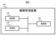
- FIG. 1 is a block diagram showing a configuration of a device management device according to an embodiment of the present disclosure.
- FIG. 1 is a block diagram showing a configuration of a power management device according to an embodiment of the present disclosure.
- FIG. 1 is a block diagram showing a configuration of a power supply and demand adjustment system according to an embodiment of the present disclosure.
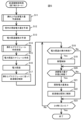
- Flowchart of water heater control process according to an embodiment of the present disclosure.
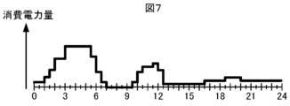
- FIG. 1 is a diagram for explaining a process for predicting the amount of electric power required for boiling according to an embodiment of the present disclosure;
- FIG. 1 is a diagram for explaining a process for predicting the amount of electric power required for boiling according to an embodiment of the present disclosure; FIG.
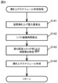
- FIG. 1 is a diagram for explaining a boiling schedule creation process according to an embodiment of the present disclosure.
- FIG. 1 is a diagram for explaining a method for identifying a time period during a shift during which the cost of procuring electricity is the lowest in an embodiment of the present disclosure;
- the power supply and demand adjustment system 1 is a system that adjusts the supply and demand of power to each consumer 800 within the pipe, and includes an equipment management device 100 and a power management device 200. All consumers 800 within the pipe are equipped with a water heater 300, a power meter 400, and a controller 500. Furthermore, some consumers 800 within the pipe are equipped with power generation equipment 600 such as solar panels.
- the water heater 300 is a storage-type water heater equipped with a hot water storage tank and a heat pump.
- the water heater 300 stores water in the hot water storage tank and boils it using the heat pump.
- the hot water storage tank can store several hundred liters of water.
- the water heater 300 consumes a considerable amount of electricity to boil the large amount of water in the hot water storage tank when boiling water, but once the water has been boiled, residents can use the boiled water (hot water).
- the water heater 300 also has a communication function for transmitting the value of the power consumption. For example, the water heater 300 measures the amount of power consumed in each five minutes, and transmits the measured value to the controller 500. Each time the controller 500 receives a value of the amount of power consumed from the water heater 300, it transmits it to the equipment management device 100 via the network 700.
- the power meter 400 is a smart meter that has the function of measuring the power used by the consumer 800 and the communication function of transmitting the measured power value.
- the power used by the consumer 800 includes the power used by the water heater 300, as well as the power used by air conditioners, lighting equipment, cooking appliances, etc. (not shown).
- the power meter 400 measures the amount of power consumed within the consumer 800 during a 30-minute period, for example, every 30 minutes, and transmits the measured value to the controller 500.
- the controller 500 is a control device that complies with the standards for the Home Energy Management System (HEMS) and controls the operation of various electrical appliances in the consumer's facility 800. Every 30 minutes, the controller 500 obtains the value of the amount of power consumed by the consumer's facility 800 from the power meter 400 and transmits it to the power management device 200 via the network 700. The controller 500 also obtains the value of the amount of power consumed by the water heater 300 from the water heater 300 every 5 minutes and transmits it to the equipment management device 100 via the network 700.
- HEMS Home Energy Management System
- Each consumer 800 may be a detached house or a unit in a collective housing complex such as a condominium or apartment.
- each consumer 800 is equipped with a water heater 300, a power meter 400, and a controller 500.
- the equipment management device 100 is a computer for monitoring and controlling the water heaters 300 in the consumer's 800 via the network 700. For example, the equipment management device 100 acquires the power consumption values of the water heaters 300 via the network 700. The equipment management device 100 also controls the water heaters 300 by sending water heating commands to the water heaters 300 via the network 700.
- the device management device 100 includes a control unit 110, a storage unit 120, and a communication unit 130.
- the control unit 110 includes a CPU (Central Processing Unit), a ROM (Read Only Memory), a RAM (Random Access Memory), etc., and controls the device management device 100.
- the storage unit 120 includes non-volatile semiconductor memory such as a flash memory, an EPROM (Erasable Programmable Read Only Memory), and an EEPROM (Electrically Erasable Programmable ROM).
- the storage unit 120 stores programs and data used by the control unit 110 to execute various processes, and stores data generated or acquired by the control unit 110 executing various processes.
- the communication unit 130 has a function of connecting to a network 700, and communicates with each device connected to the network 700 according to the control of the control unit 110.
- the power management device 200 is a computer for monitoring and controlling the power consumption of the consumer 800.
- the power management device 200 acquires the value of the power consumption of the consumer 800 via the network 700.
- the power management device 200 also performs processing to procure the power required by the consumer 800 from the electricity market.
- the power management device 200 comprises a control unit 220, a storage unit 230, and a communication unit 240.
- the control unit 220 comprises a CPU, ROM, RAM, etc., and controls the power management device 200.
- the storage unit 230 comprises non-volatile semiconductor memory such as flash memory, EPROM, and EEPROM.
- the storage unit 230 stores programs and data used by the control unit 220 to execute various processes, and stores data generated or acquired by the control unit 220 executing various processes.
- the communication unit 240 has a function of connecting to a network 700, and communicates with each device connected to the network 700 according to the control of the control unit 220.
- FIG. 4 shows the functional configuration of the power supply and demand adjustment system 1.
- the equipment management device 100 includes a water heater power collection unit 101, a water heater power history storage unit 102, a water heater power amount prediction unit 103, a water heater planning unit 104, a water heater schedule 105, a water heater control unit 106, a water heater adjustment unit 107, and a water heater specific information storage unit 108.
- the water heater power collection unit 101 obtains the power consumption value of each water heater 300 from each controller 500 in the pipe every five minutes, and accumulates and stores the results to date in the water heater power history storage unit 102.
- the water heater power history storage unit 102 stores the actual power consumption values of each water heater 300 collected by the water heater power collection unit 101 for the past 14 days.
- the water boiling power prediction unit 103 predicts the amount of power required for water boiling in the future (for the next day) from the actual values of the power amounts of the water heater 300 in the past stored in the water heater power history storage unit 102.
- the amount of power predicted by the water boiling power prediction unit 103 is also referred to as the amount of power required for water boiling.
- the water heater planning unit 104 determines an operation plan for the water heater 300 so as to reduce the power procurement cost. Specifically, the water heater planning unit 104 determines a water heater shift destination period for which the power procurement cost will be the lowest based on the power procurement price predicted by the power procurement price prediction unit 205 described below and the unique information about each water heater 300 stored in the water heater specific information storage unit 108 described below, and creates a water heater schedule 105 that shifts at least a portion of the amount of power required for water heater to the water heater shift destination period.
- the water heater control unit 106 controls each water heater 300 in the pipe according to the water heating schedule 105 created by the water heating planning unit 104.
- the water heater adjustment unit 107 identifies the water heater 300 that can increase or decrease the amount of power equivalent to the adjustment power amount calculated by the adjustment command unit 210 described below, and commands the identified water heater 300 to perform a water heater operation that differs from the operation according to the water heater schedule 105 by the water heater control unit 106.
- the water heater specific information storage unit 108 stores information specific to each water heater 300 in the pipe. Specifically, the water heater specific information storage unit 108 stores information indicating the rated power consumption, maximum hot water storage amount, current hot water amount, heating capacity, heat retention efficiency, etc. of each water heater 300.
- the rated power consumption of a water heater 300 is the power consumption when the water heater 300 is operated at maximum output, and corresponds to the maximum power consumption of the water heater 300.
- the power management device 200 includes a power collection unit 201, a power history storage unit 202, a power demand forecasting unit 203, a power procurement price actual performance storage unit 204, a power procurement price forecasting unit 205, a power procurement planning unit 206, a power procurement schedule 207, a power procurement unit 208, a power generation control unit 209, and an adjustment command unit 210.
- the power collection unit 201 obtains the power consumption values of each consumer 800 within the area from each controller 500 of the consumer 800 every 30 minutes, and stores the values in the power history storage unit 202 as past performance data.
- the power history storage unit 202 stores the actual power consumption values of each consumer 800 collected by the power collection unit 201 for the past 14 days.
- the power demand forecasting unit 203 forecasts the amount of power demand for all consumers 800 in the area for a certain period of time in the future (the next day) based on the actual power consumption values of each consumer 800 stored in the power history storage unit 202.
- the actual power procurement price memory unit 204 stores the actual procurement price of power procured in the past.
- the procurement price is expressed, for example, as the amount required to procure a unit amount of power.
- the power procurement price prediction unit 205 predicts the power procurement price every 30 minutes in the jurisdiction for the next day based on the actual procurement price values stored in the power procurement price actual result storage unit 204.
- the power procurement planning unit 206 determines the amount of power required to be procured within the jurisdiction for each fixed time period on the following day based on the amount of demanded power predicted by the power demand forecasting unit 203 and the power boiling amount plan for each fixed time period (power boiling schedule 105) drawn up by the power boiling planning unit 104, and creates a power procurement schedule 207.
- the power procurement unit 208 procures the required amount of power from the power market or the power generation facility 600 based on the power procurement schedule 207.
- the power generation control unit 209 is connected to the power generation equipment 600 in the area, and controls the power generation equipment 600 so that it generates at least the required amount of electricity to be procured from the power generation equipment 600.
- the adjustment command unit 210 calculates the amount of adjustment power to make up for the discrepancy.
- the water heater control process executed by the power supply and demand adjustment system 1 will be described.
- the water heater power collection unit 101 of the equipment management device 100 always executes a process in parallel whereby the water heater 300's power consumption amount is collected every 5 minutes and stored in the water heater power history storage unit 102, and the power collection unit 201 of the power management device 200 always executes a process in parallel whereby the power collection unit 201 of the power management device 200 collects the power consumption amount of the consumer 800 every 30 minutes and stores it in the power history storage unit 202.
- the water heater control process shown in FIG. 5 is executed every day at 7:00 a.m.
- the water heater power prediction unit 103 of the equipment management device 100 executes a water heater power requirement prediction process to predict the amount of power required for water heater heating for the next day from the actual values of the power usage of each water heater 300 in the past stored in the water heater power history storage unit 102 (step S11).
- the details of the water heater power requirement prediction process will be explained using the flowchart in FIG. 6.
- the water boiling power prediction unit 103 calculates the average power consumption for each 30 minutes in one day for all water heaters 300 in the pipe from the power consumption history of each water heater 300 in the pipe for the last 14 days stored in the water heater power history storage unit 102 (step S111).
- the average power consumption per 30 minutes calculated in step S111 includes the amount of water heating shifted to the daytime hours (9:00 to 19:00). Therefore, the water heating power prediction unit 103 shifts the average power consumption calculated in step S111 for the daytime hours to the late-night hours (0:00 to 6:00) (step S112). If it is a late-night hour, the shift can be made arbitrarily, but it should not exceed the upper limit of the power consumption per 30 minutes for the entire water heater 300. The upper limit of the power consumption per 30 minutes for the entire water heater 300 can be found from the rated power consumption of each water heater 300 stored in the water heater specific information storage unit 108.
- the boiling power prediction unit 103 may hold the average value of the rated power consumption of each water heater 300, and calculate the upper limit of the power consumption per 30 minutes for each water heater 300 from this average value, and add these values together for the number of water heaters 300 in the pipe to calculate the upper limit of the power consumption per 30 minutes for all water heaters 300.
- step S111 For example, consider a case where the average power consumption of the entire water heater 300 is calculated in step S111 as shown in FIG. 7.
- step S112 as shown in FIG. 8, part A of the average power consumption during the daytime hours is shifted to part B of the average power consumption during the nighttime hours within a range that does not exceed the upper limit value Z of the power consumption per 30 minutes described above.
- the water boiling power prediction unit 103 then calculates the amount of power required for water boiling for the entire water heater 300 for one day from the average power consumption of the entire water heater 300 that was shifted in step S112 (step S113). Note that the amount of power required for water boiling for one day may also be calculated from the average power consumption of the entire water heater 300 that is not shifted in step S112. This ends the process of predicting the amount of power required for water boiling.
- the power demand prediction unit 203 of the power management device 200 predicts the amount of power demand for all of the consumers 800 in the area for a certain period of time (every 30 minutes) in the future (next day) (step S12). Specifically, the power demand prediction unit 203 may predict the amount of power demand by averaging the actual values of the power consumption of each consumer 800 stored in the power history storage unit 202. Note that at this time, it is preferable for the power demand prediction unit 203 to predict the amount of power demand in the case where the water heater 300 does not shift the water heating to the daytime hours.
- the power demand prediction unit 203 performs a process of returning the daytime water heating shift to the nighttime hours (a process of returning to a state where no shift was performed) as described in FIG. 8, and then predicts the amount of power demand for all of the consumers 800 for a certain period of time (every 30 minutes) in the future (next day).
- the power procurement price prediction unit 205 of the power management device 200 predicts the power procurement price for every 30 minutes in the jurisdiction on the following day based on the actual power procurement price values stored in the power procurement price actual value storage unit 204 (step S13).
- the water heating planning unit 104 of the equipment management device 100 executes a water heating schedule creation process to create a water heating schedule 105 for the water heater 300 so as to reduce the power procurement cost based on the power procurement price predicted in step S13 (step S14).
- the details of the water heating schedule creation process will be described with reference to FIG. 9.
- the water heating planning unit 104 first calculates the amount of electricity (daytime water heating electricity amount) that will be shifted from nighttime (12:00-6:00) to daytime (9:00-19:00) for the entire water heater 300 (step S141).
- each water heater 300 in the pipe predicts the daytime heating power amount to be shifted from nighttime to daytime at the time (for example, around 11:00 p.m.) just before nighttime heating starts every day, and performs heating operation according to the prediction. For example, each water heater 300 calculates the amount of power required for heating for one day at 11:00 p.m. based on the hot water usage record for a certain period in the past, for example the last two weeks, the remaining amount in the tank, etc., and predicts the daytime heating power amount as a part of that, for example 30%, to be shifted to daytime.
- the heating planning unit 104 can obtain the predicted value of the daytime heating power amount most recently predicted by the water heater 300 from each water heater 300 in the pipe, and calculate the daytime heating power amount for the entire water heater 300 by adding them up.
- the water heating planning unit 104 may calculate the daytime water heating power consumption of the entire water heaters 300 from the average value of the predicted daytime water heating power consumption values predicted by each water heater 300 in the pipe for the most recent predetermined number of days (e.g., 14 days).
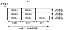
- the water heating planning unit 104 calculates the duration of the shift destination period for the daytime water heating shift (shift duration) (step S142). Specifically, as shown in FIG. 10, the water heating planning unit 104 allocates the daytime water heating power amount calculated in step S141 to each water heater 300 (water heaters A to C) in the pipe in sequence every 30 minutes, in units of the upper limit of the power consumption per 30 minutes. Therefore, in this figure, the height of each rectangle whose area represents the power consumption of water heaters A to C represents the upper limit of the power consumption (rated power consumption) of water heaters A to C. Then, the water heating planning unit 104 calculates the shift duration as the time equivalent to the number of 30-minute frames when all the daytime water heating power amount is allocated. That is, in FIG. 10, the shift duration is calculated to be 90 minutes.
- the boiling water planning unit 104 identifies a time period during the daytime (9:00-17:00) with a shift duration that will result in the lowest electricity procurement cost (step S143). For example, if the shift duration predicted in step S13 is 90 minutes, the boiling water planning unit 104 can identify a time period with the lowest electricity procurement cost from among time periods t1-t14 by shifting the 90-minute shift duration time periods by 30 minutes each time, such as time period t1 from 9:00 to 10:30, time period t2 from 9:30 to 11:00, ..., time period t14 from 15:30 to 17:00, as shown in FIG. 11, within the range from 9:00 to 17:00, and referring to the predicted procurement price each time.
- the water heating planning unit 104 creates a water heating schedule 105 for heating each water heater 300 during the time period of the shift duration identified in step S143 (step S144). This ends the water heating schedule creation process.
- the power procurement planning unit 206 of the power management device 200 determines the amount of power required to be procured within the pipeline at fixed intervals (every 30 minutes) on the following day based on the amount of power demand within the pipeline predicted in step S12 and the boiling schedule 105 created by the boiling planning unit 104, and creates a power procurement schedule 207 (step S15).
- the power procurement unit 208 performs processing (e.g., bidding on the power market) to procure the required amount of power from the power market or from power generation facilities 600 within its jurisdiction in accordance with the created power procurement schedule 207 (step S16).
- processing e.g., bidding on the power market
- the water heater control unit 106 starts controlling the hot water supply of each water heater 300 in the pipe by, for example, registering the boiling schedule 105 created in step S14 in a schedule management tool (step S17). As a result, each water heater 300 performs the hot water supply process at the time specified in the boiling schedule 105.
- the power generation control unit 209 controls the power generation equipment 600 in the area to generate at least the amount of power required to be procured from the power generation equipment 600 (step S19).
- the adjustment command unit 210 calculates the amount of adjustment power to make up for the difference (step S21).
- the boiling adjustment unit 107 of the equipment management device 100 identifies the water heaters 300 that can make up for the calculated amount of regulated power, and controls the identified water heaters 300 individually (step S22). For example, the boiling adjustment unit 107 appropriately transmits power reduction commands, power increase commands, etc. to the identified water heaters 300 that are in boiling operation or scheduled to boil within 30 minutes, depending on the amount of regulated power, to control the operation of the water heaters 300.
- Step S23; Yes the water heater control process ends. If the date has not changed (Step S23; No), the process returns to Step S18.
- the water heating shift destination period that will result in the lowest electricity procurement costs is determined based on the predicted electricity procurement price at each fixed time period, and the water heating of each water heater 300 in the pipe is controlled during the shift destination period, making it possible to further reduce the electricity procurement costs of the electric power company.
- step S142 of the water heating schedule creation process the shift duration was calculated by allocating the daytime water heating power amount to each water heater 300 in increments of the upper limit of power consumption every 30 minutes (FIG. 10), but the method of calculating the shift duration is not limited to this.
- the water heating planning unit 104 may determine the shift duration as the time required for all water heaters 300 to complete heating when multiple water heaters 300 in a pipe start heating at the same time.
- one water heating shift destination period is determined, and the water heater 300 is controlled to heat water during that water heating shift destination period.
- the power supply and demand adjustment system 1 may be configured by a single device that integrates the functions of the equipment management device 100 and the power management device 200.
- a program executed by such a single device to an existing computer, it is possible to cause the computer to function as the power supply and demand adjustment system 1 according to the present disclosure.
- Such programs may be distributed in any manner, for example, by storing them on a computer-readable recording medium such as a CD-ROM (Compact Disk Read-Only Memory), a DVD (Digital Versatile Disk), an MO (Magneto Optical Disk), or a memory card, or by distributing them via a communications network such as the Internet.
- a computer-readable recording medium such as a CD-ROM (Compact Disk Read-Only Memory), a DVD (Digital Versatile Disk), an MO (Magneto Optical Disk), or a memory card, or by distributing them via a communications network such as the Internet.
- Power supply and demand adjustment system 100.
- Equipment management device 200.
- Power management device 300.
- Water heater 400.
- Power meter 500. Controller, 600.
- Power generation equipment 700.
- Network 800.
- Consumer 101.
- Water heater power collection unit 102.
- Water heater power history memory unit 103.
- Water heating power forecast unit 104.
- Water heating planning unit 105.
- Water heating schedule 106.
- Water heater control unit 107.
- Boiling adjustment unit 108 Water heater specific information storage unit, 110, 220 Control unit, 120, 230 Storage unit, 130, 240 Communication unit, 201 Power collection unit, 202 Power history storage unit, 203 Power demand forecast unit, 204 Power procurement price actual storage unit, 205 Power procurement price forecast unit, 206 Power procurement planning unit, 207 Power procurement schedule, 208 Power procurement unit, 209 Power generation control unit, 210 Coordination command unit
Landscapes
- Engineering & Computer Science (AREA)
- Physics & Mathematics (AREA)
- Thermal Sciences (AREA)
- Chemical & Material Sciences (AREA)
- Combustion & Propulsion (AREA)
- Mechanical Engineering (AREA)
- General Engineering & Computer Science (AREA)
- Management, Administration, Business Operations System, And Electronic Commerce (AREA)
- Heat-Pump Type And Storage Water Heaters (AREA)
Abstract
管内の給湯機(300)を備える需要家への電力需給を調整する電力需給調整システム(1)は、給湯機(300)の消費電力量実績から未来の沸き上げ必要電力量を予測する沸き上げ電力量予測部(103)と、電力調達価格実績に基づき、未来の一定時間毎の電力調達価格を予測する電力調達価格予測部(205)と、電力調達価格予測部(205)が予測した電力調達価格に基づいて、最も電力調達コストが小さくなる沸き上げシフト先期間を決定し、沸き上げ必要電力量の少なくとも一部を沸き上げシフト先期間で消費する沸き上げスケジュール(105)を計画する沸き上げ計画部(104)と、沸き上げスケジュール(105)に従って、管内の給湯機(300)を制御する給湯機制御部(106)と、を備える。
Description
本開示は、電力需給調整システム、電力需給調整方法、及び、プログラムに関する。
電力事業者が需要家に供給する電力を調達するコストを低減するための種々の技術が知られている。例えば、特許文献1には、各電力需要者の需要予測量、電力取引情報、履歴などに基づいたポジションで入札をして電力卸市場から電力を調達し、翌日の発電計画・需給計画を生成する電力需要調達支援サーバについて記載されている。
需要家には、貯湯式の給湯機を有している場合も多い。このような需要家の場合、給湯機の沸き上げ時間を工夫することで電力調達コストをさらに低減することが期待できる。引用文献1に記載の技術では、給湯機を管理するようなことについては記載がないため、このような効果を得ることはできない。
本開示は、上記実情に鑑みてなされたものであり、電力事業者の電力調達コストをより低減することができる電力需給調整システムなどを提供することを目的とする。
上記目的を達成するため、本開示に係る電力需給調整システムは、
管内の給湯機を備える需要家への電力需給を調整する電力需給調整システムであって、
前記給湯機の消費電力量実績から未来の沸き上げ必要電力量を予測する沸き上げ電力量予測部と、
電力調達価格実績に基づき、未来の一定時間毎の電力調達価格を予測する電力調達価格予測部と、
前記電力調達価格予測部が予測した前記電力調達価格に基づいて、最も電力調達コストが小さくなる沸き上げシフト先期間を決定し、前記沸き上げ必要電力量の少なくとも一部を前記沸き上げシフト先期間で消費する沸き上げスケジュールを作成する沸き上げ計画部と、
前記沸き上げスケジュールに従って、前記管内の前記給湯機を制御する給湯機制御部と、
を備える。
管内の給湯機を備える需要家への電力需給を調整する電力需給調整システムであって、
前記給湯機の消費電力量実績から未来の沸き上げ必要電力量を予測する沸き上げ電力量予測部と、
電力調達価格実績に基づき、未来の一定時間毎の電力調達価格を予測する電力調達価格予測部と、
前記電力調達価格予測部が予測した前記電力調達価格に基づいて、最も電力調達コストが小さくなる沸き上げシフト先期間を決定し、前記沸き上げ必要電力量の少なくとも一部を前記沸き上げシフト先期間で消費する沸き上げスケジュールを作成する沸き上げ計画部と、
前記沸き上げスケジュールに従って、前記管内の前記給湯機を制御する給湯機制御部と、
を備える。
本開示によれば、電力事業者の電力調達コストをより低減することが可能となる。
以下、本開示の実施形態について、図面を参照しながら詳細に説明する。なお、図中同一または相当部分には同一符号を付す。
本開示の実施形態に係る電力需給調整システム1について説明する。電力需給調整システム1の構成を図1に示す。電力需給調整システム1は、管内の各需要家800への電力需給を調整するシステムであり、機器管理装置100と電力管理装置200とを備える。管内の全ての需要家800は、給湯機300と、電力測定器400と、コントローラ500と、を備えている。さらに、いくつかの管内の需要家800は、太陽光パネルなどの発電設備600を備えているものもある。
給湯機300は、貯湯タンク及びヒートポンプを備える貯湯式の給湯機である。給湯機300は、水を貯湯タンクに貯め、それをヒートポンプで沸き上げる。貯湯タンクには数百リットルの水を蓄えることができる。給湯機300は、沸き上げ時に貯湯タンク内の大量の水を沸き上げるため、かなりの電力を消費するが、一度沸き上げてしまえば、その後、住人は沸き上げた水(お湯)を用いることができる。
また、給湯機300は消費した電力の値を送信する通信機能を備えている。給湯機300は、例えば5分毎にその5分で消費した電力量を測定し、測定値をコントローラ500に送信している。コントローラ500は、給湯機300から電力量の値を受信する毎に、ネットワーク700を介して、機器管理装置100に送信している。
電力測定器400は、需要家800で使用される電力を測定する機能と、測定した電力の値を送信する通信機能とを備えるスマートメータである。需要家800で使用される電力には、給湯機300が使用する電力も含まれるし、図示せぬ空調機、照明機器、調理家電機器等が使用する電力も含まれる。電力測定器400は、例えば30分毎にその30分間に需要家800内で消費された電力量を測定し、測定値をコントローラ500に送信している。
コントローラ500は、HEMS(Home Energy Management System)の規格に準拠した制御装置であり、需要家800内の各種電気機器の運転を制御する。コントローラ500は、30分毎に、需要家800で消費される電力量の値を電力測定器400から取得し、ネットワーク700を介して電力管理装置200に送信する。また、コントローラ500は、5分毎に、給湯機300で消費される電力量の値を給湯機300から取得し、ネットワーク700を介して機器管理装置100に送信する。
需要家800は、それぞれ一戸建ての住宅でも良いし、マンション、アパートといった集合住宅の中の一つの住戸でも良い。本実施の形態においてはどの需要家800も給湯機300、電力測定器400、コントローラ500を備えている。
機器管理装置100は、ネットワーク700を介して、需要家800内の給湯機300を監視、制御するためのコンピュータである。例えば、機器管理装置100は、ネットワーク700を介して、給湯機300の消費電力量の値を取得する。また、機器管理装置100は、ネットワーク700を介して、各給湯機300に対し、沸き上げ指令を送信することにより、各給湯機300の沸き上げ制御を行う。
機器管理装置100は、図2に示すように、制御部110と、記憶部120と、通信部130とを備える。制御部110は、CPU(Central Processing Unit)、ROM(Read Only Memory)、RAM(Random Access Memory)等を備え、機器管理装置100を統括制御する。記憶部120は、フラッシュメモリ、EPROM(Erasable Programmable Read Only Memory)、EEPROM(Electrically Erasable Programmable ROM)等の不揮発性の半導体メモリを備える。記憶部120は、制御部110が各種処理を実行するために使用するプログラム及びデータを記憶したり、制御部110が各種処理を実行することにより生成又は取得するデータを記憶したりする。通信部130は、ネットワーク700に接続する機能を有し、制御部110の制御に従って、ネットワーク700に接続された各機器と通信する。
図1に戻り、電力管理装置200は、需要家800の消費電力を監視、制御するためのコンピュータである。例えば、電力管理装置200は、ネットワーク700を介して、需要家800の消費電力量の値を取得する。また、電力管理装置200は、電力市場から需要家800で必要な電力を調達するための処理を行う。
電力管理装置200は、図3に示すように、制御部220と、記憶部230と、通信部240とを備える。制御部220は、CPU、ROM、RAM等を備え、電力管理装置200を統括制御する。記憶部230は、フラッシュメモリ、EPROM、EEPROM等の不揮発性の半導体メモリを備える。記憶部230は、制御部220が各種処理を実行するために使用するプログラム及びデータを記憶したり、制御部220が各種処理を実行することにより生成又は取得するデータを記憶したりする。通信部240は、ネットワーク700に接続する機能を有し、制御部220の制御に従って、ネットワーク700に接続された各機器と通信する。
ここで、図4は、電力需給調整システム1の機能的構成を示したものである。機器管理装置100は、給湯機電力収集部101と、給湯機電力履歴記憶部102と、沸き上げ電力量予測部103と、沸き上げ計画部104と、沸き上げスケジュール105と、給湯機制御部106と、沸き上げ調整部107と、給湯機固有情報記憶部108と、を備える。
給湯機電力収集部101は、5分毎に、管内の各コントローラ500から各給湯機300の消費電力量の値を取得し、給湯機電力履歴記憶部102にこれまでの実績として蓄積記憶する。
給湯機電力履歴記憶部102には、給湯機電力収集部101が収集した各給湯機300の電力量の実績値が直近14日間分記憶される。
沸き上げ電力量予測部103は、給湯機電力履歴記憶部102に記憶されている過去の給湯機300の電力量の実績値から、未来(翌日1日分)の沸き上げに必要な電力量を予測する。以下の説明では、沸き上げ電力量予測部103が予測した電力量を沸き上げ必要電力量とも表記する。
沸き上げ計画部104は、電力調達コストが小さくなるように給湯機300の運転計画を決定する。具体的には、沸き上げ計画部104は、後述する電力調達価格予測部205が予測した電力調達価格と後述する給湯機固有情報記憶部108に記憶されている各給湯機300に関する固有の情報とに基づいて、最も電力調達コストが小さくなる沸き上げシフト先期間を決定し、沸き上げ必要電力量の少なくとも一部を沸き上げシフト先期間にシフトする沸き上げスケジュール105を作成する。
給湯機制御部106は、沸き上げ計画部104が作成した沸き上げスケジュール105に従って、管内の各給湯機300を制御する。
沸き上げ調整部107は、後述する調整指令部210が算出した調整電力量に相当する電力量を増減することが可能な給湯機300を特定し、特定した給湯機300に、給湯機制御部106による沸き上げスケジュール105に従った運転とは異なる沸き上げ運転をするよう指令する。
給湯機固有情報記憶部108には、管内の各給湯機300に固有の情報を記憶する。具体的には、給湯機固有情報記憶部108には、各給湯機300の定格消費電力、最大貯湯量、現在の湯量、加熱能力、保温効率等を示す情報が記憶されている。なお、給湯機300の定格消費電力は、その給湯機300を最大出力で運転させたときの消費電力であり、その給湯機300における消費電力の最大値に相当する。
電力管理装置200は、電力収集部201と、電力履歴記憶部202と、電力需要予測部203と、電力調達価格実績記憶部204と、電力調達価格予測部205と、電力調達計画部206と、電力調達スケジュール207と、電力調達部208と、発電制御部209と、調整指令部210と、を備える。
電力収集部201は、30分毎に、管内の需要家800の各コントローラ500から各需要家800の消費電力量の値を取得し、電力履歴記憶部202にこれまでの実績として記憶する。
電力履歴記憶部202には、電力収集部201が収集した各需要家800の電力量の実績値が直近14日間分記憶される。
電力需要予測部203は、電力履歴記憶部202に記憶されている各需要家800の消費電力量の実績値に基づいて、管内の需要家800全体での未来(翌日)の一定期間毎の需要電力量を予測する。
電力調達価格実績記憶部204には、過去に調達した電力の調達価格の実績値が記憶されている。調達価格は、例えば、単位電力量当たりの調達に要する金額で表される。
電力調達価格予測部205は、電力調達価格実績記憶部204に記憶されている調達価格の実績値に基づいて、管内における翌日1日における30分毎の電力調達価格を予測する。
電力調達計画部206は、電力需要予測部203が予測した需要電力量と沸き上げ計画部104が立案した一定時間毎の沸き上げ電力量計画(沸き上げスケジュール105)とに基づき、管内の翌日の一定時間毎の調達必要電力量を決定して電力調達スケジュール207を作成する。
電力調達部208は、電力調達スケジュール207に基づいて、調達必要電力量を電力市場または発電設備600から調達する。
発電制御部209は、管内の発電設備600に接続されており、当該発電設備600から調達する分の調達必要電力量を少なくとも発電するように当該発電設備600を制御する。
調整指令部210は、管内の消費電力量実績と、調達必要電力量とに差異が生ずる場合に、当該差異分を埋め合わせるための調整電力量を算出する。
続いて、電力需給調整システム1が実行する給湯機制御処理について説明する。電力需給調整システム1は、常に、機器管理装置100の給湯機電力収集部101が5分毎に給湯機300の消費電力量を収集して給湯機電力履歴記憶部102に記憶する処理、および、電力管理装置200の電力収集部201が30分毎に需要家800の消費電力量を収集して電力履歴記憶部202に記憶する処理が並行して実行されている。そして、これらの処理とは別スレッドで並行して、図5に示す給湯機制御処理が毎日朝7時に実行される。
給湯機制御処理が開始されると、まず、機器管理装置100の沸き上げ電力量予測部103は、給湯機電力履歴記憶部102に記憶されている過去の各給湯機300の電力量の実績値から、翌日1日分の沸き上げ必要電力量を予測する沸き上げ必要電力量予測処理を実行する(ステップS11)。沸き上げ必要電力量予測処理の詳細について、図6のフローチャートを用いて説明する。
まず、沸き上げ電力量予測部103は、給湯機電力履歴記憶部102に記憶されている直近14日分の管内の各給湯機300の電力量の履歴から、管内の給湯機300全体の1日における、30分毎の平均消費電力量を算出する(ステップS111)。
ステップS111で算出した30分毎の平均消費電力量には、昼間の時間帯(9時~19時)にシフトして沸き上げをした分が含まれている。そのため、沸き上げ電力量予測部103は、ステップS111で算出した平均消費電力量のうち、昼間の時間帯の平均消費電力量を深夜の時間帯(0時~6時)にシフトする(ステップS112)。深夜時間帯であればどのようにシフトするかは任意であるが、給湯機300全体の30分当たりの消費電力量の上限値を超えないようにする。ここでの給湯機300全体の30分当たりの消費電力量の上限値は、給湯機固有情報記憶部108に記憶されている各給湯機300の定格消費電力から求めることができる。例えば、管内に定格消費電力が1kWの給湯機300が5台、2kWの給湯機300が5台あるとすると、30分当たりの消費電力量の上限値は7.5kWhとなる。なお、沸き上げ電力量予測部103は、各給湯機300の定格消費電力の平均値を保有しておき、この平均値から1台の給湯機300の30分当たりの消費電力量の上限値を求め、これらを管内の給湯機300の台数分足し合わせることにより、給湯機300全体の30分当たりの消費電力量の上限値を求めてもよい
例えば、ステップS111で図7に示すように給湯機300全体の平均消費電力量が算出された場合を考える。この場合、ステップS112において、図8に示すように、上述した30分当たりの消費電力量の上限値Zを越えない範囲で、昼間の時間帯の平均消費電力量の部分Aが、夜間時間帯の部分Bにシフトされる。
図6に戻り、続いて、沸き上げ電力量予測部103は、ステップS112でシフトされた給湯機300全体の平均消費電力量から給湯機300全体の1日分の沸き上げ必要電力量を算出する(ステップS113)。なお、ステップS112のシフトをしない給湯機300全体の平均消費電力量から1日分の沸き上げ必要電力量を算出してもよい。以上で沸き上げ必要電力量予測処理は終了する。
図5に戻り、沸き上げ必要電力量予測処理が終了すると、電力管理装置200の電力需要予測部203は、管内の需要家800全体での未来(翌日)の一定期間毎(30分毎)の需要電力量を予測する(ステップS12)。具体的には、電力需要予測部203は、電力履歴記憶部202に記憶されている各需要家800の消費電力量の実績値を平均化することで需要電力量を予測すればよい。なお、このとき電力需要予測部203は、給湯機300の沸き上げを昼間の時間帯にシフトしない場合の需要電力量を予測するのが望ましい。即ち、電力需要予測部203は、図8で説明したような、昼間の時間帯の沸き上げシフトを深夜時間帯に戻す処理(シフトを行わなかった状態に戻す処理)を行った上で、需要家800全体での未来(翌日)の一定期間毎(30分毎)の需要電力量を予測する。
続いて、電力管理装置200の電力調達価格予測部205は、電力調達価格実績記憶部204に記憶されている電力調達価格の実績値に基づいて、管内における翌日1日における30分毎の電力調達価格を予測する(ステップS13)。
続いて、機器管理装置100の沸き上げ計画部104は、ステップS13で予測した電力調達価格に基づいて、電力調達コストが小さくなるように給湯機300の沸き上げスケジュール105を作成する沸き上げスケジュール作成処理を実行する(ステップS14)。沸き上げスケジュール作成処理の詳細について図9を用いて説明する。
沸き上げスケジュール作成処理が開始されると、まず、沸き上げ計画部104は、給湯機300全体での夜間(0時~6時)から昼間(9時~19時)に沸き上げシフトする電力量(昼間沸き上げ電力量)を算出する(ステップS141)。
ここで、昼間沸き上げ電力量の算出について具体的に説明する。管内の各給湯機300は、基本的に、毎日、夜間沸き上げを開始する直前の時刻(例えば、23時頃)に、夜間から昼間にシフトする昼間沸き上げ電力量を予測し、予測に従って沸き上げ運転を行っている。例えば、各給湯機300は、23時に、過去の一定期間、例えば直近2週間の湯の使用実績、タンクの残量等から、沸き上げに必要な1日分の必要電力量を算出し、そのうちの一部、例えば30%を昼間にシフトする分として昼間沸き上げ電力量を予測している。なお、各給湯機300による昼間沸き上げ電力量の予測方法は種々の方法が考えられ、これに限定されるものではない。そのため、沸き上げ計画部104は、管内の各給湯機300から、給湯機300が直近に予測した昼間沸き上げ電力量の予測値を取得し、それらを合計することで、給湯機300全体での昼間沸き上げ電力量を算出することができる。なお、沸き上げ計画部104は、直近の予め定めた日数分(例えば、14日分)の管内の各給湯機300が予測した昼間沸き上げ電力量の予測値の平均値から、給湯機300全体での昼間沸き上げ電力量を算出してもよい。
続いて、沸き上げ計画部104は、昼間沸き上げシフトするシフト先期間の継続時間(シフト継続時間)を算出する(ステップS142)。具体的には、沸き上げ計画部104は、図10に示すように、ステップS141で算出した昼間沸き上げ電力量を、30分毎に管内の各給湯機300(給湯機A~C)に、30分当たりの消費電力量の上限分ずつ順に割り振っていく。従って、この図において、面積が給湯機A~Cの消費電力量を表す各矩形の高さは、給湯機A~Cの消費電力の上限(定格消費電力)を表す。そして、沸き上げ計画部104は、昼間沸き上げ電力量を全て割り振った場合の30分のコマ数に相当する時間をシフト継続時間として算出する。即ち、図10では、シフト継続時間は90分と算出される。
続いて、沸き上げ計画部104は、ステップS13で予測した電力の調達価格に基づいて、昼間の時間帯(9時~17時)の中から、最も電力の調達コストが安くなるシフト継続時間の時間帯を特定する(ステップS143)。例えば、ステップS13で予測したシフト継続時間を90分とすると、沸き上げ計画部104は、図11に示すように、9時~17時の範囲で、9時~10時30分の時間帯t1、9時30分~11時の時間帯t2、・・・、15時30分~17時の時間帯t14のように、30分ずつシフト継続時間である90分の長さの時間帯をずらしながら、都度、予測した調達価格を参照していくことによって、時間帯t1~t14の中から電力調達コストが最小となる時間帯を特定することができる。
続いて、沸き上げ計画部104は、ステップS143で特定したシフト継続時間の時間帯に各給湯機300の沸き上げをする沸き上げスケジュール105を作成する(ステップS144)。以上で沸き上げスケジュール作成処理は終了する。
図5に戻り、沸き上げスケジュール作成処理が終了すると、電力管理装置200の電力調達計画部206は、ステップS12で予測した管内の需要電力量と沸き上げ計画部104が作成した沸き上げスケジュール105とに基づき、管内の翌日の一定時間毎(30分毎)の調達必要電力量を決定して、電力調達スケジュール207を作成する(ステップS15)。
そして、電力調達部208は、作成した電力調達スケジュール207に従い、調達必要電力量を電力市場または管内の発電設備600から調達するための処理(例えば、電力市場への入札)を行う(ステップS16)。
続いて、給湯機制御部106は、ステップS14で作成された沸き上げスケジュール105をスケジュール管理ツールに登録するなどして、管内の各給湯機300の給湯制御を開始する(ステップS17)。これにより、各給湯機300では、沸き上げスケジュール105で規定された時間に湯上げの処理が行われる。
続いて、電力調達スケジュール207で規定された電力調達の実行時刻になると(ステップS18;Yes)、発電制御部209は、管内の発電設備600から調達する分の調達必要電力量を少なくとも発電するように当該発電設備600を制御する(ステップS19)。
また、電力履歴記憶部202で随時更新される管内の消費電力量の実績値と調達必要電力量とに予め定めた基準以上の差異が生じる場合(ステップS20;Yes)、調整指令部210は、当該差異分を埋め合わせるための調整電力量を算出する(ステップS21)。
そして、機器管理装置100の沸き上げ調整部107は、算出した調整電力量を埋め合わせることが可能な給湯機300を特定し、特定した給湯機300を個別に制御する(ステップS22)。例えば、沸き上げ調整部107は、調整電力量に応じて、特定した沸き上げ運転中又は30分以内に沸き上げ予定のある給湯機300に、電力削減指令、電力増加指令等を適宜送信して、当該給湯機300の運転を制御する。
そして、24時になり日付が変わったタイミングで(ステップS23;Yes)、給湯機制御処理は終了する。また、日付が変わっていない場合は(ステップS23;No)、処理はステップS18に戻る。
このように本開示によれば、予測された一定時間毎の電力調達価格に基づいて、最も電力調達コストが小さくなる沸き上げシフト先期間が決定され、シフト先期間に管内の各給湯機300の沸き上げが制御されるため、電力事業者の電力調達コストをより低減することが可能となる。
(変形例)
なお、本開示は、上記実施形態に限定されず、本開示の要旨を逸脱しない範囲での種々の変更は勿論可能である。
なお、本開示は、上記実施形態に限定されず、本開示の要旨を逸脱しない範囲での種々の変更は勿論可能である。
沸き上げスケジュール作成処理のステップS142において、30分毎に昼間沸き上げ電力量を消費電力量の上限分ずつ各給湯機300に割り振っていくことによってシフト継続時間を算出したが(図10)、シフト継続時間の算出方法はこれに限定されるものではない。例えば、沸き上げ計画部104は、菅内にある複数の給湯機300を同時に沸き上げ開始した場合に、複数の給湯機300の全ての沸き上げが完了するまでに必要な時間をシフト継続時間としてもよい。
上記実施の形態では、1つの沸き上げシフト先期間を決定して、当該沸き上げシフト先期間に沸き上げするように給湯機300を制御したが、決定した1つの沸き上げシフト先期間を分割するなどして複数の沸き上げシフト先期間を決定して、それぞれの沸き上げシフト先期間に沸き上げをするように給湯機300を制御してもよい。
例えば、機器管理装置100と電力管理装置200の機能が統合された1つの装置によって、電力需給調整システム1を構成してもよい。また、このような1つの装置が実行するプログラムを、既存のコンピュータに適用することで、当該コンピュータを本開示に係る電力需給調整システム1として機能させることも可能である。
このようなプログラムの配布方法は任意であり、例えば、CD-ROM(Compact Disk Read-Only Memory)、DVD(Digital Versatile Disk)、MO(Magneto Optical Disk)、メモリカード等のコンピュータ読み取り可能な記録媒体に格納して配布してもよいし、インターネット等の通信ネットワークを介して配布してもよい。
本開示は、本開示の広義の精神と範囲を逸脱することなく、様々な実施形態及び変形が可能とされるものである。また、上述した実施形態は、本開示を説明するためのものであり、本開示の範囲を限定するものではない。つまり、本開示の範囲は、実施形態ではなく、請求の範囲によって示される。そして、請求の範囲内及びそれと同等の開示の意義の範囲内で施される様々な変形が、本開示の範囲内とみなされる。
1 電力需給調整システム、100 機器管理装置、200 電力管理装置、300 給湯機、400 電力測定器、500 コントローラ、600 発電設備、700 ネットワーク、800 需要家、101 給湯機電力収集部、102 給湯機電力履歴記憶部、103 沸き上げ電力量予測部、104 沸き上げ計画部、105 沸き上げスケジュール、106 給湯機制御部、107 沸き上げ調整部、108 給湯機固有情報記憶部、110,220 制御部、120,230 記憶部、130,240 通信部、201 電力収集部、202 電力履歴記憶部、203 電力需要予測部、204 電力調達価格実績記憶部、205 電力調達価格予測部、206 電力調達計画部、207 電力調達スケジュール、208 電力調達部、209 発電制御部、210 調整司令部
Claims (8)
- 管内の給湯機を備える需要家への電力需給を調整する電力需給調整システムであって、
前記給湯機の消費電力量実績から未来の沸き上げ必要電力量を予測する沸き上げ電力量予測部と、
電力調達価格実績に基づき、未来の一定時間毎の電力調達価格を予測する電力調達価格予測部と、
前記電力調達価格予測部が予測した前記電力調達価格に基づいて、最も電力調達コストが小さくなる沸き上げシフト先期間を決定し、前記沸き上げ必要電力量の少なくとも一部を前記沸き上げシフト先期間で消費する沸き上げスケジュールを作成する沸き上げ計画部と、
前記沸き上げスケジュールに従って、前記管内の前記給湯機を制御する給湯機制御部と、
を備える電力需給調整システム。 - 前記管内の消費電力量実績から、前記管内の未来の一定時間毎の需要電力量を予測する電力需要予測部と、
前記電力需要予測部が予測した前記需要電力量と前記沸き上げ計画部が作成した前記沸き上げスケジュールとに基づいて、前記管内の未来の一定時間毎の調達必要電力量を決定する電力調達計画部と、
前記電力調達計画部が決定した前記調達必要電力量を、電力市場または前記管内の発電設備から調達する電力調達部と、
を備える請求項1に記載の電力需給調整システム。 - 前記電力調達部が調達する前記調達必要電力量のうち、前記管内の前記発電設備を制御して前記調達必要電力量の少なくとも一部を生成する発電制御部、
をさらに備える請求項2に記載の電力需給調整システム。 - 前記沸き上げ計画部は、複数の前記沸き上げシフト先期間を決定し、前記沸き上げ必要電力量の少なくとも一部を前記複数の沸き上げシフト先期間で消費する前記沸き上げスケジュールを作成する
請求項1から3の何れか1項に記載の電力需給調整システム。 - 前記電力需要予測部は、給湯機の沸き上げをシフトしない場合の、未来の一定時間毎の前記需要電力量を予測する、
請求項2に記載の電力需給調整システム。 - 前記管内の一定時間毎の消費電力量実績と、前記電力調達計画部が決定した前記管内の一定時間毎の前記調達必要電力量とに予め定めた基準以上の差異が生ずる場合に、前記沸き上げ計画部が決定した前記沸き上げシフト先期間内の沸き上げ電力量のうち、現在以降の少なくともいずれかの時間帯に計画された沸き上げ電力量に対する調整電力量を算出する調整指令部と、
前記調整指令部が算出した前記調整電力量に相当する電力量を増減することが可能な給湯機を特定し、特定した給湯機に、前記給湯機制御部による制御とは異なる沸き上げ運転をするよう指令する沸き上げ調整部と、
を備える請求項2に記載の電力需給調整システム。 - 管内の給湯機を備える需要家への電力需給を調整する電力需給調整方法であって、
前記給湯機の消費電力量実績から未来の沸き上げ必要電力量を予測する沸き上げ電力量予測ステップと、
電力調達価格実績に基づき、未来の一定時間毎の電力調達価格を予測する電力調達価格予測ステップと、
前記電力調達価格予測ステップで予測した前記電力調達価格に基づいて、最も電力調達コストが小さくなる沸き上げシフト先期間を決定し、前記沸き上げ必要電力量の少なくとも一部を前記沸き上げシフト先期間で消費する沸き上げスケジュールを作成する沸き上げ計画ステップと、
前記沸き上げスケジュールに従って、前記管内の前記給湯機を制御する給湯機制御ステップと、
を有する電力需給調整方法。 - 管内の給湯機を備える需要家への電力需給を調整するコンピュータを、
前記給湯機の消費電力量実績から未来の沸き上げ必要電力量を予測する沸き上げ電力量予測部、
電力調達価格実績に基づき、未来の一定時間毎の電力調達価格を予測する電力調達価格予測部、
前記電力調達価格予測部が予測した前記電力調達価格に基づいて、最も電力調達コストが小さくなる沸き上げシフト先期間を決定し、前記沸き上げ必要電力量の少なくとも一部を前記沸き上げシフト先期間で消費する沸き上げスケジュールを作成する沸き上げ計画部、
前記沸き上げスケジュールに従って、前記管内の前記給湯機を制御する給湯機制御部、
として機能させるプログラム。
Priority Applications (2)
| Application Number | Priority Date | Filing Date | Title |
|---|---|---|---|
| JP2024570768A JP7830705B2 (ja) | 2023-06-05 | 2023-06-05 | 電力需給調整システム、電力需給調整方法、及び、プログラム |
| PCT/JP2023/020789 WO2024252457A1 (ja) | 2023-06-05 | 2023-06-05 | 電力需給調整システム、電力需給調整方法、及び、プログラム |
Applications Claiming Priority (1)
| Application Number | Priority Date | Filing Date | Title |
|---|---|---|---|
| PCT/JP2023/020789 WO2024252457A1 (ja) | 2023-06-05 | 2023-06-05 | 電力需給調整システム、電力需給調整方法、及び、プログラム |
Publications (1)
| Publication Number | Publication Date |
|---|---|
| WO2024252457A1 true WO2024252457A1 (ja) | 2024-12-12 |
Family
ID=93795251
Family Applications (1)
| Application Number | Title | Priority Date | Filing Date |
|---|---|---|---|
| PCT/JP2023/020789 Ceased WO2024252457A1 (ja) | 2023-06-05 | 2023-06-05 | 電力需給調整システム、電力需給調整方法、及び、プログラム |
Country Status (2)
| Country | Link |
|---|---|
| JP (1) | JP7830705B2 (ja) |
| WO (1) | WO2024252457A1 (ja) |
Citations (6)
| Publication number | Priority date | Publication date | Assignee | Title |
|---|---|---|---|---|
| JP2005135266A (ja) * | 2003-10-31 | 2005-05-26 | Osaka Gas Co Ltd | 電力取引支援システム |
| JP2011175556A (ja) * | 2010-02-25 | 2011-09-08 | Sony Corp | 電力取引サーバ、グリーン市場管理サーバ、取引管理方法、及びグリーン取引管理方法 |
| JP2013174408A (ja) * | 2012-02-27 | 2013-09-05 | Daikin Industries Ltd | ヒートポンプ式給湯装置 |
| JP2015028410A (ja) * | 2013-06-28 | 2015-02-12 | ダイキン工業株式会社 | 給湯制御システム |
| WO2017009912A1 (ja) * | 2015-07-10 | 2017-01-19 | 三菱電機株式会社 | エネルギー管理装置、エネルギー管理方法、及び、プログラム |
| JP2023102129A (ja) * | 2022-01-11 | 2023-07-24 | 出光興産株式会社 | プログラム、蓄熱式機器の制御方法、及び情報処理装置 |
-
2023
- 2023-06-05 JP JP2024570768A patent/JP7830705B2/ja active Active
- 2023-06-05 WO PCT/JP2023/020789 patent/WO2024252457A1/ja not_active Ceased
Patent Citations (6)
| Publication number | Priority date | Publication date | Assignee | Title |
|---|---|---|---|---|
| JP2005135266A (ja) * | 2003-10-31 | 2005-05-26 | Osaka Gas Co Ltd | 電力取引支援システム |
| JP2011175556A (ja) * | 2010-02-25 | 2011-09-08 | Sony Corp | 電力取引サーバ、グリーン市場管理サーバ、取引管理方法、及びグリーン取引管理方法 |
| JP2013174408A (ja) * | 2012-02-27 | 2013-09-05 | Daikin Industries Ltd | ヒートポンプ式給湯装置 |
| JP2015028410A (ja) * | 2013-06-28 | 2015-02-12 | ダイキン工業株式会社 | 給湯制御システム |
| WO2017009912A1 (ja) * | 2015-07-10 | 2017-01-19 | 三菱電機株式会社 | エネルギー管理装置、エネルギー管理方法、及び、プログラム |
| JP2023102129A (ja) * | 2022-01-11 | 2023-07-24 | 出光興産株式会社 | プログラム、蓄熱式機器の制御方法、及び情報処理装置 |
Also Published As
| Publication number | Publication date |
|---|---|
| JPWO2024252457A1 (ja) | 2024-12-12 |
| JP7830705B2 (ja) | 2026-03-16 |
Similar Documents
| Publication | Publication Date | Title |
|---|---|---|
| JP4889167B2 (ja) | コジェネレーション装置の運転計画方法 | |
| US8041467B2 (en) | Optimal dispatch of demand side electricity resources | |
| JP5944574B2 (ja) | 電力創出制御システム及び方法 | |
| US10635056B2 (en) | Model and control virtual power plant performance | |
| Najafi-Ghalelou et al. | Heating and power hub models for robust performance of smart building using information gap decision theory | |
| KR20150123540A (ko) | 전력 소비 최적화를 위한 스마트 시스템의 동작방법 및 장치 | |
| GR20190100088A (el) | Μεθοδος για βελτιωμενη διαχειριση της ενεργειας ενος σχεδον ενεργειακα αυτοδυναμου κτιριου | |
| JP7063749B2 (ja) | 電力制御装置および電力制御方法 | |
| JPWO2016088761A1 (ja) | 電力制御システム、電力制御方法及びプログラム | |
| Al‐Sumaiti et al. | Enabling electricity access: revisiting load models for AC‐grid operation‐part I | |
| JP5919881B2 (ja) | ヒートポンプ式給湯装置 | |
| JP6581036B2 (ja) | 電力管理装置および電力管理方法 | |
| JP6985090B2 (ja) | 充放電制御装置 | |
| JP2019088151A (ja) | 給湯装置制御システムおよび給湯装置制御方法 | |
| JP7345408B2 (ja) | エネルギー管理システムおよびエネルギー管理方法 | |
| KR102592162B1 (ko) | 조정된 조화된 조건들에서 에너지 서브-시스템들 사이의 에너지의 교환을 제어하기 위한 방법; 제어 센터; 에너지 시스템; 컴퓨터 프로그램; 및 저장 매체 | |
| JP7285492B2 (ja) | 給湯方法、及び、制御装置 | |
| JP5779417B2 (ja) | 運転管理装置、運転管理方法および運転管理プログラム | |
| WO2024252457A1 (ja) | 電力需給調整システム、電力需給調整方法、及び、プログラム | |
| JP2023102129A (ja) | プログラム、蓄熱式機器の制御方法、及び情報処理装置 | |
| WO2025158860A1 (ja) | 情報処理システム、ヒートポンプ式給湯システム、情報処理方法、及び、プログラム | |
| WO2025181766A1 (en) | System for grouping energy installations into flexibility assets | |
| GB2638779A (en) | System for assessing local generation of energy installation against grid import/export constraints | |
| GB2638784A (en) | System for grouping energy installations into flexibility assets | |
| GB2638782A (en) | System for determining energy installation configurations for properties on a site |
Legal Events
| Date | Code | Title | Description |
|---|---|---|---|
| WWE | Wipo information: entry into national phase |
Ref document number: 2024570768 Country of ref document: JP |
|
| 121 | Ep: the epo has been informed by wipo that ep was designated in this application |
Ref document number: 23940565 Country of ref document: EP Kind code of ref document: A1 |
|
| NENP | Non-entry into the national phase |
Ref country code: DE |