WO2024247823A1 - 自動分析装置及び分析槽の割当方法 - Google Patents
自動分析装置及び分析槽の割当方法 Download PDFInfo
- Publication number
- WO2024247823A1 WO2024247823A1 PCT/JP2024/018709 JP2024018709W WO2024247823A1 WO 2024247823 A1 WO2024247823 A1 WO 2024247823A1 JP 2024018709 W JP2024018709 W JP 2024018709W WO 2024247823 A1 WO2024247823 A1 WO 2024247823A1
- Authority
- WO
- WIPO (PCT)
- Prior art keywords
- analysis
- tanks
- control computer
- ion selective
- tank
- Prior art date
- Legal status (The legal status is an assumption and is not a legal conclusion. Google has not performed a legal analysis and makes no representation as to the accuracy of the status listed.)
- Ceased
Links
Images


Classifications
-
- G—PHYSICS
- G01—MEASURING; TESTING
- G01N—INVESTIGATING OR ANALYSING MATERIALS BY DETERMINING THEIR CHEMICAL OR PHYSICAL PROPERTIES
- G01N35/00—Automatic analysis not limited to methods or materials provided for in any single one of groups G01N1/00 - G01N33/00; Handling materials therefor
- G01N35/00584—Control arrangements for automatic analysers
-
- G—PHYSICS
- G01—MEASURING; TESTING
- G01N—INVESTIGATING OR ANALYSING MATERIALS BY DETERMINING THEIR CHEMICAL OR PHYSICAL PROPERTIES
- G01N35/00—Automatic analysis not limited to methods or materials provided for in any single one of groups G01N1/00 - G01N33/00; Handling materials therefor
- G01N35/00584—Control arrangements for automatic analysers
- G01N35/00722—Communications; Identification
- G01N35/00871—Communications between instruments or with remote terminals
-
- G—PHYSICS
- G16—INFORMATION AND COMMUNICATION TECHNOLOGY [ICT] SPECIALLY ADAPTED FOR SPECIFIC APPLICATION FIELDS
- G16H—HEALTHCARE INFORMATICS, i.e. INFORMATION AND COMMUNICATION TECHNOLOGY [ICT] SPECIALLY ADAPTED FOR THE HANDLING OR PROCESSING OF MEDICAL OR HEALTHCARE DATA
- G16H10/00—ICT specially adapted for the handling or processing of patient-related medical or healthcare data
- G16H10/40—ICT specially adapted for the handling or processing of patient-related medical or healthcare data for data related to laboratory analysis, e.g. patient specimen analysis
-
- G—PHYSICS
- G16—INFORMATION AND COMMUNICATION TECHNOLOGY [ICT] SPECIALLY ADAPTED FOR SPECIFIC APPLICATION FIELDS
- G16H—HEALTHCARE INFORMATICS, i.e. INFORMATION AND COMMUNICATION TECHNOLOGY [ICT] SPECIALLY ADAPTED FOR THE HANDLING OR PROCESSING OF MEDICAL OR HEALTHCARE DATA
- G16H40/00—ICT specially adapted for the management or administration of healthcare resources or facilities; ICT specially adapted for the management or operation of medical equipment or devices
- G16H40/40—ICT specially adapted for the management or administration of healthcare resources or facilities; ICT specially adapted for the management or operation of medical equipment or devices for the management of medical equipment or devices, e.g. scheduling maintenance or upgrades
-
- G—PHYSICS
- G01—MEASURING; TESTING
- G01N—INVESTIGATING OR ANALYSING MATERIALS BY DETERMINING THEIR CHEMICAL OR PHYSICAL PROPERTIES
- G01N35/00—Automatic analysis not limited to methods or materials provided for in any single one of groups G01N1/00 - G01N33/00; Handling materials therefor
- G01N35/00584—Control arrangements for automatic analysers
- G01N35/00722—Communications; Identification
- G01N2035/00891—Displaying information to the operator
- G01N2035/0091—GUI [graphical user interfaces]
Definitions
- the present invention relates to an automatic analyzer equipped with multiple analysis tanks for measuring the electrolyte concentration of a sample, and a method for allocating the analysis tanks.
- Electrolyte measurements are performed using ion selective electrodes (sodium (Na)/potassium (K)/chloride (Cl)).
- Ion selective electrodes are one of the consumable items used in electrolyte measurements, and each has an expiration date and a remaining number of measurements that can be made.
- Ion selective electrodes that have passed their expiration date or have no remaining number of measurements cannot be used for electrolyte measurements. Therefore, for example, even if the remaining number of measurements is large, an ion selective electrode can no longer be used if it has passed its expiration date.
- the allocation can be performed using the expiration date of the ion selective electrode in addition to or instead of the remaining number of measurements, in which case the analysis tank to be preferentially used is determined based on two criteria: the remaining number of measurements of the ion selective electrode and the expiration date.
- the user can select the analysis tank to be preferentially used based on the remaining number of measurements of the ion selective electrode and the expiration date.
- the analysis tank with the largest remaining number of measurements of the ion selective electrode is used preferentially, making it possible to equalize the remaining number of measurements of multiple analysis tanks. This allows users to align the timing for replacing the ion selective electrodes of multiple analysis tanks, making it possible to optimize the frequency of replacement of consumables by users.
- the frequency of replacing consumables can be reduced by synchronizing the replacement timing of the ion selective electrodes in each analysis tank.
- the remaining measurable numbers among multiple analysis tanks depending on the analysis request situation, there is a possibility that the expiration date will be exceeded and the ion selective electrode will need to be replaced even though the remaining measurable number is large. It is desirable to use up as many remaining measurable numbers as possible of the ion selective electrodes, which are consumables, within their expiration date.
- the present invention aims to use up as many remaining measurements as possible within the validity period of an ion-selective electrode in an automatic analyzer equipped with multiple analysis tanks.
- An automated analyzer has multiple analysis tanks, each equipped with an ion-selective electrode for measuring the electrolyte concentration of a sample, and a control computer that assigns the analysis tank to be used for an analysis request.
- the control computer calculates the target number of times to use each of the multiple analysis tanks per specified period based on the remaining number of measurements that can be made by the ion-selective electrode and the remaining time until the expiration date, and when there are multiple analysis tanks available for analysis requests, determines the usage ratio of the analysis tanks based on the ratio of the target number of times for the multiple analysis tanks available for analysis requests.
- an automatic analyzer will be described with reference to the drawings.
- an example of an automatic analyzer equipped with an electrolyte analyzer (analysis module) having multiple analysis tanks will be described, but the device configuration is not limited to these forms.
- An automatic analyzer in which multiple electrolyte analyzers each having one analysis tank are connected may also be used.
- the automatic analyzer includes a control computer 101, a sample input section 102, a sample recovery section 103, an ID reader 104, a transport line 105, an analysis tank 106, a dispensing mechanism 107, and an analysis module (electrolyte analyzer) 110.
- the analysis module 110 includes multiple analysis tanks 106 (two in this example).
- a carrier 109 carrying a sample container 108 containing a sample such as blood or urine collected from a subject is loaded into the specimen loading section 102.
- the loaded carrier 109 is transported to the ID reader 104 by a transport line 105.
- the ID reader 104 is a device that reads the carrier ID affixed to the carrier 109 and the sample ID affixed to the sample container 108 mounted on the carrier 109, and is, for example, a barcode reader or an RFID reader. Based on the information indicated by the carrier ID and sample ID, it is associated with the analysis item previously requested by the user.
- the carrier 109 is transferred to the transport line 105 using the transport line 111 within the analysis unit.
- the carrier 109 is then collected in the sample collection section 103 via the transport line 105.
- Each analysis tank 106 is equipped with an ion selective electrode 112 for electrolyte analysis, and each ion selective electrode 112 has a remaining number of measurements and an expiration date.
- the automatic analysis device of this embodiment assigns the analysis tank 106 to be used for an analysis request using a target number of times determined based on the remaining number of measurements and expiration date of the ion selective electrode 112.
- FIG. 2 shows a flowchart illustrating the overall process of analysis tank allocation in this embodiment. This flowchart is executed by the control computer 101.
- control computer 101 determines the analysis tank 106 to be used for analysis (S01). This allows the analysis tank to be used preferentially for analysis, and makes it possible to reduce the remaining number of measurable ion selective electrodes within the expiration date. Details of step S01 are shown in Figure 3. Next, if there are multiple usable analysis tanks determined in step S01, the control computer 101 determines the usage ratio of each analysis tank 106 (S02). Details of step S02 are shown in FIG.
- step S01 The process of determining the analysis tank to be used (step S01) will be explained in detail using Figure 3.
- Step S11 Determine whether the remaining period until the expiration date of the ion selective electrode is a predetermined period or more in all analysis tanks 106 equipped in the automatic analyzer. There is no particular restriction on the predetermined period, but the following description assumes it to be 24 hours. In this case, the control computer 101 determines whether the remaining period of the ion selective electrode 112 in the analysis tank 106 is 24 hours or more. If the remaining period of the ion selective electrode 112 is 24 hours or more in all analysis tanks 106, all analysis tanks 106 are usable analysis tanks and the process proceeds to step S15. On the other hand, if there is an analysis tank 106 in which the expiration date of the ion selective electrode 112 is less than 24 hours, the process proceeds to step S12.
- Step S12 The control computer 101 masks the analysis tanks 106 in which the remaining period of the ion selective electrode 112 is equal to or greater than a predetermined period. In this case, the analysis tanks 106 in which the remaining period of the ion selective electrode 112 is equal to or greater than 24 hours are masked. Therefore, of the analysis tanks equipped in the automatic analyzer, the analysis tanks 106 in which the remaining period of the ion selective electrode 112 is equal to or greater than a predetermined period are excluded from the analysis tanks that can be used.
- Step S13 Determine whether only one analysis tank 106 is available. If only one analysis tank 106 is available, the analysis tanks 106 to be used for measurement cannot be narrowed down any further, so proceed to step S14. If multiple analysis tanks 106 are available at the time of step S13, proceed to step S15, selecting the multiple analysis tanks 106 whose remaining period of the ion selective electrodes 112 is less than a predetermined period as available analysis tanks.
- Step S14 Decide to use the unmasked analysis tank (1 tank).
- Step S15 The control computer 101 determines whether the available analysis tanks 106 include the analysis tank specified by the user.
- the user can check the current state of each analysis tank 106 in the ion selective electrode information display field 502 at any time from the analysis tank selection screen 501 shown in Figure 5, and select the analysis tank 106 to be used.
- the ion selective electrode information display field 502 includes at least the remaining number of measurements that can be made in the analysis tank 106 and the expiration date. In this example, in order to make it easier to make a judgment, the remaining period until the expiration date, the target number of times obtained by dividing the remaining number of measurements by the remaining period, the number of times used at the time the analysis tank selection screen 501 is displayed, and the achievement rate (number of times used/target number of times) are displayed.
- the user can select the analysis tank 106 by pressing the analysis tank selection button 506 for either analysis tank and pressing the apply button 503 or the cancel button 504.
- the user can check the state of the ion selective electrode 112, such as the one that is obviously not fully used, from the ion selective electrode information display field 502.
- the analysis tank 106 it is possible to use only the analysis tank 106 that is desired to be used preferentially.
- step S15 The most recent user selection is used for the judgment in step S15. However, if the user selection has passed a specified expiration date, for example, the user selection may be treated as invalid. If there is no user-specified analysis tank, or if the user selection is invalid, proceed to step S18. If there is a user-specified analysis tank, proceed to step S16.
- Step S16 The control computer 101 masks the analysis tanks 106 other than the analysis tank designated by the user. Therefore, among the analysis tanks equipped in the automatic analyzer, the analysis tanks 106 other than the one designated by the user are excluded from the available analysis tanks.
- Step S17 Determine to use the unmasked analytical tank, i.e., the user-specified analytical tank.
- Step S18 Determine whether to use an available analysis tank 106. In this case, there are multiple available analysis tanks.
- the analysis tank to be used preferentially is limited based on two criteria, the expiration date and the user's designation, but it is also possible to limit the analysis tank based on only one of the criteria, and it is also possible to omit step S01.
- step S01 it is possible to limit the analysis tanks to be used to those that are desired to be used preferentially, such as analysis tanks designated by the user or analysis tanks that are about to expire.
- step S01 multiple analysis tanks may be determined as usable analysis tanks (steps S17, S18).
- the control computer 101 executes step S02. If only one tank is determined to be usable analysis tank (step S14), execution of this step S02 is omitted. Details of the process (step S02) for determining the usage ratio of multiple analysis tanks determined to be usable will be explained using Figure 4.
- step S02 the usage ratio of each analysis tank 106 is calculated based on the remaining number of measurements that can be made by the ion selective electrode 112 and the remaining time until the expiration date.
- Step S21 The control computer 101 calculates the target number of times each analysis tank is to be used per specified period.
- the specified period is not particularly limited, but the following description will assume it is one day.
- the remaining period until the expiration date of the ion selective electrode 112 of each analysis tank is calculated from the expiration date and the current time. If the specified period is one day, the remaining number of days is treated as the remaining period.
- the target number of times is the number of times the remaining number of measurements that can be made by the ion selective electrode 112 is divided by the remaining number of days.
- the target number of times may be calculated as a simple average in this way, or may be calculated after weighting, for example, by the day of the week, etc.
- Step S22 The control computer 101 determines the usage ratio of each analysis tank 106.
- the usage ratio is determined based on the ratio of the target number of times per specified period that each analysis tank 106 has. As an example, if there are two analysis tanks 106, one with a target number of times per specified period of 100 times and the other with a target number of times per specified period of 200 times, the ratio of the target numbers can be calculated as 1:2.
- Step S23 Determine whether the usage rates of each analysis tank 106 calculated in step S23 can be considered equal and whether the difference in the target number of times per specified period calculated in step S21 is equal to or greater than a threshold. This step is a process for eliminating the difference even when the target number of times per specified period for multiple analysis tanks is close to each other.
- step S22 the usage ratio is deemed to be 1:1, i.e., the usage ratios of the two analysis tanks are equal.
- a threshold value for the difference in the target numbers of times per specified period is set in advance, and if the difference is equal to or greater than the threshold value, the usage ratio is changed to eliminate the difference.
- Step S24 Proceed to step S23 if the conditions are met.
- the usage ratio is changed so that the analysis tank 106 with the highest target number of times per specified period is used preferentially. For example, for two analysis tanks 106 with a target number of times per specified period of 97 and 103, if the threshold value for the difference in the target number of times per specified period is set to 3, the usage ratio is changed to 1:2. This makes it possible to prevent the difference in the remaining number of measurements from widening due to the lack of difference in the usage ratios of each analysis tank 106 calculated in step S21.
- Step S25 Proceed to if the conditions of step S23 are not met.
- the usage rate of each analysis tank 106 is determined to be the usage rate calculated in step S22.
- the processing described in Figures 2 to 4 is performed when the date is changed or when the automatic analyzer is started for the first time on that day. After that, when the control computer 101 determines the analysis tank 106 to be used for an analysis request, the analysis tanks excluded from the available analysis tanks are masked. Therefore, the control computer 101 does not need to select the analysis tank 106 to be used for each analysis request. If there is only one analysis tank available, that analysis tank is fixedly selected, and if there are multiple analysis tanks available, the analysis requests can be assigned to the analysis tanks so that the combined usage ratio is calculated. Note that the processing in Figures 2 to 4 is also performed if the user changes the analysis tank specified on the analysis tank selection screen 501 (see Figure 5).
- this embodiment may restrict the processing capacity of an automatic analyzer (electrolyte analyzer) equipped with multiple analysis tanks. Therefore, it is effective to make it possible to switch between an analysis priority mode that maximizes the number of analyses per specified period without executing the functions of this embodiment, thereby improving the throughput of analysis requests, and a consumables efficient use mode that executes the functions of this embodiment and aims to make effective use of consumables.
- an automatic analyzer electronic analyzer
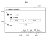
- the user can switch modes using the enable button 602 and disable button 603 on the analysis tank priority use setting screen 601 shown in FIG. 6. Specifically, the user selects whether to enable or disable the function of this embodiment, and sets it using the apply button 606 and cancel button 607. When this function is enabled using the enable button 602, the user can further set whether or not to specify a time using the time designation setting button 604. When specifying the time for enabling this function using the time designation setting button 604, the enabled time can be set in the designated time input field 605. When closing the analysis tank priority use setting screen 601, the close button 608 is pressed.
- the present invention is not limited to the above-described embodiment and modifications, but includes various other modifications.
- the above-described embodiment has been described in detail to clearly explain the present invention, and is not necessarily limited to having all of the configurations described.
- the automatic analyzer may have a function of masking other analysis tanks and a function of allowing the user to confirm this.
- 101...control computer 102...sample input section, 103...sample recovery section, 104...ID reader, 105...transport line, 106...analysis tank, 107...dispensing mechanism, 108...sample container, 109...carrier, 110...analysis module, 111...transport line within analysis unit, 501...analysis tank selection screen, 502...ion selective electrode information display field, 503, 606...apply button, 504, 607...cancel button, 505, 608...close button, 506...analysis tank selection button, 601...analysis tank priority use setting screen, 602...enable button, 603...disable button, 604...time designation setting button, 605...designated time input field.
Landscapes
- Health & Medical Sciences (AREA)
- General Health & Medical Sciences (AREA)
- Engineering & Computer Science (AREA)
- Biomedical Technology (AREA)
- Physics & Mathematics (AREA)
- Primary Health Care (AREA)
- Public Health (AREA)
- Business, Economics & Management (AREA)
- Epidemiology (AREA)
- General Business, Economics & Management (AREA)
- Medical Informatics (AREA)
- Life Sciences & Earth Sciences (AREA)
- Chemical & Material Sciences (AREA)
- Analytical Chemistry (AREA)
- Biochemistry (AREA)
- General Physics & Mathematics (AREA)
- Immunology (AREA)
- Pathology (AREA)
- Automatic Analysis And Handling Materials Therefor (AREA)
Priority Applications (3)
| Application Number | Priority Date | Filing Date | Title |
|---|---|---|---|
| JP2025524004A JPWO2024247823A1 (https=) | 2023-05-30 | 2024-05-21 | |
| CN202480010030.2A CN120548477A (zh) | 2023-05-30 | 2024-05-21 | 自动分析装置以及分析槽的分配方法 |
| EP24815307.4A EP4722727A1 (en) | 2023-05-30 | 2024-05-21 | Automatic analysis device and method for allocating analysis tank |
Applications Claiming Priority (2)
| Application Number | Priority Date | Filing Date | Title |
|---|---|---|---|
| JP2023088603 | 2023-05-30 | ||
| JP2023-088603 | 2023-05-30 |
Publications (1)
| Publication Number | Publication Date |
|---|---|
| WO2024247823A1 true WO2024247823A1 (ja) | 2024-12-05 |
Family
ID=93657548
Family Applications (1)
| Application Number | Title | Priority Date | Filing Date |
|---|---|---|---|
| PCT/JP2024/018709 Ceased WO2024247823A1 (ja) | 2023-05-30 | 2024-05-21 | 自動分析装置及び分析槽の割当方法 |
Country Status (4)
| Country | Link |
|---|---|
| EP (1) | EP4722727A1 (https=) |
| JP (1) | JPWO2024247823A1 (https=) |
| CN (1) | CN120548477A (https=) |
| WO (1) | WO2024247823A1 (https=) |
Citations (5)
| Publication number | Priority date | Publication date | Assignee | Title |
|---|---|---|---|---|
| US5526705A (en) * | 1994-08-05 | 1996-06-18 | Tyler Limited Partnership | Automated work station for analyzing soil samples |
| JP2004219352A (ja) * | 2003-01-17 | 2004-08-05 | Toshiba Corp | 分析装置及び管理システム |
| JP2004317521A (ja) * | 2004-05-28 | 2004-11-11 | Dkk Toa Corp | メモリー付き電極を備えた計測装置 |
| JP2020041968A (ja) * | 2018-09-13 | 2020-03-19 | 株式会社日立ハイテクノロジーズ | 電解質濃度測定装置 |
| WO2022014096A1 (ja) | 2020-07-16 | 2022-01-20 | 株式会社日立ハイテク | 電解質分析装置 |
-
2024
- 2024-05-21 CN CN202480010030.2A patent/CN120548477A/zh active Pending
- 2024-05-21 WO PCT/JP2024/018709 patent/WO2024247823A1/ja not_active Ceased
- 2024-05-21 JP JP2025524004A patent/JPWO2024247823A1/ja active Pending
- 2024-05-21 EP EP24815307.4A patent/EP4722727A1/en active Pending
Patent Citations (5)
| Publication number | Priority date | Publication date | Assignee | Title |
|---|---|---|---|---|
| US5526705A (en) * | 1994-08-05 | 1996-06-18 | Tyler Limited Partnership | Automated work station for analyzing soil samples |
| JP2004219352A (ja) * | 2003-01-17 | 2004-08-05 | Toshiba Corp | 分析装置及び管理システム |
| JP2004317521A (ja) * | 2004-05-28 | 2004-11-11 | Dkk Toa Corp | メモリー付き電極を備えた計測装置 |
| JP2020041968A (ja) * | 2018-09-13 | 2020-03-19 | 株式会社日立ハイテクノロジーズ | 電解質濃度測定装置 |
| WO2022014096A1 (ja) | 2020-07-16 | 2022-01-20 | 株式会社日立ハイテク | 電解質分析装置 |
Non-Patent Citations (1)
| Title |
|---|
| See also references of EP4722727A1 |
Also Published As
| Publication number | Publication date |
|---|---|
| EP4722727A1 (en) | 2026-04-08 |
| CN120548477A (zh) | 2025-08-26 |
| JPWO2024247823A1 (https=) | 2024-12-05 |
Similar Documents
| Publication | Publication Date | Title |
|---|---|---|
| JP7602524B2 (ja) | 自動分析装置及び自動分析方法 | |
| US8409507B2 (en) | Automatic analyzer | |
| JP4558017B2 (ja) | 自動分析装置および自動分析装置の使用方法 | |
| US10802000B2 (en) | Method of calibrating a chromatography system | |
| EP2843418B1 (en) | Sample analyzer and sample analyzing method | |
| JP6879871B2 (ja) | 自動分析装置 | |
| JP6466294B2 (ja) | 自動分析装置 | |
| JP2013148564A (ja) | 自動分析装置 | |
| JP5378962B2 (ja) | 動的搬送計画装置及び動的搬送計画方法 | |
| JP6918840B2 (ja) | 自動分析装置 | |
| WO2024247823A1 (ja) | 自動分析装置及び分析槽の割当方法 | |
| CN113092794A (zh) | 工作负荷仪器掩蔽 | |
| JP7144667B2 (ja) | 自動分析装置および自動分析システム、ならびに試料の自動分析方法 | |
| US20050220671A1 (en) | Controller for automated immunoassay system | |
| CN114200071B (zh) | 一种色谱仪集群控制方法及装置 | |
| JP7391224B2 (ja) | 電解質分析装置 | |
| JP7176612B2 (ja) | 液体クロマトグラフ | |
| JPWO2022014096A5 (https=) | ||
| JP4383976B2 (ja) | 自動分析装置 | |
| JP7359514B1 (ja) | 液体クロマトグラフィー装置、溶液管理方法、プログラム | |
| CN118575225A (zh) | 用于操作实验室系统的方法以及实验室系统 | |
| CN116783489A (zh) | 自动分析装置 | |
| CN112666361A (zh) | 耗材信息的处理的方法以及相关设备 | |
| JP7671324B2 (ja) | ヘルスケアデータ処理能力管理 | |
| EP4621795A1 (en) | Computer-implemented method for processing a request for an analytical test |
Legal Events
| Date | Code | Title | Description |
|---|---|---|---|
| 121 | Ep: the epo has been informed by wipo that ep was designated in this application |
Ref document number: 24815307 Country of ref document: EP Kind code of ref document: A1 |
|
| ENP | Entry into the national phase |
Ref document number: 2025524004 Country of ref document: JP Kind code of ref document: A |
|
| WWE | Wipo information: entry into national phase |
Ref document number: 2025524004 Country of ref document: JP |
|
| WWE | Wipo information: entry into national phase |
Ref document number: 202480010030.2 Country of ref document: CN |
|
| WWP | Wipo information: published in national office |
Ref document number: 202480010030.2 Country of ref document: CN |
|
| NENP | Non-entry into the national phase |
Ref country code: DE |
|
| WWE | Wipo information: entry into national phase |
Ref document number: 2024815307 Country of ref document: EP |
|
| ENP | Entry into the national phase |
Ref document number: 2024815307 Country of ref document: EP Effective date: 20260102 |
|
| ENP | Entry into the national phase |
Ref document number: 2024815307 Country of ref document: EP Effective date: 20260102 |
|
| ENP | Entry into the national phase |
Ref document number: 2024815307 Country of ref document: EP Effective date: 20260102 |
|
| ENP | Entry into the national phase |
Ref document number: 2024815307 Country of ref document: EP Effective date: 20260102 |
|
| ENP | Entry into the national phase |
Ref document number: 2024815307 Country of ref document: EP Effective date: 20260102 |
|
| ENP | Entry into the national phase |
Ref document number: 2024815307 Country of ref document: EP Effective date: 20260102 |