WO2024247745A1 - バルーンカテーテル用バルーン及びそれを備えるバルーンカテーテル - Google Patents
バルーンカテーテル用バルーン及びそれを備えるバルーンカテーテル Download PDFInfo
- Publication number
- WO2024247745A1 WO2024247745A1 PCT/JP2024/018121 JP2024018121W WO2024247745A1 WO 2024247745 A1 WO2024247745 A1 WO 2024247745A1 JP 2024018121 W JP2024018121 W JP 2024018121W WO 2024247745 A1 WO2024247745 A1 WO 2024247745A1
- Authority
- WO
- WIPO (PCT)
- Prior art keywords
- balloon
- protrusion
- section
- notch
- height
- Prior art date
- Legal status (The legal status is an assumption and is not a legal conclusion. Google has not performed a legal analysis and makes no representation as to the accuracy of the status listed.)
- Ceased
Links
Images





Classifications
-
- A—HUMAN NECESSITIES
- A61—MEDICAL OR VETERINARY SCIENCE; HYGIENE
- A61B—DIAGNOSIS; SURGERY; IDENTIFICATION
- A61B17/00—Surgical instruments, devices or methods
- A61B17/32—Surgical cutting instruments
- A61B17/3205—Excision instruments
- A61B17/3207—Atherectomy devices working by cutting or abrading; Similar devices specially adapted for non-vascular obstructions
- A61B17/320725—Atherectomy devices working by cutting or abrading; Similar devices specially adapted for non-vascular obstructions with radially expandable cutting or abrading elements
-
- A—HUMAN NECESSITIES
- A61—MEDICAL OR VETERINARY SCIENCE; HYGIENE
- A61M—DEVICES FOR INTRODUCING MEDIA INTO, OR ONTO, THE BODY; DEVICES FOR TRANSDUCING BODY MEDIA OR FOR TAKING MEDIA FROM THE BODY; DEVICES FOR PRODUCING OR ENDING SLEEP OR STUPOR
- A61M25/00—Catheters; Hollow probes
- A61M25/10—Balloon catheters
-
- A—HUMAN NECESSITIES
- A61—MEDICAL OR VETERINARY SCIENCE; HYGIENE
- A61M—DEVICES FOR INTRODUCING MEDIA INTO, OR ONTO, THE BODY; DEVICES FOR TRANSDUCING BODY MEDIA OR FOR TAKING MEDIA FROM THE BODY; DEVICES FOR PRODUCING OR ENDING SLEEP OR STUPOR
- A61M25/00—Catheters; Hollow probes
- A61M25/10—Balloon catheters
- A61M25/1002—Balloon catheters characterised by balloon shape
-
- A—HUMAN NECESSITIES
- A61—MEDICAL OR VETERINARY SCIENCE; HYGIENE
- A61B—DIAGNOSIS; SURGERY; IDENTIFICATION
- A61B17/00—Surgical instruments, devices or methods
- A61B17/22—Implements for squeezing-off ulcers or the like on inner organs of the body; Implements for scraping-out cavities of body organs, e.g. bones; for invasive removal or destruction of calculus using mechanical vibrations; for removing obstructions in blood vessels, not otherwise provided for
- A61B2017/22051—Implements for squeezing-off ulcers or the like on inner organs of the body; Implements for scraping-out cavities of body organs, e.g. bones; for invasive removal or destruction of calculus using mechanical vibrations; for removing obstructions in blood vessels, not otherwise provided for with an inflatable part, e.g. balloon, for positioning, blocking, or immobilisation
- A61B2017/22061—Implements for squeezing-off ulcers or the like on inner organs of the body; Implements for scraping-out cavities of body organs, e.g. bones; for invasive removal or destruction of calculus using mechanical vibrations; for removing obstructions in blood vessels, not otherwise provided for with an inflatable part, e.g. balloon, for positioning, blocking, or immobilisation for spreading elements apart
-
- A—HUMAN NECESSITIES
- A61—MEDICAL OR VETERINARY SCIENCE; HYGIENE
- A61M—DEVICES FOR INTRODUCING MEDIA INTO, OR ONTO, THE BODY; DEVICES FOR TRANSDUCING BODY MEDIA OR FOR TAKING MEDIA FROM THE BODY; DEVICES FOR PRODUCING OR ENDING SLEEP OR STUPOR
- A61M25/00—Catheters; Hollow probes
- A61M25/10—Balloon catheters
- A61M25/1002—Balloon catheters characterised by balloon shape
- A61M2025/1004—Balloons with folds, e.g. folded or multifolded
-
- A—HUMAN NECESSITIES
- A61—MEDICAL OR VETERINARY SCIENCE; HYGIENE
- A61M—DEVICES FOR INTRODUCING MEDIA INTO, OR ONTO, THE BODY; DEVICES FOR TRANSDUCING BODY MEDIA OR FOR TAKING MEDIA FROM THE BODY; DEVICES FOR PRODUCING OR ENDING SLEEP OR STUPOR
- A61M25/00—Catheters; Hollow probes
- A61M25/10—Balloon catheters
- A61M2025/1043—Balloon catheters with special features or adapted for special applications
- A61M2025/1086—Balloon catheters with special features or adapted for special applications having a special balloon surface topography, e.g. pores, protuberances, spikes or grooves
-
- A—HUMAN NECESSITIES
- A61—MEDICAL OR VETERINARY SCIENCE; HYGIENE
- A61M—DEVICES FOR INTRODUCING MEDIA INTO, OR ONTO, THE BODY; DEVICES FOR TRANSDUCING BODY MEDIA OR FOR TAKING MEDIA FROM THE BODY; DEVICES FOR PRODUCING OR ENDING SLEEP OR STUPOR
- A61M25/00—Catheters; Hollow probes
- A61M25/10—Balloon catheters
- A61M2025/1043—Balloon catheters with special features or adapted for special applications
- A61M2025/109—Balloon catheters with special features or adapted for special applications having balloons for removing solid matters, e.g. by grasping or scraping plaque, thrombus or other matters that obstruct the flow
-
- A—HUMAN NECESSITIES
- A61—MEDICAL OR VETERINARY SCIENCE; HYGIENE
- A61M—DEVICES FOR INTRODUCING MEDIA INTO, OR ONTO, THE BODY; DEVICES FOR TRANSDUCING BODY MEDIA OR FOR TAKING MEDIA FROM THE BODY; DEVICES FOR PRODUCING OR ENDING SLEEP OR STUPOR
- A61M25/00—Catheters; Hollow probes
- A61M25/10—Balloon catheters
- A61M25/104—Balloon catheters used for angioplasty
Definitions
- the present invention relates to a balloon for a balloon catheter and a balloon catheter equipped with the same.
- Angioplasty in which a balloon catheter is inserted into the narrowed area of a blood vessel and the balloon is expanded to expand the blood vessel and ensure blood flow, is widely used as a minimally invasive therapy.
- Angioplasty is used to treat diseases such as myocardial infarction caused by narrowing of the coronary arteries of the heart, and to treat narrowing that occurs in shunts for dialysis.
- ISR In-Stent-Restenosis
- the neointima is soft and has a slippery surface, so when a typical balloon catheter is used to expand the balloon, the position of the balloon can shift from the lesion, causing damage to the blood vessel.
- Patent Document 1 discloses a balloon catheter that has a scoring element made of a polymeric material with higher rigidity than the polymeric material that forms the balloon body, and the scoring element is flattened at one end and the other end of the balloon.
- Patent Document 2 discloses a scoring balloon structure in which the height of the scoring element decreases along the tapered shape of the balloon
- Patent Document 3 discloses a balloon catheter in which an outer protrusion is provided on the straight tube part of the balloon and an inner protrusion is provided on the tapered part.
- Patent Document 4 the height of the scoring element decreases at both ends of the balloon, or an inner protrusion is provided instead of an outer protrusion.
- a balloon catheter that has a high protrusion in which the protrusion located on the distal tapered part protrudes more than the protrusion located on the straight tube part of the balloon (Patent Document 4).
- Balloon catheters are inserted into body cavities in a deflated and folded state and delivered to the treatment site.
- the balloon catheters disclosed in Patent Documents 1 to 3 attempt to improve the passability of the balloon by suppressing the height of the scoring element at the tip of the balloon to prevent the outer diameter from becoming large so that it can be easily inserted into body cavities.
- the height of the protrusion located in the tip cone region is high so that when only the tip cone region is introduced into the lesion and the balloon is expanded, the element provided in the tip cone region can be used to incise the lesion while expanding the balloon.
- the balloon would be advanced or retreated to incise the stenosis while in the deflated state.
- the present invention aims to provide a balloon for a balloon catheter, which has a protrusion on its surface, and which can incise a stricture when in a contracted state, improves the expansion function of the stricture when in an expanded state, and can be easily folded when the balloon is contracted, thereby reducing the outer diameter of the balloon and improving insertion performance, and a balloon catheter equipped with the balloon.
- a balloon for a balloon catheter having a straight tube section, a proximal taper section located proximal to the straight tube section, a proximal sleeve section located proximal to the proximal taper section, a distal taper section located distal to the straight tube section, and a distal sleeve section located distal to the distal taper section, the balloon having an outer surface and an inner surface, and a protrusion protruding radially outward from the outer surface of the balloon body section and extending in the longitudinal axis direction.
- the protrusion in the straight tube portion has an ST portion notch
- the protrusion in the distal tapered portion has a DT portion notch
- a depth D3 of the ST portion notch and a depth D4 of the DT portion notch are both 50 ⁇ m or more
- the depth D3 of the ST portion notch, the height H3 of the protrusion in the straight tube portion, the depth D4 of the DT portion notch, and the height H4 of the protrusion in the distal tapered portion satisfy the relationship D3/H3 ⁇ D4/H4.
- the protrusion is arranged on the distal tapered section, where the outer diameter of the balloon body when expanded gradually decreases from the straight tube section, the protrusion on the distal tapered section is easily exposed from the vanes when the balloon is deflated, and can contribute to the incision of the stenosis.
- the stenosis can be incised by moving the balloon forward (crawling forward) while it is deflated, but since the ratio D4/H4 of the depth D4 of the DT notch of the protrusion on the distal tapered section to the height H4 of the protrusion on the distal tapered section is relatively large, each segment of the protrusion divided by the DT notch on the distal tapered section can act on the stenosis, and the edge formed by the boundary between the protrusion and the DT notch can improve the effect of cutting into the stenosis and the effect of scraping out the stenosis, so the stenosis can be expanded by the protrusion on the distal tapered section by performing an operation such as crawling forward when the balloon is deflated.
- the value of the ratio D3/H3 between the depth D3 of the ST section notch of the protrusion in the straight tube section and the height H3 of the protrusion in the straight tube section is relatively small, the rigidity of the protrusion in the straight tube section is improved, and when the protrusion in the straight tube section is exposed from the wing during the expansion of the balloon, the expansion function of the stenosis section by the protrusion in the straight tube section can be improved. Furthermore, since the value of the ratio D3/H3 is relatively small, when the balloon contracts and the wing is folded, the wing is prevented from getting caught in the notch in the straight tube section. As a result, the wing can be easily folded to reduce the outer diameter of the balloon, and the insertion ability of the balloon can be improved when the balloon is contracted and removed from the body or when it is reinserted into another treatment site.
- the balloon for a balloon catheter according to the embodiment of the present invention is preferably any one of the following [2] to [16].
- the present invention also provides the following: [17] A balloon catheter comprising the balloon for a balloon catheter according to any one of [1] to [16] above.
- the balloon for balloon catheter and the balloon catheter including the balloon catheter have the same. Since the value of the ratio D4/H4 of the depth and height of the notch of the protrusion in the distal tapered portion is relatively large, the effect of cutting into the narrowed portion by the edge formed by the boundary between the protrusion and the notch and the effect of scraping out the narrowed portion can be improved. Therefore, by performing an operation such as crawling forward when the balloon is deflated, the narrowed portion can be expanded by the protrusion in the distal tapered portion in the deflated state.
- the value of the ratio D3/H3 of the depth and height of the notch of the protrusion in the straight tube portion is relatively small, the rigidity of the protrusion in the straight tube portion can be improved, and the function of expanding the narrowed portion in the expanded state of the balloon can be improved. Furthermore, since the value of the ratio D3/H3 is relatively small, the wings can be easily folded when the balloon is deflated, making it easy to remove the balloon from the body and reinsert it into another treatment site.
- FIG. 1 is a side view of a balloon catheter according to an embodiment of the present invention.
- 2 is a cross-sectional view of the balloon catheter shown in FIG. 1 taken along line II-II.
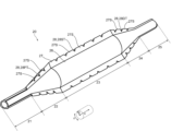
- FIG. 2 is a perspective view of a balloon of the balloon catheter shown in FIG. 1 .
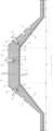
- 1 is a longitudinal cross-sectional view of a balloon according to one embodiment of the present invention.
- FIG. FIG. 2 is a side view of a balloon in a deflated state according to one embodiment of the present invention.
- 6 is a cross-sectional view of the balloon shown in FIG. 5 taken along line VI-VI.
- 7 is a cross-sectional view of the balloon shown in FIG. 5 along line VII-VII.
- FIG. 13 is a perspective view of a balloon according to another embodiment of the present invention.
- FIG. 9 is a side view of the balloon shown in FIG. 8 in a deflated state.
- 10 is a cross-sectional view of the balloon shown in FIG. 9 taken along the line XX.
- FIG. 13 is a perspective view of a balloon according to yet another embodiment of the present invention.
- 11 is a longitudinal cross-sectional view of a balloon according to yet another embodiment of the present invention.
- FIG. FIG. 12 is a side view of the balloon shown in FIG. 11 in a deflated state.
- FIG. 14 is a cross-sectional view of the balloon shown in FIG. 13 taken along line XIV-XIV.
- 11 is a longitudinal cross-sectional view of a balloon according to yet another embodiment of the present invention.
- FIG. 11 is a longitudinal cross-sectional view of a balloon according to yet another embodiment of the present invention.
- FIG. 11 is a longitudinal cross-sectional view of a balloon according to yet another embodiment of the present invention.
- FIG. 11 is a longitudinal cross
- Fig. 1 is a side view of a balloon catheter according to an embodiment of the present invention.
- Fig. 2 is a II-II cross-sectional view of the balloon catheter shown in Fig. 1, showing a cross-section perpendicular to the longitudinal axis direction of a portion of the straight tube portion of the balloon where no notch is arranged in the protruding portion.
- Fig. 3 is a perspective view of the balloon of the balloon catheter shown in Fig. 1.
- Figs. 2 and 3 show the balloon in an expanded state.
- FIG. 4 is a cross-sectional view of the longitudinal axis direction of a balloon according to an embodiment of the present invention, showing an enlarged view of a portion where a protruding portion is arranged.
- Fig. 5 is a side view of a balloon according to an embodiment of the present invention in a contracted state.
- Fig. 6 is a VI-VI cross-sectional view of the balloon shown in Fig. 5, showing a configuration in which wings are formed on the straight tube portion in a contracted state and the protruding portion of the straight tube portion is covered by the wings.
- Fig. 7 is a VII-VII cross-sectional view of the balloon shown in Fig.
- FIG. 8 is a perspective view of a balloon according to another embodiment of the present invention.
- FIG. 8 shows a balloon in an expanded state.
- FIG. 9 is a side view of the balloon shown in FIG. 8 in a contracted state.
- FIG. 10 is an X-X cross-sectional view of the balloon shown in FIG. 9, showing a cross-section perpendicular to the longitudinal axis direction of the proximal taper portion in a contracted state.
- FIG. 11 is a perspective view of a balloon according to yet another embodiment of the present invention.
- FIG. 11 shows a balloon in an expanded state.
- FIG. 12 is a cross-sectional view of a balloon according to yet another embodiment of the present invention in a longitudinal direction, showing an enlarged view of a portion where a protrusion is arranged.
- FIG. 13 is a side view of the balloon shown in FIG. 11 in a contracted state.
- FIG. 14 is a cross-sectional view of the balloon shown in FIG. 13 along XIV-XIV, showing a cross-section perpendicular to the longitudinal axis direction of the proximal taper portion in a contracted state.
- FIGS. 15 and 16 are cross-sectional views of a balloon according to yet another embodiment of the present invention in a longitudinal direction, showing an enlarged view of a portion where a protrusion is arranged.
- the balloon 20 is provided at the distal portion of the balloon catheter 10.
- the balloon 20 is connected to the distal end of the shaft 30, and the balloon 20 can be expanded by introducing fluid through the inner cavity of the shaft 30, and can be deflated by discharging the fluid.
- fluid can be introduced or discharged using an indeflator (balloon pressurizer).
- the fluid may be a pressurized fluid pressurized by a pump or the like.
- the balloon catheter 10 will be described in detail in the section "2. Balloon Catheter.”
- the balloon 20 has a longitudinal axis direction x, a radial direction y that is a direction connecting the centroid of the circumscribing circle of the balloon 20 and a point on the circumscribing circle in a cross section perpendicular to the longitudinal axis direction x, and a circumscribing direction z that is a direction along the circumscribing circle.
- the direction toward the user's hand in the longitudinal axis direction x is referred to as the proximal side
- the side opposite the proximal side i.e., the direction toward the subject of treatment
- the members and parts other than the balloon 20 each have a longitudinal axis direction, a radial direction, and a circumferential direction, which may or may not be the same as the longitudinal axis direction x, radial direction y, and circumferential direction z of the balloon 20.
- this specification describes all members and parts as having the same longitudinal axis direction, radial direction, and circumferential direction as the longitudinal axis direction x, radial direction y, and circumferential direction z of the balloon 20.
- a balloon 20 for a balloon catheter has a straight tube section 23, a proximal taper section 22 located proximal to the straight tube section 23, a proximal sleeve section 21 located proximal to the proximal taper section 22, a distal taper section 24 located distal to the straight tube section 23, and a distal sleeve section 25 located distal to the distal taper section 24.
- the proximal taper section 22 and the distal taper section 24 are preferably formed so that the balloon body 26 reduces in diameter as it moves away from the straight tube section 23.
- the straight tube section 23 of the balloon 20 can have the maximum diameter in the expanded state, and by expanding the balloon 20 at the lesion, the straight tube section 23 can be brought into sufficient contact with the lesion, making it easy to expand or incise the stenosis.
- the outer diameter of the proximal and distal ends of the balloon 20 can be reduced when the balloon 20 is deflated, thereby reducing the step between the shaft 30 and the balloon 20, making it easier to insert the balloon 20 into a body cavity, a forceps channel of an endoscope, or a delivery catheter such as a guiding catheter.
- the balloon body 26 when the balloon 20 is deflated, the balloon body 26 is formed into wings 29, but since the diameter of the balloon body 26 in the proximal taper section 22 and the distal taper section 24 becomes smaller as it moves away from the straight tube section 23, the length of the wings 29 in the circumferential direction z becomes shorter. Therefore, when the balloon 20 is deflated and the wings 29 are wrapped around the shaft 30, at least a portion of the protrusions 27 in the proximal taper section 22 and the distal taper section 24 can be exposed from the wings 29, and the exposed portions of the protrusions 27 can incise the narrowed area even when the balloon 20 is deflated.
- the proximal sleeve portion 21 and the distal sleeve portion 25 are portions that do not expand even when the balloon 20 is in an expanded state. This allows at least a portion of the proximal sleeve portion 21 and the distal sleeve portion 25 to be stably fixed to the shaft 30.
- the shaft 30 has an inner shaft 31 and an outer shaft 32, at least a portion of the proximal sleeve portion 21 can be fixed to the outer shaft 32, and at least a portion of the distal sleeve portion 25 can be fixed to the inner shaft 31.
- the balloon 20 has a balloon body 26 having an outer surface and an inner surface, and a protrusion 27 that protrudes outward in the radial direction y from the outer surface of the balloon body 26 and extends in the longitudinal axis direction x.
- the balloon body 26 is the part that defines the basic shape of the balloon 20, and its outer shape is preferably a cylindrical shape in the straight tube section 23, a truncated cone shape in the tapered section, and a cylindrical shape with a smaller diameter than the straight tube section 23 in the sleeve section.
- the protrusion 27 is a part that is formed thicker than the thickness of the part where the protrusion 27 is not provided, i.e., the part where the balloon body 26 is exposed.
- the thickness of the protruding portion 27 of the balloon 20 is, for example, preferably 1.2 times or more, more preferably 1.5 times or more, even more preferably 1.8 times or more, 2.0 times or more, or 2.5 times or more, the thickness of the portion of the balloon 20 where the protruding portion 27 is not provided.
- the thickness of the portion of the balloon 20 where the protrusion 27 is not provided i.e., the thickness of the balloon main body 26, is uniform in the longitudinal axis direction x and the circumferential direction z.
- the unevenness does not include surface roughness that is inevitably formed during manufacturing. This makes it easier to uniformly expand the balloon 20, and makes it easier to achieve the scoring function of the protrusion 27 as desired.
- the thickness of the balloon main body 26 in the straight tube section 23, the thickness of the balloon main body 26 in the tapered section, and the thickness of the balloon main body 26 in the sleeve section may be different from each other, and the thickness of the balloon main body 26 in the straight tube section 23 may be the thinnest. This makes it possible to obtain a balloon 20 with improved flexibility.
- the protrusion 27 has an apex 27t and a base 27b.
- the apex 27t is a portion including the outer end of the protrusion 27 in the radial direction y
- the base 27b is a portion including the boundary with the balloon main body 26, i.e., the inner end of the protrusion 27 in the radial direction y.
- the apex 27t does not necessarily have to have a corner as shown in FIG. 2, and may be of any shape. Even if the apex 27t has any shape, the outer end of the protrusion 27 in the radial direction y can be uniquely defined, and the portion including the outer end can be referred to as the apex 27t.
- the balloon 20 has a protrusion 27, which gives the balloon 20 a scoring function.
- a protrusion 27 gives the balloon 20 a scoring function.
- the protrusion 27 is provided on the outer surface of the balloon body 26 so as to extend in a ridge-like manner in the longitudinal direction x.
- the protrusion 27 has a notch 28, which will be described later, and the protrusion 27 extending in a ridge-like manner in the longitudinal direction x may be interrupted by the notch 28. Even in this case, if the protrusion 27 extends to both the distal and proximal sides of the notch 28 in the longitudinal direction x, it can be said that one protrusion 27 extends in the longitudinal direction x.
- multiple protrusions 27 may be provided in the circumferential direction z, or, although not shown, only one protrusion 27 may be provided in the circumferential direction z.
- the number of protrusions 27 in the circumferential direction z may be 1 or more, 2 or more, 3 or more, 4 or more, 6 or more, and may be 20 or less, 15 or less, or 10 or less.
- the multiple protrusions 27 are preferably spaced apart in the circumferential direction z, and more preferably are arranged at approximately equal intervals in the circumferential direction z. The separation distance is preferably longer than the maximum length of the protrusions 27 in the circumferential direction z.
- the protrusion 27 is preferably provided on the straight tube section 23 and the distal tapered section 24, and the range in which the protrusion 27 is arranged in the longitudinal axis direction x may be a partial section or the entire section of the straight tube section 23, and may be a partial section or the entire section of the distal tapered section 24.
- the protrusion 27 may be arranged on the proximal tapered section 22, and the range in which the protrusion 27 is arranged in the longitudinal axis direction x may be a partial section or the entire section of the proximal tapered section 22.
- the protrusion 27 may be provided on the proximal sleeve section 21 and/or the distal sleeve section 25, and the range in which the protrusion 27 is arranged in the longitudinal axis direction x may be a partial section or the entire section of the proximal sleeve section 21 and/or the distal sleeve section 25.
- the range in which the protrusion 27 is arranged in the longitudinal axis direction x includes the portion that is torn by the notch 28 described later.
- the length of the exposed portion in the longitudinal direction x is preferably shorter than the maximum length in the longitudinal direction x of the protruding portion segment 27S described below.
- one protruding portion 27 extends in the longitudinal direction x including the notch 28.
- the protruding portion 27 may be provided in a portion of each of the proximal taper portion 22 and the straight tube portion 23 in the longitudinal direction x, and multiple protruding portions 27 may be arranged in the longitudinal direction x by making the length of the exposed portion in the longitudinal direction x longer than the maximum length in the longitudinal direction x of the protruding portion segment 27S.
- the cross-sectional shape of the protrusion 27 in a cross section perpendicular to the longitudinal axis direction x may be any shape, such as a triangle, a rectangle, a polygon, a semicircle, a part of a circle, an approximately circle, a sector, a wedge, a convex shape, a spindle shape, or a combination thereof.
- triangles, rectangles, and polygons include shapes with clear corner apexes and straight sides, as well as so-called rounded polygons with rounded corners and shapes with at least some curved sides.
- the cross-sectional shape of the protrusion 27 may be an irregular shape having irregularities, chips, or the like.
- the protrusion 27 may have a cross-sectional shape that differs depending on the position in the longitudinal axis direction x, such as a protrusion 27 having an approximately triangular cross-sectional shape in a portion where the notch 28 is not provided and a cross-sectional shape that is approximately trapezoidal in a portion where the notch 28 is provided.
- the protrusion 27 in the straight pipe section 23 has an ST section notch 28ST
- the protrusion 27 in the distal tapered section 24 has a DT section notch 28DT.
- the ST section notch 28ST is a notch provided in the straight pipe section 23
- the DT section notch 28DT is a notch provided in the distal tapered section 24, but hereafter, the notches may be collectively referred to as notches 28 regardless of where they are provided.
- the notch 28 can be provided so as to form a recess in the top 27t of the protrusion 27 extending in the longitudinal axis direction x.
- the notch 28 may be formed by cutting away a portion of the top 27t of the protrusion 27.
- the notch 28 has a bottom 28b that is located at the deepest position in the depth direction of the notch 28 described below, and a top 28t that is the boundary with the top 27t of the protrusion 27.
- the notch 28 is provided so as to form a recess in the top 27t of the protrusion 27, it is preferable that one notch 28 has two tops 28t in a cross section in the longitudinal axis direction x that passes through the top 27t of the protrusion 27.
- the protrusion segments 27S can be arranged at both ends of the ST portion notch 28ST in the longitudinal axis direction x, and by providing the DT portion notch 28DT in the distal tapered portion 24, the protrusion segments 27S can be arranged at both ends of the DT portion notch 28DT in the longitudinal axis direction x.
- the apex 28t of the notch 28 is located at the end of the protrusion segment 27S.
- the depth D3 of the ST section notch 28ST, the height H3 of the protrusion 27 in the straight pipe section 23, the depth D4 of the DT section notch 28DT, and the height H4 of the protrusion 27 in the distal taper section 24 satisfy the relationship D3/H3 ⁇ D4/H4.
- the balloon 20 can be in a contracted state before a fluid is introduced into the lumen or after the fluid once introduced is discharged.
- the balloon body 26 in the straight tube portion 23 has a cylindrical shape as shown in FIG. 2.
- wings 29 are formed in the balloon 20 as shown in FIG. 5 to FIG. 7.
- the wings 29 are folded to reduce the outer diameter of the balloon 20 so that the lumen wall of the balloon body portion 26 approaches the shaft 30. That is, as shown in FIG. 2, the balloon 20 in the expanded state can be said to have a wing forming portion 29a, and the longer the length of the wing forming portion 29a in the circumferential direction z, the longer the wing 29 can be formed.
- the straight tube portion 23 is the portion that has the maximum diameter when expanded, so the length of the wing 29 in the straight tube portion 23 is long, and the protruding portion 27 in the straight tube portion 23 can be covered by the wing 29 in the contracted state.
- the length of the wings 29 is short, so that at least a portion of the protrusion 27 in the distal taper section 24, particularly the apex 27t of the protrusion 27, can be exposed from the wings 29 even in the contracted state.
- the protrusion 27 in the distal taper section 24 can contribute to the incision of the stenosis with the wings 29 folded when the balloon 20 is contracted.
- each of the protrusion segments 27S separated by the DT portion notch 28DT in the distal taper portion 24 can easily act on the narrowed portion, and the effect of cutting into the narrowed portion by the edge formed at the boundary between the protrusion segment 27S and the DT portion notch 28DT, i.e., the apex 28t of the notch 28, and the effect of scraping out the narrowed portion can be improved. Therefore, by performing an operation such as moving the balloon 20 forward (crawling forward) while it is deflated, the pro
- the rigidity of the protrusion 27 of the straight tube section 23 is improved, and the stenosis section expansion function of the protrusion 27 of the straight tube section 23 can be improved when the protrusion 27 of the straight tube section 23 is exposed from the wing 29 when the balloon 20 is expanded.
- the depth of the notch 28 can be the distance between the point where a perpendicular line intersects with an imaginary line connecting the two apexes 28t of the notch 28 and the point where the perpendicular line intersects with the bottom 28b of the notch 28 when a perpendicular line is drawn from the imaginary line connecting the two apexes 28t of the notch 28 to the bottom 28b of the notch 28 in a cross section in the longitudinal axis direction x passing through the apex 27t of the protrusion 27.
- FIG. 4 the depth of the notch 28 can be the distance between the point where a perpendicular line intersects with an imaginary line connecting the two apexes 28t of the notch 28 and the point where the perpendicular line intersects with the bottom 28b of the notch 28 when a perpendicular line is drawn from the imaginary line connecting the two apexes 28t of the notch 28 to the bottom 28b of the notch 28 in a cross section in the longitudinal axis
- the imaginary line connecting the apexes 28t of the ST portion notch 28ST is parallel to the longitudinal axis direction x, and the depth D3 is obtained as the distance between the imaginary line in the radial direction y and the bottom 28b of the ST portion notch 28ST.
- the imaginary line connecting the apexes 28t of the DT portion notch 28DT is not parallel to the longitudinal axis direction x, but the depth D4 can be obtained by drawing a perpendicular line from the imaginary line to the bottom 28b of the DT portion notch 28DT.
- the shape of the notch 28 is not particularly limited. In a cross section in the longitudinal direction x passing through the top 27t of the protrusion 27, the shape of the notch 28 may be V-shaped, U-shaped, a rectangular shape with one side removed, or a combination of these shapes. Regardless of the shape, the bottom 28b arranged at the deepest position in the depth direction can be specified, so the depth can be determined by the above definition. The bottom 28b of the notch 28 may or may not reach the base 27b of the protrusion 27. The balloon main body 26 may be exposed at the bottom of the notch 28 by the bottom 28b of the notch 28 reaching the base 27b of the protrusion 27.
- the exposed part is considered to be a part of the notch 28 and not a non-existent part of the protrusion 27.
- the height H3 of the protrusion 27 of the straight pipe section 23 is measured at the portion where the notch 28 (ST portion notch 28ST) is provided.
- the height H3 of the protrusion 27 of the straight pipe section 23 can be the distance between the point where a perpendicular line intersects with an imaginary line connecting the two apexes 28t of the notch 28 (ST portion notch 28ST) toward the bottom 28b of the notch 28 (ST portion notch 28ST) in a cross section in the longitudinal axis direction x passing through the apex 27t of the protrusion 27, and the point where the perpendicular line intersects with the base 27b of the protrusion 27.
- the height H4 of the protrusion 27 of the distal taper section 24 is similarly measured at the portion where the notch 28 (DT portion notch 28DT) is provided.
- the height H4 of the protrusion 27 of the distal taper section 24 can be the distance between the point where a perpendicular line intersects with an imaginary line connecting the two apexes 28t of the notch 28 (DT section notch 28DT) in a cross section in the longitudinal axis direction x passing through the apex 27t of the protrusion 27 and the point where the perpendicular line intersects with the base 27b of the protrusion 27 when the perpendicular line is drawn from the imaginary line connecting the two apexes 28t of the notch 28 (DT section notch 28DT) to the bottom 28b of the notch 28 (DT section notch 28DT).
- the protrusion 27 is disposed in another location, for example, the proximal taper section 22, the height of the protrusion 27 can be obtained in a similar manner as long
- the height of the protrusion 27 in these portions can be determined in a cross section in the longitudinal axis direction x passing through the top 27t of the protrusion 27, by drawing a perpendicular line from an imaginary straight line connecting the proximal end and distal end of the top 27t of the protrusion 27 at that portion (for example, in the case of the proximal sleeve portion 21, an imaginary straight line connecting the proximal end and distal end of the top 27t of the protrusion 27 at the proximal sleeve portion 21, and in the case of the distal sleeve portion 25, an imaginary straight line connecting the proximal end and distal end of the top 27t of the protrusion 27 at the distal sleeve portion 25).
- the average of the heights of the protrusion 27 at three different points separated in the longitudinal axis direction x, for example, the proximal end, midpoint, and distal end of each part, can be used as the height of the protrusion 27 of that part. If the perpendicular line does not intersect with the base 27b of the protrusion 27, the base 27b of the protrusion 27 can be extrapolated, as described below, and the point where the perpendicular line intersects with the extrapolated line 27be can be used as the height reference.
- the outer edge of the protrusion 27 is formed linearly in a cross section in the longitudinal axis direction x that passes through the apex 27t of the protrusion 27, but the shape of the protrusion 27 is not limited to this, and the outer edge of the protrusion 27, i.e., the apex 27t in a cross section in the longitudinal axis direction x that passes through the apex 27t of the protrusion 27, may have any shape, such as a curved shape from the proximal end to the distal end of each part of the straight tube section 23 and the distal taper section 24, or a shape that combines straight lines and curves.
- the height of the protrusion 27 is measured at the three locations where the DT section notches 28DT are provided, and the average of the three heights obtained is set as the height H4 of the protrusion 27 of the distal taper section 24.
- the number of protrusions 27 provided in the straight pipe section 23 and the distal taper section 24 is five and three, respectively, but the number of protrusions 27 is not limited to these.
- the perpendicular line may not intersect with the base 27b of the protrusion 27.
- the imaginary line connecting the proximal end and the distal end of the base 27b of the protrusion 27 in the distal taper portion 24 can be extrapolated, and the point where the perpendicular line intersects with the extrapolated line 27be can be used as the reference for the height.
- the base 27b of the protrusion 27 can be extrapolated, and the point where the perpendicular line intersects with the extrapolated line 27be can be used as the reference for the height.
- any one of them may satisfy the relationship D3/H3 ⁇ D4/H4.
- all of the multiple notches 28 may satisfy the relationship D3/H3 ⁇ D4/H4.
- the ST portion notch 28ST of the protruding portion 27 in the straight pipe section 23 is a plurality of ST portion notches 28ST, and the depth D3 is the average depth of the plurality of ST portion notches 28ST. Even when comparing the average depth and height, the above effect can be achieved by satisfying the relationship D3/H3 ⁇ D4/H4.
- the DT notch 28DT of the protrusion 27 in the distal taper section 24 is preferably a plurality of DT notches 28DT, and the depth D4 is preferably the average depth of the plurality of DT notches 28DT. Even when comparing the average depth and height, the above effect can be achieved by satisfying the relationship D3/H3 ⁇ D4/H4.
- the relationship D3/H3 ⁇ D4/H4 may be satisfied by the bottom 28b of the ST portion notch 28ST not reaching the base 27b of the protrusion 27 and the bottom 28b of the DT portion notch 28DT reaching the base 27b of the protrusion 27.
- the relationship D3/H3 ⁇ D4/H4 may be satisfied in a state where neither the bottom 28b of the ST portion notch 28ST nor the bottom 28b of the DT portion notch 28DT reach the base 27b of the protrusion 27.
- the relationship D3/H3 ⁇ D4/H4 may be satisfied in a state where both the bottom 28b of the ST portion notch 28ST and the bottom 28b of the DT portion notch 28DT reach the base 27b of the protrusion 27.
- the width of one notch 28, i.e., the length between two apexes 28t, is shorter than the maximum length in the longitudinal direction x of the protruding portion segment 27S.
- the maximum length in the longitudinal direction x of the protruding portion segment 27S refers to the length in the longitudinal direction x of the multiple protruding portion segments 27S formed by dividing them by the notches 28. This makes it possible to relatively lengthen the length in the longitudinal direction x of the protruding portion segment 27S that can contribute to the incision of the stenosis, thereby ensuring a function for expanding the stenosis portion.
- the rigidity of the protruding portion 27 can be increased to a predetermined level or higher.
- the proximal-most protrusion segment 27S in the straight tube section 23 may be arranged continuously with the distal-most protrusion segment 27S in the proximal tapered section 22. This allows the protrusion 27 to be formed continuously from the straight tube section 23 to the proximal tapered section 22, making it easier to improve the rigidity of the protrusion 27 to improve the expansion function of the stenosis section and to improve the rigidity of the balloon 20.
- the height H3 of the protrusion 27 in the straight tube section 23 and the height H4 of the protrusion 27 in the distal tapered section 24 preferably satisfy the relationship H3 ⁇ H4.
- the balloon 20 may have an inner protrusion that protrudes inward in the radial direction y and extends in the longitudinal direction x on the inner surface of the balloon body 26.
- the inner protrusion may be disposed at the same position as the protrusion 27 in the longitudinal direction x or the circumferential direction z, and it is preferable that the inner protrusion and the protrusion 27 are integrally molded, whereby a portion of the balloon 20 may be formed thick.
- the height of the protrusion 27 in the distal tapered section 24 gradually decreases from the proximal side to the distal side in the longitudinal axis direction x. This makes it easier to improve the insertability of the balloon 20.
- the DT section notches 28DT provided in the protrusion 27 in the distal tapered section 24 have a depth D4 that is deeper on the proximal side and shallower on the distal side. This ensures the rigidity of the protrusion 27 in the distal tapered section 24.
- an inner protrusion is formed in the distal tapered section 24. This improves the rigidity of the distal side of the balloon 20 and suppresses kinking and overexpansion when pressurized.
- the distal sleeve portion 25 may or may not be provided with a protrusion 27. If the distal sleeve portion 25 is provided with a protrusion 27, the height of the protrusion 27 may be higher or lower than the height H3 of the protrusion 27 in the straight tube portion 23, but it is also a preferred embodiment to provide a low protrusion 27 as shown in FIG. 3. By not providing a protrusion 27 on the distal sleeve portion 25, or by providing a protrusion 27 with a low height, the insertability of the balloon 20 can be improved. In this case, it is preferable that the distal sleeve portion 25 is provided with an inner protrusion.
- the proximal side of the balloon 20, i.e., the proximal taper portion 22 and the proximal sleeve portion 21, may or may not be provided with a protrusion 27. As shown in FIG. 3, the proximal taper portion 22 and the proximal sleeve portion 21 may be provided with a low protrusion 27. This can improve the insertability of the balloon 20.
- proximal taper section 22 and/or the proximal sleeve section 21 does not have a protrusion 27, it is preferable that an inner protrusion is provided.
- the protrusion 27 is provided in the proximal taper section 22 and/or the proximal sleeve section 21 but is low in height, it is preferable that an inner protrusion is provided at the same position as the protrusion 27 in the longitudinal axis direction x or circumferential direction z. This can improve the rigidity of the proximal side of the balloon 20 and can suppress kinking and overexpansion when pressurized.
- the protrusion 27 is provided on the proximal taper section 22, and the protrusion 27 on the proximal taper section 22 has a PT section notch 28PT, and the depth D2 of the PT section notch 28PT is 50 ⁇ m or more, and it is preferable that the depth D3 of the ST section notch 28ST of the straight pipe section 23, the height H3 of the protrusion 27 on the straight pipe section 23, the depth D2 of the PT section notch 28PT, and the height H2 of the protrusion 27 on the proximal taper section 22 satisfy the relationship D3/H3 ⁇ D2/H2.
- the length of the wings 29 is short, so that at least a portion of the protrusion 27 in the proximal taper section 22, particularly the apex 27t of the protrusion 27, can be exposed from the wings 29 even in the contracted state.
- the protrusion 27 can be exposed with almost no influence from the wings 29.
- the protrusion 27 in the proximal taper section 22 can contribute to the incision of the stenosis with the wings 29 folded when the balloon 20 is contracted.
- each of the protrusion segments 27S separated by the PT portion notch 28PT in the proximal taper section 22 can easily act on the narrowed portion, and the effect of cutting into the narrowed portion by the edge formed at the boundary between the protrusion segment 27S and the PT portion notch 28PT, i.e., the apex 28t of the notch 28, and the effect of scraping out the narrowed portion can be improved. Therefore, by performing operations such as forward movement (crawling forward movement) while the balloon 20 is deflate
- any one of them may satisfy the relationship D3/H3 ⁇ D2/H2.
- all of the multiple notches 28 may satisfy the relationship D3/H3 ⁇ D2/H2.
- the depth D2 of the PT portion notch 28PT is preferably 70 ⁇ m or more, and more preferably 100 ⁇ m or more. If the lower limit of the depth D2 of the PT portion notch 28PT is equal to or greater than the above, the protrusion 27 can be easily divided into a plurality of protrusion segments 27S in the longitudinal axis direction x.
- the depth D2 of the PT portion notch 28PT is preferably 500 ⁇ m or less, more preferably 400 ⁇ m or less, and even more preferably 300 ⁇ m or less, and may be 200 ⁇ m or less, or 100 ⁇ m or less.
- the PT portion notch 28PT of the protruding portion 27 in the proximal taper portion 22 is a plurality of PT portion notches 28PT, and the depth D2 is the average of the depths of the plurality of PT portion notches 28PT. Even when comparing the averages of the depth and height, the above effect can be achieved by satisfying the relationship D3/H3 ⁇ D2/H2.
- the height H3 of the protrusion 27 in the straight tube section 23 and the height H2 of the protrusion 27 in the proximal taper section 22 may satisfy the relationship H3 ⁇ H2, thereby satisfying D3/H3 ⁇ D2/H2.
- the height of the protruding portion 27 in the proximal taper portion 22 gradually decreases from the distal side to the proximal side in the longitudinal axis direction x. This makes it easier to improve the insertability of the balloon 20.
- the depth D2 is deeper on the distal side and shallower on the proximal side. This makes it easier to ensure the rigidity of the protruding portion 27 in the proximal taper portion 22.
- an inner protruding portion is formed in the proximal taper portion 22. This makes it possible to further improve the rigidity of the proximal side of the balloon 20 and suppress kinking and overexpansion when pressurized.
- D3/H3 ⁇ D2/H2 may be satisfied when the height H3 of the protrusion 27 in the straight tube section 23 and the height H2 of the protrusion 27 in the proximal taper section 22 satisfy the relationship H3 ⁇ H2.
- D3/H3 ⁇ D2/H2 can be satisfied by the relatively deep depth D2 of the PT section notch 28PT provided in the protrusion 27 in the proximal taper section 22.
- the protrusion segments 27S separated by the PT section notch 28PT in the proximal taper section 22 can act on the narrowed section more easily, and the edge formed at the boundary between the protrusion segment 27S and the PT section notch 28PT, i.e., the apex 28t of the notch 28, can be used to further improve the effect of cutting into the narrowed section and the effect of scraping out the narrowed section. Therefore, by performing an operation such as forward movement (crawling forward movement) while the balloon 20 is deflated as shown in FIG. 13, the protruding portion 27 of the proximal taper portion 22 can more easily dilate the narrowed area.
- the length of the wings 29 is short in the proximal taper section 22 where the outer diameter of the balloon body 26 when expanded gradually decreases from the straight tube section 23, at least a portion of the protrusion 27 in the proximal taper section 22, particularly the apex 27t of the protrusion 27, can be exposed from the wings 29 even in the contracted state.
- the protrusion 27 can be exposed almost without being affected by the wings 29, and when the balloon 20 is contracted, the wings 29 are in a folded state and can easily contribute to the incision of the stenosis.
- the height of the protrusion 27 in the proximal taper section 22 may gradually increase from the distal side to the proximal side in the longitudinal axis direction x.
- This combined with the relatively large value of the ratio D2/H2, allows the protrusion segment 27S of the protrusion 27 in the proximal taper section 22 to act effectively on the stenosis, further improving the stenosis expansion function. Also, even if the value of the ratio D2/H2 is relatively large, it becomes easier to ensure the rigidity of the protrusion 27 in the proximal taper section 22.
- the depth D2 of the PT section notch 28PT is 50 ⁇ m or more, and the depth D3 of the ST section notch 28ST in the straight pipe section 23, the height H3 of the protrusion 27 in the straight pipe section 23, the depth D2 of the PT section notch 28PT, and the height H2 of the protrusion 27 in the proximal taper section 22 satisfy the relationship D3/H3>D2/H2.
- the length of the wings 29 is short, so that the protrusion 27 of the proximal taper section 22 can contribute to the expansion of the narrowed area when the balloon 20 is deflated.
- the value of the ratio D2/H2 of the depth D2 of the PT section notch 28PT of the protrusion 27 of the proximal taper section 22 to the height H2 of the protrusion 27 of the proximal taper section 22 is smaller than the value of the ratio D3/H3 of the depth D3 of the ST section notch 28ST of the protrusion 27 of the straight tube section 23 to the height H3 of the protrusion 27 of the straight tube section 23. This improves the rigidity of the protrusion 27 of the proximal taper section 22, thereby improving the expansion function of the narrowed area when the balloon 20 is deflated.
- any one of them may satisfy the relationship D3/H3>D2/H2.
- all of the multiple notches 28 may satisfy the relationship D3/H3>D2/H2.
- the PT portion notch 28PT of the protruding portion 27 in the proximal taper portion 22 is a plurality of PT portion notches 28PT, and the depth D2 is the average of the depths of the plurality of PT portion notches 28PT. Even when comparing the averages of the depth and height, the above effect can be achieved by satisfying the relationship D3/H3>D2/H2.
- the height H3 of the protrusion 27 in the straight tube section 23 and the height H2 of the protrusion 27 in the proximal taper section 22 may satisfy the relationship H3 ⁇ H2, and D3/H3>D2/H2 may also be satisfied.
- the value of the ratio D2/H2 between the depth D2 of the PT section notch 28PT of the protrusion 27 in the proximal taper section 22 and the height H2 of the protrusion 27 in the proximal taper section 22 is relatively small, so that the rigidity of the protrusion 27 in the proximal taper section 22 can be improved, thereby improving the expansion function of the stenosis section when the balloon 20 is deflated.
- the protrusion 27 in the proximal taper section 22 gradually decreases in height from the distal side to the proximal side in the longitudinal axis direction x.
- an inner protrusion is formed in the proximal taper section 22. This can further improve the rigidity of the proximal side of the balloon 20 and suppress kinking and overexpansion when pressurized.
- D3/H3>D2/H2 may be satisfied when the height H3 of the protrusion 27 in the straight tube section 23 and the height H2 of the protrusion 27 in the proximal taper section 22 satisfy the relationship H3 ⁇ H2.
- the protruding portion 27 in the proximal taper portion 22 may have a height that gradually increases from the distal side to the proximal side in the longitudinal axis direction x. This can improve the rigidity of the proximal side of the balloon 20, and can support the balloon 20 and stabilize the insertion of the balloon 20.
- the protruding portion 27 may be provided from the proximal taper portion 22 to the proximal sleeve portion 21, and the height of the protruding portion 27 in the proximal sleeve portion 21 may be higher than the height H2 of the protruding portion 27 in the proximal taper portion 22.
- proximal sleeve portion 21 This allows the protruding portion 27 in the proximal sleeve portion 21 to act on the stenosis when the balloon 20 is contracted, so that the stenosis expansion function can be further improved.
- the rigidity of the proximal side of the balloon 20 can be further improved.
- the proximal sleeve portion 21 may or may not have a notch 28.
- the depth D3 of the ST section notch 28ST and the height H3 of the protrusion 27 satisfy the relationship D3 ⁇ H3 ⁇ 1/4. This allows the ratio of the depth D3 of the ST section notch 28ST to the height H3 of the protrusion 27 in the straight pipe section 23 to be greater than or equal to a predetermined value, making it easier to improve the expansion function of the stenosis section by having the protrusion segment 27S act on the stenosis section.
- the depth D4 of the DT notch 28DT and the height H4 of the protrusion 27 preferably satisfy the relationship D4 ⁇ H4 ⁇ 1/4. This allows the ratio of the depth D4 of the DT notch 28DT to the height H4 of the protrusion 27 in the distal tapered portion 24 to be greater than or equal to a predetermined value, so that the protrusion segment 27S separated by the DT notch 28DT can more easily act on the vascular wall when the balloon 20 is in a contracted state, making it easier to improve the expansion function of the stenosis.
- the depth D2 of the PT notch 28PT is 50 ⁇ m or more, and the depth D2 of the PT notch 28PT and the height H2 of the protrusion 27 in the proximal taper section 22 satisfy the relationship D2 ⁇ H2 ⁇ 1/4.
- the ratio of the depth D2 of the PT notch 28PT to the height H2 of the protrusion 27 in the proximal taper section 22 to be a predetermined value or more, so that the protrusion segment 27S divided by the PT notch 28PT can more easily act on the vascular wall, making it easier to improve the expansion function of the stenosis when the balloon 20 is deflated.
- the number of ST portion notches 28ST in the straight tube section 23 is preferably greater than the number of DT portion notches 28DT in the distal tapered section 24. This makes it possible to improve the expansion function of the stenosis by the ST portion notches 28ST when the balloon 20 is expanded, even if the depth D3 of the ST portion notches 28ST in the straight tube section 23 is relatively shallow. In addition, by having a relatively small number of DT portion notches 28DT in the distal tapered section 24, the rigidity of the protrusion 27 in the distal tapered section 24 can be improved, thereby improving the expansion function of the stenosis when the balloon 20 is deflated.
- the depth D2 of the PT portion notch 28PT is preferably 50 ⁇ m or more, and the number of ST portion notches 28ST in the straight tube portion 23 is preferably greater than the number of PT portion notches 28PT in the proximal taper portion 22. Since the straight tube portion 23 is the portion of the balloon 20 that has a long length in the longitudinal axis direction x, the relatively large number of ST portion notches 28ST in the straight tube portion 23 makes it easier to ensure the stenosis expansion function by the ST portion notches 28ST when the balloon 20 is expanded.
- the relatively small number of PT portion notches 28PT in the proximal taper portion 22 improves the rigidity of the protruding portion 27 in the proximal taper portion 22, thereby improving the stenosis expansion function when the balloon 20 is deflated.
- the number of ST section notches 28ST in the straight tube section 23 is preferably 1 or more, 3 or more, 5 or more, and 20 or less, 16 or less, 12 or less, or 8 or less.
- the number of DT section notches 28DT in the distal tapered section 24 may be 1, and is preferably 2 or more, 3 or more, and 10 or less, 7 or less, or 5 or less.
- the number of PT section notches 28PT in the proximal tapered section 22 may be 1, and is preferably 2 or more, 3 or more, and 10 or less, 7 or less, or 5 or less.
- the balloon body 26 is preferably made of a resin, more preferably a thermoplastic resin. This makes it easier to manufacture the balloon 20 by molding.
- resins that make up the balloon body 26 include polyolefin resins such as polyethylene, polypropylene, and ethylene-propylene copolymers, polyester resins such as polyethylene terephthalate and polyester elastomers, polyurethane resins such as polyurethane and polyurethane elastomers, polyphenylene sulfide resins, polyamide resins such as polyamide and polyamide elastomers, fluorine resins, silicone resins, and natural rubbers such as latex rubber. These may be used alone or in combination of two or more.
- polyamide resins, polyester resins, and polyurethane resins are preferably used.
- elastomer resins are preferably used in terms of thinning and flexibility of the balloon 20.
- nylon 12 and nylon 11 are suitable materials for the balloon 20 among polyamide resins, and nylon 12 is preferably used because it is relatively easy to mold during blow molding.
- polyamide elastomers such as polyether ester amide elastomers and polyamide ether elastomers are preferably used in terms of thinning and flexibility of the balloon 20.
- polyether ester amide elastomers are preferably used in terms of high yield strength and good dimensional stability of the balloon 20.
- the protrusion 27 can be made of, for example, a resin.
- the protrusion 27 and the balloon body 26 are made of the same resin, and it is preferable that the protrusion 27 and the balloon body 26 are integrally molded. That is, it is preferable that the protrusion 27 is not attached to the outer surface of the balloon body 26, but that the thin part of the balloon 20 forms the balloon body 26 and the thick part of the balloon 20 forms the protrusion 27.
- the balloon body 26 may have an inner layer and an outer layer, and in this case, it is preferable that the protrusion 27 is made of the same resin as the outer layer of the balloon body 26.
- the protrusion 27 and the balloon body 26 may be made of different resins as long as the resin constituting the protrusion 27 and the resin constituting the balloon body 26 have a certain degree of compatibility.
- the protrusion 27 may be attached to the outer surface of the balloon body 26 as a separate member by means of welding, adhesion, or the like.
- the protrusion 27 may be made of metal or a combination of metal and resin.
- the protrusion 27 may be attached to the outer surface of the balloon body 26 as a separate member by welding, adhesion, or other means.
- the balloon catheter 10 includes the above-mentioned balloon for balloon catheter 20. As described in the above section "1. Balloon for balloon catheter", the balloon 20 is connected to the distal end of the shaft 30 as shown in FIG.
- Figure 1 shows a so-called rapid exchange type balloon catheter 10, which has a guidewire port 31a midway from the distal side to the proximal side of the shaft 30, and an inner shaft 31 that functions as a guidewire insertion passage from the guidewire port 31a to the distal side of the shaft 30.
- the shaft 30 has a fluid flow path and a guide wire insertion path inside.
- the shaft 30 can be configured to have an inner shaft 31 and an outer shaft 32 arranged outside the inner shaft 31, with the inner shaft 31 functioning as a guide wire insertion path and the space between the outer shaft 32 and the inner shaft 31 functioning as a fluid flow path.
- the inner shaft 31 extends to the distal side so as to penetrate the balloon 20, with the distal side of the balloon 20 connected to the inner shaft 31 and the proximal side of the balloon 20 connected to the outer shaft 32.
- the balloon catheter 10 preferably has a distal outer shaft 32d and a proximal outer shaft 32p, and the distal outer shaft 32d and the proximal outer shaft 32p may be separate members, and the proximal end of the distal outer shaft 32d may be connected to the distal end of the proximal outer shaft 32p to form an outer shaft 32 extending from the balloon 20 to the proximal end of the balloon catheter 10.
- one outer shaft 32 may extend from the balloon 20 to the proximal end of the balloon catheter 10, and the distal outer shaft 32d and the proximal outer shaft 32p may be further composed of multiple tube members.
- the shaft 30 is preferably made of resin, metal, or a combination of resin and metal.
- resin As the constituent material of the shaft 30, it becomes easier to impart flexibility and elasticity to the shaft 30.
- metal As the constituent material of the shaft 30, the deliverability of the balloon catheter 10 can be improved.
- the resin constituting the shaft 30 may be, for example, a polyamide resin, a polyester resin, a polyurethane resin, a polyolefin resin, a fluorine resin, a vinyl chloride resin, a silicone resin, a natural rubber, a synthetic rubber, etc. These may be used alone or in combination of two or more.
- the metal constituting the shaft 30 may be, for example, stainless steel such as SUS304 or SUS316, platinum, nickel, cobalt, chromium, titanium, tungsten, gold, Ni-Ti alloy, Co-Cr alloy, or a combination thereof.
- the shaft 30 includes a distal outer shaft 32d and a proximal outer shaft 32p that are separate members, for example, the distal outer shaft 32d may be made of a resin, and the proximal outer shaft 32p may be made of a metal.
- the shaft 30 may also have a layered structure made of different materials or the same material.
- the balloon 20 and the shaft 30 can be joined by bonding with an adhesive, welding, or by attaching a ring-shaped member to the overlapping portion of the end of the balloon 20 and the shaft 30 and crimping the end. Of these, it is preferable that the balloon 20 and the shaft 30 are joined by welding. By welding the balloon 20 and the shaft 30 together, the bond between the balloon 20 and the shaft 30 is less likely to come apart even if the balloon 20 is repeatedly expanded or contracted, and the strength of the bond can be improved.
- the distal end of the balloon catheter 10 is preferably provided with a tip member 60.
- the tip member 60 may be provided at the distal end of the balloon catheter 10 as a separate member from the inner shaft 31 by being connected to the distal end of the balloon 20, or the inner shaft 31, which extends distally beyond the distal end of the balloon 20, may function as the tip member 60.
- the shaft 30 may have an X-ray opaque marker 70 disposed at the portion where the balloon 20 is located in the longitudinal axis direction x, so that the position of the balloon 20 can be confirmed under X-ray fluoroscopy.
- the X-ray opaque marker 70 may be disposed, for example, on the inner shaft 31 disposed inside the balloon 20, and is preferably disposed at positions corresponding to both ends of the straight tube section 23 of the balloon 20, or may be disposed at a position corresponding to the center of the straight tube section 23 of the balloon 20.
- a hub 40 may be provided on the proximal side of the shaft 30, and the hub 40 is preferably provided with a fluid injection section 50 that is connected to a flow path for fluid supplied to the inside of the balloon 20.
- the shaft 30 and the hub 40 can be joined by, for example, bonding with an adhesive, welding, etc. Among these, it is preferable that the shaft 30 and the hub 40 are joined by adhesion.
- the bond strength between the shaft 30 and the hub 40 can be increased and the durability of the balloon catheter 10 can be improved when the shaft 30 and the hub 40 are made of different materials, for example, when the shaft 30 is made of a highly flexible material and the hub 40 is made of a highly rigid material.
- the present invention can also be applied to so-called over-the-wire type balloon catheters that have a guidewire passage from the distal side to the proximal side of the shaft.
- over-the-wire type it is preferable that the inflation lumen and guidewire lumen extend to a hub located on the proximal side, and that the proximal opening of each lumen is provided in a bifurcated hub.
- the outer wall of the distal outer shaft 32d and/or the proximal outer shaft 32p is appropriately coated, and it is more preferable that both the distal outer shaft 32d and the proximal outer shaft 32p are coated.
- the outer wall of the outer shaft is appropriately coated.
- the coating can be a hydrophilic coating or a hydrophobic coating depending on the purpose, and can be applied by immersing the shaft 30 in a hydrophilic coating agent or a hydrophobic coating agent, applying a hydrophilic coating agent or a hydrophobic coating agent to the outer wall of the shaft 30, or covering the outer wall of the shaft 30 with a hydrophilic coating agent or a hydrophobic coating agent.
- the coating agent may contain a drug or an additive.
- Hydrophilic coating agents include hydrophilic polymers such as polyvinyl alcohol, polyethylene glycol, polyacrylamide, polyvinylpyrrolidone, methyl vinyl ether maleic anhydride copolymer, or hydrophilic coating agents made from any combination thereof.
- Hydrophobic coating agents include polytetrafluoroethylene (PTFE), fluorinated ethylene propylene (FEP), perfluoroalkoxyalkane (PFA), silicone oil, hydrophobic urethane resin, carbon coat, diamond coat, diamond-like carbon (DLC) coat, ceramic coat, and substances with low surface free energy terminated with alkyl groups or perfluoroalkyl groups.
- PTFE polytetrafluoroethylene
- FEP fluorinated ethylene propylene
- PFA perfluoroalkoxyalkane
- silicone oil silicone oil
- hydrophobic urethane resin carbon coat
- diamond coat diamond coat
- DLC diamond-like carbon
- ceramic coat and substances with low surface free energy terminated with alkyl groups or perfluoroalkyl groups.
- Balloon catheter 20 Balloon for balloon catheter 21: Proximal sleeve section 22: Proximal tapered section 23: Straight tube section 24: Distal tapered section 25: Distal sleeve section 26: Balloon body section 27: Projection section 27b: Base section of projection 27t: Top section of projection 27S: Projection segment 28: Notch 28b: Bottom section of notch 28t: Top section of notch 28DT: DT section notch 28PT: PT section notch 28ST: ST section notch 29: Wing 29a: Wing forming section 3 0: Shaft 31: Inner shaft 31a: Guidewire port 32: Outer shaft 32d: Distal outer shaft 32p: Proximal outer shaft 40: Hub 50: Fluid injection section 60: Tip member 70: X-ray opaque marker D2: Depth of notch in proximal taper section D3: Depth of notch in straight tube section D4: Depth of notch in distal taper section H2: Height of protruding part in proximal
Landscapes
- Health & Medical Sciences (AREA)
- Life Sciences & Earth Sciences (AREA)
- Heart & Thoracic Surgery (AREA)
- Surgery (AREA)
- Animal Behavior & Ethology (AREA)
- Veterinary Medicine (AREA)
- Engineering & Computer Science (AREA)
- Public Health (AREA)
- Biomedical Technology (AREA)
- General Health & Medical Sciences (AREA)
- Nuclear Medicine, Radiotherapy & Molecular Imaging (AREA)
- Vascular Medicine (AREA)
- Medical Informatics (AREA)
- Molecular Biology (AREA)
- Hematology (AREA)
- Anesthesiology (AREA)
- Pulmonology (AREA)
- Biophysics (AREA)
- Child & Adolescent Psychology (AREA)
- Media Introduction/Drainage Providing Device (AREA)
Priority Applications (3)
| Application Number | Priority Date | Filing Date | Title |
|---|---|---|---|
| CN202480031500.3A CN121219039A (zh) | 2023-05-30 | 2024-05-16 | 球囊导管用球囊以及具备该球囊的球囊导管 |
| JP2025523460A JPWO2024247745A1 (https=) | 2023-05-30 | 2024-05-16 | |
| US19/398,274 US20260076709A1 (en) | 2023-05-30 | 2025-11-24 | Balloon for balloon catheter and balloon catheter including same |
Applications Claiming Priority (2)
| Application Number | Priority Date | Filing Date | Title |
|---|---|---|---|
| JP2023-089136 | 2023-05-30 | ||
| JP2023089136 | 2023-05-30 |
Related Child Applications (1)
| Application Number | Title | Priority Date | Filing Date |
|---|---|---|---|
| US19/398,274 Continuation US20260076709A1 (en) | 2023-05-30 | 2025-11-24 | Balloon for balloon catheter and balloon catheter including same |
Publications (1)
| Publication Number | Publication Date |
|---|---|
| WO2024247745A1 true WO2024247745A1 (ja) | 2024-12-05 |
Family
ID=93657414
Family Applications (1)
| Application Number | Title | Priority Date | Filing Date |
|---|---|---|---|
| PCT/JP2024/018121 Ceased WO2024247745A1 (ja) | 2023-05-30 | 2024-05-16 | バルーンカテーテル用バルーン及びそれを備えるバルーンカテーテル |
Country Status (4)
| Country | Link |
|---|---|
| US (1) | US20260076709A1 (https=) |
| JP (1) | JPWO2024247745A1 (https=) |
| CN (1) | CN121219039A (https=) |
| WO (1) | WO2024247745A1 (https=) |
Citations (2)
| Publication number | Priority date | Publication date | Assignee | Title |
|---|---|---|---|---|
| WO2022196166A1 (ja) * | 2021-03-15 | 2022-09-22 | 株式会社カネカ | バルーンカテーテル用バルーン |
| WO2022270192A1 (ja) * | 2021-06-22 | 2022-12-29 | 株式会社グッドマン | カテーテル用バルーン |
-
2024
- 2024-05-16 JP JP2025523460A patent/JPWO2024247745A1/ja active Pending
- 2024-05-16 CN CN202480031500.3A patent/CN121219039A/zh active Pending
- 2024-05-16 WO PCT/JP2024/018121 patent/WO2024247745A1/ja not_active Ceased
-
2025
- 2025-11-24 US US19/398,274 patent/US20260076709A1/en active Pending
Patent Citations (2)
| Publication number | Priority date | Publication date | Assignee | Title |
|---|---|---|---|---|
| WO2022196166A1 (ja) * | 2021-03-15 | 2022-09-22 | 株式会社カネカ | バルーンカテーテル用バルーン |
| WO2022270192A1 (ja) * | 2021-06-22 | 2022-12-29 | 株式会社グッドマン | カテーテル用バルーン |
Also Published As
| Publication number | Publication date |
|---|---|
| CN121219039A (zh) | 2025-12-26 |
| US20260076709A1 (en) | 2026-03-19 |
| JPWO2024247745A1 (https=) | 2024-12-05 |
Similar Documents
| Publication | Publication Date | Title |
|---|---|---|
| WO2023080063A1 (ja) | バルーンカテーテル用バルーン | |
| JP2024072607A (ja) | バルーンカテーテル用バルーン及びそれを備えるバルーンカテーテル、並びにバルーンカテーテルの製造方法 | |
| JP2024151845A (ja) | バルーンカテーテル用バルーンおよびバルーンカテーテル | |
| WO2023085112A1 (ja) | バルーンカテーテル | |
| WO2024247745A1 (ja) | バルーンカテーテル用バルーン及びそれを備えるバルーンカテーテル | |
| JP2024171866A (ja) | バルーンカテーテル用バルーン及びそれを備えるバルーンカテーテル | |
| JP2024171867A (ja) | バルーンカテーテル用バルーン及びそれを備えるバルーンカテーテル | |
| JP2025073658A (ja) | バルーンカテーテル用バルーン及びそれを備えるバルーンカテーテル。 | |
| JP2025073657A (ja) | バルーンカテーテル用バルーン及びそれを備えるバルーンカテーテル | |
| WO2023079906A1 (ja) | バルーンカテーテル用バルーン | |
| JP2024140203A (ja) | バルーンカテーテル用バルーン及びそれを備えるバルーンカテーテル、並びにバルーンカテーテルの製造方法 | |
| JP2024151848A (ja) | バルーンカテーテル用バルーンおよびバルーンカテーテル | |
| JP2024140204A (ja) | バルーンカテーテル用バルーン及びそれを備えるバルーンカテーテル、並びにバルーンカテーテルの製造方法 | |
| WO2024214553A1 (ja) | バルーンカテーテル用バルーンおよびバルーンカテーテル | |
| JP2024151847A (ja) | バルーンカテーテル用バルーンおよびバルーンカテーテル | |
| WO2024214552A1 (ja) | バルーンカテーテル用バルーンおよびバルーンカテーテル | |
| WO2024106176A1 (ja) | バルーンカテーテル用バルーン及びそれを備えるバルーンカテーテル、並びにバルーンカテーテルの製造方法 | |
| JP2025007550A (ja) | バルーンカテーテル用バルーンおよびバルーンカテーテル | |
| JP2024072606A (ja) | バルーンカテーテル用バルーン及びそれを備えるバルーンカテーテル、並びにバルーンカテーテルの製造方法 | |
| JP2025007551A (ja) | バルーンカテーテル用バルーンおよびバルーンカテーテル | |
| WO2025009449A1 (ja) | バルーンカテーテル用バルーンおよびバルーンカテーテル | |
| WO2024106402A1 (ja) | バルーンカテーテル用バルーン及びそれを備えるバルーンカテーテル、並びにバルーンカテーテルの製造方法 | |
| JP2024151846A (ja) | バルーンカテーテル用バルーンおよびバルーンカテーテル | |
| US20260115433A1 (en) | Balloon for balloon catheter, balloon catheter including same, and method for manufacturing balloon catheter | |
| WO2024247744A1 (ja) | バルーンカテーテル用バルーン、及びそれを備えたバルーンカテーテル、並びにバルーンカテーテルの製造方法 |
Legal Events
| Date | Code | Title | Description |
|---|---|---|---|
| 121 | Ep: the epo has been informed by wipo that ep was designated in this application |
Ref document number: 24815229 Country of ref document: EP Kind code of ref document: A1 |
|
| ENP | Entry into the national phase |
Ref document number: 2025523460 Country of ref document: JP Kind code of ref document: A |
|
| WWE | Wipo information: entry into national phase |
Ref document number: 2025523460 Country of ref document: JP |
|
| NENP | Non-entry into the national phase |
Ref country code: DE |