WO2024247600A1 - 被覆工具及び切削工具 - Google Patents
被覆工具及び切削工具 Download PDFInfo
- Publication number
- WO2024247600A1 WO2024247600A1 PCT/JP2024/016807 JP2024016807W WO2024247600A1 WO 2024247600 A1 WO2024247600 A1 WO 2024247600A1 JP 2024016807 W JP2024016807 W JP 2024016807W WO 2024247600 A1 WO2024247600 A1 WO 2024247600A1
- Authority
- WO
- WIPO (PCT)
- Prior art keywords
- layer
- coating layer
- substrate
- coated tool
- regions
- Prior art date
- Legal status (The legal status is an assumption and is not a legal conclusion. Google has not performed a legal analysis and makes no representation as to the accuracy of the status listed.)
- Ceased
Links
Images


Classifications
-
- B—PERFORMING OPERATIONS; TRANSPORTING
- B23—MACHINE TOOLS; METAL-WORKING NOT OTHERWISE PROVIDED FOR
- B23B—TURNING; BORING
- B23B27/00—Tools for turning or boring machines; Tools of a similar kind in general; Accessories therefor
- B23B27/14—Cutting tools of which the bits or tips or cutting inserts are of special material
-
- C—CHEMISTRY; METALLURGY
- C23—COATING METALLIC MATERIAL; COATING MATERIAL WITH METALLIC MATERIAL; CHEMICAL SURFACE TREATMENT; DIFFUSION TREATMENT OF METALLIC MATERIAL; COATING BY VACUUM EVAPORATION, BY SPUTTERING, BY ION IMPLANTATION OR BY CHEMICAL VAPOUR DEPOSITION, IN GENERAL; INHIBITING CORROSION OF METALLIC MATERIAL OR INCRUSTATION IN GENERAL
- C23C—COATING METALLIC MATERIAL; COATING MATERIAL WITH METALLIC MATERIAL; SURFACE TREATMENT OF METALLIC MATERIAL BY DIFFUSION INTO THE SURFACE, BY CHEMICAL CONVERSION OR SUBSTITUTION; COATING BY VACUUM EVAPORATION, BY SPUTTERING, BY ION IMPLANTATION OR BY CHEMICAL VAPOUR DEPOSITION, IN GENERAL
- C23C16/00—Chemical coating by decomposition of gaseous compounds, without leaving reaction products of surface material in the coating, i.e. chemical vapour deposition [CVD] processes
- C23C16/22—Chemical coating by decomposition of gaseous compounds, without leaving reaction products of surface material in the coating, i.e. chemical vapour deposition [CVD] processes characterised by the deposition of inorganic material, other than metallic material
- C23C16/30—Deposition of compounds, mixtures or solid solutions, e.g. borides, carbides, nitrides
- C23C16/36—Carbonitrides
-
- C—CHEMISTRY; METALLURGY
- C23—COATING METALLIC MATERIAL; COATING MATERIAL WITH METALLIC MATERIAL; CHEMICAL SURFACE TREATMENT; DIFFUSION TREATMENT OF METALLIC MATERIAL; COATING BY VACUUM EVAPORATION, BY SPUTTERING, BY ION IMPLANTATION OR BY CHEMICAL VAPOUR DEPOSITION, IN GENERAL; INHIBITING CORROSION OF METALLIC MATERIAL OR INCRUSTATION IN GENERAL
- C23C—COATING METALLIC MATERIAL; COATING MATERIAL WITH METALLIC MATERIAL; SURFACE TREATMENT OF METALLIC MATERIAL BY DIFFUSION INTO THE SURFACE, BY CHEMICAL CONVERSION OR SUBSTITUTION; COATING BY VACUUM EVAPORATION, BY SPUTTERING, BY ION IMPLANTATION OR BY CHEMICAL VAPOUR DEPOSITION, IN GENERAL
- C23C16/00—Chemical coating by decomposition of gaseous compounds, without leaving reaction products of surface material in the coating, i.e. chemical vapour deposition [CVD] processes
- C23C16/22—Chemical coating by decomposition of gaseous compounds, without leaving reaction products of surface material in the coating, i.e. chemical vapour deposition [CVD] processes characterised by the deposition of inorganic material, other than metallic material
- C23C16/30—Deposition of compounds, mixtures or solid solutions, e.g. borides, carbides, nitrides
- C23C16/40—Oxides
Definitions
- This disclosure relates to coated tools and cutting tools.
- a coated tool (coated cutting tool) described in Japanese Patent No. 5962862 (Patent Document 1) is known as a coated tool used for cutting tools and the like.
- the coating layer formed on the surface of the substrate includes a Ti compound layer.
- the polished surface of this Ti compound layer which is approximately parallel to the substrate surface, is viewed from above, there is an area in the Ti compound layer surrounded by cracks.
- a non-limiting one-sided coated tool of the present disclosure is a coated tool in the shape of a cutting tool, comprising a substrate and a coating layer located on the surface of the substrate.
- the coating layer has a Ti-based coating layer and an Al 2 O 3 layer.
- the Ti-based coating layer is in contact with the substrate.
- the Al 2 O 3 layer is located farther from the substrate than the Ti-based coating layer.
- At least on the rake face a plurality of regions surrounded by cracks are present on the outermost surface of the coating layer. In one field of view, there are 25 to 60 such regions, and the average area of the regions is 2500 to 4500 ⁇ m 2 .
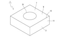
- FIG. 1 is a perspective view of a non-limiting one-sided coated tool of the present disclosure.
- 2 is a cross-sectional view perpendicular to the surface of the substrate in the coated tool shown in FIG. 1 .
- FIG. 2 is a plan view of the coated tool shown in FIG. 1, corresponding to one field of view.
- FIG. 4 is an enlarged view of region IV shown in FIG. 3 .
- FIG. 1 is a perspective view of a non-limiting one-sided cutting tool of the present disclosure.
- the coated tool 1 may include any component member not shown in each of the drawings referred to.
- the dimensions of the components in each drawing do not faithfully represent the dimensions of the actual components and the dimensional ratios of each component.
- the coated tool 1 may include a base 3 and a coating layer 7 located on a surface 5 of the base 3, as shown in a non-limiting example in Figures 1 and 2.
- the coated tool 1 may also have a cutting tool shape.
- the cutting tool shape may mean a shape that can be used as a cutting tool, and a specific configuration may include a plate shape.
- a cutting insert is shown as a non-limiting example of the coated tool 1. Therefore, the cutting tool shape may be rephrased as an insert shape. Note that the form of the coated tool 1 is not limited to a cutting insert.
- the coated tool 1 may have a rake face 9 and a clearance face 11, as shown in a non-limiting example in FIG. 1.
- the coated tool 1 may also be plate-shaped.
- the coated tool 1 may be square plate-shaped.
- the top surface may be the rake face 9.
- the side surface may be the clearance face 11.
- the shape of the coated tool 1 is not limited to a square plate shape.
- the rake face 9 (top surface) may be triangular, pentagonal, hexagonal, or circular.
- the coated tool 1 is not limited to a specific size.
- the length of one side of the rake face 9 (upper surface) may be set to about 3 to 20 mm.
- the height from the rake face 9 (upper surface) to the surface (lower surface) located opposite the rake face 9 may be set to about 5 to 20 mm.
- the coated tool 1 may have a cutting edge ridge 13 located at the intersection of the rake face 9 and the flank 11.
- the cutting edge ridge 13 may be a portion of the intersection of the rake face 9 and the flank 11 that has been subjected to cutting edge treatment.
- the cutting edge ridge 13 may be located over the entire intersection of the rake face 9 and the flank 11, or may be located over only a portion of this intersection.
- the cutting edge ridge 13 can be used to cut a workpiece when manufacturing a machined product using the coated tool 1.
- the cutting edge ridge 13 may also be referred to as a cutting edge.
- the coating layer 7 may include a Ti-based coating layer 15 (titanium-based coating layer) and an Al 2 O 3 layer 17 (alumina layer), as a non-limiting example shown in FIG.
- the Ti-based coating layer 15 may be in contact with the substrate 3.
- the Ti-based coating layer 15 may also be called a base layer.
- the Al2O3 layer 17 may be located farther from the substrate 3 than the Ti-based coating layer 15. Also, the Al2O3 layer 17 may be located the furthest from the substrate 3 in the coating layer 7. The Al2O3 layer 17 may include the outermost surface 19 of the coating layer 7. That is, the Al2O3 layer 17 may be the outermost layer.
- the outermost surface 19 may have a plurality of regions 23 surrounded by cracks 21 (see FIG. 3). In addition to the rake face 9, the outermost surface 19 may also have a plurality of regions 23 on the flank face 11 and/or cutting edge ridge 13. The presence of a plurality of regions 23 on the outermost surface 19 may be confirmed, for example, by observing the outermost surface 19 using a metallurgical microscope.
- the region 23 may be composed of a plurality of cracks 21.
- the cracks 21 may open on the outermost surface 19 (see Figures 2 and 4).
- the cracks 21 may also be referred to as fissures.
- the number of regions 23 in one visual field may be 25 to 60.
- the average area of the regions 23 in one visual field may be 2500 to 4500 ⁇ m2. In this way, when many regions 23 with small average areas are present on the outermost surface 19 at least on the rake face 9, the toughness of the coating layer 7 (Al 2 O 3 layer 17) is likely to be improved. Therefore, the coated tool 1 has high wear resistance.
- One field of view may refer to one field of view in a metallurgical microscope. More specifically, one field of view may refer to a range of 311 ⁇ m ⁇ 411 ⁇ m in a micrograph obtained by photographing the outermost surface 19 at a magnification of 200 times using a metallurgical microscope. Furthermore, multiple locations may be photographed. In this case, the number of regions 23 may be an average value. The number of locations photographed may be, for example, three.
- the crack 21 may extend from the outermost surface 19 toward the substrate 3, as in the non-limiting example shown in FIG. 2.
- the coating layer 7 may have a crack 21 extending from the outermost surface 19 toward the substrate 3.
- the coating layer 7 may have multiple cracks 21.
- the orientation strength of the Al2O3 layer 17 may be 90% or more.
- the number of the regions 23 may be 30 or more. The higher the orientation strength of the Al2O3 layer 17, the more likely the number of cracks 21 will be, and the more likely the number of the regions 23 will be. When the orientation strength of the Al2O3 layer 17 is 90% or more, the number of the regions 23 may be 45 or less.
- the upper limit of the orientation strength of the Al2O3 layer 17 is not limited to a specific value. For example, the orientation strength of the Al2O3 layer 17 may be 98% or less.
- the orientation strength of the Al2O3 layer 17 may be 93% or more.
- the number of the regions 23 may be 40 or more.
- the average area of the regions 23 may be 2500 to 3300 ⁇ m2 . In these cases, the wear resistance is easily improved.
- the orientation strength of the Al 2 O 3 layer 17 may be measured by an electron backscatter diffraction (EBSD) method.
- EBSD electron backscatter diffraction
- the substrate 3 may be a sintered alloy.
- the sintered alloy may be made of a cemented carbide.
- the substrate 3 may be made of a cemented carbide.
- the cemented carbide may contain a hard phase and a binder phase.
- the hard phase in the cemented carbide may contain, for example, tungsten carbide (WC).
- the hard phase in the cemented carbide may contain WC as the main component.
- the cemented carbide may be a WC-based cemented carbide.
- the "main component” may mean the component with the largest mass percentage value compared to other components.
- the binder phase in the cemented carbide may contain an iron group metal.
- iron group metals include cobalt (Co).
- the binder phase in the cemented carbide may contain an iron group metal as a main component.
- the binder phase may function as a phase that bonds adjacent hard phases.
- the substrate 3 may be made of a cemented carbide.
- the hard phase may be made of WC.
- the hard phase may contain a cubic crystal structure compound in addition to WC.
- the cubic crystal structure compound may be composed of at least one selected from carbides, nitrides, carbonates, oxynitrides, and mutual solid solutions of elements in Groups 4, 5, and 6 of the periodic table.
- the hard phase may be composed of WC and at least one cubic crystal structure compound selected from carbides, nitrides, carbonates, oxynitrides, and mutual solid solutions of elements in Groups 4, 5, and 6 of the periodic table.
- the binder phase may be mainly composed of Co.
- the composition of the substrate 3 may be measured, for example, by Energy Dispersive X-ray Spectroscopy (EDS).
- EDS Energy Dispersive X-ray Spectroscopy
- the measurement may be performed using an EDS attached to an electron microscope.
- electron microscopes include a Scanning Electron Microscopy (SEM) and a Transmission Electron Microscopy (TEM).
- the Ti-based coating layer 15 may be a single layer.
- the composition of the Ti-based coating layer 15 may be, for example, TiN.
- the Ti-based coating layer 15 may be a TiN layer.
- the coating layer 7 is not limited to a specific thickness.
- the Ti-based coating layer 15 may have an average thickness of 0.1 to 1 ⁇ m
- the Al 2 O 3 layer 17 may have an average thickness of 1 to 15 ⁇ m.
- the average thickness of the coating layer 7 may be measured by cross-sectional observation using an electron microscope. Specifically, the average thickness of the coating layer 7 may be a value measured under the conditions that the measurement range is a 40 ⁇ m x 50 ⁇ m range in a micrograph obtained by taking a cross-section perpendicular to the surface 5 of the substrate 3 using an electron microscope at a magnification of 3000 times, the thickness of the measurement object such as the Ti-based coating layer 15 is measured at five measurement points at 5 ⁇ m intervals along a direction perpendicular to the thickness direction of the coating layer 7, and the number of photographed points is three. It is not necessary to measure the average thickness of the coating layer 7 at multiple cross-sections, and it is sufficient to measure it at one cross-section.
- the coating layer 7 may have, in order from the substrate 3, a Ti-based coating layer 15, a first TiCN layer 25, a second TiCN layer 27, a TiCNO layer 29 (titanium carbonate nitride layer), and an Al2O3 layer 17. In this case, the life of the coated tool 1 is likely to be long.
- the first TiCN layer 25 may be a so-called MT (moderate temperature)-TiCN layer.
- the first TiCN layer 25 may have an average thickness of 2 to 15 ⁇ m. In this case, the first TiCN layer 25 has high wear resistance and chipping resistance.
- the titanium carbonitride crystals contained in the first TiCN layer 25 may be columnar crystals that are elongated in the thickness direction of the coating layer 7.
- the first TiCN layer 25 may be in contact with the Ti-based coating layer 15.
- the second TiCN layer 27 may be a so-called HT (high temperature)-TiCN layer.
- the second TiCN layer 27 may have an average thickness set to 10 to 900 nm.
- the second TiCN layer 27 may be in contact with the first TiCN layer 25.
- the TiCNO layer 29 may have an average thickness of 200 to 2000 nm, which is likely to improve adhesion to the Al 2 O 3 layer 17.
- the TiCNO layer 29 may be in contact with the second TiCN layer 27.
- the average thickness of the Al 2 O 3 layer 17 may be greater than the average thickness of the TiCNO layer 29.
- the Al 2 O 3 layer 17 may be in contact with the TiCNO layer 29.
- the coating layer 7 may be located on the entire surface 5 of the substrate 3, or on only a portion of the surface 5. In other words, the coating layer 7 may be located on at least a portion of the surface 5 of the substrate 3 (at least the portion corresponding to the rake surface 9).
- the coating layer 7 may be formed by a chemical vapor deposition (CVD) method.
- the coating layer 7 may be a CVD film.
- the coated tool 1 may have a through hole 31.
- the through hole 31 can be used to attach a screw or a clamp member when fixing the coated tool 1 to a holder.
- the through hole 31 may be formed from the scooping face 9 (upper face) to the face (lower face) located opposite the scooping face 9, and may open in these faces. There is no problem with the through hole 31 being configured to open in opposing areas of the relief face 11 (side face).
- a substrate When manufacturing a coated tool, a substrate may be prepared first. An example will be described in which a substrate made of sintered alloy (carbide alloy) is prepared as the substrate.
- a mixed powder may be obtained by adding metal powder, carbon powder, etc. to inorganic powder such as carbide, nitride, carbonitride, or oxide that can form a substrate by firing, and mixing them.
- this mixed powder may be molded into a predetermined cutting tool shape by a known molding method such as press molding, casting molding, extrusion molding, or cold isostatic pressing.
- the obtained molded body may then be fired in a vacuum or a non-oxidizing atmosphere to obtain a substrate made of sintered alloy (carbide alloy).
- a coating layer may be formed on the surface of the obtained substrate by a CVD method.
- the coating layer has, in order from the substrate, a Ti-based coating layer, a first TiCN layer (MT-TiCN layer), a second TiCN layer (HT-TiCN layer), a TiCNO layer, and an Al2O3 layer, and the respective film formation conditions will be described in order.
- a mixed gas containing 0.5 to 10 volume % titanium tetrachloride (TiCl 4 ) gas, 10 to 60 volume % nitrogen (N 2 ) gas, and the remainder hydrogen (H 2 ) gas may be prepared as the reactive gas composition. Then, this mixed gas may be introduced into the chamber, and the film formation temperature may be set to 800 to 900° C. and the pressure may be set to 8 to 50 kPa to form the TiN layer.
- the first TiCN layer may be formed as follows. First, a mixed gas containing 0.5 to 10 volume % titanium tetrachloride (TiCl 4 ) gas, 5 to 60 volume % nitrogen (N 2 ) gas, 0.1 to 3 volume % acetonitrile (CH 3 CN) gas, and the remainder hydrogen (H 2 ) gas may be adjusted as the reaction gas composition. Then, this mixed gas may be introduced into a chamber, and the film formation temperature may be set to a relatively low temperature of 800 to 900° C., and the pressure may be set to 5 to 25 kPa to form the first TiCN layer.
- TiCl 4 titanium tetrachloride
- N 2 nitrogen
- CH 3 CN 0.1 to 3 volume % % acetonitrile
- H 2 hydrogen
- the average crystal width of the titanium carbonitride columnar crystals constituting the first TiCN layer is likely to be larger on the outermost surface side than on the substrate side.
- the second TiCN layer (HT-TiCN layer) may be formed as follows. First, a mixed gas containing 1 to 4 volume % titanium tetrachloride (TiCl 4 ) gas, 5 to 20 volume % nitrogen (N 2 ) gas, 0.1 to 10 volume % methane (CH 4 ) gas, and the remainder hydrogen (H 2 ) gas may be prepared as a reaction gas composition. Then, this mixed gas may be introduced into a chamber, and the film formation temperature may be set to 900 to 1010° C. and the pressure may be set to 5 to 40 kPa to form the second TiCN layer. The second TiCN layer may be formed at a higher temperature than the first TiCN layer.
- TiCl 4 titanium tetrachloride
- N 2 nitrogen
- CH 4 0.1 to 10 volume % methane
- H 2 hydrogen
- the TiCNO layer may be formed as follows. First, a mixed gas containing 3 to 15 volume percent titanium tetrachloride (TiCl 4 ) gas, 3 to 50 volume percent nitrogen (N 2 ) gas, 0.5 to 15 volume percent methane (CH 4 ) gas, 0.5 to 10 volume percent carbon monoxide (CO) gas, and the remainder hydrogen (H 2 ) gas may be prepared as the reaction gas composition. Then, this mixed gas may be introduced into a chamber, and the film formation temperature may be set to 900 to 1010° C. and the pressure may be set to 5 to 40 kPa to form the TiCNO layer.
- TiCl 4 titanium tetrachloride
- N 2 nitrogen
- CH 4 methane
- CO carbon monoxide
- H 2 hydrogen
- the Al 2 O 3 layer may be formed as follows.
- a mixed gas may be prepared as a reaction gas composition, which is composed of 3.5 to 15 volume % aluminum trichloride (AlCl 3 ) gas, 0.5 to 2.5 volume % hydrogen chloride (HCl) gas, 0.5 to 5 volume % carbon dioxide (CO 2 ) gas, 0.3 to 1 volume % hydrogen sulfide (H 2 S) gas, and the remainder hydrogen (H 2 ) gas.
- AlCl 3 aluminum trichloride
- HCl hydrogen chloride
- CO 2 carbon dioxide
- H 2 S hydrogen sulfide
- this mixed gas may be introduced into a chamber, and the film formation temperature may be set to 900 to 1010° C., and the pressure may be set to 5 to 20 kPa.
- the Al2O3 layer may be formed by setting the gas flow rate of aluminum trichloride ( AlCl3 ) gas to 3 to 5 volume %, the gas flow rate of hydrogen chloride (HCl) gas to 0.7 to 0.9 volume %, the gas flow rate of carbon dioxide ( CO2 ) gas to 4 to 5 volume %, the gas flow rate of hydrogen sulfide ( H2S ) gas to 0.6 to 0.9 volume %, and the gas flow rate of hydrogen ( H2 ) gas to 88 to 93 volume %.
- AlCl3 aluminum trichloride
- H2 hydrogen chloride
- CO2 carbon dioxide
- H2S hydrogen sulfide
- H2S hydrogen sulfide
- the coated layer may be cooled after being formed to obtain a coated tool.
- cracks extending from the outermost surface toward the substrate are likely to be formed in the coating.
- the number of regions in one field of view is likely to be 25 to 60, and the average area of the regions is likely to be 2500 to 4500 ⁇ m 2. This is presumably due to the thermal expansion coefficient of Al 2 O 3 in the highly oriented Al 2 O 3 layer. That is, in Al 2 O 3 , the (0001) plane tends to have a higher tensile residual stress of Al 2 O 3 than the (1012) plane or the (1014) plane.
- coated tools are not limited to those manufactured by the above manufacturing method.
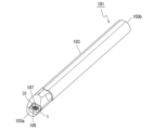
- the cutting tool 101 may include a holder 103 and a coated tool 1, as shown in a non-limiting example in FIG. 5.
- the holder 103 may extend from a first end 103a toward a second end 103b, and may have a pocket 105 on the side of the first end 103a.
- the coated tool 1 may be located in the pocket 105.
- the coated tool 1 has high wear resistance, enabling stable cutting.
- the pocket 105 may be a portion in which the coated tool 1 is attached.
- the pocket 105 may open on the outer peripheral surface of the holder 103 and on the end surface on the side of the first end 103a.
- the coated tool 1 may be attached to the pocket 105 so that at least a part of the cutting edge ridge 13 protrudes from the holder 103.
- the coated tool 1 may also be attached to the pocket 105 by a screw 107. That is, the coated tool 1 may be attached to the pocket 105 by inserting the screw 107 into the through hole 31 of the coated tool 1 and inserting the tip of the screw 107 into a screw hole formed in the pocket 105 to fix the screw 107 in the screw hole.
- the bottom surface of the coated tool 1 may be in direct contact with the pocket 105, or a sheet may be sandwiched between the coated tool 1 and the pocket 105.
- the material of the holder 103 may be, for example, steel or cast iron. If the material of the holder 103 is steel, the holder 103 has high toughness.
- a cutting tool 101 used for so-called turning is illustrated.
- Examples of turning include internal diameter machining, external diameter machining, and groove machining.
- the cutting tool 101 (coated tool 1) is not limited to use for turning. For example, there is no problem in using the coated tool 1 for the cutting tool 101 used for milling.
- the coated tool 1 and the cutting tool 101 may have the following configuration.
- the substrate may be a sintered alloy made of a cemented carbide containing a hard phase and a binder phase.
- the substrate may be made of a cemented carbide containing a hard phase and a binder phase
- the hard phase may be made of tungsten carbide or tungsten carbide and at least one cubic crystal structure compound selected from carbides, nitrides, carbonates, oxynitrides of elements in Groups 4, 5 and 6 of the Periodic Table and their mutual solid solutions
- the binder phase may be mainly composed of cobalt.
- the coating layer may have, in order from the base, the Ti-based coating layer, a first TiCN layer, a second TiCN layer, a TiCNO layer and the Al 2 O 3 layer.
- the cutting tool may include a holder extending from a first end toward a second end and having a pocket on the side of the first end, and a coated tool according to any one of (1) to (5) above, located in the pocket.
- a substrate was prepared. Specifically, 6 mass% of metal cobalt powder with an average particle size of 1.2 ⁇ m, 0.5 mass% of titanium carbide powder with an average particle size of 2 ⁇ m, 5 mass% of niobium carbide powder with an average particle size of 2 ⁇ m, and the remainder of the powder with an average particle size of 1.5 ⁇ m were mixed to obtain a mixed powder. The average particle size of each powder was measured by a microtrack method.
- the obtained mixed powder was press-molded into a cutting tool shape (CNMG120408) to obtain a molded body.
- the obtained molded body was then subjected to a binder removal process and then sintered in a non-oxidizing atmosphere to obtain a base body made of cemented carbide.
- the sintering temperature was set to 1450°C
- the sintering time was set to 1 hour
- an argon atmosphere was used as the non-oxidizing atmosphere.
- the composition of the obtained cemented carbide was measured by EDS. Specifically, cross-sections were observed using an EDS attached to an SEM at a magnification of 5,000 to 20,000 times, and the average value of measurements at five locations was measured. Five elements were selected for measurement using EDS: tungsten carbide, cobalt, titanium, carbon, and nitrogen.
- the obtained cemented carbide contained a hard phase and a binder phase. More specifically, the obtained cemented carbide contained a hard phase made of WC and a binder phase mainly composed of Co.
- a Ti-based coating layer was first formed on the surface of the substrate, and then a first TiCN layer (MT-TiCN layer), a second TiCN layer (HT-TiCN layer), a TiCNO layer, and an Al2O3 layer were formed in this order on the Ti-based coating layer.
- the respective film formation conditions were as follows:
- Ti-based coating layer A single layer of TiN was formed as the Ti-based coating layer.
- a mixed gas consisting of 1 volume % titanium tetrachloride (TiCl 4 ) gas, 38 volume % nitrogen (N 2 ) gas, and the remainder hydrogen (H 2 ) gas was prepared as the reaction gas composition. Then, this mixed gas was introduced into the chamber, and the film formation temperature was set to 850° C. and the pressure was set to 18 kPa. The film formation time was set to 180 minutes.
- a mixed gas was prepared as a reactive gas composition, which consisted of 4 volume % titanium tetrachloride ( TiCl4 ) gas, 20 volume % nitrogen ( N2 ) gas, 8 volume % methane ( CH4 ) gas, 2 volume % carbon monoxide (CO) gas, and the remainder hydrogen ( H2 ) gas.
- TiCl4 titanium tetrachloride
- N2 nitrogen
- CH4 methane
- CO carbon monoxide
- H2 hydrogen
- a mixed gas was prepared as a reaction gas composition, which consisted of 3.7 volume % aluminum trichloride ( AlCl3 ) gas, 0.7 volume % hydrogen chloride (HCl) gas, 4.3 volume % carbon dioxide ( CO2 ) gas, 0.3 volume % hydrogen sulfide ( H2S ) gas, and the remainder hydrogen ( H2 ) gas.
- This mixed gas was then introduced into the chamber, and the film formation temperature, pressure, and gas flow rate were set to the conditions shown in Table 1. The film formation time was set to 300 minutes.
- the number of regions in one visual field and the average area of the regions in one visual field were measured according to the method exemplified above. Specifically, one visual field was defined as an area of 311 ⁇ m ⁇ 411 ⁇ m in a micrograph obtained by photographing the outermost surface of the rake face at a magnification of 200 times using a metallurgical microscope. Three photographs were taken. The measurement results are shown in the "Number (pieces)" and “Average area ( ⁇ m2 )" columns in the "Region” section of Table 2. The number of regions is an average value.
- the orientation strength of the Al 2 O 3 layer was measured by the EBSD method. Specifically, the measurement range was a 60 ⁇ m cross-sectional polished surface in a direction parallel to the surface of the substrate. A sample was set in the lens barrel of a field emission SEM, and an electron beam with an accelerating voltage of 25 kV was irradiated to each crystal grain having a hexagonal crystal lattice present within the measurement range of the polished surface at an incidence angle of 70 degrees to the polished surface.
- the tilt angle of the normal of the (0001 ) plane, which is the crystal face of the crystal grain, to the normal of the surface of the substrate was measured in the range of 0 to 45 degrees at intervals of 0.1 ⁇ m/step for the Al 2 O 3 crystal grains.
- the measurement results were represented by a tilt angle number distribution graph obtained by tallying up the frequency present in each division. Based on this measurement result, the total frequency of crystal grains (interface orientation form Al 2 O 3 crystal grains) with measured tilt angles of 0 to 15 degrees was measured to determine the orientation strength of the Al 2 O 3 layer.
- Table 2 The measurement results are shown in Table 2.
- Samples No. 1 to 3 showed higher abrasion resistance than samples No. 4 to 5.
- samples No. 1 to 5 there were multiple regions on the outermost surface even on the flank and cutting edge ridge.
- the same measurements were carried out on the flank and cutting edge ridge of samples No. 1 to 5 as on the rake face.
- the measurement results for the flank and cutting edge ridge of samples No. 1 to 5 were essentially the same as those for the rake face.
- Coated tool 3 Base body 5: Surface 7: Coating layer 9: Rake face (upper surface) 11...Flank face (side face) Reference Signs List 13: Cutting edge ridge 15: Ti-based coating layer 17: Al2O3 layer 19 : Outermost surface 21: Crack 23: Region 25: First TiCN layer 27: Second TiCN layer 29: TiCNO layer 31: Through hole 101: Cutting tool 103: Holder 103a: First end 103b: Second end 105: Pocket 107: Screw
Landscapes
- Chemical & Material Sciences (AREA)
- Engineering & Computer Science (AREA)
- Mechanical Engineering (AREA)
- Inorganic Chemistry (AREA)
- General Chemical & Material Sciences (AREA)
- Chemical Kinetics & Catalysis (AREA)
- Materials Engineering (AREA)
- Metallurgy (AREA)
- Organic Chemistry (AREA)
- Cutting Tools, Boring Holders, And Turrets (AREA)
- Chemical Vapour Deposition (AREA)
Priority Applications (1)
| Application Number | Priority Date | Filing Date | Title |
|---|---|---|---|
| JP2025523373A JPWO2024247600A1 (https=) | 2023-05-26 | 2024-05-01 |
Applications Claiming Priority (2)
| Application Number | Priority Date | Filing Date | Title |
|---|---|---|---|
| JP2023086790 | 2023-05-26 | ||
| JP2023-086790 | 2023-05-26 |
Publications (1)
| Publication Number | Publication Date |
|---|---|
| WO2024247600A1 true WO2024247600A1 (ja) | 2024-12-05 |
Family
ID=93657366
Family Applications (1)
| Application Number | Title | Priority Date | Filing Date |
|---|---|---|---|
| PCT/JP2024/016807 Ceased WO2024247600A1 (ja) | 2023-05-26 | 2024-05-01 | 被覆工具及び切削工具 |
Country Status (2)
| Country | Link |
|---|---|
| JP (1) | JPWO2024247600A1 (https=) |
| WO (1) | WO2024247600A1 (https=) |
Citations (2)
| Publication number | Priority date | Publication date | Assignee | Title |
|---|---|---|---|---|
| US5123934A (en) * | 1989-09-04 | 1992-06-23 | Nippon Steel Corporation | Ceramics coated cemented-carbide tool with high-fracture resistance |
| JP2017071045A (ja) * | 2016-02-24 | 2017-04-13 | 住友電工ハードメタル株式会社 | 表面被覆切削工具およびその製造方法 |
-
2024
- 2024-05-01 JP JP2025523373A patent/JPWO2024247600A1/ja active Pending
- 2024-05-01 WO PCT/JP2024/016807 patent/WO2024247600A1/ja not_active Ceased
Patent Citations (2)
| Publication number | Priority date | Publication date | Assignee | Title |
|---|---|---|---|---|
| US5123934A (en) * | 1989-09-04 | 1992-06-23 | Nippon Steel Corporation | Ceramics coated cemented-carbide tool with high-fracture resistance |
| JP2017071045A (ja) * | 2016-02-24 | 2017-04-13 | 住友電工ハードメタル株式会社 | 表面被覆切削工具およびその製造方法 |
Also Published As
| Publication number | Publication date |
|---|---|
| JPWO2024247600A1 (https=) | 2024-12-05 |
Similar Documents
| Publication | Publication Date | Title |
|---|---|---|
| JP6608937B2 (ja) | 被覆工具 | |
| KR102320077B1 (ko) | 표면 피복 절삭 공구 및 그 제조 방법 | |
| CN101790594A (zh) | Ti基金属陶瓷及被覆金属陶瓷以及切削工具 | |
| KR102312226B1 (ko) | 표면 피복 절삭 공구 및 그 제조 방법 | |
| US11123802B2 (en) | Surface-coated cutting tool and method for manufacturing the same | |
| US11020804B2 (en) | Surface-coated cutting tool and method for manufacturing the same | |
| US20200061716A1 (en) | Surface-Coated Cutting Tool and Method for Manufacturing the Same | |
| JP7851394B2 (ja) | 超硬合金およびこれを用いた被覆工具、切削工具 | |
| WO2024247600A1 (ja) | 被覆工具及び切削工具 | |
| WO2024247604A1 (ja) | 被覆工具及び切削工具 | |
| JP7851412B2 (ja) | 被覆工具および切削工具 | |
| JP7791317B2 (ja) | 被覆工具および切削工具 | |
| WO2024181014A1 (ja) | 被覆工具及び切削工具 | |
| JP7805459B2 (ja) | 被覆工具および切削工具 | |
| WO2025192090A1 (ja) | 被覆工具及び切削工具 | |
| JP7566153B2 (ja) | 被覆工具 | |
| JP7750434B1 (ja) | 切削工具 | |
| WO2026083717A1 (ja) | 被覆工具及び切削工具 | |
| KR102739604B1 (ko) | 피복 공구 | |
| JPWO2019146786A1 (ja) | 被覆工具およびこれを備えた切削工具 | |
| WO2025192092A1 (ja) | 超硬合金、被覆工具及び切削工具 | |
| WO2025192091A1 (ja) | 被覆工具及び切削工具 | |
| WO2025197502A1 (ja) | 被覆工具及び切削工具 | |
| WO2024181015A1 (ja) | 超硬合金、被覆工具及び切削工具 | |
| US11839923B2 (en) | Coated tool, cutting tool, and method for manufacturing machined product |
Legal Events
| Date | Code | Title | Description |
|---|---|---|---|
| 121 | Ep: the epo has been informed by wipo that ep was designated in this application |
Ref document number: 24815084 Country of ref document: EP Kind code of ref document: A1 |
|
| ENP | Entry into the national phase |
Ref document number: 2025523373 Country of ref document: JP Kind code of ref document: A |
|
| NENP | Non-entry into the national phase |
Ref country code: DE |