WO2024247411A1 - 電磁波反射装置、電磁波反射フェンス、及び電磁波反射パネルの設置方法 - Google Patents
電磁波反射装置、電磁波反射フェンス、及び電磁波反射パネルの設置方法 Download PDFInfo
- Publication number
- WO2024247411A1 WO2024247411A1 PCT/JP2024/007266 JP2024007266W WO2024247411A1 WO 2024247411 A1 WO2024247411 A1 WO 2024247411A1 JP 2024007266 W JP2024007266 W JP 2024007266W WO 2024247411 A1 WO2024247411 A1 WO 2024247411A1
- Authority
- WO
- WIPO (PCT)
- Prior art keywords
- electromagnetic wave
- panel
- frame
- curvature
- wave reflection
- Prior art date
- Legal status (The legal status is an assumption and is not a legal conclusion. Google has not performed a legal analysis and makes no representation as to the accuracy of the status listed.)
- Ceased
Links
Images




Classifications
-
- H—ELECTRICITY
- H01—ELECTRIC ELEMENTS
- H01Q—ANTENNAS, i.e. RADIO AERIALS
- H01Q15/00—Devices for reflection, refraction, diffraction or polarisation of waves radiated from an antenna, e.g. quasi-optical devices
- H01Q15/14—Reflecting surfaces; Equivalent structures
Definitions
- the present invention relates to a method for installing an electromagnetic wave reflecting device, an electromagnetic wave reflecting fence, and an electromagnetic wave reflecting panel.
- Base stations are being installed in indoor and outdoor facilities to realize various use cases, such as automation of manufacturing processes and office work, remote operation, introduction of control and management using AI (Artificial Intelligence), and autonomous driving.
- Indoor and outdoor facilities include factories, plants, offices, commercial facilities, medical sites, event venues, highways, and railway tracks.
- the fifth generation mobile communication system (hereinafter referred to as "5G") provides a frequency band of 6 GHz or less called “sub-6" and a 28 GHz band classified as a millimeter wave band.
- the next generation 6G mobile communication standard is expected to expand to the terahertz band. By using such high frequency bands, the communication bandwidth will be expanded, enabling large amounts of data communication with low latency.
- a configuration has been proposed in which electromagnetic wave reflecting devices are arranged along at least a part of a production line (see, for example, Patent Document 1).
- Reflective panels include regular reflection panels that reflect incident electromagnetic waves at the same angle as the angle of incidence, and panels with metasurfaces, which are artificial reflective surfaces with controlled reflection and diffusion. In either case, the width of the reflected beam is narrow, making it difficult to reflect electromagnetic waves over a wide area of space. In order to deliver electromagnetic waves over a wide area, it may be necessary to increase the number of reflective panels installed.
- One object of the present invention is to provide an electromagnetic wave reflection device that expands the reflected beam width of an incident electromagnetic wave.
- the electromagnetic wave reflecting device comprises: an electromagnetic wave reflection panel that reflects electromagnetic waves in a predetermined frequency band of 1 GHz or more and 300 GHz or less; A frame for holding the electromagnetic wave reflecting panel; The electromagnetic wave reflective panel is curved with a predetermined radius of curvature so as to be convex in a direction in which the incident electromagnetic wave is reflected and is held by the frame.
- An electromagnetic wave reflection device is realized that expands the reflected beam width of incident electromagnetic waves.
- FIG. 1 is a schematic diagram showing an installation state of an electromagnetic wave reflecting device according to an embodiment
- 4 is a schematic diagram showing another installation mode of the electromagnetic wave reflecting device of FIG. 1.
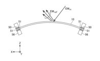
- 1 is a schematic diagram showing incidence and reflection of electromagnetic waves on a curved electromagnetic wave reflecting panel.
- 1 is a schematic top view of an electromagnetic wave reflective fence made up of multiple connected electromagnetic wave reflective panels.
- FIG. 2 is a diagram showing an example of a layer structure of an electromagnetic wave reflecting panel.
- 4 is a schematic diagram showing an example of the configuration of a frame and legs that hold an electromagnetic wave reflecting panel.
- FIG. FIG. 7 is a schematic diagram of an electromagnetic wave reflecting device using the frame and legs of FIG. 6.
- FIG. 13 is a diagram showing a modified example of the frame.
- FIG. 13 is a diagram showing another modified example of the frame.
- a flexible transparent substrate such as resin is used for the electromagnetic wave reflection panel, and the electromagnetic wave reflection panel is curved so that it is convex in the direction in which the electromagnetic wave is to be reflected. Electromagnetic waves that are incident on the convex curved surface are reflected over a wide area of space.
- FIG. 1 is a schematic diagram showing the installation state of an electromagnetic wave reflecting device 60 of an embodiment.
- the electromagnetic wave reflecting device 60 has an electromagnetic wave reflecting panel 10 and a frame 50 that holds the electromagnetic wave reflecting panel 10.
- the width or horizontal direction of the electromagnetic wave reflecting panel 10 is the X direction
- the height or vertical direction is the Y direction
- the thickness direction is the Z direction.
- the electromagnetic wave reflecting panel 10 is held by the frame 50 so that it is curved convexly in the direction in which the electromagnetic wave is to be reflected. This allows the electromagnetic wave EMin of the desired frequency band incident on the electromagnetic wave reflecting panel 10 to be reflected over a wider angular range than a flat regular reflecting surface or metasurface, expanding the beam width of the reflected electromagnetic wave EMref. By expanding the beam width, the spatial range covered by the reflected electromagnetic wave EMref is expanded.
- the beam width of the reflected electromagnetic wave EMref is expressed as the angle between two points where the gain drops by 3 dB from the direction where the power reflection efficiency is at its peak, and is also called the 3 dB beam width or 1/2 power beam width.
- the electromagnetic wave reflection panel 10 is curved within a range that does not damage it, and the reflected beam width is expanded.
- the reflected beam width of a flat regular reflection surface or metasurface is about 3°, and at most less than 5°.
- the electromagnetic wave reflection panel 10 has the sides in the width direction parallel to the XZ plane, which is the installation surface, curved into an arc shape, and both ends in the height direction are held by the frame 50.
- the electromagnetic wave reflection panel 10 has a width of 1 m and a thickness of 5.0 mm, the radius of curvature of the electromagnetic wave reflection panel 10 in the XZ plane is greater than 350 mm and less than 2000 mm.
- the flexibility of the electromagnetic wave reflecting panel 10 is limited, and it is desirable to curve the electromagnetic wave reflecting panel 10 within a range in which the electromagnetic wave reflecting panel 10 can be stably held by the frame 50 without being damaged. If the radius of curvature is set to 0.070 times or less the product of the side of the electromagnetic wave reflecting panel 10 that is curved into an arc (the width in the example of FIG.
- the curvature becomes too strong, and the electromagnetic wave reflecting panel 10 may be damaged or may not be held stably. If the radius of curvature is set to 0.4 times or more the product of the side of the electromagnetic wave reflecting panel 10 that is curved into an arc and the panel thickness, the curvature becomes too small, making it difficult to effectively expand the beam width of the reflected electromagnetic wave EMref.
- the electromagnetic wave reflection panel 10 reflects electromagnetic waves in a predetermined frequency band of 1 GHz to 300 GHz. Electromagnetic waves in this range include microwaves, millimeter waves, and submillimeter waves.
- the electromagnetic wave reflection panel 10 has a reflection function layer that reflects electromagnetic waves in the above frequency band.
- the reflection function layer may include a conductive layer that forms a regular reflection surface, or a conductive layer that forms a metasurface with controlled reflection or diffusion.
- the conductive layer may be formed of a good conductor such as Ag, Cu, Ni, Al, or Pd, or a transparent metal oxide conductor, and may be processed into a periodic pattern, mesh pattern, geometric pattern, or the like.
- the electromagnetic wave reflection panel 10 has a visible light transmittance of 70% or more, preferably 80% or more, and more preferably 90% or more.
- the reflective functional layer of the electromagnetic wave reflecting panel 10 is supported on a flexible dielectric substrate, as described below.
- the flexible substrate is formed of a transparent, heat-resistant resin material, such as polyethylene terephthalate (PET), polycarbonate (PC), cycloolefin polymer (COP), polyimide (PI), or fluororesin.
- PET polyethylene terephthalate
- PC polycarbonate
- COP cycloolefin polymer
- PI polyimide
- fluororesin fluororesin.
- the thickness of the flexible substrate is appropriately selected in the range of 1.0 mm or more and 5.0 mm or less so that the electromagnetic wave reflecting panel 10 can be curved with the desired radius of curvature.
- the electromagnetic wave reflecting panel 10 and the frame 50 are removable and may be transported separately to the installation site and assembled there.
- the electromagnetic wave reflecting panel 10 may be a flat panel when removed from the frame 50. Since the entire electromagnetic wave reflecting panel 10 is flexible, the panel surface can be curved with a predetermined radius of curvature by changing the position or spacing of the frame 50 that holds the electromagnetic wave reflecting panel 10.
- the electromagnetic wave reflecting device 60 may be provided with legs 56 that support the frame 50. Although the legs 56 are not essential, providing the legs 56 allows the frame 50 to be stably supported and the electromagnetic wave reflecting device 60 to stand on its own.
- the electromagnetic wave reflecting panel 10 may be installed along a curved wall surface or pillar without providing the frame 50 or legs 56.
- the frame 50 may be formed as thin as possible to minimize the difference in thickness with the electromagnetic wave reflecting panel 10, and the frame 50 may be fixed to the wall surface with screws or the like.
- the frame 50 may be fixed to the legs 56, or may be supported so as to be rotatable around the Y axis, as described below. In the example of FIG. 1, the frame 50 is fixed to the legs 56.
- the orientation and spacing of the two legs 56 supporting the frame 50 vary depending on the degree of curvature of the electromagnetic wave reflecting panel 10.
- the legs 56 may be fixed with screws to the floor surface, ground, etc. on which the electromagnetic wave reflecting device 60 is installed, as necessary.
- FIG. 2 shows another installation mode of the electromagnetic wave reflecting device of FIG. 1.
- the electromagnetic wave reflecting panel 10 is manufactured as a flat panel, in a site where there is little demand for expanding the reflected beam width, it can be used as an electromagnetic wave reflecting device 60 having a flat surface as shown in FIG. 2.
- the electromagnetic wave reflecting panel 10 can be installed in the manner shown in FIG. 2.
- the upper and lower ends of the electromagnetic wave reflecting panel 10 may be held by a top frame 57 and a bottom frame 58, respectively.
- the frame 50, the top frame 57, and the bottom frame 58 form a frame that holds the entire circumference of the electromagnetic wave reflecting panel 10.
- the frame 50 may be called a "side frame" based on its positional relationship with the top frame 57 and the bottom frame 58.
- the electromagnetic wave reflection device 60 installed in the manner shown in FIG. 2 can be curved as shown in FIG. 1 for use.
- the beam width of the reflected electromagnetic wave EMref can be expanded.
- FIG. 3 is a schematic diagram showing the incidence and reflection of electromagnetic waves on a curved electromagnetic wave reflecting panel 10. Both ends of the electromagnetic wave reflecting panel 10 are inserted into slits 51 in a frame 50 and are held so that they have a predetermined radius of curvature in the XZ plane. The radius of curvature of the electromagnetic wave reflecting panel 10 in the XZ plane can be changed by adjusting the position or spacing of the frame 50.
- an incident electromagnetic wave EMin of a target frequency band for example, the 28 GHz band
- hits the curved electromagnetic wave reflecting panel 10 it is most strongly reflected and dispersed in the direction of regular reflection in the case of a specular reflecting surface, and in the direction controlled by the design in the case of a metasurface.
- a receiving antenna located within the area covered by the reflected electromagnetic wave EMref receives radio waves in the target frequency band.
- FIG. 4 is a schematic top view of an electromagnetic wave reflecting fence 100 in which electromagnetic wave reflecting panels 10-1 and 10-2 are connected by a frame 50.
- the electromagnetic wave reflecting panels 10-1 and 10-2 are connected by inserting the adjacent ends of the electromagnetic wave reflecting panels 10-1 and 10-2 into a pair of slits 51 provided in the frame 50.
- the required number of electromagnetic wave reflecting panels 10 can be connected using the frame 50. It is not necessary to curve all of the electromagnetic wave reflecting panels 10 to be connected, and at least one electromagnetic wave reflecting panel 10 may be curved.
- An electromagnetic wave reflecting panel 10 held flat and an electromagnetic wave reflecting panel 10 held curved may be connected, or two or more electromagnetic wave reflecting panels 10 may be connected with different radii of curvature.
- the electromagnetic wave reflective panel is used with its widthwise edges curved, but it may also be installed at a high position on a ceiling or wall by curving its heightwise edges.
- the electromagnetic wave reflective panel may be held at its upper and lower ends by a top frame 57 and a bottom frame 58, and its vertical edges curved to fix it to a wall or ceiling. In that case, electromagnetic waves incident on the electromagnetic wave reflective panel 10 from below can be reflected downward with a wide beam width.
- ⁇ Layer structure of electromagnetic wave reflection panel> 5 shows an example of the layer structure of the electromagnetic wave reflection panel 10.
- the stacking direction is the thickness direction (Z direction) of the electromagnetic wave reflection panel 10A.
- the reflection function layer 15 is adhered and held between the flexible substrates 11 and 12 by the adhesive layers 13 and 14.
- the flexible substrates 11 and 12 are transparent to electromagnetic waves from the gigahertz band to the terahertz band, specifically, electromagnetic waves from 1 GHz to 300 GHz. In the example of FIG. 5, two flexible substrates are used, but the reflection function layer 15 may be held by using only one of the flexible substrates 11 and 12.
- the flexible substrates 11 and 12 may be the outermost layers of the electromagnetic wave reflecting panel 10 and may have impact resistance and durability.
- the flexible substrates 11 and 12 may be made of polycarbonate, PET, COP, PI, resin with poor optical properties, fluororesin, etc.
- the thickness of the flexible substrates 11 and 12 is appropriately determined within a range that does not impede the flexibility of the electromagnetic wave reflecting panel 10, for example, between 1.0 mm and 5.0 mm.
- the thickness of the flexible substrates 11 and 12 may be the same or different.
- the adhesive layers 13 and 14 may be a general non-carrier (base material-free) pressure sensitive adhesive or a silicone adhesive.
- Thermoplastic resins such as vinyl acetate resin, acrylic resin, cellulose resin, and silicone resin may also be used. If it is desired to give durability and moisture resistance to the adhesive layers 13 and 14, ethylene-vinyl acetate (EVA) copolymer or COP may be used.
- the thickness of the adhesive layers 13 and 14 may be any thickness that can bond the reflective function layer 15 to the flexible substrates 11 and 12, and may be appropriately selected, for example, within the range of 10 ⁇ m to 500 ⁇ m.
- the reflective function layer 15 is formed of a good conductor such as Ag, Cu, Al, or Pd, or a transparent metal oxide conductor.
- the reflective function layer 15 may be a flat film that reflects mirror-like, or may be formed with a periodic pattern, a mesh pattern, a geometric pattern, or the like.
- the layer structure of the electromagnetic wave reflection panel 10 does not necessarily have to be symmetrical in the stacking direction with the reflective function layer 15 at the center as shown in FIG. 5.
- the reflective function layer 15 may be covered with a transparent resin film with adhesive.
- the dielectric constant and dielectric loss tangent of the flexible substrates 11 and 12 and the adhesive layers 13 and 14 are appropriately selected for the entire laminate so as to obtain the target reflection characteristics.
- appropriate dielectric constants and dielectric loss tangents are similarly selected for the entire laminate.
- the non-dielectric constant of the dielectric portion excluding the reflective function layer 15 is, for example, 2.0 or more and 3.0 or less, and the dielectric loss tangent is 0.0001 or more and less than 0.1000.
- Flexible materials with a dielectric constant of less than 2.0 are currently difficult to obtain. If the dielectric constant exceeds 3.0, loss increases, especially for high frequencies. The same is true for the dielectric loss tangent.
- Flexible materials with a dielectric loss tangent of less than 0.0001 are difficult to obtain. If the dielectric loss tangent is 0.1000 or more, the loss of electrical energy inside the electromagnetic wave reflection panel 10 increases.
- a flexible substrate 12 is not used and the reflective function layer 15 supported on the flexible substrate 11 via the adhesive layer 13 is covered with a resin film with adhesive, it is preferable to use an electromagnetic wave reflection panel 10 so that electromagnetic waves are incident from the resin film side and reflected. In this case, a mark indicating the incident surface may be formed on the end of the resin film.
- Fig. 6 shows a configuration example of a frame 50A and legs 56A supporting the frame 50A.
- the frame 50 is fixed to the legs 56 to allow the electromagnetic wave reflecting device 60 to stand on its own.
- the frame 50A is supported by the legs 56 so as to be rotatable about a central axis 52.
- the frame 50A has a central axis 52 extending from the lower end of the frame 50A.
- the legs 56A have holes 59 that receive the central axis 52 of the frame 50A. After both ends of the electromagnetic wave reflecting panel 10 are inserted into the slits 51 of the frame 50A, the frame 50A may be rotated around the central axis 52 to fine-tune the direction of the convex surface. After the electromagnetic wave reflecting panel 10 has been curved to the desired radius of curvature and in the desired direction, the legs 56A may be fixed to the installation surface.
- FIG. 7 is a schematic diagram of an electromagnetic wave reflection device 60A using the frame 50A and legs 56A of FIG. 6.
- the pair of legs 56A may be fixed parallel to each other in the XZ plane.
- the direction of the convex can be adjusted to reflect and disperse the incident electromagnetic wave EMin in a desired direction and expand the beam width of the reflected electromagnetic wave EMref.
- FIG. 8 shows a modified example of the frame.
- the frame 50B holds the curved sides of the electromagnetic wave reflection panel 10.
- the horizontal sides of the electromagnetic wave reflection panel 10 are curved, and the frame 50B holds the upper and lower ends of the electromagnetic wave reflection panel 10.
- the frame 50B may be configured with a curved top frame 57 and bottom frame 58, or the electromagnetic wave reflection panel 10 may be configured to support the convex surface that serves as the reflective surface from the back side.
- the main body of the frame 50B may be configured to be curved with a predetermined radius of curvature, and slits for receiving the electromagnetic wave reflection panel 10 may be formed on the surfaces of the main body facing the upper and lower ends of the electromagnetic wave reflection panel 10.
- the electromagnetic wave reflection panel 10 can be curved with a predetermined radius of curvature so as to be convex in the direction in which the electromagnetic waves are to be reflected.
- the frame 50B in FIG. 8 holds the electromagnetic wave reflecting panel 10 with a predetermined radius of curvature.
- the frame 50C of the electromagnetic wave reflecting device 60C in FIG. 9 holds the electromagnetic wave reflecting panel 10 with a variable or adjustable radius of curvature.
- the frame 50C has a pair of holding members 513 that hold both ends of the electromagnetic wave reflecting panel 10 in the lateral direction (X direction), a support link 511 that extends in the X direction between the pair of holding members 53, and a plurality of ribs 512 that protrude from the support link 511 at equal intervals in the thickness direction (Z direction) of the electromagnetic wave reflecting panel 10.
- the holding member 513 may be the frame 50 used as a side frame in FIGS.
- the support link 511 is configured so that the length between each rib 512 can be adjusted.
- the support link 511 may be structured so that the length can be adjusted by expanding and contracting and the state can be maintained.
- Each rib 512 is configured so that its length in the Z direction can be adjusted.
- the lengths of the support link 511 and each rib 512 may be configured so that they are continuously variable, or so that they are variable in stages.
- the support link 511 having multiple ribs 512 may be connected to the holding member 513 near the upper and lower ends of the electromagnetic wave reflecting panel 10 in the height direction (Y direction).
- the support link 511 and ribs 512 may be made of a material having a relative dielectric constant equivalent to that of the flexible substrate 11 or 12 of the electromagnetic wave reflecting panel, and connected to the holding member 513 at or near the center of the electromagnetic wave reflecting panel 10.
- the frame 50C holds the electromagnetic wave reflecting panel 10 with a radius of curvature adjustable within a range greater than 0.070 times and less than 0.4 times the product of the length and thickness of the curved side of the electromagnetic wave reflecting panel 10.
- a sample of the electromagnetic wave reflection panel 10 is produced, and the reflected beam width is calculated by changing the radius of curvature or the installation state of the electromagnetic wave reflection panel.
- a general-purpose three-dimensional electromagnetic field simulation software is used to input a plane wave of 28.0 GHz at an incident angle of 0°, and the scattering cross section is analyzed from the reflected current.
- the scattering cross section is used as an index representing the reflection characteristics.
- the scattering cross section is analyzed, and the beam width is calculated from the reflection angle and the maximum gain (dB).
- the electromagnetic wave reflection panel with the layer structure of FIG. 5 is curved at a side parallel to the XZ plane.
- Example 1 is Example 1.
- two polycarbonate sheets with a length of 2.0 m, a width of 1.0 m, and a thickness of 2.0 mm are prepared and used as flexible substrates 11 and 12.
- a stainless steel mesh with a thickness of 100 ⁇ m is used as the reflection function layer 17, and EVA with a thickness of 450 ⁇ m is used as the adhesive layers 13 and 14, sandwiched between the two polycarbonate sheets and laminated.
- the laminated layer is heated at a temperature of 100° C.
- the sample after the lamination process is curved convexly in the direction to be reflected so that the radius of curvature in the XZ plane parallel to the installation surface is 1000 mm.
- This radius of curvature is 0.2 times the value (1000 mm x 5 mm) obtained by multiplying the length of the curved side of the electromagnetic wave reflection panel, i.e., the width, and the thickness of the laminated sample.
- Analysis of the scattering cross section for a 28.0 GHz plane wave incident at an incidence angle of 0° revealed that the beam width at 3 dB below the maximum gain, i.e., where the intensity is reduced by half, was 7.0°, expanding the reflected beam width beyond the 3° to 5° reflected beam width of a typical regular reflecting surface or metasurface.
- Example 2 is Example 2.
- a sample of an electromagnetic wave reflection panel made with the same configuration and lamination processing as Example 1 is curved convexly in the direction to be reflected so that the radius of curvature in the XZ plane parallel to the installation surface is 360 mm. This radius of curvature is 0.072 times the value (1000 mm x 5 mm) obtained by multiplying the width of the electromagnetic wave reflection panel by the thickness of the laminated sample.
- the scattering cross section when a 28.0 GHz plane wave is incident at an incident angle of 0° was analyzed, the beam width at the point where the gain is 3 dB lower than the maximum gain (the intensity is halved) was expanded to 20.0°.
- Example 3 is Example 3.
- a sample of an electromagnetic wave reflection panel made with the same configuration and lamination processing as Example 1 is curved convexly in the direction to be reflected so that the radius of curvature in the XZ plane parallel to the installation surface is 500 mm. This radius of curvature is 0.1 times the value (1000 mm x 5 mm) obtained by multiplying the width of the electromagnetic wave reflection panel by the thickness of the laminated sample.
- the scattering cross section when a 28.0 GHz plane wave is incident at an incident angle of 0° was analyzed, the beam width at the point where the gain is 3 dB lower than the maximum gain (the intensity is halved) was expanded to 12.5°.
- Example 4 is Example 4.
- a sample of an electromagnetic wave reflection panel made with the same configuration and lamination processing as Example 1 is curved convexly in the direction to be reflected so that the radius of curvature in the XZ plane parallel to the installation surface is 1500 mm.
- This radius of curvature is 0.3 times the value (1000 mm x 5 mm) obtained by multiplying the width of the electromagnetic wave reflection panel by the thickness of the laminated sample. The curvature is small enough that the panel surface appears flat.
- the scattering cross section when a 28.0 GHz plane wave is incident at an incidence angle of 0° is analyzed, the beam width at the point where the gain is 3 dB lower than the maximum gain (the intensity is halved) is 5.0°.
- Example 5 is Comparative Example 1.
- a sample of an electromagnetic wave reflection panel made with the same configuration and lamination processing as Example 1 is placed on the XZ plane in a flat state without bending.
- the scattering cross section is analyzed when a plane wave of 28.0 GHz is incident at an incident angle of 0°, the beam width at the point where the gain is 3 dB lower than the maximum gain (the intensity is halved) is 3.0°. This is the same as the reflected beam width by a normal flat reflection panel, and the effect of expanding the reflected beam width is not obtained.
- Example 6 is Comparative Example 2.
- a sample of an electromagnetic wave reflection panel made with the same configuration and lamination processing as Example 1 is curved convexly in the desired reflection direction so that the radius of curvature in the XZ plane parallel to the installation surface is 350 mm.
- This radius of curvature is 0.07 times the value (1000 mm x 5 mm) obtained by multiplying the width of the electromagnetic wave reflection panel by the substrate thickness.
- the curvature is too strong, making it difficult to curve the electromagnetic wave reflection panel to that curvature, and even if it is curved, the electromagnetic wave reflection device cannot be made to stand on the XZ plane, making installation difficult.
- Example 7 is Comparative Example 3.
- a sample of an electromagnetic wave reflection panel made with the same configuration and lamination processing as Example 1 is curved convexly in the direction to be reflected so that the radius of curvature in the XZ plane parallel to the installation surface is 2000 mm.
- This radius of curvature is 0.4 times the value (1000 mm x 5 mm) obtained by multiplying the width of the electromagnetic wave reflection panel by the thickness of the substrate.
- the curvature is small enough that the panel surface appears flat.
- the scattering cross section when a 28.0 GHz plane wave is incident at an incidence angle of 0° is analyzed, the beam width at the point where the maximum gain is reduced by 3 dB (the intensity is halved) is 3.0°.
- the radius of curvature of the electromagnetic wave reflective panel is greater than 0.07 times but less than 0.4 times the product of the length of the side to be curved and the panel thickness, and more preferably, is greater than 0.072 times and less than 0.3 times. If the radius of curvature of the electromagnetic wave reflective panel is 0.4 times or more the product of the length of the side to be curved and the panel thickness, it is difficult to obtain the effect of expanding the beam width. If the radius of curvature of the electromagnetic wave reflective panel is 0.07 times or less the product of the length of the side to be curved and the panel thickness, it becomes difficult to install the electromagnetic wave reflection device and there is a risk of the electromagnetic wave reflective panel being damaged.
- the width of the reflected beam can be expanded, and the area in which the electromagnetic waves can be received can be expanded.
- the radius of curvature of the electromagnetic wave reflective panel can be curved to be greater than 0.070 times 2000 mm x 5 mm (greater than 700 mm) and less than 0.4 times (less than 4000 mm), thereby expanding the width of the reflected beam without damaging the electromagnetic wave reflective panel 10.
- the method of installing the electromagnetic wave reflective panel includes the following steps: preparing an electromagnetic wave reflection panel that reflects electromagnetic waves in a predetermined frequency band of 1 GHz or more and 300 GHz or less;
- the electromagnetic wave reflection panel is curved with a specified radius of curvature so that it is convex in the direction in which the incident electromagnetic wave is reflected, which makes it possible to expand the width of the reflected beam compared to flat mirror-like reflecting surfaces or metasurfaces.
- Electromagnetic wave reflecting panel 11 10-1, 10-2 Electromagnetic wave reflecting panel 11, 12 Flexible substrate 13, 14 Adhesive layer 15 Reflection function layer 50, 50A Frame 51 Slit 56, 56A Leg 60, 60A Electromagnetic wave reflecting device 100 Electromagnetic wave reflecting fence
Landscapes
- Physics & Mathematics (AREA)
- Electromagnetism (AREA)
- Aerials With Secondary Devices (AREA)
Priority Applications (1)
| Application Number | Priority Date | Filing Date | Title |
|---|---|---|---|
| JP2025523271A JPWO2024247411A1 (https=) | 2023-05-29 | 2024-02-28 |
Applications Claiming Priority (2)
| Application Number | Priority Date | Filing Date | Title |
|---|---|---|---|
| JP2023-087454 | 2023-05-29 | ||
| JP2023087454 | 2023-05-29 |
Publications (1)
| Publication Number | Publication Date |
|---|---|
| WO2024247411A1 true WO2024247411A1 (ja) | 2024-12-05 |
Family
ID=93656949
Family Applications (1)
| Application Number | Title | Priority Date | Filing Date |
|---|---|---|---|
| PCT/JP2024/007266 Ceased WO2024247411A1 (ja) | 2023-05-29 | 2024-02-28 | 電磁波反射装置、電磁波反射フェンス、及び電磁波反射パネルの設置方法 |
Country Status (2)
| Country | Link |
|---|---|
| JP (1) | JPWO2024247411A1 (https=) |
| WO (1) | WO2024247411A1 (https=) |
Citations (3)
| Publication number | Priority date | Publication date | Assignee | Title |
|---|---|---|---|---|
| WO2021199504A1 (ja) * | 2020-03-31 | 2021-10-07 | Agc株式会社 | 無線伝達システム |
| WO2022091660A1 (ja) * | 2020-10-28 | 2022-05-05 | 住友電気工業株式会社 | 反射ユニット及び無線伝送システム |
| WO2022163813A1 (ja) * | 2021-01-29 | 2022-08-04 | 積水化学工業株式会社 | 構造体、及び建築材料 |
-
2024
- 2024-02-28 JP JP2025523271A patent/JPWO2024247411A1/ja active Pending
- 2024-02-28 WO PCT/JP2024/007266 patent/WO2024247411A1/ja not_active Ceased
Patent Citations (3)
| Publication number | Priority date | Publication date | Assignee | Title |
|---|---|---|---|---|
| WO2021199504A1 (ja) * | 2020-03-31 | 2021-10-07 | Agc株式会社 | 無線伝達システム |
| WO2022091660A1 (ja) * | 2020-10-28 | 2022-05-05 | 住友電気工業株式会社 | 反射ユニット及び無線伝送システム |
| WO2022163813A1 (ja) * | 2021-01-29 | 2022-08-04 | 積水化学工業株式会社 | 構造体、及び建築材料 |
Also Published As
| Publication number | Publication date |
|---|---|
| JPWO2024247411A1 (https=) | 2024-12-05 |
Similar Documents
| Publication | Publication Date | Title |
|---|---|---|
| KR102862556B1 (ko) | 안테나 유닛 및 창 유리 | |
| US20250309551A1 (en) | Radio transmission system | |
| CN115336104A (zh) | 用于增强型无线通信覆盖区域的反射阵列天线 | |
| WO2014019524A1 (zh) | 一种卡塞格伦型超材料天线 | |
| WO2021241455A1 (ja) | アンテナユニット及び窓ガラス | |
| US20250055201A1 (en) | Electromagnetic wave reflecting device, electromagnetic wave reflecting fence, and reflection panel | |
| TW202245339A (zh) | 相位調整板、玻璃板及無線通信系統 | |
| WO2022264973A1 (ja) | アンテナ装置および建物用窓ガラス | |
| WO2024247411A1 (ja) | 電磁波反射装置、電磁波反射フェンス、及び電磁波反射パネルの設置方法 | |
| TW202435511A (zh) | 電波反射體、電波反射體之製作方法、電波反射結構體、電波反射系統及電波反射裝置 | |
| CN102593606A (zh) | 一种倾斜反射板的超材料天线及卫星电视接收系统 | |
| CN116648824B (zh) | 吸顶天线 | |
| WO2024090287A1 (ja) | 再構成可能なアクティブリフレクター | |
| CN102751583B (zh) | 偏置后馈式卫星电视天线及卫星电视收发系统 | |
| WO2025158773A1 (ja) | 電磁波反射パネル、電磁波反射装置、及び電磁波反射フェンス | |
| JP2026054789A (ja) | ブラインドおよび電波反射方法 | |
| US20250309555A1 (en) | Reflection panel and electromagnetic-wave reflecting apparatus | |
| CN102683881B (zh) | 正后馈式卫星电视天线及卫星电视收发系统 | |
| WO2024241665A1 (ja) | 電磁波反射パネル、電磁波反射装置、及び電磁波反射フェンス | |
| JP2026054788A (ja) | 電波拡散物および電波拡散方法 | |
| CN119156746A (zh) | 电磁波反射装置、电磁波反射围栏以及反射面板 | |
| JP2026054790A (ja) | 電波反射体および反射鏡アンテナ | |
| WO2023233921A1 (ja) | 電磁波反射装置、電磁波反射フェンス、及び反射パネル | |
| TW202501888A (zh) | 反射器、輥體、輥體之製造方法 | |
| CN102683882B (zh) | 偏置后馈式卫星电视天线及卫星电视收发系统 |
Legal Events
| Date | Code | Title | Description |
|---|---|---|---|
| 121 | Ep: the epo has been informed by wipo that ep was designated in this application |
Ref document number: 24814898 Country of ref document: EP Kind code of ref document: A1 |
|
| ENP | Entry into the national phase |
Ref document number: 2025523271 Country of ref document: JP Kind code of ref document: A |
|
| NENP | Non-entry into the national phase |
Ref country code: DE |