WO2024247366A1 - 車両制御装置、及び、車両制御方法 - Google Patents
車両制御装置、及び、車両制御方法 Download PDFInfo
- Publication number
- WO2024247366A1 WO2024247366A1 PCT/JP2024/002760 JP2024002760W WO2024247366A1 WO 2024247366 A1 WO2024247366 A1 WO 2024247366A1 JP 2024002760 W JP2024002760 W JP 2024002760W WO 2024247366 A1 WO2024247366 A1 WO 2024247366A1
- Authority
- WO
- WIPO (PCT)
- Prior art keywords
- vehicle
- braking
- steering
- vehicle control
- driving force
- Prior art date
- Legal status (The legal status is an assumption and is not a legal conclusion. Google has not performed a legal analysis and makes no representation as to the accuracy of the status listed.)
- Ceased
Links
Images





Classifications
-
- B—PERFORMING OPERATIONS; TRANSPORTING
- B60—VEHICLES IN GENERAL
- B60W—CONJOINT CONTROL OF VEHICLE SUB-UNITS OF DIFFERENT TYPE OR DIFFERENT FUNCTION; CONTROL SYSTEMS SPECIALLY ADAPTED FOR HYBRID VEHICLES; ROAD VEHICLE DRIVE CONTROL SYSTEMS FOR PURPOSES NOT RELATED TO THE CONTROL OF A PARTICULAR SUB-UNIT
- B60W30/00—Purposes of road vehicle drive control systems not related to the control of a particular sub-unit, e.g. of systems using conjoint control of vehicle sub-units
- B60W30/02—Control of vehicle driving stability
- B60W30/045—Improving turning performance
-
- B—PERFORMING OPERATIONS; TRANSPORTING
- B60—VEHICLES IN GENERAL
- B60W—CONJOINT CONTROL OF VEHICLE SUB-UNITS OF DIFFERENT TYPE OR DIFFERENT FUNCTION; CONTROL SYSTEMS SPECIALLY ADAPTED FOR HYBRID VEHICLES; ROAD VEHICLE DRIVE CONTROL SYSTEMS FOR PURPOSES NOT RELATED TO THE CONTROL OF A PARTICULAR SUB-UNIT
- B60W10/00—Conjoint control of vehicle sub-units of different type or different function
- B60W10/04—Conjoint control of vehicle sub-units of different type or different function including control of propulsion units
- B60W10/08—Conjoint control of vehicle sub-units of different type or different function including control of propulsion units including control of electric propulsion units, e.g. motors or generators
-
- B—PERFORMING OPERATIONS; TRANSPORTING
- B60—VEHICLES IN GENERAL
- B60W—CONJOINT CONTROL OF VEHICLE SUB-UNITS OF DIFFERENT TYPE OR DIFFERENT FUNCTION; CONTROL SYSTEMS SPECIALLY ADAPTED FOR HYBRID VEHICLES; ROAD VEHICLE DRIVE CONTROL SYSTEMS FOR PURPOSES NOT RELATED TO THE CONTROL OF A PARTICULAR SUB-UNIT
- B60W10/00—Conjoint control of vehicle sub-units of different type or different function
- B60W10/119—Conjoint control of vehicle sub-units of different type or different function including control of all-wheel-driveline means, e.g. transfer gears or clutches for dividing torque between front and rear axle
-
- B—PERFORMING OPERATIONS; TRANSPORTING
- B60—VEHICLES IN GENERAL
- B60W—CONJOINT CONTROL OF VEHICLE SUB-UNITS OF DIFFERENT TYPE OR DIFFERENT FUNCTION; CONTROL SYSTEMS SPECIALLY ADAPTED FOR HYBRID VEHICLES; ROAD VEHICLE DRIVE CONTROL SYSTEMS FOR PURPOSES NOT RELATED TO THE CONTROL OF A PARTICULAR SUB-UNIT
- B60W10/00—Conjoint control of vehicle sub-units of different type or different function
- B60W10/18—Conjoint control of vehicle sub-units of different type or different function including control of braking systems
- B60W10/184—Conjoint control of vehicle sub-units of different type or different function including control of braking systems with wheel brakes
-
- B—PERFORMING OPERATIONS; TRANSPORTING
- B60—VEHICLES IN GENERAL
- B60W—CONJOINT CONTROL OF VEHICLE SUB-UNITS OF DIFFERENT TYPE OR DIFFERENT FUNCTION; CONTROL SYSTEMS SPECIALLY ADAPTED FOR HYBRID VEHICLES; ROAD VEHICLE DRIVE CONTROL SYSTEMS FOR PURPOSES NOT RELATED TO THE CONTROL OF A PARTICULAR SUB-UNIT
- B60W2540/00—Input parameters relating to occupants
- B60W2540/18—Steering angle
-
- B—PERFORMING OPERATIONS; TRANSPORTING
- B60—VEHICLES IN GENERAL
- B60W—CONJOINT CONTROL OF VEHICLE SUB-UNITS OF DIFFERENT TYPE OR DIFFERENT FUNCTION; CONTROL SYSTEMS SPECIALLY ADAPTED FOR HYBRID VEHICLES; ROAD VEHICLE DRIVE CONTROL SYSTEMS FOR PURPOSES NOT RELATED TO THE CONTROL OF A PARTICULAR SUB-UNIT
- B60W2710/00—Output or target parameters relating to a particular sub-units
- B60W2710/06—Combustion engines, Gas turbines
- B60W2710/0666—Engine torque
-
- B—PERFORMING OPERATIONS; TRANSPORTING
- B60—VEHICLES IN GENERAL
- B60W—CONJOINT CONTROL OF VEHICLE SUB-UNITS OF DIFFERENT TYPE OR DIFFERENT FUNCTION; CONTROL SYSTEMS SPECIALLY ADAPTED FOR HYBRID VEHICLES; ROAD VEHICLE DRIVE CONTROL SYSTEMS FOR PURPOSES NOT RELATED TO THE CONTROL OF A PARTICULAR SUB-UNIT
- B60W2710/00—Output or target parameters relating to a particular sub-units
- B60W2710/08—Electric propulsion units
- B60W2710/086—Power
-
- B—PERFORMING OPERATIONS; TRANSPORTING
- B60—VEHICLES IN GENERAL
- B60W—CONJOINT CONTROL OF VEHICLE SUB-UNITS OF DIFFERENT TYPE OR DIFFERENT FUNCTION; CONTROL SYSTEMS SPECIALLY ADAPTED FOR HYBRID VEHICLES; ROAD VEHICLE DRIVE CONTROL SYSTEMS FOR PURPOSES NOT RELATED TO THE CONTROL OF A PARTICULAR SUB-UNIT
- B60W2710/00—Output or target parameters relating to a particular sub-units
- B60W2710/18—Braking system
- B60W2710/182—Brake pressure, e.g. of fluid or between pad and disc
Definitions
- the present invention relates to a vehicle control device and a vehicle control method.
- the vehicle motion control device of Patent Document 1 includes a yaw moment control unit that controls the yaw moment generated in the vehicle due to the difference in braking/driving force between the left and right wheels of the vehicle in response to the lateral motion of the vehicle, and controls the yaw moment generated in the vehicle in a first period in which it is predicted that the lateral motion of the vehicle will change from a state in which the vehicle is moving laterally to a state in which the vehicle is moving laterally to the other side, and in a second period in which the lateral motion prediction unit predicts that the lateral motion of the vehicle will change from a state in which the vehicle is moving laterally to a state in which the vehicle is not moving laterally, the absolute value of the deceleration generated in the vehicle is made smaller than the absolute value of the deceleration generated in the vehicle in the first period.
- the present invention was made in consideration of the current situation, and its purpose is to provide a vehicle control device and a vehicle control method that can improve the turning performance of the vehicle without causing unintended acceleration or deceleration by the driver.
- a first braking force to be generated by the front braking/driving device and a first driving force to be generated by the rear braking/driving device are calculated based on the speed of the vehicle and a physical quantity related to the steering angle of the vehicle, and a first control command to generate the first braking force and the first driving force is output.
- the present invention makes it possible to improve the vehicle's turning performance without causing unintended acceleration or deceleration by the driver.
- FIG. 1 is an overall configuration diagram showing a vehicle control system 1.
- FIG. FIG. 2 is a block diagram illustrating a schematic diagram of each of the braking and driving control systems.
- FIG. 2 is a block diagram showing a first embodiment of turning control.
- FIG. 4 is a diagram showing an outline of a torque map.
- FIG. 4 is a diagram showing the correlation between vehicle speed V and braking/driving torque T.
- 11 is a diagram showing the correlation between the absolute value
- FIG. 11 is a diagram illustrating an example of the correlation between the absolute value of the steering angle ⁇ and a second gain G2.
- 13 is a diagram illustrating an example of a correlation between a brake operation amount and a third gain G3.
- FIGS. 4A to 4C are diagrams illustrating an example of a change in a vehicle state when the turning control of the first embodiment is performed.
- FIG. 11 is a block diagram showing a second embodiment of turning control.
- 13A and 13B are diagrams illustrating an example of a change in a vehicle state when a turning control according to a second embodiment is performed.
- FIG. 13 is a block diagram showing a third embodiment of turning control.
- FIG. 13 is a block diagram showing a primary steering/secondary steering determination unit and a rate limit determination unit in a third embodiment.
- 13A to 13C are diagrams illustrating an example of a change in a vehicle state when the turning control of the third embodiment is performed.
- 5 is a flowchart showing a process of turning control for determining whether to perform primary steering or secondary steering.
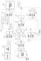
- FIG. 1 is an overall configuration diagram showing a vehicle control system 1 mounted on a vehicle 10.
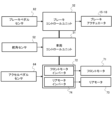
- FIG. 2 is a block diagram that shows a schematic diagram of each of the braking and driving control systems in the vehicle control system 1.
- the vehicle 10 has a pair of left and right front wheels 11, 12 and a pair of left and right rear wheels 13, 14.
- the vehicle 10 also includes, as driving force actuators that apply driving force to the vehicle 10, a front motor 71 that applies driving force to the front wheels 11, 12 and a rear motor 73 that applies driving force to the rear wheels 13, 14.
- the front motor inverter 72 controls the drive of the front motor 71
- the rear motor inverter 74 controls the drive of the rear motor 73 .
- the front motor inverter 72 and the rear motor inverter 74 each have an inverter circuit and an ECU (Electronic Control Unit) that outputs a signal to control the inverter circuit.
- the ECU of the front motor inverter 72 and the ECU of the rear motor inverter 74 acquire information on the amount of operation of the accelerator pedal 63 from the accelerator pedal sensor 64, and output a control signal corresponding to a target driving force based on the amount of operation of the accelerator pedal 63 to the inverter circuit, thereby causing the front motor 71 and the rear motor 73 to generate driving force corresponding to the amount of operation of the accelerator pedal 63.
- the vehicle 10 also includes a steering device that changes the steering angle of the front wheels 11 , 12 , which are steered wheels, in response to the steering operation of the steering wheel 51 .
- the steering wheel 51 is equipped with a steering angle sensor 52 that detects the rotation angle of the steering wheel 51 as a steering angle.
- the vehicle 10 also includes a braking system.
- the braking system includes a brake control unit 32, a brake pedal sensor 62 that detects the amount of operation of a brake pedal 61, and brake actuators 15, 16, 17, and 18 provided on each of the wheels 11, 12, 13, and 14.
- the brake control unit 32 controls the friction braking forces applied by the brake actuators 15 , 16 , 17 , and 18 to the respective wheels 11 , 12 , 13 , and 14 based on the output of the brake pedal sensor 62 .
- the front motor 71 and the rear motor 73 are used as power sources and selectively perform regenerative operations, with the front motor 71 constituting a front braking/driving device that applies braking/driving forces to the front wheels 11, 12, and the rear motor 73 constituting a rear braking/driving device that applies braking/driving forces to the rear wheels 13, 14.
- the vehicle control unit 31 obtains a signal related to the steering angle from the steering angle sensor 52 . Then, the vehicle control unit 31 outputs control commands relating to braking and driving to the brake control unit 32 , the ECU of the front motor inverter 72 , and the ECU of the rear motor inverter 74 .
- the microcomputers provided in the ECU of the front motor inverter 72, the ECU of the rear motor inverter 74, the brake control unit 32, and the vehicle control unit 31 include an MPU (Microprocessor Unit), a ROM (Read Only Memory), a RAM (Random Access Memory), etc., and realize various functions by running programs stored in the ROM as a storage unit using the MPU.
- MPU Microprocessor Unit
- ROM Read Only Memory
- RAM Random Access Memory
- the vehicle control unit 31 calculates a first braking force to be generated by the front braking/driving device and a first driving force to be generated by the rear braking/driving device based on the speed of the vehicle 10 and physical quantities related to the steering angle of the vehicle 10, and outputs a first control command to generate the first braking force and the first driving force.
- This turning control increases the lateral acceleration of the vehicle 10, which in turn increases the amount of lateral movement, thereby improving the turning performance of the vehicle 10.
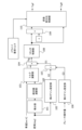
- FIG. 3 is a block diagram showing functional parts of the vehicle control unit 31 for the turning control of the first embodiment.
- the differentiating section 101 receives a signal of the steering angle ⁇ [deg] from the steering angle sensor 52, and differentiates the steering angle ⁇ with respect to time to obtain a steering angle velocity ⁇ [deg/s].
- the steering angle ⁇ is zero when in the neutral position (in other words, the straight-ahead position), and the directions to the left and right from the neutral position are represented by positive and negative signs.
- the absolute value calculation unit 102 obtains the signal of the steering angular velocity ⁇ from the differentiation unit 101, and calculates the absolute value
- the torque calculation unit 103 acquires a signal of the absolute value
- the torque calculation unit 103 refers to a torque map in which the braking/driving torque T is set for each combination of the absolute value
- the torque map is stored in a non-volatile memory such as a ROM of a microcomputer provided in the vehicle control unit 31.
- a non-volatile memory such as a ROM of a microcomputer provided in the vehicle control unit 31.
- the configuration is not limited to determining the braking/driving torque T using a torque map, and the torque calculation unit 103 can determine the braking/driving torque T by a calculation process using the absolute value
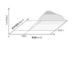
- FIG. 4 is a diagram showing an outline of a torque map.
- the braking/driving torque T is set to zero.
- the first threshold value THV1 which is the first speed threshold value
- the first threshold value TH ⁇ 1 which is the first angular velocity threshold value
- the first threshold value TH ⁇ 1 is set to, for example, about 50 deg/s.
- the region in which the braking/driving torque T is set to zero is a region in which the braking/driving torque command for the turning control ultimately becomes zero, and thus the turning control is not intervened, in other words, the turning control is essentially canceled.
- the torque map in a region where the vehicle speed V exceeds the first threshold value THV1 and the absolute value
- FIG. 5 is a diagram showing the tendency of the correlation between the vehicle speed V and the braking/driving torque T in the torque map shown in FIG.
- the braking/driving torque T is set to zero, and no turning control is performed. Furthermore, the braking/driving torque T becomes a maximum value (maximum value) in a region where the vehicle speed V exceeds the first threshold value THV1.
- the braking/driving torque T increases as the vehicle speed V increases when the vehicle speed V is between the first threshold value THV1 and the second threshold value THV2, and decreases as the vehicle speed V increases in the region where the vehicle speed V exceeds the second threshold value THV2.
- FIG. 6 is a diagram showing the tendency of the correlation between the absolute value
- the braking/driving torque T is set to zero, and no turning control is intervened.
- the braking/driving torque T becomes a maximum value in a region where the absolute value
- the braking/driving torque T increases in accordance with an increase in the absolute value
- the torque map is set so that the turning control does not intervene.
- the torque map is set so that turning control intervenes.
- the torque calculation unit 103 outputs a signal of the braking/driving torque T calculated based on the absolute value
- a first multiplier 104 multiplies the braking/driving torque T by a first gain G1 and outputs the result as a signal of the required braking/driving torque Ttg.
- the second gain setting unit 105 acquires a signal of the steering angle ⁇ , and outputs a signal of a second gain G2 based on the steering angle ⁇ .
- FIG. 7 illustrates the correlation between the absolute value of the steering angle ⁇ and the second gain G2 (1.0 ⁇ G2 ⁇ 0).
- the second gain setting unit 105 sets the second gain G2 to zero when the steering angle ⁇ is zero and in the neutral position (neutral angle), and sets the second gain G2 to a larger value as the absolute value of the steering angle ⁇ becomes larger within the range of 1.0 ⁇ G2 ⁇ 0.
- the second gain G2 based on the steering angle ⁇ is set to zero or near zero, so that the required braking/driving torque Ttg output by the first multiplication unit 104 is set to zero or near zero, and the required braking/driving torque Ttg increases as the steering angle ⁇ moves away from the neutral position.
- the third gain setting unit 106 obtains a signal of the brake operation amount (in other words, the operation amount of the brake pedal 61) from the brake pedal sensor 62, and outputs a signal of a third gain G3 based on the brake operation amount.
- FIG. 8 illustrates an example of the correlation between the brake operation amount and the third gain G3 (1.0 ⁇ G3 ⁇ 0).
- the third gain setting unit 106 sets the third gain G3 to 1.0, and as the brake operation amount increases (in other words, as the demand for frictional braking force increases), it brings the third gain G3 closer to zero.
- the greater the amount of brake operation by the driver the smaller the required braking/driving torque Ttg output by the first multiplication unit 104 is changed to, thereby preventing the application of braking/driving force by turning control from interfering with the realization of a rapid deceleration request.
- the limiter control unit 108 acquires the signal of the required braking/driving torque Ttg output by the first multiplication unit 104, and limits the required braking/driving torque Ttg to a torque range that can be output by the braking/driving force system of the vehicle control system 1, and outputs the torque. In other words, when the required braking/driving torque Ttg output by the first multiplication unit 104 exceeds the upper limit value Ttgmax, the limiter control unit 108 outputs the upper limit value Ttgmax as the required braking/driving torque Ttg.
- the limiter control section 108 outputs the required braking/driving torque Ttg output by the first multiplication section 104 as is as the required braking/driving torque Ttg.
- the limiter control unit 108 outputs a signal of the required braking/driving torque Ttg limited to below the upper limit value Ttgmax to the third multiplication unit 109 as the required braking/driving torque TtgF for the front wheels 11, 12, and outputs it to the front/rear distribution ratio control unit 110 as the required braking/driving torque TtgR for the rear wheels 13, 14.
- a third multiplication unit 109 multiplies the signal of the required braking/driving torque Ttg obtained from the limiter control unit 108 by ⁇ 1, which is a fixed value, and inverts the sign of the required braking/driving torque Ttg from plus to minus.
- a positive required braking/driving torque Ttg represents a request for driving torque
- a negative required braking/driving torque Ttg represents a request for braking torque. Therefore, the process in which the third multiplication unit 109 multiplies the signal of the required braking/driving torque Ttg by ⁇ 1 is equivalent to setting the required braking/driving torque TtgF of the front wheels 11, 12 as the braking request.
- the required braking/driving torque TtgR of the rear wheels 13, 14 is given to the front/rear distribution ratio control unit 110 with the sign of the output of the limiter control unit 108 unchanged, so that the required braking/driving torque Ttg is a positive value, that is, a driving torque is requested.
- the front/rear distribution ratio control unit 110 acquires signals of the negative required braking/driving torque TtgF, the positive required braking/driving torque TtgR, and the driver's required torque, and distributes the braking/driving torque between the front and rear wheels according to the driver's required torque, as described below.
- the front/rear distribution ratio control unit 110 then outputs a braking torque command based on the required braking/driving torque TtgF after distribution control to the front motor 71, causing the front motor 71 to generate regenerative torque (in other words, braking torque).
- the front/rear distribution ratio control unit 110 outputs a drive torque command based on the required braking/driving torque TtgR after distribution control to the rear motor 73, causing the rear motor 73 to generate motor torque (in other words, drive torque).
- the front/rear distribution ratio control unit 110 basically sets the front/rear distribution ratio to 50:50, which makes the magnitude of the braking/driving force applied to the front wheels 11, 12 the same as the magnitude of the braking/driving force applied to the rear wheels 13, 14, so that no acceleration or deceleration of the vehicle 10 occurs, and ensures that the braking/driving forces applied by the cornering control are offset by the front and rear wheels.
- a braking torque equivalent to the required braking/driving torque Ttg output by the limiter control section 108 is applied to the front wheels 11 , 12
- a driving torque equivalent to the required braking/driving torque Ttg output by the limiter control section 108 is applied to the rear wheels 13 , 14 . This prevents the driver from accelerating or decelerating unintended by the implementation of turning control.
- the front/rear distribution ratio control unit 110 sets the front/rear distribution ratio from the basic value of 50:50 to a predetermined distribution ratio other than 50:50 depending on the acceleration/deceleration state of the vehicle 10 and other factors.
- the front/rear distribution ratio control unit 110 sets the distribution ratio between the magnitude of the braking force applied to the front wheels 11, 12 and the magnitude of the driving force applied to the rear wheels 13, 14 when the vehicle 10 accelerates to, for example, 40:60.
- the front/rear distribution ratio control unit 110 makes the magnitude of the braking force applied to the front wheels 11, 12 smaller than when the front/rear distribution ratio is the basic value of 50:50, while relatively making the magnitude of the driving force applied to the rear wheels 13, 14 larger than when the front/rear distribution ratio is the basic value of 50:50.
- the front/rear distribution ratio control unit 110 sets a distribution ratio that relatively reduces the braking force applied to the front wheels 11, 12 in turning control, for example, when the vehicle 10 accelerates and the driving torque generated by the rear motor 73 is likely to exceed a limit due to the intervention of turning control.
- the driving force applied to the rear wheels 13, 14 is reduced in order to offset the braking force applied to the front wheels 11, 12, and the driving force that can be generated by the rear motor 73 for acceleration can be increased accordingly, making it possible to satisfy the driver's acceleration request with motor torque within the limit.
- the front/rear distribution ratio control unit 110 sets the distribution ratio between the magnitude of the braking force applied to the front wheels 11, 12 and the magnitude of the driving force applied to the rear wheels 13, 14 when the vehicle 10 decelerates to, for example, 60:40.
- the front/rear distribution ratio control unit 110 makes the magnitude of the braking force applied to the front wheels 11, 12 greater than when the front/rear distribution ratio is the basic value of 50:50, while relatively making the magnitude of the driving force applied to the rear wheels 13, 14 smaller than when the front/rear distribution ratio is the basic value of 50:50.
- the front/rear distribution ratio control unit 110 sets a distribution ratio that relatively reduces the driving force applied to the rear wheels 13, 14 in the turning control, for example, when the vehicle 10 decelerates and the regenerative torque generated by the front motor 71 is likely to exceed a limit due to the intervention of the turning control.
- the braking force applied to the front wheels 11, 12 is reduced to offset the driving force applied to the rear wheels 13, 14, and the braking force (in other words, regenerative torque) that can be generated by the front motor 71 for deceleration can be increased accordingly, making it possible to satisfy the driver's deceleration request with regenerative torque within limits.
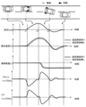
- FIG. 9 illustrates an example of a change in the vehicle state when cornering control is performed in which a braking force is applied to the front wheels 11, 12 and a driving force is applied to the rear wheels 13, 14.
- FIG. 9 shows the changes in steering angle ⁇ [deg], lateral acceleration [G], lateral movement amount [m], braking/driving torque [Nm] of the front wheels 11, 12, and braking/driving torque [Nm] of the rear wheels 13, 14 when the vehicle 10 is traveling on a two-lane road and changes lanes from the left lane to the right lane.
- the vehicle control unit 31 determines the relevant steering operation (i.e., primary steering) based on the change in the steering angle ⁇ , and outputs control commands to the front braking/driving device and the rear braking/driving device to increase the required braking/driving torque Ttg, apply braking torque to the front wheels 11, 12, and apply driving torque to the rear wheels 13, 14.
- the lateral acceleration of the vehicle 10 is increased by this braking/driving control, and the amount of lateral movement of the vehicle 10 is increased, thereby improving the turning performance.
- the braking torque applied to the front wheels 11, 12 and the driving torque applied to the rear wheels 13, 14 are offset, preventing the occurrence of acceleration or deceleration unintended by the driver.
- the vehicle control unit 31 judges between primary steering, in which the steering wheel 51 is turned in either the left or right direction from the neutral position, and secondary steering, in which the steering wheel 51 is turned in the other direction after the primary steering.
- the vehicle control unit 31 applies a braking force to the front wheels 11, 12 and a driving force to the rear wheels 13, 14 during primary steering, and switches to a state in which a driving force is applied to the front wheels 11, 12 and a braking force is applied to the rear wheels 13, 14 during secondary steering.
- the vehicle control unit 31 calculates a first braking force to be generated by the front braking/driving device and a first driving force to be generated by the rear braking/driving device based on the speed of the vehicle 10 and physical quantities related to the steering angle ⁇ , and outputs a first control command to generate the first braking force and the first driving force. Furthermore, during secondary steering after primary steering, the vehicle control unit 31 calculates a second driving force to be generated by the front braking/driving device and a second braking force to be generated by the rear braking/driving device based on the speed of the vehicle 10 and a physical quantity related to the steering angle ⁇ , and outputs a second control command to generate the second driving force and the second braking force.
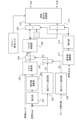
- FIG. 10 is a block diagram showing functional parts of the vehicle control unit 31 for the turning control of the second embodiment.
- the vehicle control unit 31 of the second embodiment includes an absolute value calculation section 111, a differentiation section 112, and a fourth multiplication section 113 in addition to the functional sections shown in FIG.
- the absolute value calculation unit 111 calculates the absolute value
- the differentiation unit 112 obtains the steering angular velocity ⁇
- the differentiation unit 112 outputs a signal of +1 during primary steering, in which the steering wheel 51 is turned in either the left or right direction from the neutral position, and outputs a signal of -1 during secondary steering, in which the steering wheel 51 is turned in the other direction after the primary steering. Therefore, the output signal of the differentiating section 112 is a signal indicating the result of the determination of the primary steering or the secondary steering.
- the third multiplication unit 109 multiplies the signal of the required braking/driving torque Ttg obtained from the limiter control unit 108 by a fixed value of -1, and further multiplies it by the output signal of the differentiation unit 112 (-1 or +1), and outputs it as the required braking/driving torque TtgF of the front wheels 11, 12.
- the fourth multiplier 113 multiplies the signal of the required braking/driving torque Ttg obtained from the limiter control unit 108 by the output signal ( ⁇ 1 or +1) of the differentiation unit 112 and outputs the result as the required braking/driving torque TtgR for the rear wheels 13, 14.
- the third multiplication unit 109 outputs a negative value indicating a braking request as the required braking/driving torque TtgF of the front wheels 11, 12, and the fourth multiplication unit 113 outputs a positive value indicating a driving request as the required braking/driving torque TtgR of the rear wheels 13, 14.
- the third multiplication unit 109 outputs a positive value indicating a drive request as the required braking/driving torque TtgF of the front wheels 11, 12, and the fourth multiplication unit 113 outputs a negative value indicating a braking request as the required braking/driving torque TtgR of the rear wheels 13, 14.
- the required braking/driving torques TtgF, TtgR are set to be positive or negative so as to apply a braking force to the front wheels 11, 12 and a driving force to the rear wheels 13, 14, and in the secondary steering after the primary steering, the required braking/driving torques TtgF, TtgR are set to be positive or negative so as to apply a driving force to the front wheels 11, 12 and a braking force to the rear wheels 13, 14.
- the lateral acceleration (in other words, the amount of lateral movement) increases during primary steering, improving the turning performance of the vehicle 10, and the convergence of the lateral acceleration can be accelerated during secondary steering, improving the stability performance of the vehicle 10.
- FIG. 11 illustrates an example of changes in the vehicle state in the second embodiment, in which a braking force is applied to the front wheels 11, 12 and a driving force is applied to the rear wheels 13, 14 in primary steering, and a driving force is applied to the front wheels 11, 12 and a braking force is applied to the rear wheels 13, 14 in secondary steering.
- the driver starts to turn the steering wheel 51 from the neutral position to the right from time t1 in order to change lanes (in other words, turn), and starts to turn the steering wheel 51 back to the neutral position from time t2.
- a braking force is applied to the front wheels 11, 12 and a driving force is applied to the rear wheels 13, 14, thereby increasing the lateral acceleration (lateral movement amount) of the vehicle 10 and improving the turning performance of the vehicle 10.
- a driving force is applied to the front wheels 11, 12 and a braking force is applied to the rear wheels 13, 14, thereby accelerating the convergence of the lateral acceleration of the vehicle 10 and improving the stability performance of the vehicle 10.
- FIG. 12 is a block diagram showing functional parts of the vehicle control unit 31 for the turning control of the third embodiment.
- the same blocks as those in FIG. 3 and FIG. 10 are denoted by the same reference numerals, and detailed description thereof will be omitted.
- the vehicle control unit 31 of the third embodiment has a primary steering/secondary steering determination section 120 instead of the absolute value calculation section 111 and the differentiation section 112 shown in FIG. Furthermore, in the vehicle control unit 31 of the third embodiment, the front/rear distribution ratio control unit 110 is equipped with a front/rear distribution ratio control unit 110A having the same function as the front/rear distribution ratio control unit 110 of the first embodiment, and a rate limit determination unit 140.
- the third multiplication unit 109 and the fourth multiplication unit 113 are configured to switch between driving demand and braking demand by switching between positive and negative of the required braking/driving torques TtgF, TtgR based on the primary steering and secondary steering judgment signals output by the primary steering/secondary steering judgment unit 120.
- the primary steering/secondary steering determination unit 120 basically determines whether the primary steering or secondary steering is to be performed based on whether the differential value ⁇
- the primary steering/secondary steering judgment unit 120 is configured to continue judging secondary steering in the return-to-steer state even if the differential value ⁇
- FIG. 13 is a block diagram showing the primary steering/secondary steering determination unit 120 and the rate limit determination unit 140 in detail.
- the absolute value calculation unit 121 calculates the absolute value
- the first switch unit 122 compares the absolute value
- the first switch unit 122 outputs 1 when the absolute value
- the delay section 123 holds the previous value of the output of the first switch section 122 .
- the first comparison operation unit 124 compares the output of the delay unit 123 (that is, the previous value of the output of the first switch unit 122) with 0, and outputs 1 when the output of the delay unit 123 is 0.
- the second comparison operation section 125 compares the output of the first switch section 122 (that is, the current value) with 1, and outputs 1 when the output of the first switch section 122 is 1.
- the logical product operation section 126 operates the logical product of the output of the first comparison operation section 124 and the output of the second comparison operation section 125 .
- the output of the first switch unit 122 switches from 0 to 1, and at this time, the output of the first comparison calculation unit 124 and the output of the second comparison calculation unit 125 both become 1, and the logical product calculation unit 126 outputs 1.
- the second switch section 127 outputs 1 when the output of the logical product operation section 126 is 1 or greater (i.e., the output of the logical product operation section 126 is 1), and outputs the output of the third switch section 128, which will be described later, when the output of the logical product operation section 126 is less than 1 (i.e., the output of the logical product operation section 126 is 0).
- the third switch unit 128 outputs 0 when the timer x output by the adder unit 130 described later becomes equal to or greater than the second threshold value x2, and outputs the previous value of the output of the second switch unit 127 held by the delay unit 129 if the timer x is less than the second threshold value x2.
- the initial value of the delay unit 129 is zero.
- the output of the AND operation section 126 is 0, the output of the third switch section 128 is also 0, and the output of the second switch section 127 is maintained at 0. Then, when the output of the logical product operation unit 126 switches to 1, the output of the second switch unit 127 switches to 1, and even if the output of the logical product operation unit 126 returns to 0 next time, the output of the delay unit 129 will maintain the previous value of 1, so that the output of the second switch unit 127 will continue to maintain 1.
- the second switch section 127 switches from a state of outputting 0 to a state of outputting 1.
- the output of the second switch section 127 is then provided to the adder section 130 as the addition amount.
- the adder 130 adds the output of the second switch section 127 to the output of the fourth switch section 131 and outputs the result as timer x.
- the fourth switch section 131 resets its output to 0 when the output of the third switch section 128 is 0, but outputs the previous value of the output of the addition section 130 held by the delay section 132 (in other words, the previous value of timer x) while the output of the third switch section 128 is 1.
- the timer x which is the output of the adder unit 130, is incremented by one.
- the timer x becomes equal to or greater than the second threshold value x2
- the output of the third switch section 128 becomes 0, and the output of the fourth switch section 131 also becomes 0, and the timer x is reset to 0.
- the differentiating section 133 obtains the absolute value
- the positive/negative judgment unit 134 judges that this is a primary steering state in which a braking force is applied to the front wheels 11, 12 and a driving force is applied to the rear wheels 13, 14, and outputs a signal of +1.
- the positive/negative judgment unit 134 judges that this is a secondary steering state in which a driving force is applied to the front wheels 11, 12 and a braking force is applied to the rear wheels 13, 14, and outputs a signal of -1.
- the fifth switch unit 135 is a functional unit that switches the output (i.e., the decision signal for primary steering or secondary steering) by comparing the timer x with thresholds x1, x2 (x2>X1 ⁇ 0).
- the fifth switch unit 135 outputs the output of the positive/negative judgment unit 134 (i.e., the judgment signal for primary steering or secondary steering) as is when the timer x is equal to or less than the first threshold value x1 (x ⁇ x1) or when the timer x is equal to or greater than the second threshold value x2 (x ⁇ x2).
- the fifth switch section 135 sets the previous value of the output of the fifth switch section 135 held by the delay section 136 as the current output value.
- the steering wheel 51 when the steering wheel 51 is turned to the left or right from the neutral position, such as when starting to change lanes, the steering angular velocity ⁇
- the positive/negative determination unit 134 determines the primary steering that applies a braking force to the front wheels 11 and 12 and a driving force to the rear wheels 13 and 14 .
- the timer x starts counting up when the steering wheel 51 returns to near the neutral position (more specifically, when it reaches a predetermined steering angle immediately before the neutral position).
- is negative, so the positive/negative determination unit 134 is in a state in which it determines that a secondary steering has been performed.
- the fifth switch section 135 continues to output the secondary steering judgment at the time when the timer x starts to count up.
- the output of the positive/negative judgment unit 134 switches from a secondary steering judgment to a primary steering judgment, and the control switches from applying driving force to the front wheels 11, 12 to improve stability to control applying braking force to the front wheels 11, 12 to improve turning ability.
- the stability of the vehicle 10 is improved when the lane change (in other words, turning) is completed by continuing the judgment of secondary steering when the steering wheel 51 is turned back to near the neutral position and then turned in the opposite direction from the neutral position.
- the vehicle control unit 31 includes a rate limit determination section 140 as a functional section for ensuring the braking/driving forces to be applied to the front and rear wheels when the secondary steering determination is continued.
- the rate limit determination unit 140 includes a rate limit processing unit 141 , a select-high processing unit 142 , and a sixth switch unit 143 .
- the rate limit processing unit 141 obtains a signal of the required braking/driving torque TtgF of the front wheels 11, 12 from the third multiplication unit 109, performs rate limit processing to limit the change in the required braking/driving torque TtgF, and outputs the signal after the rate limit processing (i.e., the braking/driving force limit value) as the required braking/driving torque TtgFRL. For example, when the required braking/driving torque TtgF decreases, the rate limit processing unit 141 outputs the required braking/driving torque TtgFRL which decreases more slowly than the required braking/driving torque TtgF.
- the select-high processing unit 142 outputs the larger of the required braking/driving torque TtgFRL after rate limit processing output by the rate limit processing unit 141 and the required braking/driving torque TtgF output by the third multiplication unit 109 as the required braking/driving torque TtgF. Therefore, when the required braking/driving torque TtgF decreases, the select-high processing unit 142 selects the required braking/driving torque TtgFRL that is greater than the required braking/driving torque TtgF output by the third multiplication unit 109 .
- the sixth switch unit 143 outputs either the output of the select-high processing unit 142 or the output of the third multiplication unit 109 as the required braking/driving torque TtgF of the front wheels 11, 12 based on the primary steering and secondary steering judgment signal output by the primary steering/secondary steering judgment unit 120 (fifth switch unit 135).
- the sixth switch unit 143 selects and outputs the output of the select high processing unit 142.
- the sixth switch unit 143 outputs the output of the third multiplication unit 109 as the required braking/driving torque TtgF as is.
- the required braking/driving torque TtgR of the rear wheels 13, 14 is set as a signal having the same absolute value as the required braking/driving torque TtgF output from the sixth switch section 143 but with an inverted sign.
- the required braking/driving torques TtgF, TtgR set by the processing in the rate limit determination section 140 are subjected to the front/rear distribution ratio control section 110A, and finally, the braking/driving torques to be applied to the front and rear wheels are determined.
- the primary steering/secondary steering determination unit 120 continues to determine the secondary steering when the steering wheel 51 is turned back to near the neutral position and then turned in the opposite direction from the neutral position. However, the required braking/driving torque TtgF before processing by the rate limit determination section 140 at this time decreases to zero once when the steering angle ⁇ crosses the neutral position, and then increases.
- the effect of improving the stability of the vehicle 10 i.e., the effect of accelerating the convergence of lateral acceleration
- the output of the select-high processing unit 142 gradually decreases before and after the steering angle ⁇ crosses the neutral position, if braking and driving forces are applied to the front and rear wheels based on the output of the select-high processing unit 142 when secondary steering is determined, the effect of improving the stability of the vehicle 10 (the effect of accelerating the convergence of lateral acceleration) can be stably obtained.
- Figure 14 shows the changes in steering angle ⁇ , lateral acceleration, lateral movement amount, braking/driving torque of the front wheels 11, 12, and braking/driving torque of the rear wheels 13, 14 when turning control is performed when the vehicle 10 changes lanes using the block diagram configurations of Figures 12 and 13.
- the steering wheel 51 is turned from the neutral position to start changing lanes.
- the vehicle control unit 31 applies a braking torque to the front wheels 11, 12 and applies a driving force to the rear wheels 13, 14.
- the lateral acceleration increases and the turning ability is improved.
- the vehicle control unit 31 applies a driving torque to the front wheels 11, 12 and a braking torque to the rear wheels 13, 14 based on the determination of the secondary steering.
- the steering angle ⁇ returns to the neutral position, but thereafter, the steering angle ⁇ passes through the neutral position and changes to the opposite side.
- the steering angle ⁇ changes in a direction away from the neutral position, but the vehicle control unit 31 continues to apply drive torque to the front wheels 11, 12 and braking torque to the rear wheels 13, 14 (i.e., continues to determine secondary steering).
- the function of the rate limit judgment unit 140 described above prevents the braking/driving forces applied to the front and rear wheels from decreasing, so that the effect of improving stability performance by continuing the secondary steering judgment can be maximized.
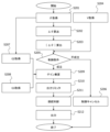
- the flowchart in FIG. 15 shows a process of turning control that applies braking/driving torque to the front and rear wheels based on the determination of primary steering/secondary steering, which is common to the second and third embodiments.
- the vehicle control unit 31 acquires information on the steering angle ⁇ in step S201, differentiates the steering angle ⁇ to obtain a steering angular velocity ⁇ in step S202, and obtains the absolute value
- the vehicle control unit 31 acquires information on the vehicle speed V in step S204. Then, in step S205, the vehicle control unit 31 determines whether the absolute value
- step S206 If the absolute value
- step S209 the vehicle control unit 31 multiplies the torque T corresponding to the absolute value
- of the current steering angular velocity ⁇ and the vehicle speed V by the gains G2 and G3 to obtain a required braking/driving torque Ttg (Ttg T ⁇ G2 ⁇ G3).
- step S207 the vehicle control unit 31 sets a second gain G2 based on the steering angle ⁇ , and in step S208, sets a third gain G3 based on the brake operation amount. Then, in step S209, the vehicle control unit 31 uses these gains G2 and G3 to determine the required braking/driving torque Ttg.
- step S210 the vehicle control unit 31 limits the required braking/driving torque Ttg so that it does not exceed the upper limit value in the vehicle control system 1.
- step S211 the vehicle control unit 31 determines whether to perform primary steering or secondary steering, in other words, whether to apply a braking force to the front wheels 11, 12 and a driving force to the rear wheels 13, 14, or whether to apply a driving force to the front wheels 11, 12 and a braking force to the rear wheels 13, 14, based on the absolute value
- step S212 the vehicle control unit 31 outputs control commands to apply braking/driving forces to the front and rear wheels based on the determination of primary steering or secondary steering and the calculation result of the required braking/driving torque Ttg.
- the vehicle control unit 31 sets the application of a braking force to the front wheels 11, 12 and a driving force to the rear wheels 13, 14 based on the required braking/driving torque Ttg.
- the vehicle control unit 31 sets the driving force to be applied to the front wheels 11, 12 and the braking force to the rear wheels 13, 14 based on the required braking/driving torque Ttg.
- the vehicle control unit 31 when the vehicle is steered in the opposite direction beyond the neutral position after steering back, the vehicle control unit 31 continues to judge secondary steering and continues control to apply driving force to the front wheels 11, 12 and braking force to the rear wheels 13, 14 around the neutral position.
- the first threshold value THV1 which is the condition for the vehicle speed V at which turning control is initiated
- the first threshold value TH ⁇ 1 which is the condition for the absolute value
- the vehicle control unit 31 executes a control step of applying a braking force to the front wheels 11, 12 and applying a driving force to the rear wheels 13, 14.
- the vehicle control unit 31 executes a control step of increasing the braking force applied to the front wheels 11, 12 and the driving force applied to the rear wheels 13, 14 compared to when the steering wheel is turned at 60 deg/s.
- the braking force applied to the front wheels 11, 12 and the driving force applied to the rear wheels 13, 14 are greater when the steering wheel 51 is turned at 70 deg/s than when it is turned at 60 deg/s, which means that, at least between 60 deg/s and 70 deg/s, a control step is executed that increases the braking and driving forces applied to the front and rear wheels as the steering angular speed increases.
- the vehicle control unit 31 executes a control step of applying driving force to the front wheels 11, 12 and applying braking force to the rear wheels 13, 14.
- a driving force is applied to the front wheels 11, 12 and a braking force is applied to the rear wheels 13, 14, which corresponds to the implementation of the present invention.
- At least one of the driving force actuator that applies driving force to the front wheels 11, 12 and the driving force actuator that applies driving force to the rear wheels 13, 14 may be an internal combustion engine.
- the braking force applied to the wheels for turning control can be friction braking force by the brake actuators 15, 16, 17, and 18 instead of regenerative braking force by the motor.
- regenerative braking is used in turning control, it is possible to improve responsiveness and control performance compared to when friction braking is used.
- the vehicle control unit 31 determines the period for which the secondary steering judgment is to be continued based on the time from when the steering angle ⁇ is turned back to near the neutral position, but the continuation judgment can be canceled based on the steering angle ⁇ , the steering angle speed ⁇ , etc. before the set time is reached. For example, while continuing to make a secondary steering judgment, the vehicle control unit 31 can switch the secondary steering judgment to a primary steering judgment when the absolute value of the steering angle ⁇ exceeds a set value or when the steering angle speed in the direction away from the neutral position exceeds a set value.
- the vehicle control unit 31 when setting the third gain G3 based on the brake operation amount, can set the third gain G3 to 1.0 when the brake operation amount is equal to or less than a set value, and can set the third gain G3 to zero when the brake operation amount exceeds the set value. That is, the vehicle control unit 31 can switch the turning control on and off (in other words, whether or not to intervene in the turning control) by comparing the brake operation amount with a set value.
- the vehicle control unit 31 can implement the turning control of the first embodiment when the vehicle 10 is in emergency avoidance mode, such as when the vehicle 10 is avoiding an obstacle, and can implement turning control that reverses braking/driving based on the judgment of primary steering and secondary steering of the second or third embodiment when the vehicle is not in emergency avoidance mode. This is because in the emergency avoidance mode, turning performance is more important than stability performance.
- the vehicle control unit 31 corresponds to the vehicle control device that executes turning control, but a control unit that controls braking, such as the brake control unit 32, or a control unit that controls driving, such as the motor inverters 72, 74, can be the entity that executes turning control.
- the computational processing for turning control can be shared among multiple control units.
Landscapes
- Engineering & Computer Science (AREA)
- Automation & Control Theory (AREA)
- Transportation (AREA)
- Mechanical Engineering (AREA)
- Steering Control In Accordance With Driving Conditions (AREA)
- Electric Propulsion And Braking For Vehicles (AREA)
Abstract
Description
図1は、車両10に搭載される車両制御システム1を示す全体構成図である。
図2は、車両制御システム1のうち、制動、駆動の各制御系を概略的に示すブロック図である。
車両10は、左右一対の前輪11,12と、左右一対の後輪13,14とを備える。
そして、フロントモータインバータ72はフロントモータ71を駆動制御し、リアモータインバータ74はリアモータ73を駆動制御する。
フロントモータインバータ72のECU及びリアモータインバータ74のECUは、アクセルペダル63の操作量の情報をアクセルペダルセンサ64から取得し、アクセルペダル63の操作量に基づく目標駆動力に応じた制御信号をインバータ回路に出力することで、アクセルペダル63の操作量に応じた駆動力を、フロントモータ71、リアモータ73で発生させる。
ステアリングホイール51は、ステアリングホイール51の回転角を舵角として検出する舵角センサ52を備える。
制動装置は、ブレーキコントロールユニット32、ブレーキペダル61の操作量を検出するブレーキペダルセンサ62、各車輪11,12,13,14に設けられたブレーキアクチュエータ15,16,17,18を有する。
なお、フロントモータ71及びリアモータ73は、動力源として用いられるとともに、選択的に回生動作を行い、フロントモータ71は、前輪11,12に制駆動力を与えるフロント制駆動装置を構成し、リアモータ73は、後輪13,14に制駆動力を与えるリア制駆動装置を構成する。
そして、車両コントロールユニット31は、制駆動に関する制御指令を、ブレーキコントロールユニット32、フロントモータインバータ72のECU及びリアモータインバータ74のECUに出力する。
フロントモータインバータ72のECU、リアモータインバータ74のECU、ブレーキコントロールユニット32、及び、車両コントロールユニット31が備えるマイクロコンピュータは、MPU(Microprocessor Unit)、ROM(Read Only Memory)、RAM(Random Access Memory)などを備え、記憶部としてのROMに記憶されているプログラムをMPUで動作させることにより各種の機能を実現する。
車両コントロールユニット31は、旋回制御において、ステアリングホイール51が中立位置より左右いずれか一方の方向に切られる状態である1次操舵のとき、車両10の速度と、車両10の舵角に関する物理量と、に基づいてフロント制駆動装置で発生させる第1の制動力及びリア制駆動装置で発生させる第1の駆動力を求め、前記第1の制動力及び前記第1の駆動力を発生させる第1の制御指令を出力する。
係る旋回制御によって、車両10の横加速度が増加し、引いては、横移動量が増えることで、車両10の回頭性能が向上する。
以下では、旋回制御の第1実施形態を説明する。
図3は、第1実施形態の旋回制御のために車両コントロールユニット31が備える機能部を示すブロック線図である。
なお、舵角θは、中立位置(換言すれば、直進位置)であるときにゼロであり、中立位置から左右の方向がプラス、マイナスの符号で表される。
絶対値演算部102は、微分部101から舵角速度Δθの信号を取得し、舵角速度Δθの絶対値|Δθ|を求める。
ここで、トルク演算部103は、舵角速度Δθの絶対値|Δθ|と車速Vとの組み合わせ毎に制駆動トルクTが設定されたトルクマップを参照し、そのときの舵角速度Δθの絶対値|Δθ|及び車速Vの組み合わせに該当する制駆動トルクTを検索する。
但し、トルクマップを用いて制駆動トルクTを求める構成に限定されず、トルク演算部103は、舵角速度Δθの絶対値|Δθ|と車速Vとを変数とする演算処理で、制駆動トルクTを求めることができる。
トルクマップにおいて、車速Vが第1閾値THV1(THV1>0)以下の領域、及び、舵角速度Δθの絶対値|Δθ|が第1閾値THθ1(THθ1>0)以下の領域では、制駆動トルクTがゼロに設定される。
なお、第1速度閾値である第1閾値THV1は、たとえば、40km/h程度の速度に設定され、第1角速度閾値である第1閾値THθ1は、たとえば、50deg/s程度に設定される。
一方、トルクマップにおいて、車速Vが第1閾値THV1を超え、かつ、舵角速度Δθの絶対値|Δθ|が第1閾値THθ1を超える領域では、制駆動トルクTがゼロよりも高い値に設定される。
前述したように、車速Vが第1閾値THV1以下のとき、制駆動トルクTはゼロに設定され、旋回制御は介入されないことになる。
また、制駆動トルクTは、車速Vが第1閾値THV1を超える領域において、極大値(最大値)となる。
つまり、制駆動トルクTが極大値となる車速Vを、第2速度閾値である第2閾値THV2とすると、制駆動トルクTは、車速Vが第1閾値THV1と第2閾値THV2との間のときは車速Vの増大に応じて増大し、車速Vが第2閾値THV2を超える領域では、車速Vの増大に応じて減少する。
前述したように、舵角速度Δθの絶対値|Δθ|が第1閾値THθ1以下のとき、制駆動トルクTはゼロに設定され、旋回制御は介入されないことになる。
また、制駆動トルクTは、舵角速度Δθの絶対値|Δθ|が第1閾値THθ1を超える領域において、極大値(最大値)となる。
つまり、制駆動トルクTが極大値となる絶対値|Δθ|を第2閾値THθ2(第2角速度閾値)とすると、制駆動トルクTは、舵角速度Δθの絶対値|Δθ|が第1閾値THθ1と第2閾値THθ2との間のときは舵角速度Δθの絶対値|Δθ|の増大に応じて増大し、舵角速度Δθの絶対値|Δθ|が第2閾値THθ2を超える領域では、舵角速度Δθの絶対値|Δθ|の増大に応じて減少する。
一方、車速Vが第1閾値THV1を超え、かつ、舵角速度Δθの絶対値|Δθ|が第1閾値THθ1を超える領域では、旋回制御が介入するようにトルクマップが設定される。
但し、車速Vや舵角速度Δθの絶対値|Δθ|が第2閾値THθ2がある値を超えるようになると、旋回制御によって車両10の走行が不安定になる可能性があるので、旋回制御で付与する制駆動力を抑えるようにトルクマップが設定される。
第1乗算部104は、制駆動トルクTに第1ゲインG1を乗算した結果を、要求制駆動トルクTtgの信号として出力する。
ここで、第1ゲインG1は、舵角θに基づく第2ゲインG2と、ブレーキ操作量に基づく第3ゲインG3とに基づき設定される(G1=G2×G3)。
図7は、舵角θの絶対値と第2ゲインG2(1.0≧G2≧0)との相関を例示する。
第2ゲイン設定部105は、舵角θがゼロで中立位置(中立角度)のときは、第2ゲインG2をゼロに設定し、1.0≧G2≧0の範囲内で、舵角θの絶対値が大きくなるほど第2ゲインG2をより大きな値に設定する。
つまり、舵角θが中立位置付近であるときは、舵角θに基づく第2ゲインG2がゼロ乃至ゼロ近傍に設定されることで、第1乗算部104が出力する要求制駆動トルクTtgはゼロ乃至ゼロ近傍に設定され、要求制駆動トルクTtgは舵角θが中立位置から離れるほど増大する。
図8は、ブレーキ操作量と第3ゲインG3(1.0≧G3≧0)との相関を例示する。
第3ゲイン設定部106は、ブレーキ操作量がゼロでブレーキ操作が行われていないときは、第3ゲインG3を1.0に設定し、ブレーキ操作量が大きくなるほど(換言すれば、摩擦制動力の要求が大きくなるほど)第3ゲインG3をゼロに近づける。
つまり、運転者によるブレーキ操作量が大きくなるほど、第1乗算部104が出力する要求制駆動トルクTtgは小さく変更され、旋回制御による制駆動力の付与が、急減速要求の実現の妨げになることを抑止する。
そして、第2乗算部107は、第2ゲインG2に第3ゲインG3を乗算した結果を第1ゲインG1(G1=G2×G3)として第1乗算部104に出力する。
第1乗算部104は、第2ゲインG2及び第3ゲインG3に基づく第1ゲインG1を、トルク演算部103が求めた制駆動トルクTに乗算した結果を、要求制駆動トルクTtg(Ttg=T×G1)の信号として出力する。
つまり、リミッタ制御部108は、第1乗算部104が出力する要求制駆動トルクTtgが上限値Ttgmaxを超えている場合、上限値Ttgmaxを要求制駆動トルクTtgとして出力する。
また、リミッタ制御部108は、第1乗算部104が出力する要求制駆動トルクTtgが上限値Ttgmax以下であれば、第1乗算部104が出力する要求制駆動トルクTtgをそのまま要求制駆動トルクTtgとして出力する。
第3乗算部109は、リミッタ制御部108から取得した要求制駆動トルクTtgの信号に、固定値である-1を乗算し、要求制駆動トルクTtgの符号をプラスからマイナスに反転させる。
したがって、第3乗算部109が、要求制駆動トルクTtgの信号に-1を乗算する処理は、前輪11,12の要求制駆動トルクTtgFを制動要求に設定する処理となる。
一方、後輪13,14の要求制駆動トルクTtgRは、リミッタ制御部108の出力の符号のまま前後配分比制御部110に与えられるから、プラスの要求制駆動トルクTtg、つまり、駆動トルクの要求となる。
そして、前後配分比制御部110は、フロントモータ71に配分制御後の要求制駆動トルクTtgFに基づく制動トルク指令を出力し、フロントモータ71で回生トルク(換言すれば、制動トルク)を発生させる。
また、前後配分比制御部110は、リアモータ73に配分制御後の要求制駆動トルクTtgRに基づく駆動トルク指令を出力し、リアモータ73でモータトルク(換言すれば、駆動トルク)を発生させる。
つまり、リミッタ制御部108が出力する要求制駆動トルクTtgに相当する制動トルクを前輪11,12に与え、リミッタ制御部108が出力する要求制駆動トルクTtgに相当する駆動トルクを後輪13,14に与える。
これにより、旋回制御の実施によって、運転者が意図しない加減速が発生することを抑止する。
前後配分比制御部110は、車両10が加速するときに、前輪11,12に付与する制動力の大きさと、後輪13,14に付与する駆動力の大きさとの配分比を、たとえば、40:60などに設定する。
つまり、前後配分比制御部110は、前輪11,12に付与する制動力の大きさを、前後配分比が基本値である50:50であるときよりも小さくする一方、相対的に、後輪13,14に付与する駆動力の大きさを、前後配分比が基本値である50:50であるときよりも大きくする。
これにより、前輪11,12に付与する制動力を相殺するために後輪13,14に与える駆動力が小さくなり、その分、リアモータ73で加速のために発生させ得る駆動力を大きくでき、リミット内のモータトルクで運転者の加速要求を満たすことが可能となる。
つまり、前後配分比制御部110は、前輪11,12に付与する制動力の大きさを、前後配分比が基本値である50:50であるときよりも大きくする一方、相対的に、後輪13,14に付与する駆動力の大きさを、前後配分比が基本値である50:50であるときよりも小さくする。
これにより、後輪13,14に付与する駆動力を相殺するために前輪11,12に与える制動力が小さくなり、その分、フロントモータ71で減速のために発生させ得る制動力(換言すれば、回生トルク)を大きくでき、リミット内の回生トルクで運転者の減速要求を満たすことが可能となる。
図9は、車両10が片側2車線の道路を走行するときに左側の車線から右側の車線に車線変更する状況での舵角θ[deg]、横加速度[G]、横移動量[m]、前輪11,12の制駆動トルク[Nm]、後輪13,14の制駆動トルク[Nm]の変化を示す。
このとき、車両コントロールユニット31は、舵角θの変化に基づき係る操舵操作(つまり、1次操舵)を判断し、要求制駆動トルクTtgを増加させ、前輪11,12に制動トルクを付与し、後輪13,14に駆動トルクを付与するように、フロント制駆動装置、リア制駆動装置に制御指令を出力する。
係る制駆動制御によって車両10の横加速度が増加することで、車両10の横移動量が増えることで、回頭性能が向上する。
また、前輪11,12に付与する制動トルクと、後輪13,14に付与する駆動トルクとが相殺され、運転者が意図しない加減速の発生が抑止される。
以下では、旋回制御の第2実施形態を説明する。
第2実施形態では、車両コントロールユニット31は、ステアリングホイール51が中立位置より左右いずれか一方の方向に切られる状態である1次操舵と、1次操舵の後に、ステアリングホイール51が他方の方向に切られる状態である2次操舵とを判断する。
そして、車両コントロールユニット31は、1次操舵では前輪11,12に制動力、後輪13,14に駆動力を付与し、2次操舵になると、前輪11,12に駆動力、後輪13,14に制動力を付与する状態に切り替える。
さらに、車両コントロールユニット31は、1次操舵の後の2次操舵のとき、車両10の速度と、舵角θに関する物理量と、に基づいてフロント制駆動装置で発生させる第2の駆動力及びリア制駆動装置で発生させる第2の制動力を求め、前記第2の駆動力及び前記第2の制動力を発生させる第2の制御指令を出力する。
なお、図10において、図3と同じブロックには同じ符号を付し、詳細な説明を省略する。
第2実施形態の車両コントロールユニット31は、図3に示した機能部に加えて、絶対値演算部111、微分部112、第4乗算部113を備える。
微分部112は、舵角θの絶対値|θ|を時間微分して舵角速度Δ|θ|を求め、舵角速度Δ|θ|の符号を示す信号、つまり、舵角θの絶対値|θ|が増大して舵角速度Δ|θ|がプラスになるときは+1の信号を出力し、舵角θの絶対値|θ|が減少して舵角速度Δ|θ|がマイナスになるときは-1の信号を出力する。
したがって、微分部112の出力信号は、1次操舵、2次操舵の判断結果を示す信号となる。
一方、第4乗算部113は、リミッタ制御部108から取得した要求制駆動トルクTtgの信号に、微分部112の出力信号(-1または+1)を乗算して、後輪13,14の要求制駆動トルクTtgRとして出力する。
一方、微分部112の出力信号が-1となる2次操舵のとき、第3乗算部109は、前輪11,12の要求制駆動トルクTtgFとして、駆動要求を示すプラスの値を出力し、第4乗算部113は、後輪13,14の要求制駆動トルクTtgRとして、制動要求を示すマイナスの値を出力する。
したがって、1次操舵においては、前輪11,12に制動力、後輪13,14に駆動力が付与され、1次操舵から2次操舵に切り替わると、前後輪の制駆動が反転され、前輪11,12に駆動力、後輪13,14に制動力が付与される。
係る第2実施形態によれば、1次操舵においては横加速度(換言すれば、横移動量)が増大して車両10の回頭性能が向上すると共に、2次操舵においては横加速度の収束を速めて車両10の安定性能を向上させることができる。
ここで、運転者が、車線変更(換言すれば、旋回)のために、時刻t1から、ステアリングホイール51を中立位置から右方向に切り始め、時刻t2からステアリングホイール51を中立位置に戻す切り戻しが開始される。
また、時刻t2から、ステアリングホイール51を中立位置に戻る時刻t3までの2次操舵のとき(換言すれば、車線変更が終了したとき、若しくは、旋回路を脱出するとき)は、前輪11,12に駆動力、後輪13,14に制動力が付与されることで、車両10の横加速度の収束が速まって車両10の安定性能が向上する。
以下では、旋回制御の第3実施形態を説明する。
第3実施形態では、切り戻しで中立位置付近に戻った後も、前輪11,12に駆動力、後輪13,14に制動力を付与する状態、つまり、2次操舵の判断を継続させることで、車両10の安定性能をより向上させる。
なお、図12において、図3、図10と同じブロックには同じ符号を付し、詳細な説明を省略する。
さらに、第3実施形態の車両コントロールユニット31は、前後配分比制御部110が、第1実施形態の前後配分比制御部110と同様な機能を有する前後配分比制御部110Aと、レートリミット判断部140とを備えている。
そして、第3乗算部109及び第4乗算部113は、1次操舵・2次操舵判断部120が出力する1次操舵、2次操舵の判断信号に基づき、要求制駆動トルクTtgF,TtgRのプラス、マイナスを切り替えることで、駆動要求と制動要求とを切り替えるよう構成される。
但し、1次操舵・2次操舵判断部120は、切り戻しで舵角θが中立位置付近に戻った後に微分値Δ|θ|のプラスに反転しても、切り戻し状態での2次操舵の判断を継続させるように構成されている。
絶対値演算部121は、舵角θの絶対値|θ|を演算する。
第1スイッチ部122は、舵角θの絶対値|θ|と、中立位置近傍の値である舵角閾値θth(θth>0)とを比較する。
そして、第1スイッチ部122は、舵角θの絶対値|θ|が舵角閾値θth以下のとき、つまり、舵角θが中立位置を含む中立位置近傍の所定範囲内であるときに1を出力し、舵角θの絶対値|θ|が舵角閾値θthを超えるとき、舵角θが中立位置近傍ではないときは0を出力する。
第1比較演算部124は、遅延部123の出力(つまり、第1スイッチ部122の出力の前回値)と0とを比較し、遅延部123の出力が0であるときに1を出力する。
また、第2比較演算部125は、第1スイッチ部122の出力(つまり、現在値)と1とを比較し、第1スイッチ部122の出力が1であるときに1を出力する。
ここで、舵角θが中立位置から離れた状態から舵角閾値θthで規定される中立位置近傍に戻ると、第1スイッチ部122の出力が0から1に切り替わることになり、このとき、第1比較演算部124の出力と、第2比較演算部125の出力とが双方ともに1になって、論理積演算部126は1を出力することになる。
第3スイッチ部128は、後述する加算部130が出力するタイマxが第2閾値x2以上になると0を出力し、タイマxが第2閾値x2未満であれば、遅延部129が保持する第2スイッチ部127の出力の前回値を出力する。
ここで、遅延部129の初期値は0である。
そして、論理積演算部126の出力が1に切り替わったとき、第2スイッチ部127の出力が1に切り替わり、次回、論理積演算部126の出力が0に戻っても、遅延部129の出力が前回値の1を保持することで、第2スイッチ部127の出力は継続して1を保持することになる。
そして、第2スイッチ部127の出力は、加算部130に加算分として与えられる。
加算部130は、第4スイッチ部131の出力に第2スイッチ部127の出力を加算して、タイマxとして出力する。
つまり、舵角θが中立位置から離れた状態から舵角閾値θthで規定される中立位置近傍に戻って、第2スイッチ部127の出力が1になると、加算部130の出力であるタイマxが1ずつ増加する。
そして、タイマxが第2閾値x2以上になると、第3スイッチ部128の出力が0になることで、第4スイッチ部131の出力も0となり、タイマxは0にリセットされる。
正負判断部134は、舵角速度Δ|θ|のプラス、マイナスの判断に基づき、前輪11,12に制動力、後輪13,14に駆動力を付与する1次操舵と、前輪11,12に駆動力、後輪13,14に制動力を付与する2次操舵とを判断する。
一方、正負判断部134は、舵角|θ|が減少変化する状態、舵角θが中立位置に近づく方向に変化する状態であって舵角速度Δ|θ|がマイナスであれば、前輪11,12に駆動力、後輪13,14に制動力を付与する2次操舵の状態であると判断し、-1の信号を出力する。
第5スイッチ部135は、タイマxが第1閾値x1以下(x≦x1)であるかまたはタイマxが第2閾値x2以上(x≧x2)であるときに、正負判断部134の出力(つまり、1次操舵、2次操舵の判断信号)をそのまま出力する。
一方、第5スイッチ部135は、タイマxが、x1<x<x2を満たす間では、遅延部136が保持する第5スイッチ部135の出力の前回値を、今回の出力値とする。
そして、ある舵角θに達した後にステアリングホイール51を中立位置に向けて戻す切り戻しが実施されると、舵角速度Δ|θ|はマイナスとなって、前輪11,12に駆動力、後輪13,14に制動力を付与する2次操舵の状態に切り替わる。
このため、正負判断部134は、前輪11,12に制動力、後輪13,14に駆動力を付与する1次操舵を判断することになる。
係るカウントアップの開始時は、舵角速度Δ|θ|がマイナスであるため、正負判断部134は2次操舵を判断する状態である。
これにより、ステアリングホイール51が中立位置付近にまで切り戻され、さらに、ステアリングホイール51が中立位置から逆方向に切られるときに、中立位置を通過することで舵角速度Δ|θ|がマイナスからプラスに反転しても(換言すれば、正負判断部134による判断が、2次操舵から1次操舵に反転しても)、第5スイッチ部135の出力は2次操舵を示す-1の信号に保持され、前輪11,12への駆動力の付与が継続される。
しかし、ステアリングホイール51が中立位置付近にまで切り戻され、さらに、中立位置から逆方向に切られるときは、車線変更などのための旋回が終了したときであるため、回頭性よりも安定性の向上を優先すべき状態である。
そこで、ステアリングホイール51が中立位置付近にまで切り戻され、さらに、中立位置から逆方向に切られるときは2次操舵の判断を継続させることで、車線変更(換言すれば、旋回)が終了するときの車両10の安定性を向上させる。
このため、舵角θが中立位置を通過するときに2次操舵の判断を継続させても、前輪11,12に付与される駆動力及び後輪13,14に付与される制動力は、中立位置付近で落ち込んでから再上昇することになり、2次操舵の判断を継続させた効果を充分に発揮させることができない。
レートリミット判断部140は、レートリミット処理部141、セレクトハイ処理部142、第6スイッチ部143を備える。
レートリミット処理部141は、たとえば要求制駆動トルクTtgFが減少するとき、要求制駆動トルクTtgFよりも減少が遅れる要求制駆動トルクTtgFRLを出力することになる。
したがって、セレクトハイ処理部142は、要求制駆動トルクTtgFが減少するときは、第3乗算部109が出力する要求制駆動トルクTtgFより大きな値となる要求制駆動トルクTtgFRLを選択する。
詳細には、第6スイッチ部143は、1次操舵・2次操舵判断部120(第5スイッチ部135)の出力が2次操舵を示す-1であるときは、セレクトハイ処理部142の出力を選択して出力する。
なお、後輪13,14の要求制駆動トルクTtgRは、第6スイッチ部143から出力される要求制駆動トルクTtgFと絶対値が同じで符号が反転された信号として設定される。
そして、上記のように、レートリミット判断部140での処理で設定された要求制駆動トルクTtgF,TtgRが、前後配分比制御部110Aの対象とされて、最終的に、前後輪に付与する制駆動トルクが決定される。
しかし、このときのレートリミット判断部140での処理前の要求制駆動トルクTtgFは、舵角θが中立位置を横切るときに一旦ゼロにまで減少してその後上昇する。
これに対し、セレクトハイ処理部142の出力は、舵角θが中立位置を横切る前後で漸減するため、2次操舵が判断されているときに、セレクトハイ処理部142の出力に基づき前後輪に制駆動力を与えれば、車両10の安定性を向上させる効果(横加速度の収束を速める効果)を安定して得ることができる。
時刻t1で、ステアリングホイール51が中立位置から切られて車線変更が開始される。
係る制駆動状態では、横加速度が増して回頭性が向上される。
このとき、車両コントロールユニット31は、2次操舵の判断に基づき、前輪11,12に駆動トルクを付与し、後輪13,14に制動トルクを付与する。
時刻t3以降は、舵角θが中立位置から離れる方向に変化するが、車両コントロールユニット31は、前輪11,12に駆動トルクを付与し、後輪13,14に制動トルクを付与する制御(つまり、2次操舵の判断)を継続する。
ここで、舵角θが中立位置を横切るときに、前述したレートリミット判断部140の機能で、前後輪に与える制駆動力が落ち込むことが抑止されるので、2次操舵の判断の継続による安定性能の向上効果を可及的に高くすることができる。
車両コントロールユニット31は、ステップS201で、舵角θの情報を取得し、ステップS202で、舵角θを微分して舵角速度Δθを求め、ステップS203で、舵角速度Δθの絶対値|Δθ|を求める。
そして、車両コントロールユニット31は、ステップS205で、舵角速度Δθの絶対値|Δθ|及び車速Vが、旋回制御の実施条件を満たしているか否か、換言すれば、現時点での舵角速度Δθの絶対値|Δθ|及び車速Vに対応する制駆動トルクTとしてゼロを設定したか否かを判断する。
一方、舵角速度Δθの絶対値|Δθ|及び車速Vが、旋回制御の実施条件を満たしている場合(換言すれば、制駆動トルクTがゼロでない場合)、車両コントロールユニット31は、ステップS209に進む。
車両コントロールユニット31は、ステップS207で、舵角θに基づき第2ゲインG2を設定し、ステップS208で、ブレーキ操作量に基づき第3ゲインG3を設定する。
そして、車両コントロールユニット31は、ステップS209で、これらのゲインG2,G3を用いて、要求制駆動トルクTtgを求める。
車両コントロールユニット31は、次のステップS211で、舵角θの絶対値|θ|、微分値Δ|θ|などに基づいて、1次操舵、2次操舵の判断、換言すれば、前輪11,12に制動力、後輪13,14に駆動力を付与するか、または、前輪11,12に駆動力、後輪13,14に制動力を付与するかを判断する。
そして、車両コントロールユニット31は、ステップS212で、1次操舵、2次操舵の判断、及び、要求制駆動トルクTtgの演算結果に基づき、前後輪に制駆動力を付与するための制御指令を出力する。
一方、車両コントロールユニット31は、1次操舵の後に、ステアリングホイール51が他方の方向に切られる状態(換言すれば、切り戻し状態)である2次操舵のとき、要求制駆動トルクTtgに基づき、前輪11,12に駆動力、後輪13,14に制動力を付与する設定を行なう。
なお、第3実施形態の車両コントロールユニット31は、切り戻しから中立位置を超えて逆側に操舵される場合、2次操舵の判断を継続し、前輪11,12に駆動力、後輪13,14に制動力を付与する制御を中立位置の前後で継続させる。
この場合、車両10が60km/hで走行中に、ステアリングホイール51が60deg/sで切られると、車両コントロールユニット31は、前輪11,12に制動力を付与し、後輪13,14に駆動力を付与する制御ステップを実行する。
つまり、車両10が60km/hで走行中に、ステアリングホイール51が60deg/sで切られたときに、前輪11,12に制動力が付与され、後輪13,14に駆動力が付与されたことは、本発明の実施に相当する。
つまり、ステアリングホイール51が60deg/sで切られるときよりも、70deg/sで切られるときに、前輪11,12に付与する制動力及び後輪13,14に付与する駆動力が大きくなることは、少なくとも60deg/sから70deg/sまでの間では、舵角速度が大きいほど前後輪に付与する制駆動力を大きくする制御ステップが実行されることを意味する。
つまり、車両10が60km/hで走行中に、ステアリングホイール51が60deg/sで時計回りに切られた後に、ステアリングホイールが60deg/sで反時計回りに切り戻されたときに、前輪11,12に駆動力が付与され、後輪13,14に制動力が付与されたことは、本発明の実施に相当する。
また、好ましい実施形態を参照して本発明の内容を具体的に説明したが、本発明の基本的技術思想及び教示に基づいて、当業者であれば、種々の変形態様を採り得ることは自明である。
また、旋回制御のために車輪に与える制動力を、モータによる回生制動力に代えて、ブレーキアクチュエータ15,16,17,18による摩擦制動力とすることができる。
但し、旋回制御において回生制動を用いる場合は、摩擦制動を用いる場合に比べて、応答性、制御性能の向上を図ることができる。
たとえば、車両コントロールユニット31は、2次操舵の判断を継続させているときに、舵角θの絶対値が設定値を超えたときや、中立位置から離れる方向への舵角速度が設定値を超えたときなどに、2次操舵の判断を1次操舵の判断に切り替えることができる。
つまり、車両コントロールユニット31は、ブレーキ操作量と設定値との比較で、旋回制御のオンオフ(換言すれば、旋回制御の介入、非介入)を切り替えることができる。
これは、緊急回避モードでは、安定性能よりも回頭性能が必要とされるためである。
また、複数のコントロールユニットで旋回制御のための演算処理を分担することができる。
Claims (15)
- 車両の前輪に制駆動力を与えるフロント制駆動装置と、前記車両の後輪に制駆動力を与えるリア制駆動装置と、を有する前記車両に備えられた車両制御装置であって、
前記車両制御装置が備えるコントロール部は、
前記車両のステアリングホイールが中立位置より左右いずれか一方の方向に切られる状態である1次操舵のとき、
前記車両の速度と、前記車両の舵角に関する物理量と、に基づいて前記フロント制駆動装置で発生させる第1の制動力及び前記リア制駆動装置で発生させる第1の駆動力を求め、
前記第1の制動力及び前記第1の駆動力を発生させる第1の制御指令を出力する、
車両制御装置。 - 請求項1に記載の車両制御装置であって、
前記コントロール部は、
前記1次操舵の後に、前記ステアリングホイールが他方の方向に切られる状態である2次操舵のとき、
前記速度と、前記舵角に関する物理量と、に基づいて前記フロント制駆動装置で発生させる第2の駆動力及び前記リア制駆動装置で発生させる第2の制動力を求め、
前記第2の駆動力及び前記第2の制動力を発生させる第2の制御指令を出力する、
車両制御装置。 - 請求項1に記載の車両制御装置であって、
前記コントロール部は、
前記速度と、前記舵角に関する物理量のうちの舵角速度と、前記舵角に関する物理量のうちの舵角と、に基づいて、前記第1の制動力及び前記第1の駆動力を求める、
車両制御装置。 - 請求項3に記載の車両制御装置であって、
前記コントロール部は、
前記速度が所定の第1速度閾値より小さく、かつ前記舵角速度が所定の第1舵角速度閾値より小さい場合は、前記第1の制動力及び前記第1の駆動力をゼロとして出力する、
車両制御装置。 - 請求項4に記載の車両制御装置であって、
前記コントロール部は、
前記速度が、前記第1速度閾値より大きく、かつ、前記第1速度閾値より大きい所定の第2速度閾値より小さい場合は、前記速度が大きい程、前記第1の制動力及び前記第1の駆動力を大きくし、
前記速度が前記第2速度閾値を超える場合は、前記速度が大きい程、前記第1の制動力及び前記第1の駆動力を小さくし、
前記舵角速度が、前記第1舵角速度閾値より大きく、かつ、前記第1舵角速度閾値より大きい所定の第2舵角速度閾値より小さい場合は、前記舵角速度が大きい程、前記第1の制動力及び前記第1の駆動力を大きくし、
前記舵角速度が前記第2舵角速度閾値を超える場合は、前記舵角速度が大きい程、前記第1の制動力及び前記第1の駆動力を小さくする、
車両制御装置。 - 請求項3に記載の車両制御装置であって、
前記コントロール部は、
前記舵角が大きい程、前記第1の制動力及び前記第1の駆動力を大きくする、
車両制御装置。 - 請求項3に記載の車両制御装置であって、
前記コントロール部は、
前記車両のブレーキ操作量に基づく摩擦制動力が大きい程、前記第1の制動力及び前記第1の駆動力を小さくする、
車両制御装置。 - 請求項3に記載の車両制御装置であって、
前記コントロール部は、
前記車両のシステムによる所定の制限をかけて、前記第1の制動力及び前記第1の駆動力を求める、
車両制御装置。 - 請求項1に記載の車両制御装置であって、
前記コントロール部は、
前記第1の制動力の大きさと前記第1の駆動力の大きさを等しくして出力する、
車両制御装置。 - 請求項1に記載の車両制御装置であって、
前記コントロール部は、
前記第1の制動力の大きさと前記第1の駆動力の大きさを所定の配分比で配分して出力する、
車両制御装置。 - 請求項2に記載の車両制御装置であって、
前記コントロール部は、
前記速度と、前記舵角に関する物理量と、に基づく制駆動力と、前記制駆動力の変化を制限した制駆動力制限値と、のセレクトハイで前記第2の駆動力及び前記第2の制動力を求める、
車両制御装置。 - 請求項1に記載の車両制御装置であって、
前記フロント制駆動装置はフロント電動モータであり、前記リア制駆動装置はリア電動モータである、
車両制御装置。 - 車両に搭載されたコントロール部が実行する車両制御方法であって、
前記車両が60km/hで走行中に、前記車両のステアリングホイールが60deg/sで切られるとき、
前記車両の前輪に制動力を付与し、前記車両の後輪に駆動力を付与する、
車両制御方法。 - 請求項13に記載の車両制御方法であって、
前記ステアリングホイールが70deg/sで切られるときは、前記ステアリングホイールが60deg/sで切られるときに対して、前記車両の前輪に付与する制動力及び前記車両の後輪に付与する駆動力を大きくする、
車両制御方法。 - 車両に搭載されたコントロール部が実行する車両制御方法であって、
前記車両が60km/hで走行中に、前記車両のステアリングホイールが60deg/sで時計回りに切られた後に、前記ステアリングホイールが60deg/sで反時計回りに切り戻されるとき、
前記車両の前輪に駆動力を付与し、前記車両の後輪に制動力を付与する、
車両制御方法。
Priority Applications (3)
| Application Number | Priority Date | Filing Date | Title |
|---|---|---|---|
| CN202480019224.9A CN120826340A (zh) | 2023-06-01 | 2024-01-30 | 车辆控制装置以及车辆控制方法 |
| JP2025523257A JP7904994B2 (ja) | 2023-06-01 | 2024-01-30 | 車両制御装置、及び、車両制御方法 |
| DE112024002385.1T DE112024002385T5 (de) | 2023-06-01 | 2024-01-30 | Fahrzeugsteuervorrichtung und fahrzeugsteuerungsverfahren |
Applications Claiming Priority (2)
| Application Number | Priority Date | Filing Date | Title |
|---|---|---|---|
| JP2023-090743 | 2023-06-01 | ||
| JP2023090743 | 2023-06-01 |
Publications (1)
| Publication Number | Publication Date |
|---|---|
| WO2024247366A1 true WO2024247366A1 (ja) | 2024-12-05 |
Family
ID=93656967
Family Applications (1)
| Application Number | Title | Priority Date | Filing Date |
|---|---|---|---|
| PCT/JP2024/002760 Ceased WO2024247366A1 (ja) | 2023-06-01 | 2024-01-30 | 車両制御装置、及び、車両制御方法 |
Country Status (4)
| Country | Link |
|---|---|
| JP (1) | JP7904994B2 (ja) |
| CN (1) | CN120826340A (ja) |
| DE (1) | DE112024002385T5 (ja) |
| WO (1) | WO2024247366A1 (ja) |
Cited By (1)
| Publication number | Priority date | Publication date | Assignee | Title |
|---|---|---|---|---|
| US20230278624A1 (en) * | 2022-01-31 | 2023-09-07 | Advics Co., Ltd. | Motion control device for vehicle, computer-readable medium that stores motion control program, and motion control method for vehicle |
Citations (4)
| Publication number | Priority date | Publication date | Assignee | Title |
|---|---|---|---|---|
| JP2009274701A (ja) * | 2008-05-19 | 2009-11-26 | Advics Co Ltd | 車両の運動制御装置、及び車両の運動制御方法 |
| JP2013067382A (ja) * | 2012-11-12 | 2013-04-18 | Hitachi Automotive Systems Ltd | 車両の運動制御装置 |
| JP2016150730A (ja) * | 2015-02-19 | 2016-08-22 | 本田技研工業株式会社 | 車両運動制御装置 |
| JP2016199195A (ja) * | 2015-04-14 | 2016-12-01 | Ntn株式会社 | 車両姿勢制御装置 |
-
2024
- 2024-01-30 JP JP2025523257A patent/JP7904994B2/ja active Active
- 2024-01-30 DE DE112024002385.1T patent/DE112024002385T5/de active Pending
- 2024-01-30 WO PCT/JP2024/002760 patent/WO2024247366A1/ja not_active Ceased
- 2024-01-30 CN CN202480019224.9A patent/CN120826340A/zh active Pending
Patent Citations (4)
| Publication number | Priority date | Publication date | Assignee | Title |
|---|---|---|---|---|
| JP2009274701A (ja) * | 2008-05-19 | 2009-11-26 | Advics Co Ltd | 車両の運動制御装置、及び車両の運動制御方法 |
| JP2013067382A (ja) * | 2012-11-12 | 2013-04-18 | Hitachi Automotive Systems Ltd | 車両の運動制御装置 |
| JP2016150730A (ja) * | 2015-02-19 | 2016-08-22 | 本田技研工業株式会社 | 車両運動制御装置 |
| JP2016199195A (ja) * | 2015-04-14 | 2016-12-01 | Ntn株式会社 | 車両姿勢制御装置 |
Cited By (2)
| Publication number | Priority date | Publication date | Assignee | Title |
|---|---|---|---|---|
| US20230278624A1 (en) * | 2022-01-31 | 2023-09-07 | Advics Co., Ltd. | Motion control device for vehicle, computer-readable medium that stores motion control program, and motion control method for vehicle |
| US12454313B2 (en) * | 2022-01-31 | 2025-10-28 | Advics Co., Ltd. | Motion control device for vehicle, computer-readable medium that stores motion control program, and motion control method for vehicle |
Also Published As
| Publication number | Publication date |
|---|---|
| CN120826340A (zh) | 2025-10-21 |
| JP7904994B2 (ja) | 2026-08-13 |
| DE112024002385T5 (de) | 2026-03-19 |
| JPWO2024247366A1 (ja) | 2024-12-05 |
Similar Documents
| Publication | Publication Date | Title |
|---|---|---|
| CN101868396B (zh) | 车辆的转向控制装置 | |
| JP3646660B2 (ja) | 車両用追従走行制御装置 | |
| JP6458877B2 (ja) | 制駆動力制御方法及び制駆動力制御装置 | |
| US7050896B2 (en) | Control device for vehicle power steering | |
| JP6952014B2 (ja) | 車両制御装置、車両制御方法、及び車両制御システム | |
| US6789008B2 (en) | Vehicle control device with power steering device | |
| JP4279112B2 (ja) | 減速制御装置 | |
| JP6112311B2 (ja) | 車両用挙動制御装置 | |
| WO2011111489A1 (ja) | アクセルペダル装置 | |
| JP2001171504A (ja) | 路面摩擦係数推定装置 | |
| US20020095254A1 (en) | Vehicular adaptive cruise control apparatus and method with preceding vehicle following control function | |
| JP2005153716A (ja) | 自動制動制御装置 | |
| CN114929508A (zh) | 电动车辆的控制装置、电动车辆的控制方法以及电动车辆的控制系统 | |
| JP4687471B2 (ja) | 電動車両の駆動力制御装置、自動車及び電動車両の駆動力制御方法 | |
| CN114789721B (zh) | 车辆的控制系统 | |
| CN120826340A (zh) | 车辆控制装置以及车辆控制方法 | |
| JP2004243783A (ja) | 車線逸脱防止装置 | |
| JP4876617B2 (ja) | 車両挙動制御装置 | |
| US20210284129A1 (en) | Behavior control apparatus and behavior control method | |
| JP4352873B2 (ja) | 車両挙動制御装置 | |
| WO2025115337A1 (ja) | 車両制御装置、車両制御プログラム、及び車両制御方法 | |
| JP7722175B2 (ja) | 操舵制御方法及び操舵制御装置 | |
| JP4304247B2 (ja) | 減速制御装置 | |
| JP2006044445A (ja) | 車両操作支援装置 | |
| JP7582143B2 (ja) | 車両運転支援装置、車両運転支援方法及び車両運転支援プログラム |
Legal Events
| Date | Code | Title | Description |
|---|---|---|---|
| 121 | Ep: the epo has been informed by wipo that ep was designated in this application |
Ref document number: 24814853 Country of ref document: EP Kind code of ref document: A1 |
|
| ENP | Entry into the national phase |
Ref document number: 2025523257 Country of ref document: JP Kind code of ref document: A |
|
| WWE | Wipo information: entry into national phase |
Ref document number: 2025523257 Country of ref document: JP |
|
| WWE | Wipo information: entry into national phase |
Ref document number: CN2024800192249 Country of ref document: CN Ref document number: 202480019224.9 Country of ref document: CN |
|
| WWP | Wipo information: published in national office |
Ref document number: 202480019224.9 Country of ref document: CN |
|
| WWE | Wipo information: entry into national phase |
Ref document number: 112024002385 Country of ref document: DE |
|
| WWP | Wipo information: published in national office |
Ref document number: 112024002385 Country of ref document: DE |
|
| 122 | Ep: pct application non-entry in european phase |
Ref document number: 24814853 Country of ref document: EP Kind code of ref document: A1 |