WO2024247261A1 - 無線通信システム、無線通信装置、無線通信方法および無線通信用プログラム - Google Patents
無線通信システム、無線通信装置、無線通信方法および無線通信用プログラム Download PDFInfo
- Publication number
- WO2024247261A1 WO2024247261A1 PCT/JP2023/020681 JP2023020681W WO2024247261A1 WO 2024247261 A1 WO2024247261 A1 WO 2024247261A1 JP 2023020681 W JP2023020681 W JP 2023020681W WO 2024247261 A1 WO2024247261 A1 WO 2024247261A1
- Authority
- WO
- WIPO (PCT)
- Prior art keywords
- wireless communication
- signals
- dummy
- signal
- station
- Prior art date
- Legal status (The legal status is an assumption and is not a legal conclusion. Google has not performed a legal analysis and makes no representation as to the accuracy of the status listed.)
- Ceased
Links
Images





Classifications
-
- H—ELECTRICITY
- H04—ELECTRIC COMMUNICATION TECHNIQUE
- H04B—TRANSMISSION
- H04B7/00—Radio transmission systems, i.e. using radiation field
- H04B7/02—Diversity systems; Multi-antenna system, i.e. transmission or reception using multiple antennas
- H04B7/04—Diversity systems; Multi-antenna system, i.e. transmission or reception using multiple antennas using two or more spaced independent antennas
- H04B7/0413—MIMO systems
-
- H—ELECTRICITY
- H04—ELECTRIC COMMUNICATION TECHNIQUE
- H04B—TRANSMISSION
- H04B7/00—Radio transmission systems, i.e. using radiation field
- H04B7/14—Relay systems
- H04B7/15—Active relay systems
- H04B7/204—Multiple access
Definitions
- This disclosure relates to a wireless communication system, a wireless communication device, a wireless communication method, and a wireless communication program, and in particular to a wireless communication system, a wireless communication device, a wireless communication method, and a wireless communication program that are suitable for realizing MIM transmission by utilizing a communication standard that does not support MIMO.
- the following non-patent document 1 proposes the use of MIMO (Multiple-Input Multiple Output) technology when performing wireless communication between a satellite and a terrestrial base station.
- MIMO Multiple-Input Multiple Output
- multiple antennas are placed on at least one of the transmitting and receiving sides, and spatial multiplexing transmission of wireless signals is performed.
- this technology it is possible to greatly expand communication capacity compared to when wireless communication is performed using a pair of antennas between the transmitting and receiving sides.
- DVB-S2X which is known as a highly versatile standard in the field of wireless communications using satellites.
- DVB-S2X is a standard established assuming a single carrier, and its format was not designed assuming MIMO transmission.
- non-patent document 3 provides a technical explanation of MIMO technology. Specifically, it is disclosed that when a line-of-sight environment exists between the two, such as between a satellite and a terrestrial base station, the placement of antennas is an important factor in improving transmission capacity.
- each signal In order to estimate the channel components and enable the above synchronization, it is necessary to identify each of the wireless signals transmitted from the multiple antennas. Furthermore, to enable such identification, each signal needs to contain information that contributes to their identification.
- standards such as the above-mentioned DVB-S2X do not anticipate MIMO transmission, and therefore do not provide a format for sending and receiving such information. For this reason, it has previously been difficult to achieve MIMO transmission using a highly versatile standard.
- the first objective of this disclosure is to provide a wireless communication system that enables MIMO transmission under a standard that does not anticipate MIMO transmission by appropriately utilizing the rules of that standard in order to solve the above problems.
- a second objective of this disclosure is to provide a wireless communication device that enables MIMO transmission under a standard that does not anticipate MIMO transmission by appropriately utilizing the rules of that standard.
- the third objective of this disclosure is to provide a wireless communication method that enables MIMO transmission under a standard by appropriately utilizing the rules of that standard that do not anticipate MIMO transmission.
- a fourth objective of this disclosure is to provide a wireless communication program that enables MIMO transmission under a standard by appropriately utilizing the rules of that standard that do not anticipate MIMO transmission.
- a first aspect is a wireless communication system in which a transmitting station and a receiving station perform spatial multiplexing transmission of a plurality of signals, The transmitting station, A process of transmitting a dummy signal not including data to be transmitted by the wireless communication system; A process of assigning different unique information to each of the dummy signals transmitted as each of the plurality of signals; and a process of repeatedly transmitting the dummy signal, The receiving station, receiving the plurality of signals; A process of extracting the unique information contained in the dummy signal from a received signal; It is desirable that the wireless communication device is configured to execute a process of acquiring reception information for each of a plurality of signals transmitted and received by the spatial multiplexing transmission, based on the extracted unique information.
- a second aspect is a wireless communication device having a function of a transmitting station and a function of a receiving station, and performing spatial multiplexing transmission of a plurality of signals with a communication destination wireless communication device,
- the transmitting station A process of transmitting a dummy signal that does not include data that needs to be transmitted beyond the destination wireless communication device; A process of assigning different unique information to each of the dummy signals transmitted as each of the plurality of signals; and a process of repeatedly transmitting the dummy signal,
- the receiving station receiving the plurality of signals transmitted by spatial multiplexing transmission from the communication destination wireless communication device; A process of extracting the unique information contained in the dummy signal from a received signal; It is desirable that the wireless communication device is configured to execute a process of acquiring reception information for each of a plurality of signals transmitted and received by the spatial multiplexing transmission, based on the extracted unique information.
- a third aspect is a wireless communication method for performing spatial multiplexing transmission of a plurality of signals between a transmitting station and a receiving station, comprising: The transmitting station, transmitting a dummy signal that does not contain data that needs to be transmitted beyond the receiving station; assigning different unique information to each of the dummy signals transmitted as each of the plurality of signals; repeatedly transmitting the dummy signal; The receiving station, receiving the plurality of signals; extracting the unique information contained in the dummy signal from a received signal; acquiring reception information for each of a plurality of signals transmitted and received by the spatial multiplexing transmission based on the extracted unique information; It is preferable that the present invention includes the following:
- a fourth aspect is a wireless communication program for causing a wireless communication device having a function of a transmitting station and a function of a receiving station to perform spatial multiplexing transmission of a plurality of signals between the wireless communication device and a communication destination wireless communication device, the program comprising:
- the wireless communication device includes: As the transmitting station, A process of transmitting a dummy signal that does not include data that needs to be transmitted beyond the communication destination wireless communication device; A process of assigning different unique information to each of the dummy signals transmitted as each of the plurality of signals; A process of repeatedly transmitting the dummy signal; and a computer-readable program for executing the process.
- a process of receiving the plurality of signals transmitted by spatial multiplexing transmission from the communication destination wireless communication device A process of extracting the unique information contained in the dummy signal from a received signal; It is desirable to include a computer-readable program that executes a process of acquiring reception information for each of a plurality of signals transmitted and received by the spatial multiplexing transmission based on the extracted unique information.
- spatial multiplexing transmission can be realized under that standard by appropriately utilizing dummy frames.
- FIG. 1 is a diagram showing a configuration in which a wireless communication system according to a first embodiment of the present disclosure is realized using a satellite and a terrestrial base station.
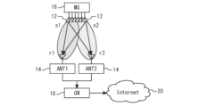
- 2 is a diagram illustrating a generalized configuration of the first embodiment of the present disclosure, in which the satellites illustrated in FIG. 1 are replaced with mobile stations.
- FIG. 3 is a block diagram for functionally explaining the configuration of the mobile station and the terrestrial base station shown in FIG. 2 .
- 4A to 4C are diagrams for explaining a pattern of a radio signal repeatedly transmitted from a transmitting station to a receiving station in the first embodiment of the present disclosure.
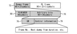
- FIG. 6 is a diagram for explaining details of a dummy frame included in the pattern shown in FIG. 5 .
- FIG. FIG. 2 is a block diagram for explaining characteristic functions of a receiving station according to the first embodiment of the present disclosure.
- 1 is a flowchart for explaining a flow of processing executed in the first embodiment of the present disclosure.
- 9 is a flowchart for explaining the flow of a modified example of the process shown in FIG. 8 .
- FIG. 11 is a block diagram for explaining characteristic functions of a terrestrial base station according to a second embodiment of the present disclosure.
- FIG. 11 is a diagram for explaining a problem to be solved by the second embodiment of the present disclosure.
- Fig. 1 shows a configuration in which a wireless communication system according to a first embodiment of the present disclosure is realized using a satellite and a terrestrial base station.
- the system according to the present embodiment includes a satellite 10.
- the satellite 10 includes a plurality of antennas.
- Fig. 1 shows that the satellite 10 includes three antennas 12-1 to 12-3.
- the subscripts will be omitted and they will be referred to as "antennas 12".
- the system of this embodiment also includes one or more terrestrial antennas.
- FIG. 1 shows an example in which the system of this embodiment includes three terrestrial antennas 14-1 to 14-3.
- these will be referred to as “terrestrial antennas 14" with the subscripts omitted.
- the satellite 10 shown in FIG. 1 may be a LEO satellite.
- a LEO satellite orbits the Earth in a low Earth orbit (LEO), for example, at an altitude of 2,000 km or less.
- LEO low Earth orbit
- GEO geostationary Earth orbit
- the distance between the LEO satellite and the terrestrial antenna 14 is less than one-tenth of that when GEO satellites are used.
- the propagation delay can be significantly reduced compared to a system using GEO satellites.
- the propagation loss is also small. This makes it possible to reduce the power consumption of the transmitting station and to make the transmitting station and terrestrial station smaller, which is expected to reduce equipment costs.
- LEO satellites unlike GEO satellites, are characterized by being constantly moving when viewed from the ground. For this reason, to provide continuous service using LEO satellites, it is necessary to launch multiple satellites and provide comprehensive coverage to the entire service area. In particular, to provide global services, it is essential to deploy a satellite constellation orbiting the Earth.
- FIG. 2 shows a generalized diagram of the configuration of embodiment 1 of the present disclosure, with the satellite 10 shown in FIG. 1 replaced with a moving station (hereinafter, "MS") 16.
- MS 16 can be any mobile station with communication capabilities, including a High Altitude Platform Station (HAPS) that flies at an altitude of about 20 km above the ground.
- HAPS High Altitude Platform Station
- the MS 16 shown in FIG. 2 is equipped with multiple antennas 12, similar to the satellite 10 shown in FIG. 1.
- the MS 16 can transmit different signals individually from each of the multiple antennas 12.
- FIG. 2 shows the antennas 12 sending out signals S1 and S2.
- two terrestrial antennas 14 are communicating with MS 16.
- the terrestrial antenna 14 shown on the left side of the figure is designated as ANT1
- the terrestrial antenna 14 shown on the right side of the figure is designated as ANT2.
- the signal received by ANT1 is designated as signal r1
- the signal received by ANT2 is designated as r2.
- ANT1 and ANT2 can transmit the received signals r1 and r2, respectively, to a terrestrial base station (hereinafter referred to as "Gate Way": "GW”) 18.
- GW 18 can perform processing such as decoding on signals r1 and r2, and then send them out to the Internet line 20.
- FIG. 3 is a block diagram for explaining the functional configuration of MS 16 and GW 18. As shown in FIG. 3, the MS 16 has the following blocks to process the downlink data to be sent to the GW 18:
- “Parallel/serial conversion unit 22” A block that performs parallel/serial conversion of bit information of downlink data. The number of parallel connections is set to the number of connections of the communication targets that are the transmission sources of the downlink data. This number of connections is provided to MS 16 as control information.
- Transmission signal modulation unit 24 a block that modulates a bit string and converts it into an electrical signal.
- Frequency conversion unit 26 a block that converts an electrical signal into a predetermined frequency to be applied to a radio signal sent from the antenna 12.
- “Control information adding unit 28” A block that adds the presence or absence of transmission/reception interference to control information. The presence or absence of transmission/reception interference is determined based on the channel state estimated by a channel estimating unit 34, which will be described later.
- “Signal transmitting unit 30 ” a block for transmitting a received signal from the antenna 12 .
- the MS 16 also has the following blocks for processing uplink data sent from the GW 18: "Signal receiving unit 32": A block for receiving signals that have arrived at the antenna 12. When signals are sent from multiple terrestrial antennas 14 to each antenna 12 at overlapping times, those signals may arrive at the antenna 12 of the MS 12 in a state of interfering with each other. In this case, the signal receiving unit 32 also performs processing for synchronizing those signals. "Channel estimator 34": Based on the signal received by the signal receiver 32, estimates the state of the channel formed between the antenna 12 of the MS 16 and the terrestrial antenna 14. The estimated channel state is provided to the control information assigner 28 as described above.
- Reception interference compensation unit 36 This is a block that performs reception interference compensation to separate signals sent from multiple terrestrial antennas 14 when the signals reach the antenna 12 in a state of mutual interference. The reception interference compensation is performed based on the channel state estimated by the channel estimation unit 34.
- Frequency conversion unit 38 a block for converting a radio signal in a state where the influence of reception interference has been compensated for into an electrical signal of a predetermined frequency.
- Receiveived signal demodulation unit 40 A block that demodulates an electrical signal into a bit string.
- Serial/parallel converter 42 A block that performs serial/parallel conversion on the electrical signal demodulated into a bit string to generate uplink data.
- the number of parallel connections is set to the number of connections of communication targets to which the uplink data is to be transmitted. The number of connections is provided to the MS 16 as control information, as in the case of the parallel/serial converter 22.
- the GW 18 has the following blocks for processing uplink data to be sent to the MS 16: "Parallel/serial conversion unit 44": A block that converts the bit information of uplink data from parallel to serial. The number of parallel connections is set to the number of connections of the communication targets that are the transmission sources of the uplink data. This number of connections is provided to the GW 18 as control information.
- "Transmission signal modulation unit 46” A block that modulates a bit string and converts it into an electrical signal.
- Frequency conversion unit 48 a block that converts an electrical signal into a predetermined frequency to be applied to a radio signal to be transmitted from the ground antenna 14.
- Control information adding unit 50 A block that adds the presence or absence of transmission/reception interference to control information. The presence or absence of transmission/reception interference is determined based on the channel state estimated by a channel estimating unit 56, which will be described later.
- “Signal transmitting unit 52” a block for transmitting the received signal from the ground antenna 14.
- the GW 18 also has the following blocks for processing the downlink data transmitted from the MS 16: "Signal receiving unit 54": a block for receiving signals that have arrived at the terrestrial antenna 14. When signals sent from a plurality of antennas 12 arrive at the terrestrial antenna 14 in a state of interference with each other, the signal receiving unit 54 also executes a process for synchronizing those signals. “Channel estimator 56 ”: Estimates the channel state between the antenna 12 of the MS 16 and the ground antenna 14 based on the signal received by the signal receiver 54 . “Reception interference compensation unit 58”: When signals sent from a plurality of antennas 12 reach the ground antenna 14 in a state of interference with each other, this unit performs reception interference compensation to separate the signals.
- Frequency conversion unit 60 a block for converting a radio signal in a state where the influence of reception interference has been compensated for, into an electrical signal of a predetermined frequency.
- Receiveived signal demodulation unit 62 A block that demodulates an electrical signal into a bit string.
- Serial/parallel converter 64 A block that performs serial/parallel conversion on the electrical signal demodulated into a bit string to generate downlink data.
- the number of parallel connections is set to the number of connections of the communication targets to which the downlink data is to be transmitted. As in the case of the parallel/serial converter 44, the number of connections is provided to the GW 18 as control information.
- the configuration of MS16 and the configuration of GW18 described above can each be realized by combining dedicated hardware with a general computer system.
- a computer system includes a processor such as a CPU, memory devices including ROM, RAM, and hard disks, and various interface devices.
- the functions of MS16 and the functions of GW18 are realized by the respective processors executing programs stored in the respective memory devices.
- wireless communication is established between the MS 16 and the GW 18 by MIMO transmission using multiple antennas 12 and multiple terrestrial antennas 14.
- the MS 16 and the GW 18 realize the above functions by using a communication standard that does not support MIMO transmission.
- the MS 16 and the GW 18 realize the MIMO transmission under the DVB-S2X standard, which is recognized as having high versatility in fields such as satellite communications.
- FIG 4 shows the structure of a communication frame supported by the DVB-S2X standard.
- this frame will be referred to as a "PL frame 66.”
- the PL frame 66 is composed of a PL header 68 and a payload 70.
- the PL header 68 contains 90 symbols.
- the payload 70 contains 90 x S symbols.
- the PL header 68 can be used by storing, for example, a symbol indicating that it is "dummy.” Hereinafter, such a frame will be referred to as a "dummy frame.” On the other hand, a frame that includes a symbol that is not "dummy" in the PL header 68 will be referred to as a "normal frame.” In the DVB-S2X standard, a normal frame is treated as if the data to be exchanged is stored in the payload 70. On the other hand, a dummy frame is treated as if the data to be exchanged is not stored in the payload 70. As a result, after being processed in the channel estimation unit 56, the dummy frame is discarded without being subjected to demodulation or the like.
- FIG. 5 shows the repetition pattern of the radio signal that MS16 transmits to GW18 to achieve MIMO transmission in this embodiment.
- dummy frames 72 and normal frames 74 are transmitted alternately and repeatedly from MS16 to GW18. Note that the repetition pattern shown in FIG. 5 is also used in the radio signal that GW18 transmits to MS16 for MIMO transmission.
- FIG. 6 is a diagram for explaining the details of the dummy frame 72.
- the dummy frame 72 is also a type of PL frame 66 that conforms to the DVB-S2X standard. Therefore, the dummy frame 72 also includes a PL header 68 that includes 90 symbols, and a payload 70 that includes 90 ⁇ S (specifically, 90 ⁇ 37) arbitrary bit symbols.
- the PL header 68 of the dummy frame 72 stores a standard symbol that the DVB-S2X standard defines as "dummy.” Meanwhile, in this embodiment, the payload 70 (arbitrary bit symbol) of the dummy frame 72 stores a unique word (hereinafter, "UW") 76 specific to the source antenna 12 and control information 78.
- UW unique word
- the control information 78 can include a frame number, the period until the next dummy frame, and the like.
- the MS 16 with which the terrestrial antenna 14 communicates changes over time as the MS 16 moves.
- the control information 78 can also include information regarding the combination of the communicating MS 16 and terrestrial antenna 14, and information regarding the channel state between the two.
- the arbitrary bit symbol of the dummy frame 72 that is, the above UW 76 and control information 78, is assigned a signal that is unique to each transmitting antenna 12 and is orthogonal to signals unique to other antennas 12.
- the UW 76 and control information 78 are assigned orthogonal codes such as gold sequences and Walsh codes.
- the arbitrary bit symbol is composed of an orthogonal code
- the GW 18 can extract the UW 76 and control information 78 individually. Then, if the UW 76 can be extracted, it can be determined from which of the multiple antennas 12 the dummy frame 72 containing that symbol was sent.
- GW 18 detects the timing error when the signals sent from each antenna 12 reach each terrestrial antenna 14, and achieves synchronization between the signals based on the result.
- GW 18 can also detect the frequency error by detecting the phase deviation of UW 76. This allows GW 18 to achieve synchronization regarding frequency as well.
- the output value of the correlator that determines the correlation with the orthogonal code also indicates the channel state between the antenna 12 and the terrestrial antenna 14. Therefore, the output value of the correlator can be used as a channel estimation value. Therefore, in this embodiment, the GW 18 can estimate the channel state between the antenna 12 and the terrestrial antenna 14 by analyzing the dummy frame.
- control information 78 is added to the arbitrary bit symbol of the dummy frame 72. And, as described above, this control information 78 includes the frame number and the period until the next dummy frame. By using the frame number, it is possible to correct reception timing errors that exceed the frame length allowed by the receiving station, GW 18. Furthermore, if the time until the next dummy frame is known, it is possible to improve the detection accuracy of the next dummy frame. Therefore, according to the system of this embodiment, it is possible to improve the reception characteristics of GW 18.
- the transmission timing from each antenna 12 may be divided along the time axis, and while one antenna 12 is transmitting a dummy frame 72, the other antennas 12 may be put into a stopped state, thereby detecting specific UWs 76, etc. one by one.
- signals from multiple antennas 12 may be divided along the frequency axis and orthogonalized.
- Fig. 7 is a block diagram for explaining the characteristic functions of the receiving station side of MIMO transmission.
- MS16 is a transmitting station
- GW18 is a receiving station.
- the explanation will be given assuming that Fig. 7 is a block diagram of GW18.
- the GW 18 collects signals (e.g., r1 to r3) received by each of multiple terrestrial antennas 14 (e.g., 14-1 to 14-3). Signals (e.g., r1 to r3) sent from multiple antennas 12 (e.g., 12-1 to 12-39) on the MS 16 side may arrive at each terrestrial antenna 14 in a state of mutual interference. Therefore, each received signal (r1 to r3) may contain overlapping components of multiple transmitted signals (s1 to s3). Such received signals are transmitted to the GW 18 from the multiple terrestrial antennas 14.
- signals e.g., r1 to r3
- signals e.g., r1 to r3 sent from multiple antennas 12 (e.g., 12-1 to 12-39) on the MS 16 side may arrive at each terrestrial antenna 14 in a state of mutual interference. Therefore, each received signal (r1 to r3) may contain overlapping components of multiple transmitted signals (s1 to s3). Such received signals are transmitted to the GW 18 from the multiple terrestrial antenna
- the received signals (r1 to r3) collected in GW 18 are provided to a dummy frame UW correlator 80 and a timing adjuster 82. In the block diagram shown in Figure 3, these are formed inside the signal receiving unit 54.
- the dummy frame UW correlator 80 performs peak value detection using the correlator on the received signals (r1 to r3). If the transmitted signals (s1 to s3) contain dummy frames, the signal components contained in each of the transmitted signals (s1 to s3), i.e., the UW 76 and control information 78, are extracted or estimated from the received signals (r1 to r3).
- the processing result of the dummy frame UW correlator 80 is provided to the timing adjuster 82.
- the timing adjuster 82 uses the processing result of the dummy frame UW correlator 80 to adjust the timing of the received signal.
- the output value of the dummy frame UW correlator 80 is also provided to a channel estimator 84.
- the channel estimator 84 corresponds to the channel estimation unit 56 in the block diagram shown in FIG. 3.
- the output value of the correlator can be used as a channel estimate, as described above.
- the channel estimator 84 Based on the output value, i.e., the channel estimate, the channel estimator 84 generates a channel matrix H that represents the state of the channel between the antenna 12 and the ground antenna 14.
- Information on the generated channel matrix H is provided to the equalizer 86 together with the received signal processed by the timing adjuster 82.
- the equalizer 86 corresponds to the reception interference compensation unit 58 in the block diagram shown in FIG. 3.
- the above-mentioned channel matrix H is a matrix for extracting individual transmission signals (s1 to s3) by multiplying it by a reception signal (r1 to r3) that contains components of multiple transmission signals (s1 to s3).
- the equalizer 86 performs reception interference compensation using the channel matrix H on the reception signals (r1 to r3) that have passed through the timing adjuster 82, and obtains the separated transmission signals (s1 to s3).
- this process will be referred to as "equalization process”.
- the above equalization process is performed using a channel matrix H based on the output value of the dummy frame UW correlator 80.
- the equalizer 86 can use the channel matrix H to perform equalization on normal frames as well.
- the state of the channel between the antenna 12 and the terrestrial antenna 14 changes from moment to moment due to the movement of the MS 16.
- the actual channel state deviates over time from the state represented by the channel matrix H.
- the equalization process of the normal frame 74 is performed based on the channel matrix H acquired based on the dummy frame 72 immediately preceding it.
- the time difference between the timing of acquiring the channel matrix H and the timing of performing the equalization process is extremely small, it is possible to perform highly accurate equalization process on the normal frame 74. Therefore, according to this embodiment, it is possible to achieve extremely accurate MIMO transmission while using a communication standard that does not support MIMO transmission.
- the signal processed by the equalizer 86 is provided to a dummy frame discarder 88.
- the function of the dummy frame discarder 88 is supported by the DVB-S2X standard used in this embodiment. According to this function, frames with a predefined dummy header are discarded as not containing actual data. As a result, in this embodiment, while repeatedly transmitting and receiving dummy frames 72, it is possible to avoid unnecessary demodulation processing and the like being performed on the receiving side for the dummy frames 72.
- the normal frame 74 passes through the dummy frame discarder 88 and is provided to the demodulator 90. Thereafter, the GW 18 performs the processing required to generate downlink data on only the normal frame 74. As a result, MIMO transmission with good communication quality is achieved without unnecessary calculation processing.
- the dummy frame discarder 88 and demodulator 90 shown in FIG. 7 are functions built into existing modems used under the DVB-S2X standard. In the block diagram shown in FIG. 3, these are formed inside the reception interference compensation unit 58, the frequency conversion unit 60, or the reception signal demodulation unit 62.
- FIG. 8 is a flowchart for explaining the flow of processing performed by each of the transmitting station and the receiving station in this embodiment to realize the above functions. As with the explanation of FIG. 7, the following explanation will be given using an example in which the MS16 is the transmitting station and the GW18 is the receiving station.
- MS 16 When the transmitting station, MS 16, recognizes the occurrence of downlink data to be transmitted to GW 18 (step 100), it generates a normal frame 74 with that data stored in the payload 70.
- a dummy frame 72 is inserted before the normal frame 74 (step 102).
- a specified symbol that means "dummy” is stored in the PL header 68 of the dummy frame 72.
- the UW 76 and control information 78 are added to the arbitrary bit symbol of the dummy frame 72 (step 104). At this point, it has been determined which of the multiple antennas 12 will be the current transmitting antenna.
- the UW 76 and control information 78 are then composed of an orthogonal code unique to the antenna 12 used as the transmitting antenna.
- step 106 data modulation, frequency conversion, transmission, and other processes are carried out in sequence, and the dummy frame 72 and normal frame 74 are transmitted in that order from the transmitting antenna (step 106).
- the above process may be performed in parallel for multiple antennas 12. In other words, if there is only one piece of data to be transmitted, the above process transmits a radio signal from only one antenna 12. On the other hand, if there is multiple pieces of data to be transmitted, a set of a dummy frame 72 and a normal frame 74 may be transmitted from each antenna 12, and multiple sets of radio signals may be transmitted simultaneously using multiple antennas 12.
- the signals transmitted from the MSs 16 are collected at the receiving station, GW 18, via multiple terrestrial antennas 14.
- the GW 18 receives these signals and performs processing such as frequency conversion (step 110).
- GW18 performs peak value detection on the received signal using a correlator. Then, it performs processing to synchronize the signal based on UW76 extracted by the peak value detection (step 112).
- GW18 extracts the control information 78 contained in the dummy frame 72 based on the result of the peak value detection (step 114).
- GW18 also obtains channel estimates from the output values of the peak value detection and generates a channel matrix H that represents the current channel state. Then, GW18 uses the channel matrix H to perform reception interference compensation for the received signal (step 116).
- the GW 18 discards the dummy frames (step 118), and performs processing such as data demodulation only on the normal frames 74 (step 120).
- this embodiment realizes communication using MIMO transmission by appropriately using a standard that does not support MIMO transmission. Therefore, according to this embodiment, it is possible to implement MIMO transmission functionality in a system that uses a highly versatile standard such as DVB-S2X.
- the MS 16 functions as a transmitting station and the GW 18 functions as a receiving station.
- the present disclosure is not limited to this. According to the method of the present embodiment, it is also possible to make the GW 18 function as a transmitting station and the MS 16 function as a receiving station.
- multiple transmission signals from a transmitting station interfere with each other when they reach a receiving station, and the receiving station performs reception interference compensation to separate these signals.
- the transmitting station can grasp the channel state in advance, it is possible to cause transmission signals to reach each of the receiving antennas without interference by performing precoding on the transmission signals.
- MIMO transmission can be realized in a manner that does not require reception interference compensation by the receiving station.
- FIG. 9 is a flowchart for explaining the flow of processing performed by the transmitting station and the receiving station to achieve MIMO transmission using the transmit precoding technique. Note that the following explanation, like the explanation of the flowchart shown in FIG. 8, will be given using an example in which the MS 16 functions as the transmitting station and the GW 18 functions as the receiving station. Also, in FIG. 9, steps that are the same as those shown in FIG. 8 are given the same reference numerals, and their explanations will be omitted or simplified.
- the transmitting station performs processing to obtain a channel estimation value (step 122). If the receiving station has already performed channel estimation, in this step 122, it accepts notification of the result from the receiving station. On the other hand, if the receiving station has not yet performed channel estimation, it cannot receive notification of the channel estimation, and so proceeds to the next step.
- a channel matrix H corresponding to the channel estimation value is calculated.
- transmit precoding is performed by multiplying the transmit signal by a weighting matrix W based on the channel matrix H (step 124).
- step 122 if a channel estimation value cannot be obtained in step 122, precoding cannot be applied to the transmission signal. Therefore, in this case, after steps 104 and 106, a signal that has not been subjected to transmission precoding is transmitted, as in the case shown in FIG. 8.
- each of the multiple terrestrial antennas 14 receives a signal that is not affected by interference.
- the GW 18 performs the processing of steps 112 and 114 on those received signals. Since there is no need to perform reception interference compensation, step 116 is skipped.
- GW18 performs channel estimation using the received signal (step 126).
- the result of the channel estimation is notified to MS16, which is the transmitting station (step 128).
- GW18 may notify MS16 of this result directly, or may notify MS16 via an external control station.
- steps 110 to 116 are executed for the received signal that is affected by interference, as in the case shown in FIG. 8. Then, as a result of the reception interference compensation, the signal from which the individual signal components have been separated is used to execute step 126. This makes it possible for the transmitting station to subsequently implement transmission precoding.
- the channel estimation is always performed in the receiving station, and the transmitting station acquires the channel estimation value upon receiving a notification from the receiving station.
- the method by which the transmitting station acquires the channel estimation value is not limited to this.
- the transmitting station may acquire the channel estimation value in the following procedure. (1) A dummy frame 72 to which an orthogonal code is assigned is transmitted from each of a plurality of terrestrial antennas 14 toward the MS 16 . (2) The MS 16 performs peak value detection using a dummy frame UW correlator to extract the transmission signals from each of the terrestrial antennas 14. Each of the extracted transmission signals is used as a pilot signal emitted from each of the multiple terrestrial antennas 14 to calculate a channel estimation value.
- Embodiment 2 [Configuration of the Second Embodiment] Next, a second embodiment of the present disclosure will be described with reference to FIGS.
- the wireless communication system according to the second embodiment of the present disclosure is similar to that of the first embodiment, except that the internal structure of the receiving station is changed from the structure shown in Fig. 7 to the structure shown in Fig. 10.
- the following description will focus on the parts unique to the wireless communication system according to the present embodiment.
- the dummy frame UW correlator 80 shown in FIG. 7 is replaced with a dummy frame UW correlator 92.
- a PL header correlator 94 is added to the configuration shown in FIG. 7.
- the configuration shown in FIG. 10 is the same as the configuration shown in FIG. 7 except for the above two points.
- Fig. 11 is a diagram for explaining a problem involved in the wireless communication system of the embodiment 1. More specifically, Fig. 11 shows three dummy frames 72-1 to 72-3 simultaneously transmitted from three antennas 12 equipped in the MS 16.
- the dummy frames 72-1 to 72-3 are each assigned a UW1 to UW3 that is unique to the antenna 12 from which they are sent. These are composed of orthogonal codes, so even if the three dummy frames 72-1 to 72-3 are sent simultaneously, their mutual relationships can be controlled to a combination of 1s and 0s. Therefore, even if multiple signals interfere with each other, there will be no excessive reinforcement.
- the PL header 68 must be composed of a specified symbol that indicates a dummy, and so it is the same for all dummy frames 72-1 to 72-3. For this reason, if they are sent simultaneously, the multiple signals will reinforce each other due to their phase relationships, and the received power may become locally excessive.
- the PL header correlator 94 provided in the GW 18 shown in FIG. 10 receives received signals from multiple terrestrial antennas 14 and detects the correlation state of the PL headers contained in the simultaneously received signals. If reinforcement exceeding a threshold is found in the PL header, it determines that excessive overlap of the dummy frame 72 is occurring and outputs a Disable signal to the dummy frame UW correlator 92. On the other hand, if reinforcement exceeding a threshold is not found in the PL header, the PL header correlator 94 outputs an Enable signal to the dummy frame UW correlator 92.
- the dummy frame UW correlator 92 in this embodiment stops accepting received signals when a Disable signal is input, and proceeds with peak detection processing only when an Enable signal is input. For this reason, in this embodiment, the dummy frame UW correlator 92 performs peak detection only under circumstances in which multiple received signals are not excessively reinforcing each other and UW 76 can be correctly detected. As a result, according to this embodiment, erroneous detection of UW 76, etc. can be prevented, and even higher quality MIMO transmission can be achieved compared to embodiment 1.
- a LEO satellite and a HAPS are given as examples of the MS 16, but the MS 16 is not limited to these.
- a wireless communication device that moves on the ground such as a portable terminal, may be used as the MS 16.
Landscapes
- Engineering & Computer Science (AREA)
- Computer Networks & Wireless Communication (AREA)
- Signal Processing (AREA)
- Radio Transmission System (AREA)
Priority Applications (2)
| Application Number | Priority Date | Filing Date | Title |
|---|---|---|---|
| PCT/JP2023/020681 WO2024247261A1 (ja) | 2023-06-02 | 2023-06-02 | 無線通信システム、無線通信装置、無線通信方法および無線通信用プログラム |
| JP2025523201A JPWO2024247261A1 (https=) | 2023-06-02 | 2023-06-02 |
Applications Claiming Priority (1)
| Application Number | Priority Date | Filing Date | Title |
|---|---|---|---|
| PCT/JP2023/020681 WO2024247261A1 (ja) | 2023-06-02 | 2023-06-02 | 無線通信システム、無線通信装置、無線通信方法および無線通信用プログラム |
Publications (1)
| Publication Number | Publication Date |
|---|---|
| WO2024247261A1 true WO2024247261A1 (ja) | 2024-12-05 |
Family
ID=93657558
Family Applications (1)
| Application Number | Title | Priority Date | Filing Date |
|---|---|---|---|
| PCT/JP2023/020681 Ceased WO2024247261A1 (ja) | 2023-06-02 | 2023-06-02 | 無線通信システム、無線通信装置、無線通信方法および無線通信用プログラム |
Country Status (2)
| Country | Link |
|---|---|
| JP (1) | JPWO2024247261A1 (https=) |
| WO (1) | WO2024247261A1 (https=) |
Citations (4)
| Publication number | Priority date | Publication date | Assignee | Title |
|---|---|---|---|---|
| JPH08195703A (ja) * | 1995-01-17 | 1996-07-30 | Toshiba Corp | 無線通信装置 |
| JP2002141865A (ja) * | 2000-09-06 | 2002-05-17 | Lucent Technol Inc | 通信方法 |
| WO2015087703A1 (ja) * | 2013-12-09 | 2015-06-18 | ソニー株式会社 | データ処理装置、及び、データ処理方法 |
| WO2015177779A1 (en) * | 2014-05-20 | 2015-11-26 | Satixfy Ltd. | A method for reducing interference in a satellite communications network |
-
2023
- 2023-06-02 JP JP2025523201A patent/JPWO2024247261A1/ja active Pending
- 2023-06-02 WO PCT/JP2023/020681 patent/WO2024247261A1/ja not_active Ceased
Patent Citations (4)
| Publication number | Priority date | Publication date | Assignee | Title |
|---|---|---|---|---|
| JPH08195703A (ja) * | 1995-01-17 | 1996-07-30 | Toshiba Corp | 無線通信装置 |
| JP2002141865A (ja) * | 2000-09-06 | 2002-05-17 | Lucent Technol Inc | 通信方法 |
| WO2015087703A1 (ja) * | 2013-12-09 | 2015-06-18 | ソニー株式会社 | データ処理装置、及び、データ処理方法 |
| WO2015177779A1 (en) * | 2014-05-20 | 2015-11-26 | Satixfy Ltd. | A method for reducing interference in a satellite communications network |
Non-Patent Citations (1)
| Title |
|---|
| DAISUKE GOTO , KIYOHIKO ITOKAWA , FUMIHIRO YAMASHITA , TOMOYA KATO , MITSUHIRO NAKADAI : "B-3-20: Evaluation of successive interference cancellation for channel capacity improvements in 3x3 LEO-MIMO systems", PROCEEDINGS 1 OF THE 2022 COMMUNICATION SOCIETY CONFERENCE OF IEICE, IEICE, JP, 23 August 2022 (2022-08-23), JP, pages 164, XP009559230 * |
Also Published As
| Publication number | Publication date |
|---|---|
| JPWO2024247261A1 (https=) | 2024-12-05 |
Similar Documents
| Publication | Publication Date | Title |
|---|---|---|
| US7139527B2 (en) | Multi point wireless transmission repeater system and wireless equipments | |
| KR101468882B1 (ko) | 무선 통신 네트워크들에서 다중 중계국들과 협동 중계를 위한 방법 및 디바이스 | |
| US10090945B2 (en) | MIMO communication system of transmitting and receiving pilot signals to estimate a channel | |
| JP5661120B2 (ja) | 無線ネットワークにおけるダウンリンク・マルチユーザーmimo送信のための方法および装置 | |
| US12580636B2 (en) | Selection of decoding level at signal forwarding devices | |
| US10912059B2 (en) | Systems, devices and methods for communicating data with unmanned aerial vehicles using underlay broadcast channel | |
| Kisseleff et al. | Centralized gateway concept for precoded multi-beam GEO satellite networks | |
| CN115001560B (zh) | 一种基于功率域非正交多址接入的星地融合中继网络传输方法 | |
| WO2011035797A1 (en) | Method, relay station and system for transmitting signals between a first signal source and a second signal source | |
| US8543147B2 (en) | Radio communication system, transmission system, radio terminal and radio communication method | |
| US12207210B2 (en) | Receiving method, wireless communication method, receiving station, wireless communication system, and receiving program | |
| US7319822B2 (en) | System and method of space-time equalization to mitigate effects of fading and scintillation for wireless communication | |
| WO2017147972A1 (en) | Frame structure for a physical control channel | |
| WO2024247261A1 (ja) | 無線通信システム、無線通信装置、無線通信方法および無線通信用プログラム | |
| EP4346108B1 (en) | Method and apparatus for transmitting an uplink signal based on doppler frequency variation | |
| WO2024065750A1 (zh) | 能力信息的上报方法、装置、设备及存储介质 | |
| US11456897B2 (en) | Communication apparatus, method, program, and recording medium | |
| KR101405498B1 (ko) | 중계 방식의 무선통신 시스템에서 시공간 부호화 장치 및방법 | |
| CN116614166B (zh) | 多个多天线卫星之上的混合mimo | |
| KR101563465B1 (ko) | 고화질 서비스 전송을 위한 miso-ofdm 기반의 협력 통신 시스템 및 그것을 이용한 협력 통신 방법 | |
| WO2025257904A1 (ja) | 無線通信システム、無線通信装置、無線通信方法および無線通信用プログラム装置 | |
| CN120185694B (zh) | 数据发送、接收方法及装置、存储介质、电子设备 | |
| EP4443823A1 (en) | Method of performing enhanced channel estimation in non-terrestrial network-based communication system and device thereof | |
| JP7701179B2 (ja) | 復調装置、基地局および復調方法 | |
| WO2024247234A1 (ja) | 無線通信システム、無線通信装置、無線通信方法および無線通信用プログラム |
Legal Events
| Date | Code | Title | Description |
|---|---|---|---|
| 121 | Ep: the epo has been informed by wipo that ep was designated in this application |
Ref document number: 23939733 Country of ref document: EP Kind code of ref document: A1 |
|
| ENP | Entry into the national phase |
Ref document number: 2025523201 Country of ref document: JP Kind code of ref document: A |
|
| NENP | Non-entry into the national phase |
Ref country code: DE |