WO2024242140A1 - 運転支援装置、運転支援システム、運転支援方法および運転支援プログラム - Google Patents
運転支援装置、運転支援システム、運転支援方法および運転支援プログラム Download PDFInfo
- Publication number
- WO2024242140A1 WO2024242140A1 PCT/JP2024/018857 JP2024018857W WO2024242140A1 WO 2024242140 A1 WO2024242140 A1 WO 2024242140A1 JP 2024018857 W JP2024018857 W JP 2024018857W WO 2024242140 A1 WO2024242140 A1 WO 2024242140A1
- Authority
- WO
- WIPO (PCT)
- Prior art keywords
- estimated value
- amount
- aqueous solution
- calculation unit
- driving assistance
- Prior art date
- Legal status (The legal status is an assumption and is not a legal conclusion. Google has not performed a legal analysis and makes no representation as to the accuracy of the status listed.)
- Ceased
Links
Images









Classifications
-
- C—CHEMISTRY; METALLURGY
- C25—ELECTROLYTIC OR ELECTROPHORETIC PROCESSES; APPARATUS THEREFOR
- C25B—ELECTROLYTIC OR ELECTROPHORETIC PROCESSES FOR THE PRODUCTION OF COMPOUNDS OR NON-METALS; APPARATUS THEREFOR
- C25B15/00—Operating or servicing cells
- C25B15/02—Process control or regulation
- C25B15/023—Measuring, analysing or testing during electrolytic production
-
- C—CHEMISTRY; METALLURGY
- C25—ELECTROLYTIC OR ELECTROPHORETIC PROCESSES; APPARATUS THEREFOR
- C25B—ELECTROLYTIC OR ELECTROPHORETIC PROCESSES FOR THE PRODUCTION OF COMPOUNDS OR NON-METALS; APPARATUS THEREFOR
- C25B1/00—Electrolytic production of inorganic compounds or non-metals
- C25B1/01—Products
- C25B1/02—Hydrogen or oxygen
- C25B1/04—Hydrogen or oxygen by electrolysis of water
-
- C—CHEMISTRY; METALLURGY
- C25—ELECTROLYTIC OR ELECTROPHORETIC PROCESSES; APPARATUS THEREFOR
- C25B—ELECTROLYTIC OR ELECTROPHORETIC PROCESSES FOR THE PRODUCTION OF COMPOUNDS OR NON-METALS; APPARATUS THEREFOR
- C25B1/00—Electrolytic production of inorganic compounds or non-metals
- C25B1/01—Products
- C25B1/34—Simultaneous production of alkali metal hydroxides and chlorine, oxyacids or salts of chlorine, e.g. by chlor-alkali electrolysis
-
- C—CHEMISTRY; METALLURGY
- C25—ELECTROLYTIC OR ELECTROPHORETIC PROCESSES; APPARATUS THEREFOR
- C25B—ELECTROLYTIC OR ELECTROPHORETIC PROCESSES FOR THE PRODUCTION OF COMPOUNDS OR NON-METALS; APPARATUS THEREFOR
- C25B1/00—Electrolytic production of inorganic compounds or non-metals
- C25B1/01—Products
- C25B1/34—Simultaneous production of alkali metal hydroxides and chlorine, oxyacids or salts of chlorine, e.g. by chlor-alkali electrolysis
- C25B1/46—Simultaneous production of alkali metal hydroxides and chlorine, oxyacids or salts of chlorine, e.g. by chlor-alkali electrolysis in diaphragm cells
-
- C—CHEMISTRY; METALLURGY
- C25—ELECTROLYTIC OR ELECTROPHORETIC PROCESSES; APPARATUS THEREFOR
- C25B—ELECTROLYTIC OR ELECTROPHORETIC PROCESSES FOR THE PRODUCTION OF COMPOUNDS OR NON-METALS; APPARATUS THEREFOR
- C25B15/00—Operating or servicing cells
-
- C—CHEMISTRY; METALLURGY
- C25—ELECTROLYTIC OR ELECTROPHORETIC PROCESSES; APPARATUS THEREFOR
- C25B—ELECTROLYTIC OR ELECTROPHORETIC PROCESSES FOR THE PRODUCTION OF COMPOUNDS OR NON-METALS; APPARATUS THEREFOR
- C25B15/00—Operating or servicing cells
- C25B15/02—Process control or regulation
-
- C—CHEMISTRY; METALLURGY
- C25—ELECTROLYTIC OR ELECTROPHORETIC PROCESSES; APPARATUS THEREFOR
- C25B—ELECTROLYTIC OR ELECTROPHORETIC PROCESSES FOR THE PRODUCTION OF COMPOUNDS OR NON-METALS; APPARATUS THEREFOR
- C25B15/00—Operating or servicing cells
- C25B15/02—Process control or regulation
- C25B15/023—Measuring, analysing or testing during electrolytic production
- C25B15/025—Measuring, analysing or testing during electrolytic production of electrolyte parameters
- C25B15/027—Temperature
-
- C—CHEMISTRY; METALLURGY
- C25—ELECTROLYTIC OR ELECTROPHORETIC PROCESSES; APPARATUS THEREFOR
- C25B—ELECTROLYTIC OR ELECTROPHORETIC PROCESSES FOR THE PRODUCTION OF COMPOUNDS OR NON-METALS; APPARATUS THEREFOR
- C25B15/00—Operating or servicing cells
- C25B15/02—Process control or regulation
- C25B15/023—Measuring, analysing or testing during electrolytic production
- C25B15/025—Measuring, analysing or testing during electrolytic production of electrolyte parameters
- C25B15/029—Concentration
-
- C—CHEMISTRY; METALLURGY
- C25—ELECTROLYTIC OR ELECTROPHORETIC PROCESSES; APPARATUS THEREFOR
- C25B—ELECTROLYTIC OR ELECTROPHORETIC PROCESSES FOR THE PRODUCTION OF COMPOUNDS OR NON-METALS; APPARATUS THEREFOR
- C25B9/00—Cells or assemblies of cells; Constructional parts of cells; Assemblies of constructional parts, e.g. electrode-diaphragm assemblies; Process-related cell features
-
- C—CHEMISTRY; METALLURGY
- C25—ELECTROLYTIC OR ELECTROPHORETIC PROCESSES; APPARATUS THEREFOR
- C25B—ELECTROLYTIC OR ELECTROPHORETIC PROCESSES FOR THE PRODUCTION OF COMPOUNDS OR NON-METALS; APPARATUS THEREFOR
- C25B9/00—Cells or assemblies of cells; Constructional parts of cells; Assemblies of constructional parts, e.g. electrode-diaphragm assemblies; Process-related cell features
- C25B9/17—Cells comprising dimensionally-stable non-movable electrodes; Assemblies of constructional parts thereof
- C25B9/19—Cells comprising dimensionally-stable non-movable electrodes; Assemblies of constructional parts thereof with diaphragms
Definitions
- the present invention relates to a driving assistance device, a driving assistance system, a driving assistance method, and a driving assistance program.
- Patent Document 1 states that "the current calculation unit 55 calculates the current that maximizes the production amount Pa of the product P produced by the multiple electrolytic cells 90 during the period T" (paragraph 0093).
- Japanese Patent Laid-Open No. 2006-133633 states that "the estimation unit estimates the performance degradation rate based on the concentration profile” (claim 1).
- Patent Documents [Patent Documents] [Patent Document 1] International Publication No. 2022/191082 [Patent Document 2] Japanese Patent No. 7182025
- the nature of the performance change in the electrolytic performance of the electrolytic device may differ from the actual performance change. For this reason, it may be difficult to adjust the operating conditions of the electrolytic cell based on the actual performance change in the electrolytic performance of the electrolytic device.
- a driving assistance device in a first aspect of the present invention, includes a calculation unit that calculates the operating conditions of an electrolytic cell based on a first estimated value of a performance change in the electrolytic performance of the electrolytic cell.
- the driving assistance device may further include an estimation unit that estimates a second estimated value of the performance change based on a first driving condition, which is the driving condition calculated by the calculation unit.
- the calculation unit may calculate, based on the second estimated value, a second operating condition that is an operating condition under which the amount of power consumed by the electrolytic cell in a predetermined fixed period of time is a predetermined amount of power, or the amount of product produced by the electrolytic cell in a predetermined fixed period of time is a predetermined production amount.
- the calculation unit may calculate the first power consumption amount based on the first estimated value, and may calculate the second power consumption amount based on the second estimated value. If the second power consumption amount is smaller than the first power consumption amount, the estimation unit may estimate a third estimated value of the performance change.
- the calculation unit may calculate the first production amount based on the first estimated value, and may calculate the second production amount based on the second estimated value. If the second production amount is larger than the first production amount, the estimation unit may estimate a third estimated value of the performance change.
- the calculation unit may correct the second operating condition based on the first estimated value and the first actual value of the performance change.
- the estimation unit may estimate the production amount.
- the calculation unit may correct the second operating condition based on the estimated production amount and the actual production amount.
- Any of the above driving assistance devices may further include a selection unit that selects a candidate based on the first estimated value for each candidate driving condition such that the amount of power consumed by the electrolytic cell in a predetermined fixed period of time is a predetermined amount of power, or the amount of product produced by the electrolytic cell in a predetermined period of time is a predetermined production amount.
- the calculation unit may calculate the cost associated with operating the electrolytic cell.
- the calculation unit may calculate a second operating condition, which is an operating condition under which the cost in a predetermined fixed period of time becomes a predetermined cost, based on the second estimated value.
- the calculation unit may calculate a first cost based on the first estimated value, and calculate a second cost based on the second estimated value. If the second cost is smaller than the first cost, the estimation unit may estimate a third estimated value of the performance change.
- the calculation unit may correct the second driving condition based on the first estimated value and the first actual value of the performance change.
- Any of the above driving assistance devices may further include a selection unit that selects a candidate for which the cost associated with operating the electrolytic cell for a predetermined period of time is a predetermined cost, based on the first estimated value for each candidate driving condition.
- the certain period may include a plurality of periods including a first period and a second period subsequent to the first period.
- the calculation unit may calculate a plurality of first operating conditions for each of the plurality of periods based on the first estimated value.
- the estimation unit may estimate a second estimated value of the performance change based on the plurality of first operating conditions.
- the estimation unit may estimate a second estimated value of the performance change for each of the plurality of periods based on the first operating condition for each of the plurality of periods.
- the operating conditions may include a plurality of parameters related to the operation of the electrolytic cell.
- the calculation unit may calculate one of the plurality of parameters as the first operating condition based on the first estimated value.
- the calculation unit may calculate a first setting value of another parameter among the multiple parameters based on the first estimated value, and may calculate one parameter based on the calculated first setting value.
- the electrolytic cell may have an ion exchange membrane and an anode chamber and a cathode chamber separated by the ion exchange membrane.
- a first aqueous solution of an alkali metal chloride may be introduced into the anode chamber, and a second aqueous solution of an alkali metal hydroxide may be introduced into the cathode chamber.
- a third aqueous solution of an alkali metal chloride may be derived from the anode chamber, and a fourth aqueous solution of an alkali metal hydroxide may be derived from the cathode chamber.
- the other parameters may be at least one of the salt concentration of the first aqueous solution, the alkali concentration of the second aqueous solution, the salt concentration of the third aqueous solution, the alkali concentration of the fourth aqueous solution, the flow rate of the first aqueous solution, the flow rate of the second aqueous solution, the flow rate of the third aqueous solution, the flow rate of the fourth aqueous solution, the temperature of the aqueous solution of the alkali metal chloride in the anode chamber, and the temperature of the aqueous solution of the alkali metal hydroxide in the cathode chamber.
- the calculation unit may calculate a parameter so that the alkali concentration of the fourth aqueous solution during a predetermined period of time becomes a predetermined concentration.
- the calculation unit may calculate, based on the first estimated value, a parameter that results in a predetermined amount of power being consumed by the electrolytic cell in a predetermined period of time, or a predetermined amount of production of a product produced by the electrolytic cell in a predetermined period of time.
- the calculation unit may further calculate the cost associated with operating the electrolytic cell, and calculate a parameter that results in a predetermined cost over a predetermined period of time based on the first estimated value.
- the one parameter may be a first current supplied to the electrolytic cell.
- the calculation unit may calculate the first current as the first operating condition based on the first estimated value.
- the calculation unit may calculate a first current as a first driving condition based on the first estimated value.
- the estimation unit may estimate a second estimated value based on the first current.
- the calculation unit may calculate a second current as a second driving condition based on the second estimated value.
- the calculation unit may correct the first operating condition based on the second actual value of the performance change when the electrolytic cell is operated under the first operating condition and the second estimated value.
- the electrolytic cell may have an ion exchange membrane and a gasket that holds the ion exchange membrane.
- the change in electrolysis performance may be a change in performance of the ion exchange membrane or a change in performance of the gasket.
- the estimation unit may estimate the first estimated value based on an actual value of impurity data related to the accumulation rate of impurities in the ion exchange membrane, or based on an actual value of the amount of elastic deformation of the gasket.
- the actual value of the impurity data may include an actual value of the accumulation rate or an actual value of the accumulation amount of one or more elements constituting the one or more impurities accumulating in the ion exchange membrane.
- the estimation unit may estimate one or more impurities based on the actual value of the accumulation rate or the actual value of the accumulation amount of the one or more elements, and may estimate a first estimate value based on the estimated accumulation rate or accumulation amount of the one or more impurities.
- the electrolytic cell may have an anode chamber and a cathode chamber separated by an ion exchange membrane.
- An aqueous solution of an alkali metal chloride may be introduced into the anode chamber.
- the impurity data may include concentration data of impurities in the aqueous solution of the alkali metal chloride.
- the estimation unit may estimate the first estimate based on the concentration data of the impurities.
- the electrolytic cell may have an ion exchange membrane, an anode chamber and a cathode chamber separated by the ion exchange membrane, an anode disposed in the anode chamber, and a cathode disposed in the cathode chamber.
- the surfaces of the anode and cathode may be coated with a metal coating agent.
- the change in electrolytic performance may be a performance change based on the remaining amount of coating agent on the surface of the anode or the surface of the cathode.
- the estimation unit may estimate the first estimated value based on the remaining amount of coating agent.
- the estimation unit may estimate the remaining amount of coating agent based on actual values of the types and amounts of elements contained in the coating agent.
- the operating conditions may include a plurality of parameters related to the operation of the electrolytic cell.
- the calculation unit may calculate a first setting value for another parameter among the plurality of parameters based on the first estimated value, and may calculate one parameter among the plurality of parameters based on the calculated first setting value.
- the first parameter may be a current supplied to the electrolytic cell.
- the calculation unit may calculate the first current based on a first set value.
- the electrolytic cell may have an anode chamber and a cathode chamber separated by an ion exchange membrane.
- a first aqueous solution of an alkali metal chloride may be introduced into the anode chamber.
- a second aqueous solution of an alkali metal hydroxide may be introduced into the cathode chamber.
- a third aqueous solution of an alkali metal chloride may be derived from the anode chamber.
- a fourth aqueous solution of an alkali metal hydroxide may be derived from the cathode chamber.
- the other parameters may be at least one of the salt concentration of the first aqueous solution, the alkali concentration of the second aqueous solution, the salt concentration of the third aqueous solution, the alkali concentration of the fourth aqueous solution, the flow rate of the first aqueous solution, the flow rate of the second aqueous solution, the flow rate of the third aqueous solution, the flow rate of the fourth aqueous solution, the temperature of the aqueous solution of the alkali metal chloride in the anode chamber, and the temperature of the aqueous solution of the alkali metal hydroxide in the cathode chamber.
- the calculation unit may calculate the first current so that the alkali concentration of the fourth aqueous solution during a predetermined period of time becomes a predetermined concentration.
- the calculation unit may calculate, for each of the multiple electrolytic cells, a first current that causes the total power consumption of the multiple electrolytic cells in a predetermined period to be a predetermined amount of power, or causes the total production amount of products produced by the multiple electrolytic cells in a predetermined period to be a predetermined production amount, based on the first estimated value for each of the multiple electrolytic cells.
- the calculation unit may further calculate the cost associated with the operation of the multiple electrolytic cells, and calculate, for each of the multiple electrolytic cells, a first current that results in a predetermined cost in a predetermined period based on the first estimated value for each of the multiple electrolytic cells.
- Any of the driving assistance devices described above may further include an estimation unit that estimates a second estimated value of performance degradation based on the driving conditions calculated by the calculation unit.
- the estimation unit may estimate a second estimated value based on the calculated first current.
- the calculation unit may calculate a second setting value of another parameter based on the second estimated value, and calculate the second current based on the calculated second setting value.
- the calculation unit may calculate, for each of the multiple electrolytic cells, a second current that results in a total power consumption during a period of time being a predetermined amount of power, or a total production amount during a period of time being a predetermined production amount, based on the second estimated value for each of the multiple electrolytic cells.
- the calculation unit may calculate a first total power consumption based on the first estimated value, and may calculate a second total power consumption based on the second estimated value. If the second total power consumption is smaller than the first total power consumption, the estimation unit may estimate a third estimated value of performance degradation.
- the calculation unit may calculate a first total production amount based on the first estimated value, and may calculate a second total production amount based on the second estimated value. If the second total production amount is greater than the first total production amount, the estimation unit may estimate a third estimated value of performance degradation.
- the calculation unit may correct the driving conditions based on the first estimated value and the actual value of performance degradation.
- the estimation unit may estimate the total production amount.
- the calculation unit may correct the driving conditions based on the estimated total production amount and the actual value of the total production amount.
- Any of the driving assistance devices described above may further include a selection unit that selects a candidate for which the total power consumption in a predetermined period is a predetermined amount of power, or the total production amount in a predetermined period is a predetermined production amount, based on the first estimated value for each candidate driving condition.
- Any of the driving assistance devices described above may further include an estimation unit that estimates a second estimated value of performance degradation based on the driving conditions calculated by the calculation unit.
- the estimation unit may estimate a second estimated value for each of the multiple electrolytic cells based on the calculated first current.
- the calculation unit may calculate a second current for each of the multiple electrolytic cells, at which the cost in a period of time is a predetermined cost, based on the second estimated value for each of the multiple electrolytic cells.
- the calculation unit may calculate a first cost based on the first estimated value, and may calculate a second cost based on the second estimated value. If the second cost is smaller than the first cost, the estimation unit may estimate a third estimated value of performance degradation.
- the calculation unit may correct the driving conditions based on the first estimated value and the actual value of performance degradation.
- Any of the driving assistance devices described above may further include a selection unit that selects a candidate whose cost in a period of time is a predetermined cost based on the first estimated value for each candidate driving condition.
- the estimation unit may estimate the first estimated value based on an actual value of impurity data relating to the accumulation rate of impurities in the ion exchange membrane.
- the actual value of the impurity data may include an actual value of the accumulation rate or an actual value of the accumulation amount of one or more elements constituting the one or more impurities accumulating in the ion exchange membrane.
- the estimation unit may estimate one or more impurities based on the actual value of the accumulation rate or the actual value of the accumulation amount of the one or more elements, and may estimate a first estimate value based on the estimated accumulation rate or accumulation amount of the one or more impurities.
- the electrolytic cell may have an anode chamber and a cathode chamber separated by an ion exchange membrane.
- An aqueous solution of an alkali metal chloride may be introduced into the anode chamber.
- the impurity data may include concentration data of impurities in the aqueous solution of the alkali metal chloride.
- the estimation unit may estimate the first estimate based on the concentration data of the impurities.
- a driving assistance system in a second aspect of the present invention, includes a driving assistance device and an electrolytic cell.
- an operation assistance method includes a calculation step in which a calculation unit calculates the operating conditions of the electrolytic cell based on a first estimated value of a performance change in the electrolytic performance of the electrolytic cell.
- the driving assistance method may further include an estimation step in which the estimation unit estimates a second estimated value of the performance change based on the driving conditions calculated in the calculation step.
- a driving assistance program causes a computer to function as a driving assistance device or a driving assistance system.
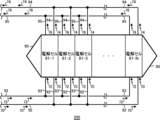
- FIG. 1 illustrates an example of an electrolysis device 200 according to an embodiment of the present invention.
- FIG. 2 is a diagram showing an example of one electrolytic cell 90 in FIG. 1.
- FIG. 3 is a diagram showing an example of details of one electrolysis cell 91 in FIG. 2.
- 4 is a view of the ion exchange membrane 84 in FIG. 3 as viewed in the Y-axis direction. 4 is an enlarged view of the vicinity of an ion exchange membrane 84 in the electrolysis cell 91 shown in FIG. 3.
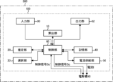
- 1 is a block diagram of a driving assistance device 100 according to an embodiment of the present invention and a diagram showing an example of a driving assistance system 300. [0023] FIG.
- FIG. 10 is a diagram showing an example of the relationship between the accumulation amount of an impurity Im and the current efficiency CE for each impurity Im.
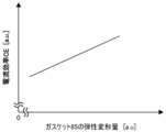
- FIG. 13 is a diagram showing an example of the relationship between the elastic deformation amount of a gasket 85 and current efficiency CE.
- FIG. 13 is a diagram showing an example of the relationship between the remaining amount of metal coating agent on the surface of the cathode 82 and the surface of the anode 80 and the voltage CV of the electrolytic cell 90 for each material of the coating agent.
- FIG. 13 is a diagram showing an example of a first set value Vs1 of the parameter Pr2 when there are multiple electrolytic baths 90.
- FIG. 13 is a diagram showing another example of the first set value Vs1 of the parameter Pr2 when there are multiple electrolytic baths 90.
- FIG. 13 is a diagram showing an example of the relationship between the estimated value VL in the electrolytic cell 90-1 and time.
- FIG. 13 is a diagram showing an example of the relationship between the estimated value VL in the electrolytic cell 90-2 and time.
- FIG. 13 is a diagram showing another example of the relationship between the estimated value VL in the electrolytic cell 90-1 and time.
- FIG. 13 is a diagram showing another example of the relationship between the estimated value VL in the electrolytic cell 90-2 and time.
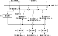
- FIG. 13 is a diagram showing an example of estimation of an estimated value VL.
- FIG. 13 is a diagram showing another example of estimation of the estimated value VL.
- FIG. 13 is a diagram showing an example of candidates for operating conditions Cd.
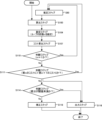
- FIG. 2 is a flowchart illustrating an example of a driving assistance method according to an embodiment of the present invention.
- 5 is a flowchart showing another example of a driving assistance method according to an embodiment of the present invention.
- 5 is a flowchart showing another example of a driving assistance method according to an embodiment of the present invention.
- 5 is a flowchart showing another example of a driving assistance method according to an embodiment of the present invention.
- 5 is a flowchart showing another example of a driving assistance method according to an embodiment of the present invention.
- FIG. 22 is a diagram showing an example of a computer 2200 in which the driving assistance device 100 according to an embodiment of the present invention may be embodied in whole or in part.
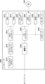
- FIG. 1 is a diagram showing an example of an electrolysis device 200 according to one embodiment of the present invention.
- the electrolysis device 200 of this example includes multiple electrolysis cells 90 (electrolysis cells 90-1 to 90-M, where M is an integer of 2 or more).
- the electrolysis cells 90 are cells that electrolyze an electrolyte.
- the electrolysis device 200 of this example includes an inlet pipe 92, an inlet pipe 93, an outlet pipe 94, and an outlet pipe 95.
- the inlet pipe 92 and the inlet pipe 93 are connected to each of the multiple electrolysis cells 90.
- the outlet pipe 94 and the outlet pipe 95 are connected to each of the multiple electrolysis cells 90.
- the electrolysis device 200 is a device that electrolyzes an electrolytic solution.
- the electrolytic cell 90 is a cell that electrolyzes an electrolytic solution.
- the electrolytic solution is, for example, an aqueous NaCl (sodium chloride) solution.
- the case where the electrolytic solution is an aqueous NaCl (sodium chloride) solution is referred to as saline electrolysis.
- the electrolytic cell 90 electrolyzes an aqueous NaCl (sodium chloride) solution in an anode chamber 79 (described later) to generate Cl 2 (chlorine), and electrolyzes H 2 O (water) in a cathode chamber 98 (described later) to generate NaOH (sodium hydroxide) and H 2 (hydrogen).
- the electrolyte electrolyzed in the electrolytic cell 90 may be an aqueous NaOH (sodium hydroxide) solution or an aqueous KOH (potassium hydroxide) solution.
- the electrolyte being an aqueous NaOH (sodium hydroxide) solution or an aqueous KOH (potassium hydroxide) solution is referred to as alkaline water electrolysis.
- the electrolytic cell 90 generates O 2 (oxygen) and H 2 (hydrogen) by electrolyzing an aqueous NaOH (sodium hydroxide) solution or an aqueous KOH (potassium hydroxide) solution.
- a first aqueous solution 70 is introduced into each of the multiple electrolytic cells 90.
- the first aqueous solution 70 may be introduced into each of the multiple electrolytic cells 90 after passing through an inlet pipe 92.
- the first aqueous solution 70 is an aqueous solution of an alkali metal chloride.
- An alkali metal is an element belonging to Group 1 of the periodic table.
- the first aqueous solution 70 may be an aqueous solution of NaCl (sodium chloride) or KCl (potassium chloride).
- the first aqueous solution 70 is an aqueous solution of NaCl (sodium chloride).
- the first aqueous solution 70 is an aqueous solution of NaOH (sodium hydroxide) or KOH (potassium hydroxide).
- a second aqueous solution 72 is introduced into each of the multiple electrolytic cells 90.
- the second aqueous solution 72 may be introduced into each of the multiple electrolytic cells 90 after passing through an introduction pipe 93.
- the second aqueous solution 72 is an aqueous solution of an alkali metal hydroxide.
- the second aqueous solution 72 is an aqueous solution of NaOH (sodium hydroxide) or KOH (potassium hydroxide).
- the second aqueous solution 72 is an aqueous solution of NaOH (sodium hydroxide) or KOH (potassium hydroxide).
- a third aqueous solution 74 and a gas 77 are discharged from each of the multiple electrolytic cells 90.
- the third aqueous solution 74 and the gas 77 may be discharged to the outside of the electrolysis device 200 after passing through the discharge pipe 94.
- the third aqueous solution 74 is an aqueous solution of an alkali metal chloride.
- the first aqueous solution 70 is an aqueous solution of NaCl (sodium chloride)
- the third aqueous solution 74 is an aqueous solution of NaCl (sodium chloride).
- the third aqueous solution 74 is an aqueous solution of KCl (potassium chloride).
- the gas 77 (described later) is Cl 2 (chlorine).
- the first aqueous solution 70 is an aqueous solution of NaOH (sodium hydroxide) or a KOH (potassium hydroxide).
- the third aqueous solution 74 is a NaOH (sodium hydroxide) aqueous solution.
- the first aqueous solution 70 is a NaOH (sodium hydroxide) aqueous solution
- the third aqueous solution 74 is a KOH (potassium hydroxide) aqueous solution.
- a fourth aqueous solution 76 and a gas 78 are discharged from each of the multiple electrolytic cells 90.
- the fourth aqueous solution 76 and the gas 78 may be discharged to the outside of the electrolysis device 200 after passing through a discharge pipe 95.
- the fourth aqueous solution 76 is an aqueous solution of an alkali metal hydroxide.
- the second aqueous solution 72 is an aqueous solution of NaOH (sodium hydroxide)
- the fourth aqueous solution 76 is an aqueous solution of NaOH (sodium hydroxide).
- the fourth aqueous solution 76 is an aqueous solution of KOH (potassium hydroxide).
- the gas 78 (described later) is H 2 (hydrogen).
- FIG. 2 is a diagram showing an example of one electrolytic cell 90 in FIG. 1.
- the electrolytic cell 90 may include multiple electrolytic cells 91 (electrolytic cell 91-1 to electrolytic cell 91-N, where N is an integer of 2 or more). N is, for example, 50.
- each of the electrolytic cells 90-1 to 90-M includes multiple electrolytic cells 91.
- the inlet pipe 92 and the inlet pipe 93 are connected to each of the electrolytic cells 91-1 to 91-N.
- a first aqueous solution 70 is introduced into each of the electrolytic cells 91-1 to 91-N.
- the first aqueous solution 70 may be introduced into each of the electrolytic cells 91-1 to 91-N after passing through the inlet pipe 92.
- a second aqueous solution 72 is introduced into each of the electrolytic cells 91-1 to 91-N.
- the second aqueous solution 72 may be introduced into each of the electrolytic cells 91-1 to 91-N after passing through the inlet pipe 93.
- the discharge pipe 94 and the discharge pipe 95 are connected to each of the electrolytic cells 91-1 to 91-N.
- a third aqueous solution 74 and a gas 77 (described later) are discharged from each of the electrolytic cells 91-1 to 91-N.
- the third aqueous solution 74 and the gas 77 (described later) may be discharged to the outside of the electrolytic device 200 after passing through the discharge pipe 94 from each of the electrolytic cells 91-1 to 91-N.
- a fourth aqueous solution 76 and a gas 78 are discharged from each of the electrolytic cells 91-1 to 91-N.
- the fourth aqueous solution 76 and the gas 78 (described later) may be discharged to the outside of the electrolytic device 200 after passing through the discharge pipe 95 from each of the electrolytic cells 91-1 to 91-N.
- FIG 3 is a diagram showing an example of the details of one electrolytic cell 91 in Figure 2.
- the electrolytic cell 90 has an anode chamber 79, an anode 80, a cathode chamber 98, a cathode 82, and ion exchange membranes 84 and 85.
- one electrolytic cell 91 has an anode chamber 79, an anode 80, a cathode chamber 98, a cathode 82, an ion exchange membrane 84, and a gasket 85.
- the anode chamber 79 and the cathode chamber 98 are provided inside the electrolytic cell 91.
- the anode chamber 79 and the cathode chamber 98 are separated by an ion exchange membrane 84.
- the anode 80 is disposed in the anode chamber 79.
- the cathode 82 is disposed in the cathode chamber 98.
- the gasket 85 holds the ion exchange membrane 84. By holding the ion exchange membrane 84, the gasket 85 prevents the liquid 73 and the liquid 75 from leaking outside the electrolytic cell 91.
- gasket 85-1 and gasket 85-2 sandwich the ion exchange membrane 84.
- the electrolytic cell 90 may have at least one of a temperature sensor 96 and a temperature sensor 97.
- the temperature sensor 96 measures a temperature T1 of the liquid 73 (described below).
- the temperature sensor 97 measures a temperature T2 of the liquid 75 (described below). At least one of the temperature T1 measured by the temperature sensor 96 and the temperature T2 measured by the temperature sensor 97 may be transmitted to the control unit 60 (described below).
- An inlet pipe 92 and an outlet pipe 94 are connected to the anode chamber 79.
- An inlet pipe 93 and an outlet pipe 95 are connected to the cathode chamber 98.
- the inlet pipe 92 and the inlet pipe 93 are connected to the bottom surface 87, and the outlet pipe 94 and the outlet pipe 95 are connected to the ceiling surface 88.
- the first aqueous solution 70 is introduced into the anode chamber 79.
- the second aqueous solution 72 is introduced into the cathode chamber 98.
- the third aqueous solution 74 is drawn out from the anode chamber 79.
- the fourth aqueous solution 76 is drawn out from the cathode chamber 98.
- the ion exchange membrane 84 is a membranous substance that blocks the passage of ions of the same sign as the ions arranged in the ion exchange membrane 84, and allows the passage of ions of the opposite sign.
- the ion exchange membrane 84 is a membrane that allows Na + (sodium ions) to pass through, and blocks the passage of OH - (hydroxide ions) and Cl - (chloride ions).
- the anode 80 and the cathode 82 may be maintained at a predetermined positive potential and a predetermined negative potential, respectively.
- the first aqueous solution 70 introduced into the anode chamber 79 and the second aqueous solution 72 introduced into the cathode chamber 98 are electrolyzed by the potential difference between the anode 80 and the cathode 82.
- the following chemical reaction occurs at the anode 80: [Chemical formula 1-1] (Chlorine electrolysis) 2Cl - ⁇ Cl 2 +2e - [Chemical formula 1-2] (alkaline water electrolysis) 4OH - ⁇ O 2 +2H 2 O+4e -
- the first aqueous solution 70 is an aqueous solution of NaCl (sodium chloride)
- NaCl (sodium chloride) is ionized into Na + (sodium ion) and Cl ⁇ (chloride ion) in the first aqueous solution 70.
- Cl 2 (chlorine) gas is generated by the chemical reaction shown in Chemical Formula 1-1.
- the gas 77 (the Cl 2 (chlorine) gas) and the third aqueous solution 74 may be led out from the anode chamber 79.
- the Na + (sodium ion) moves from the anode chamber 79 to the cathode chamber 98 via the ion exchange membrane 84 due to the attractive force from the cathode 82.
- the first aqueous solution 70 is an aqueous solution of NaOH (sodium hydroxide)
- NaOH sodium hydroxide
- NaOH sodium hydroxide
- OH ⁇ hydrooxide ion
- the gas 77 the O 2 (oxygen) gas
- the third aqueous solution 74 the H 2 O (water)
- the Na + (sodium ion) moves from the anode chamber 79 to the cathode chamber 98 via the ion exchange membrane 84 due to the attractive force from the cathode 82.
- a liquid 73 may be retained in the anode chamber 79.
- the liquid 73 may be an aqueous solution of an alkali metal chloride.
- the liquid 73 is an aqueous solution of NaCl (sodium chloride) or KCl (potassium chloride).
- the Na + (sodium ion) concentration and the Cl ⁇ (chloride ion) concentration of the liquid 73 may be smaller than the Na + (sodium ion) concentration and the Cl ⁇ (chloride ion) concentration of the first aqueous solution 70.
- the liquid 73 is an aqueous solution of KCl (potassium chloride)
- the K + (potassium ion) concentration and the Cl ⁇ (chloride ion) concentration of the liquid 73 may be smaller than the K + (potassium ion) concentration and the Cl ⁇ (chloride ion) concentration of the first aqueous solution 70.
- the liquid 73 is an aqueous solution of NaOH (sodium hydroxide) or KOH (potassium hydroxide).
- the second aqueous solution 72 is an aqueous solution of NaOH (sodium hydroxide)
- NaOH sodium hydroxide
- NaOH sodium hydroxide
- OH ⁇ hydrooxide ion
- the gas 78 the H 2 (hydrogen) gas
- the fourth aqueous solution 76 may be led out from the cathode chamber 98.
- the second aqueous solution 72 is an aqueous solution of KOH (potassium hydroxide).
- a liquid 75 may be retained in the cathode chamber 98.
- the liquid 75 may be an aqueous solution of an alkali metal hydroxide.
- the liquid 75 is an aqueous solution of NaOH (sodium hydroxide) or KOH (potassium hydroxide).
- the liquid 75 retained in the cathode chamber 98 contains dissolved OH - (hydroxide ions) produced by the chemical reaction shown in Chemical Formula 2 and Na + (sodium ions) transferred from the anode chamber 79.
- FIG. 4 is a view of the ion exchange membrane 84 in FIG. 3 viewed in the Y-axis direction.
- the gasket 85 in this example is a frame-shaped member that holds the edge of the ion exchange membrane 84 in the XZ plane. In FIG. 4, the gasket 85 is shown hatched. When viewed in the Y-axis direction, the gasket 85 may be arranged to surround the ion exchange membrane 84.
- the lower end 61 of the gasket 85 may be connected to the bottom surface 87 (see FIG. 3), and the upper end 62 may be connected to the ceiling surface 88 (see FIG. 3).
- One end 63 of the gasket 85 in the X-axis direction may be connected to one inner surface of the electrolysis cell 91 (see FIG.
- the other end 64 of the gasket 85 in the X-axis direction may be connected to the other inner surface of the electrolysis cell 91 (see FIG. 3) that intersects with the X-axis direction.
- FIG. 5 is an enlarged view of the vicinity of the ion exchange membrane 84 in the electrolysis cell 91 shown in FIG. 3.
- the gasket 85 in FIG. 4 is omitted.
- anion groups 86 are fixed to the ion exchange membrane 84.
- Anions are repelled by the anion groups 86 and therefore do not easily pass through the ion exchange membrane 84.
- the anions are OH ⁇ (hydroxide ions) and Cl ⁇ (chloride ions).
- Cations 71 are not repelled by the anion groups 86 and therefore can pass through the ion exchange membrane 84.
- the first aqueous solution 70 see FIG. 3 is an aqueous solution of NaCl (sodium chloride)
- the cations 71 are Na + (sodium ions).
- FIG. 6 is a block diagram of a driving assistance device 100 according to one embodiment of the present invention, and a diagram showing an example of a driving assistance system 300.
- the driving assistance device 100 assists in the operation of an electrolytic cell 90 (see FIG. 2).
- the driving assistance device 100 includes a calculation unit 10.
- the driving assistance device 100 may include an estimation unit 20, a selection unit 22, an input unit 30, an output unit 32, a memory unit 40, a current supply unit 50, and a control unit 60.
- the input unit 30 is, for example, a keyboard, a mouse, etc.
- the output unit 32 is, for example, a display, a monitor, etc.
- the driving assistance system 300 includes a driving assistance device 100 and an electrolytic bath 90.
- the control unit 60 may transmit a control signal Sc to the electrolytic bath 90 to control the electrolytic bath 90.
- the control unit 60 may transmit the control signal Sc wirelessly.
- the electrolytic bath 90 may transmit a control signal Sc' to the control unit 60.
- the electrolytic bath 90 may transmit the control signal Sc' wirelessly.
- the control signal Sc' may include at least one of a temperature T1 (described below) of the liquid 73 and a temperature T2 (described below) of the liquid 75.
- T1 temperature
- T2 temperature
- a part or the whole of the driving assistance device 100 is, for example, a computer equipped with a CPU, memory, an interface, etc.
- the control unit 60 may be the CPU.
- the calculation unit 10, the estimation unit 20, and the control unit 60 may be one CPU.
- a driving assistance program for causing the computer to function as the driving assistance device 100 or the driving assistance system 300 may be installed in the computer, and a driving assistance program for causing the computer to execute the driving assistance method described below may be installed in the computer.
- the estimated value of the performance change of the electrolytic performance in the electrolytic cell 90 is taken as the estimated value VL.
- the performance change of the electrolytic performance in the electrolytic cell 90 may be a performance change of the ion exchange membrane 84, the anode 80, the cathode 82, or the gasket 85 that the electrolytic cell 90 has.
- the estimated value VL may be an estimated value of a decrease in performance, or an estimated value of an increase in performance.
- the calculation unit 10 calculates the operating conditions of the electrolytic cell 90 (see FIG. 2) based on a first estimated value of the performance change of the electrolytic performance in the electrolytic cell 90.
- the first estimated value is referred to as the first estimated value VL1.
- the operating conditions are referred to as the operating conditions Cd.
- the operating conditions Cd refer to the operating conditions of the electrolytic cell 90 that may affect the state of the ion exchange membrane 84, the anode 80, the cathode 82, or the gasket 85.
- the first estimated value VL1 is an estimated value of the performance change of the ion exchange membrane 84, the anode 80, the cathode 82, or the gasket 85 after the calculation unit 10 calculates the operating conditions Cd. This allows the calculation unit 10 to calculate the operating conditions Cd that take into account the performance change of the ion exchange membrane 84, the anode 80, the cathode 82, or the gasket 85.
- the electrolytic bath 90 electrolyzes the first aqueous solution 70. Therefore, as the operating time of the electrolytic bath 90 progresses, one or more impurities may accumulate in the ion exchange membrane 84.
- the impurities accumulated in the ion exchange membrane 84 are referred to as impurities Im.
- the impurities Im may be compounds or elements.
- the term "one or more impurities Im" may refer to one or more types of impurities Im.
- the change in electrolysis performance may refer to a change in the performance of the ion exchange membrane 84 or a change in the performance of the gasket 85.
- the change in the performance of the ion exchange membrane 84 may refer to a change in performance due to accumulation of impurities Im in the ion exchange membrane 84 or the occurrence of perforations in the ion exchange membrane 84.
- the change in the performance of the gasket 85 may refer to a change in performance due to corrosion of the gasket 85.
- the liquid 73 may seep into the gap between the gasket 85-1 and the ion exchange membrane 84 in the Y-axis direction, or the liquid 75 may seep into the gap between the gasket 85-2 and the ion exchange membrane 84 in the Y-axis direction. This may cause the liquid 73 or the liquid 75 to penetrate into the gasket 85. This may cause the gasket 85 to corrode.
- the change in electrolysis performance in the electrolytic cell 90 may include a decrease and an increase in the electrolysis performance.
- the decrease and increase in the electrolysis performance may refer to a decrease and an increase in the performance of the ion exchange membrane 84 or the gasket 85.
- impurities Im accumulate in the ion exchange membrane 84
- the performance of the ion exchange membrane 84 is likely to decrease.
- the operating conditions Cd of the electrolytic cell 90 change, at least a portion of the impurities Im accumulated in the ion exchange membrane 84 may be removed. In such a case, the performance of the ion exchange membrane 84 may increase.
- the performance of the gasket 85 is likely to decrease.
- the liquid 73 that has seeped between the gasket 85-1 and the ion exchange membrane 84 in the Y-axis direction, or the liquid 75 that has seeped between the gasket 85-2 and the ion exchange membrane 84 in the Y-axis direction may be removed.
- the temperature T1 of the liquid 73 (see FIG. 3) or the temperature T2 of the liquid 75 (see FIG. 3) increases, the gasket 85 may expand.
- the elastic deformation amount (described later) of the gasket 85 may increase.
- the liquid 73 or liquid 73 that has seeped in may be removed as described above. In such a case, the performance of the gasket 85 may improve.
- the base material of the cathode 82 and the anode 80 may be Ni (nickel).
- the surface of the cathode 82 and the surface of the anode 80 may be coated with a metal coating agent.
- the metal may be, for example, Pt (platinum) or Ru (ruthenium).
- the coating agent may be formed by plating.
- the Pt (platinum) or Ru (ruthenium) provided on the surface of the cathode 82 may be contained in the liquid 75 (see FIG. 3).
- the impurities Im may include Ni (nickel), Pt (platinum) or Ru (ruthenium).
- the estimation unit 20 may estimate the first estimated value VL1 based on an actual value of impurity data relating to the accumulation rate of impurities Im in the ion exchange membrane 84.
- the impurity data is defined as impurity data Di.
- the actual value of the impurity data Di is defined as actual value Vi.
- the actual value Vi of the impurity data Di may include an actual value of the accumulation rate or an actual value of the accumulation amount of one or more elements constituting the one or more impurities Im accumulating in the ion exchange membrane 84.
- the actual value of the accumulation rate or the actual value of the accumulation amount of the one or more elements is defined as actual value Vi'.
- the estimation unit 20 may estimate one or more impurities Im based on the actual value Vi'.
- the estimation unit 20 may estimate one or more types of impurities Im based on the actual value Vi'. If the impurity Im is a compound, the type of impurity Im refers to the type of compound. If the impurity Im is an element, the type of impurity Im refers to the type of element.
- the estimation unit 20 may estimate a first estimated value VL1 based on the estimated accumulation rate or accumulation amount of one or more impurities Im. The estimation unit 20 may estimate a first estimated value VL1 based on the estimated accumulation rate or accumulation amount of one or more types of impurities Im.
- the actual value Vi and the actual value Vi' may be actual analysis data of the ion exchange membrane 84.
- the actual analysis data refers to data evaluated by actual analysis of the ion exchange membrane 84.
- the impurity Im is a compound
- the actual value Vi' may be actual analysis data of multiple elements constituting the compound accumulated in the ion exchange membrane 84, and the accumulation amount or accumulation rate of each of the elements.
- the actual analysis data may be obtained by actual analysis of the ion exchange membrane 84 removed from the electrolytic cell 90 while the operation of the electrolytic cell 90 is stopped.
- the actual analysis data may be obtained by actual analysis of the elements contained in the liquid 73 or liquid 75 leaking from the electrolytic cell 91 while the electrolytic cell 90 is operating.
- the estimation unit 20 may estimate one or more compounds based on the accumulation amount or accumulation rate of each element that has been actually analyzed.
- One or more compounds may refer to one or more types of compounds.
- the estimation unit 20 may estimate the type of one or more compounds based on the accumulation amount or accumulation rate of each element that has been actually analyzed.
- the actual value Vi' may be analysis data for each element of the accumulation amount or accumulation rate of one or more elements accumulated in the ion exchange membrane 84.
- the estimation unit 20 may estimate one or more elements based on the accumulation amount or accumulation rate of each element that is actually analyzed.
- One or more elements refers to one or more types of elements.
- the accumulation amount of one or more elements constituting the impurity Im may be the accumulation amount over a predetermined fixed period Te.
- the fixed period Te is, for example, one year.
- the accumulation rate of one or more elements constituting the impurity Im may be the accumulation amount per predetermined fixed period Te'.
- the fixed period Te' may be equal to the fixed period Te or may be different.
- the estimation unit 20 may calculate the accumulation rate or amount of impurities Im for one or more estimated impurities Im.
- the accumulation amount of impurities Im may be the accumulation amount of impurities Im over a certain period Te'.
- the accumulation rate of impurities Im may be the accumulation amount of impurities Im per certain period Te'.
- the estimation unit 20 may calculate the accumulation rate or amount of impurities Im for each impurity Im.
- the actual value Vi may be evaluated when the ion exchange membrane 84 is removed from the electrolytic cell 90, or when it is attached to the electrolytic cell 90.
- the actual value Vi' may be data obtained by analyzing the relationship between the accumulation amount or accumulation rate of each of the multiple elements that make up the impurities Im and the operating time of the electrolytic cell 90 when the ion exchange membrane 84 or the gasket 85 is attached to the electrolytic cell 90.
- the estimation unit 20 may estimate the first estimated value VL1 based on the actual value of the elastic deformation amount of the gasket 85.
- the elastic deformation amount of the gasket 85 refers to the amount of deformation of the gasket 85-1 or the gasket 85-2 due to the application of this pressing force.
- the amount of elastic deformation of the gasket 85 may change.
- the amount of elastic deformation of the gasket 85 may be the difference between the thickness of the gasket 85 in the Y-axis direction before corrosion and the thickness of the gasket 85 in the Y-axis direction after corrosion.
- the thickness of the gasket 85 in the Y-axis direction may be the average value or the median value of the thickness of the gasket 85 in the Y-axis direction around the periphery of the ion exchange membrane 84 in Figure 4.
- the actual value of the elastic deformation amount of the gasket 85 is taken as the actual value Vj.
- the actual value Vj may be actual analysis data of the elastic deformation amount.
- the actual analysis data may be obtained by actually analyzing the gasket 85 removed from the electrolytic cell 90 while the operation of the electrolytic cell 90 is stopped.
- the actual analysis data may be obtained by actually analyzing the elements contained in the liquid 73 or liquid 75 leaking from the electrolytic cell 91 while the electrolytic cell 90 is operating.
- the actual values Vi and Vj may be input by the input unit 30.
- the actual values Vi and Vj input by the input unit 30 may be stored in the storage unit 40.
- the alkali metal chloride contained in the liquid 73 may pass through the ion exchange membrane 84.
- the alkali metal chloride that passes through the ion exchange membrane 84 may be included in the liquid 75.
- the liquid 75 is an aqueous solution of an alkali metal hydroxide.
- the impurity data Di may include concentration data of the impurity Im in the liquid 73.
- the actual value Vi may be actual analysis data obtained by actually analyzing the concentration of the impurity Im in the aqueous solution of NaCl (sodium chloride).
- the first estimated value VL1 is, for example, the rate of decrease in the current efficiency CE of the electrolytic cell 90.
- the current efficiency CE refers to the ratio of the actual production volume to the theoretical production volume of the product produced by the electrolytic cell 90.
- the product in question is product P.
- the theoretical production volume of product P is production volume Pa.
- the actual production volume of product P is production volume Pr.
- the current efficiency CE refers to the ratio of production volume Pr to production volume Pa.
- the first estimated value VL1 may be the rate of increase in the voltage CV of the electrolytic cell 90. The greater the amount of impurities Im accumulated in the ion exchange membrane 84, the more likely the voltage CV is to increase.
- FIG. 7 is a diagram showing an example of the relationship between the accumulation amount of impurity Im and current efficiency CE for each impurity Im.
- the relationship between the accumulation amount of impurity Im and current efficiency CE is shown for each of four impurities Im (impurity Im1 to impurity Im4).
- the types of impurities Im1 to impurity Im4 are different from each other.
- Impurity Im1 is, for example, a compound of Ba (barium) and I (iodine).
- Impurity Im2 is, for example, a compound of Ca (calcium), Sr (strontium), and I (iodine).
- Impurity Im3 is, for example, I (iodine).
- Impurity Im4 is, for example, a compound of Si (silicon) and Al (aluminum).
- the current efficiency CE is more likely to decrease as the amount of accumulated impurities Im increases.
- the amount of decrease in current efficiency CE per amount of accumulated impurities Im may differ depending on the type of impurities Im.
- the relationship between the amount of accumulated impurities Im and current efficiency CE shown in FIG. 7 may be stored in the memory unit 40 (see FIG. 6).
- the estimation unit 20 may estimate the first estimated value VL1 based on the accumulation rate or amount of impurities Im in the ion exchange membrane 84.
- the estimation unit 20 may estimate the first estimated value VL1 based on the accumulation rate or amount of a plurality of impurities Im.
- the performance degradation rate of the ion exchange membrane 84 for each impurity Im is set as the first estimated value VL1'.
- the first estimated value VL1' is the degradation rate of the current efficiency CE.
- the first estimated values VL1' of the performance change of the ion exchange membrane 84 for each impurity Im1 to impurity Im4 are set as the first estimated value VL1'-1 to the first estimated value VL1'-4, respectively.
- the estimation unit 20 may estimate a first estimated value VL1 of the performance change of the ion exchange membrane 84 in which a plurality of impurities Im have accumulated, based on the relationship between the accumulation rate or accumulation amount of the impurities Im for each impurity Im and the first estimated value VL1'.
- the relationship between the accumulation rate or accumulation amount of the impurities Im and the first estimated value VL1' may be the actual relationship between the accumulation rate or accumulation amount of the impurities Im and the first estimated value VL1'. In the example of FIG.
- the estimation unit 20 estimates the first estimated value VL1 based on the relationship between the accumulation amount of impurity Im1 and the first estimated value VL1'-1, the relationship between the accumulation amount of impurity Im2 and the first estimated value VL1'-2, the relationship between the accumulation amount of impurity Im3 and the first estimated value VL1'-3, and the relationship between the accumulation amount of impurity Im4 and the first estimated value VL1'-4.
- the estimation unit 20 may estimate the first estimated value VL1 based on the concentration data of the impurity Im in the liquid 73.
- the estimation unit 20 may estimate one or more impurities Im based on the concentration data of the impurity Im, and estimate the first estimated value VL1 based on the accumulation rate or accumulation amount of the estimated one or more impurities Im.
- the estimation unit 20 may estimate one or more impurities Im based on the actual value Vi', and estimate the first estimated value VL1 based on the estimated accumulation rate or accumulation amount of the one or more impurities Im and the concentration data of the impurity Im in the liquid 73.
- the estimation unit 20 may estimate the first estimated value VL1 based on the actual value of the elastic deformation amount of the gasket 85. In the example of FIG. 8, the estimation unit 20 estimates the rate of decrease of the current efficiency CE as the first estimated value VL1.
- FIG. 9 shows an example of the relationship between the remaining amount of metal coating agent on the surface of the cathode 82 and the surface of the anode 80 and the voltage CV of the electrolytic cell 90 for each material of the coating agent.
- the material may be an element or a compound.
- the relationship between the remaining amount of coating agent and the voltage CV is shown for each of two materials (material A and material B).
- the types of material A and material B are different from each other.
- Material A is, for example, Ru (ruthenium).
- Material B is, for example, Pt (platinum).
- the change in electrolysis performance in the electrolytic cell 90 may be a change in performance based on the remaining amount of metal coating agent on the surface of the cathode 82 and the surface of the anode 80. If the remaining amount of coating agent on the cathode 82 changes, the performance of the cathode 82 may change. If the remaining amount of coating agent on the anode 80 changes, the performance of the anode 80 may change. If the performance of the cathode 82 or the anode 80 changes, the electrolysis performance of the electrolytic cell 90 may change. If the remaining amount of coating agent decreases, the voltage CV is likely to increase as shown in FIG. 9. This makes it easy for the electrolysis performance of the electrolytic cell 90 to decrease. As shown in FIG. 9, the amount of increase in voltage CV per remaining amount may differ depending on the type of material. The relationship between the remaining amount and voltage CV shown in FIG. 9 may be stored in the memory unit 40 (see FIG. 6).
- the estimation unit 20 may estimate the first estimated value VL1 based on the remaining amount of metal coating agent on the surface of the cathode 82 and the surface of the anode 80.
- the remaining amount of coating agent may be obtained by actually analyzing the cathode 82 or anode 80 removed from the electrolytic cell 90 while the operation of the electrolytic cell 90 is stopped.
- the remaining amount of coating agent may be obtained by changing the magnitude of the current supplied to the electrolytic cell 90 while the electrolytic cell 90 is operating, and analyzing the change in electrolytic performance corresponding to the change in the magnitude of the current.
- the estimation unit 20 may estimate the first estimated value VL1 based on the relationship between the remaining amount of metal coating agent on the surface of the cathode 82 and the surface of the anode 80 and the voltage CV.
- the rate of increase in the voltage CV for each material is the first estimated value VL1''.
- the first estimated values VL1'' for materials A to D are first estimated value VL1''-1 to first estimated value VL1''-4, respectively.
- the estimation unit 20 may estimate the first estimated value VL1 of the performance change based on the relationship between the remaining amount of coating agent and the first estimated value VL1'' for each material.
- the relationship between the remaining amount and the first estimated value VL1'' may be the actual relationship between the remaining amount and the first estimated value VL1''.
- the estimation unit 20 estimates the first estimated value VL1 based on the relationship between the remaining amount of material A and the first estimated value VL1''-1, the relationship between the remaining amount of material B and the first estimated value VL1'-2, the relationship between the remaining amount of material C and the first estimated value VL1'-3, and the relationship between the remaining amount of material D and the first estimated value VL1'-4.
- the estimation unit 20 may estimate the remaining amount of the metal coating agent based on actual values of the type and amount of elements contained in the coating agent on the surface of the cathode 82 and the surface of the anode 80.
- the actual values of the type and amount of elements contained in the coating agent may be obtained by an X-ray fluorescence analysis terminal.
- First actual values of the type and amount of elements contained in the coating agent before the cathode 82 and the anode 80 begin to be used may be obtained by the X-ray fluorescence analysis terminal.
- the estimation unit 20 may estimate a second actual value of the type and amount of an element contained in the coating agent after the cathode 82 and the anode 80 start to be used (i.e., after the electrolytic cell 90 starts to operate) based on the first actual value, a first result of the X-ray fluorescence analysis before the cathode 82 and the anode 80 start to be used, and a second result of the X-ray fluorescence analysis after the cathode 82 and the anode 80 start to be used.
- the estimation unit 20 estimates a second actual value of the amount of an element (e.g., Ru (ruthenium)) contained in the coating agent by multiplying the first actual value by the ratio of the peak intensity of the second result to the peak intensity of the first result of the element. For example, the estimation unit 20 estimates a second remaining amount of the coating agent after the cathode 82 and the anode 80 start to be used by multiplying the first remaining amount of the coating agent before the cathode 82 and the anode 80 start to be used by the ratio of the second actual value to the first actual value.
- Ru ruthenium
- the estimation unit 20 may estimate the first estimated value VL1 based on the update period of the ion exchange membrane 84, the gasket 85, or the cathode 82 or the anode 80, at least one of the concentrations D0 (described later) and D1 (described later), and the actual value Vi.
- the update period of the ion exchange membrane 84 is defined as the update period Tu.
- the ion exchange membrane 84 may be renewed. Renewal of the ion exchange membrane 84 refers to removing impurities Im that are causing the performance deterioration of the ion exchange membrane 84, or replacing the ion exchange membrane 84 whose performance has deteriorated with a new ion exchange membrane 84.
- the renewal period Tu refers to the period for renewing the ion exchange membrane 84.
- the gasket 85 may be renewed. Renewal of the gasket 85 refers to removing impurities Im that are causing the performance deterioration of the gasket 85, or replacing the gasket 85 whose performance has deteriorated with a new gasket 85.
- the renewal period Tu may refer to the period for renewing the gasket 85.
- the cathode 82 may be renewed. Renewal of the cathode 82 refers to replacing the cathode 82 with a reduced amount of coating with a new cathode 82.
- the renewal period Tu may refer to the period for renewing the cathode 82. The same applies to the anode 80.
- the estimation unit 20 may estimate the first estimated value VL1 based on the actual value Vi and a predetermined constraint condition.
- the constraint condition is referred to as the constraint condition Cr1.
- the constraint condition Cr1 includes, for example, at least one of the range of concentration D0 (described later) and the range of flow rate F0 (described later) of the second aqueous solution 72 flowing through the inlet pipe 93, at least one of the range of concentration D1 (described later) and the range of flow rate F1 (described later) of the fourth aqueous solution 76 flowing through the outlet pipe 95, the range of concentration D1-1 to concentration D1-m (described later) or the range of concentration D1-1' to concentration D1-m' (described later) of the fourth aqueous solution 76 flowing through the outlet pipe 95, and the range of flow rate F0-1 to flow rate F0-m (described later) or the range of flow rate F0-1' to flow rate F0-m' (described later) of the second aque
- the first estimated value VL1 may be estimated without being based on the actual value Vi or the actual value Vi'.
- the first estimated value VL1 may be estimated based on a decrease in the current efficiency CE of the electrolytic cell 90, or may be estimated based on an increase in the voltage CV of the electrolytic cell 90.
- the current efficiency CE is likely to decrease and the voltage CV is likely to increase.
- the operating conditions Cd may have a number of parameters related to the operation of the electrolytic cell 90.
- the parameters are referred to as parameters Pr.
- the parameters Pr may include the current I supplied to the electrolytic cell 90, the salt concentration of the first aqueous solution 70, the alkali concentration of the second aqueous solution 72, the salt concentration of the third aqueous solution 74, the alkali concentration of the fourth aqueous solution 76, the flow rate of the first aqueous solution 70, the flow rate of the second aqueous solution 72, the flow rate of the third aqueous solution 74, the flow rate of the fourth aqueous solution 76, the temperature T1 of the aqueous solution of alkali metal chloride in the anode chamber 79, and the temperature T2 of the aqueous solution of alkali metal hydroxide in the cathode chamber 98.
- the aqueous solution of alkali metal chloride in the anode chamber 79 refers to the liquid 73 (see FIG. 3).
- the aqueous solution of alkali metal hydroxide in the cathode chamber 98 refers to the liquid 75 (see FIG. 3).
- parameter Pr1 One of the multiple parameters Pr is designated as parameter Pr1, and the other parameters Pr excluding parameter Pr1 are designated as parameter Pr2.
- the setting value of parameter Pr is designated as setting value Vs. Setting value Vs may be set by the user of the driving assistance device 100.
- the calculation unit 10 may calculate the parameter Pr1 as the first operating condition Cd1 (described later) based on the first estimated value VL1. For example, the calculation unit 10 calculates the first current I1 as the first operating condition Cd1 based on the first estimated value VL1. The calculation unit 10 may calculate a first setting value of the parameter Pr2 based on the first estimated value VL1. The first setting value is set as the first setting value Vs1. The first setting value Vs1 is the value of the parameter Pr2 that should be realized in the electrolytic cell 90 after the calculation unit 10 calculates the operating condition Cd.
- the control unit 60 may transmit the first setting value Vs1 calculated by the calculation unit 10 to the electrolytic cell 90 as a control signal Sc.
- the calculation unit 10 may calculate the parameter Pr1 based on the calculated first set value Vs1.
- the parameter Pr1 may be the current I supplied to the electrolytic cell 90, or may be a parameter Pr other than the current I.
- Parameter Pr1 may be a first current I1 supplied to the electrolytic cell 90.
- the calculation unit 10 may calculate the first current I1 as a first operating condition Cd1 (described later) based on the first estimated value VL1.
- the calculation unit 10 may calculate the first current I1 as the parameter Pr1 based on the first set value Vs1.
- the current supply unit 50 (see FIG. 6) may supply the first current I1 to the electrolytic cell 90. This allows the electrolytic cell 90 to be controlled under the operating condition Cd based on the first estimated value VL1.
- Parameter Pr2 may be at least one of the multiple parameters Pr excluding parameter Pr1.
- parameter Pr2 may be at least one of the salt concentration of the first aqueous solution 70, the alkali concentration of the second aqueous solution 72, the salt concentration of the third aqueous solution 74, the alkali concentration of the fourth aqueous solution 76, the flow rate of the first aqueous solution 70, the flow rate of the second aqueous solution 72, the flow rate of the third aqueous solution 74, the flow rate of the fourth aqueous solution 76, the temperature T1 of the aqueous solution of alkali metal chloride in the anode chamber 79, and the temperature T2 of the aqueous solution of alkali metal hydroxide in the cathode chamber 98.
- the salt concentration of the first aqueous solution 70 refers to the concentration of alkali metal chloride in the first aqueous solution 70.
- the salt concentration of the first aqueous solution 70 may refer to the salt concentration of the first aqueous solution 70 at the inlet to the anode chamber 79.
- the alkali concentration of the second aqueous solution 72 refers to the concentration of alkali metal hydroxide in the second aqueous solution 72.
- the alkali concentration of the second aqueous solution 72 may refer to the alkali concentration of the second aqueous solution 72 at the inlet to the cathode chamber 98.
- the salt concentration of the third aqueous solution 74 refers to the concentration of alkali metal chloride in the third aqueous solution 74.
- the salt concentration of the third aqueous solution 74 may refer to the salt concentration of the third aqueous solution 74 at the outlet from the anode chamber 79.
- the alkali concentration of the fourth aqueous solution 76 refers to the concentration of alkali metal hydroxide in the fourth aqueous solution 76.
- the alkali concentration of the fourth aqueous solution 76 may refer to the alkali concentration of the fourth aqueous solution 76 at the outlet from the cathode chamber 98.
- the flow rate of the first aqueous solution 70 refers to the flow rate of the first aqueous solution 70 flowing through the inlet pipe 92.
- the flow rate of the first aqueous solution 70 may refer to the mass or volume of the first aqueous solution 70 flowing through the inlet pipe 92 per unit time.
- the flow rate of the second aqueous solution 72 refers to the flow rate of the second aqueous solution 72 flowing through the inlet pipe 93.
- the flow rate of the second aqueous solution 72 may refer to the mass or volume of the second aqueous solution 72 flowing through the inlet pipe 93 per unit time.
- the flow rate of the third aqueous solution 74 refers to the flow rate of the third aqueous solution 74 flowing through the outlet pipe 94.
- the flow rate of the third aqueous solution 74 may refer to the mass or volume of the third aqueous solution 74 flowing through the outlet pipe 94 per unit time.
- the flow rate of the fourth aqueous solution 76 refers to the flow rate of the fourth aqueous solution 76 flowing through the outlet pipe 95.
- the flow rate of the fourth aqueous solution 76 may refer to the mass or volume of the fourth aqueous solution 76 flowing through the outlet pipe 95 per unit time.
- the temperature T1 of the liquid 73 may be measured by a temperature sensor 96 (see FIG. 3).
- the temperature T2 of the liquid 75 may be measured by a temperature sensor 97 (see FIG. 3).
- FIG. 10 is a diagram showing an example of the first set value Vs1 of the parameter Pr2 when there are multiple electrolytic baths 90.
- the parameter Pr2 is the concentration and flow rate of the second aqueous solution 72 and the concentration and flow rate of the fourth aqueous solution 76.
- the electrolysis device 200 may include a downstream process storage section 112.
- the fourth aqueous solution 76 is stored in the downstream process storage section 112.
- the downstream process storage section 112 may store a product produced by the electrolytic cell 90. This product is referred to as product P.
- the product P is NaOH (sodium hydroxide, commonly known as caustic soda).
- the product P may include a portion of the second aqueous solution 72.
- the alkali concentration of the second aqueous solution 72 is concentration D0.
- the flow rate of the second aqueous solution 72 is flow rate F0.
- the concentrations D0 of the second aqueous solution 72 introduced into the electrolytic baths 90-1 to 90-M are concentration D0-1 to concentration D0-m, respectively.
- the flow rates F0 of the second aqueous solution 72 introduced into the electrolytic baths 90-1 to 90-M are flow rates F0-1 to F0-m, respectively.
- the concentrations D0, D0-1 to D0-m, flow rate F0, and flow rates F0-1 to F0-m are the first set value Vs1 of the parameter Pr2.
- concentrations D0-1 to D0-m are equal to each other, and flow rates F0-1 to F0-m are equal to each other.
- concentrations D0-1 to D0-m are each equal to concentration D0 of the second aqueous solution 72 flowing through the inlet pipe 93, and the sum of flow rates F0-1 to F0-m is equal to flow rate F0.
- the alkali concentration of the fourth aqueous solution 76 is concentration D1.
- the flow rate of the fourth aqueous solution 76 is flow rate F1.
- the concentrations D1 of the fourth aqueous solution 76 derived from the electrolytic cells 90-1 to 90-M are concentration D1-1 to concentration D1-m, respectively.
- the flow rates F1 of the fourth aqueous solution 76 derived from the electrolytic cells 90-1 to 90-M are flow rates F1-1 to F1-m, respectively.
- the concentrations D1, D1-1 to D1-m, flow rate F1, and flow rates F1-1 to F1-m are the first set value Vs1 of the parameter Pr2.
- concentrations D1-1 to D1-m are equal to each other, and flow rates F1-1 to F1-m are equal to each other.
- concentration D1 at the inlet of downstream storage section 112 is equal to each of concentrations D1-1 to D1-m.
- flow rate F1 at the inlet of downstream storage section 112 is m times each of flow rates F1-1 to F1-m, and is the sum of flow rates F1-1 to F1-m.
- Flow rates F0 and F1 may be equal. Flow rates F0-1 and F1-1 may be equal, flow rates F0-2 and F1-2 may be equal, and flow rates F0-m and F1-m may be equal.
- the calculation unit 10 may calculate the concentration D0, concentration D0-1 to concentration D0-m, flow rate F0, and flow rate F0-1 to flow rate F0-m as the first set value Vs1 of the parameter Pr2, and may calculate the concentration D1, concentration D1-1 to concentration D1-m, and flow rate F1 and flow rate F1-1 to flow rate F1-m.
- concentration D0, concentration D0-1 to concentration D0-m, flow rate F0, and flow rate F0-1 to flow rate F0-m, and the concentration D1, concentration D1-1 to concentration D1-m, flow rate F1, and flow rate F1-1 to flow rate F1-m may be the first set value Vs1 before the calculation unit 10 calculates the first set value Vs1 based on the first estimated value VL1.
- the total power consumption of the multiple electrolytic baths 90 in a predetermined period is defined as the power consumption Pw.
- the power consumption Pw is the sum of the power consumption of the electrolytic baths 90-1 to 90-M.
- the power consumption Pw is the power consumption of one electrolytic bath 90.
- the predetermined period may be a period based on a production plan for the product P produced by the multiple electrolytic baths 90.
- the predetermined period may be set by a user of the driving assistance device 100.
- the predetermined period is defined as a fixed period T.
- the total production amount of the product P produced by the multiple electrolytic baths 90 in the fixed period T is defined as the production amount Pa.
- the production amount Pa is the sum of the production amounts P of the electrolytic baths 90-1 to 90-M.
- the production amount Pa is the production amount P of one electrolytic bath 90.
- the predetermined amount of power Pw in a certain period T is defined as the amount of power Pwd.
- the amount of power Pwd may be the amount of power Pw desired by the user of the driving assistance device 100.
- the amount of power Pwd may be a value within a predetermined range of the amount of power Pw, or may be the minimum value of the amount of power Pw.
- the predetermined production amount Pa in a certain period T is defined as the production amount Pad.
- the production amount Pad may be a value within a predetermined range of the production amount Pa, or may be the maximum value of the production amount Pa.
- the calculation unit 10 may calculate a first current I1 for each of the multiple electrolytic baths 90 such that the power amount Pw in a certain period T becomes the power amount Pwd, or the production amount Pa in a certain period T becomes the production amount Pad.
- the first current I1 of the electrolytic bath 90-1, the first current I1 of the electrolytic bath 90-2, and the first current I1 of the electrolytic bath 90-M are equal.
- the current supply unit 50 (see FIG. 6) may supply the first current I1 calculated by the calculation unit 10 to each of the multiple electrolytic baths 90.
- the estimation unit 20 may estimate the first estimated value VL1 for each of the multiple electrolytic baths 90 based on the actual value Vi.
- the calculation unit 10 may calculate the first set value Vs1 of the parameter Pr2 for each of the multiple electrolytic baths 90, such that the power amount Pw in a certain period T becomes the power amount Pwd, or the production amount Pa in a certain period T becomes the production amount Pad, based on the first estimated value VL1 for each of the multiple electrolytic baths 90.
- the calculation unit 10 may calculate the first set value Vs1 for each of the multiple electrolytic baths 90, such that the production amount Pa in a certain period T becomes the production amount Pad and the power amount Pw becomes the power amount Pwd, based on the first estimated value VL1 for each of the multiple electrolytic baths 90.
- the calculation unit 10 calculates the concentration D0, concentrations D0-1 to D0-m, flow rate F0, and flow rate F0-1' to F0-m' as the first set value Vs1, and calculates the concentration D1, concentrations D1-1' to D1-m', flow rate F1, and flow rate F1-1' to F1-m'.
- the flow rate F0-1' is greater than the flow rate F0-1 (see FIG. 10)
- the flow rate F0-2' is less than the flow rate F0-2 (see FIG. 10)
- the flow rate F0-m' is less than the flow rate F0-m (see FIG. 10).
- the flow rate F0-1' is greater than each of the flow rates F0-2' through F0-m'.
- concentration D1-1' is smaller than concentration D1-1 (see FIG. 10)
- concentration D1-2' is larger than concentration D1-2 (see FIG. 10)
- concentration D1-m' is larger than concentration D1-m (see FIG. 10).
- concentration D1-1' is smaller than each of concentrations D1-2' to D1-m'.
- flow rate F1-1' is larger than flow rate F1-1 (see FIG. 10)
- flow rate F1-2' is smaller than flow rate F1-2 (see FIG. 10
- flow rate F1-m' is smaller than flow rate F1-m (see FIG. 10).
- flow rate F1-1' is larger than each of flow rates F1-2' to F1-m'.
- Flow rates F0-1' and F1-1' may be equal, flow rates F0-2' and F1-2' may be equal, and flow rates F0-m' and F1-m' may be equal.
- Concentration D0 and flow rate F0 in FIG. 11 may be equal to concentration D0 and flow rate F0 in FIG. 10, respectively.
- Concentration D1 and flow rate F1 at the inlet of downstream storage section 112 in FIG. 11 may be equal to concentration D1 and flow rate F1 at the inlet of downstream storage section 112 in FIG. 10, respectively.
- the calculation unit 10 may calculate the first current I1 for each of the multiple electrolytic baths 90 based on the first estimated value VL1 for each of the multiple electrolytic baths 90 and a predetermined constraint condition.
- the constraint condition is referred to as constraint condition Cr2.
- the calculation unit 10 may calculate the first current I1 for each of the multiple electrolytic baths 90 based on the first estimated value VL1 for each of the multiple electrolytic baths 90 so as to satisfy the constraint condition Cr2.
- the constraint condition Cr2 may include the power amount Pw or the production amount Pa in the fixed period T.
- the calculation unit 10 (see FIG. 6) may calculate the first current I1 such that the power amount Pw in the fixed period T becomes the power amount Pwd, or the production amount Pa in the fixed period T becomes the production amount Pad, based on the first estimated value VL1.
- the calculation unit 10 may calculate the first current I1 for each of the multiple electrolytic baths 90 such that the power amount Pw in the fixed period T becomes the power amount Pwd, or the production amount Pa in the fixed period T becomes the production amount Pad, based on the first estimated value VL1 for each of the multiple electrolytic baths 90.
- the calculation unit 10 may calculate the first current I1 for each of the multiple electrolytic baths 90 such that the production amount Pa in the fixed period T becomes the production amount Pad and the power amount Pw becomes the power amount Pwd, based on the first estimated value VL1 for each of the multiple electrolytic baths 90.
- the calculation unit 10 may calculate, for each of the multiple electrolytic baths 90, a first setting value Vs1 of the parameter Pr2 such that the power amount Pw in a certain period T becomes the power amount Pwd or the production amount Pa in a certain period T becomes the production amount Pad, based on the first estimated value VL1 for each of the multiple electrolytic baths 90, and calculate a first current I1 for each of the multiple electrolytic baths 90 based on the calculated first setting value Vs1 for each.
- the current supply unit 50 may supply the first current I1 calculated by the calculation unit 10 to each of the multiple electrolytic baths 90.
- the performance changes of the ion exchange membrane 84, the gasket 85, or the cathode 82 or the anode 80 may differ for each electrolytic cell 90.
- the calculation unit 10 calculates the first current I1 for each of the multiple electrolytic cells 90 based on the first estimated value VL1 for each of the multiple electrolytic cells 90, such that the amount of power Pw in a certain period T becomes the amount of power Pwd, or the production amount Pa in a certain period T becomes the production amount Pad.
- the calculation unit 10 can calculate the operating condition Cd for which the amount of power Pw in a certain period T becomes the amount of power Pwd, or the production amount Pa in a certain period T becomes the production amount Pad, while taking into account the first estimated value VL1 of the performance change for each electrolytic cell 90.
- the calculation unit 10 may calculate the first current I1 supplied to the electrolytic cell 90-1 in the example of FIG. 11 to be smaller than the first current I1 supplied to the electrolytic cell 90-1 in the example of FIG. 10.
- the calculation unit 10 may calculate the first current I1 supplied to the electrolytic cell 90-2 in the example of FIG. 11 to be larger than the first current I1 supplied to the electrolytic cell 90-2 in the example of FIG. 10, and may calculate the first current I1 supplied to the electrolytic cell 90-M in the example of FIG. 11 to be larger than the first current I1 supplied to the electrolytic cell 90-M in the example of FIG. 10.
- the calculation unit 10 may calculate the cost associated with the operation of one or more electrolytic cells 90. This cost is referred to as cost C.
- Cost C may include the electricity cost for operating the electrolysis device 200 (see FIGS. 1 and 2), the unpaid cost of the ion exchange membrane 84 or the gasket 85 when the ion exchange membrane 84 or the gasket 85 is replaced before the performance of the ion exchange membrane 84 or the gasket 85 is completely degraded, and the unpaid cost of the cathode 82 or the anode 80 when the cathode 82 or the anode 80 is replaced before the remaining amount of the coating agent of the cathode 82 or the anode 80 runs out.
- the electricity cost for operating the electrolysis device 200 may be calculated by multiplying the amount of power consumed in each electrolytic cell 90 by the electricity cost per unit of power consumption.
- the amount of power consumption may be calculated by multiplying the voltage CV of the electrolytic cell 90 by the current flowing through the electrolytic cell 90 and the operating time. If the electricity cost is the electricity cost per day, the operating time may be 24 hours.
- the electricity cost for operating the electrolysis device 200 may be the total electricity cost of the multiple electrolytic cells 90.
- Cost C may further include at least one of the maintenance cost of the electrolysis device 200 and the opportunity loss cost.
- Cost C may further include the purchase cost of new ion exchange membrane 84, gasket 85, cathode 82 or anode 80 when the ion exchange membrane 84, gasket 85, cathode 82 or anode 80 is renewed.
- the opportunity loss cost refers to the profit of the product P that would have been obtained if the electrolysis device 200 had continued to operate when a period during which the electrolysis device 200 cannot operate occurs.
- the predetermined cost C for a certain period T is defined as cost Cp.
- Cost Cp may be the cost C desired by the user of the driving assistance device 100.
- Cost Cp may be a value within a predetermined range of cost C, or may be the minimum value of cost C.
- the constraint condition Cr2 may include a cost C in a certain period T.
- the calculation unit 10 (see FIG. 6) may calculate a parameter Pr1 such that the cost C in the certain period T becomes the cost Cp based on the first estimated value VL1.
- the calculation unit 10 may calculate a parameter Pr1 such that the cost C in the certain period T becomes the cost Cp for each of the multiple electrolytic baths 90 based on the first estimated value VL1 for each of the multiple electrolytic baths 90.
- the parameter Pr1 may be a first current I1.
- the calculation unit 10 may calculate a first set value Vs1 of the parameter Pr2 where the cost C in a certain period T becomes the cost Cp based on the first estimated value VL1, and calculate the parameter Pr1 based on the calculated first set value Vs1.
- the calculation unit 10 may calculate a first set value Vs1 of the parameter Pr2 where the cost C in a certain period T becomes the cost Cp for each of the multiple electrolytic baths 90 based on the first estimated value VL1 for each of the multiple electrolytic baths 90, and calculate a first current I1 for each of the multiple electrolytic baths 90 based on the calculated first set value Vs1 for each of the multiple electrolytic baths 90.
- the current supply unit 50 may supply the first current I1 calculated by the calculation unit 10 to each of the multiple electrolytic baths 90.
- the performance change of the ion exchange membrane 84, gasket 85, or cathode 82 or anode 80 may differ for each electrolytic cell 90.
- the calculation unit 10 calculates the first current I1 at which the cost C in a certain period T becomes the cost Cp for each of the multiple electrolytic cells 90, based on the first estimated value VL1 for each electrolytic cell 90. Therefore, the calculation unit 10 can calculate the operating condition Cd at which the cost C in a certain period T becomes the cost Cp, while taking into account the first estimated value VL1 of the performance degradation of the ion exchange membrane 84 for each electrolytic cell 90.
- the calculation unit 10 may calculate the parameter Pr1 so that the concentration D1 of the fourth aqueous solution 76 during a certain period T becomes a predetermined concentration.
- the parameter Pr1 may be a first current I1.
- the predetermined concentration may be a concentration D1 that satisfies a predetermined quality of the product P. In this way, the calculation unit 10 can calculate the parameter Pr1 so that the quality of the product P satisfies the predetermined quality.
- the current supply unit 50 may supply the first current I1 calculated by the calculation unit 10 to each of the multiple electrolytic cells 90.
- the calculation unit 10 may calculate the parameter Pr1 for each of the multiple electrolytic baths 90 so that the concentration D1 of the fourth aqueous solution 76 in the fixed period T becomes a predetermined concentration.
- the calculation unit 10 may calculate, based on the first estimated value VL1 for each of the multiple electrolytic baths 90, a first current I1 for each of the multiple electrolytic baths 90 such that the power amount Pw in the fixed period T becomes the power amount Pwd or the production amount Pa in the fixed period T becomes the production amount Pad, and the concentration D1 of the fourth aqueous solution 76 in the fixed period T becomes a predetermined concentration.
- the calculation unit 10 may calculate, based on the first estimated value VL1 for each of the multiple electrolytic baths 90, a first current I1 for each of the multiple electrolytic baths 90 such that the cost C in the fixed period T becomes the cost Cp, and the concentration D1 of the fourth aqueous solution 76 in the fixed period T becomes a predetermined concentration.
- FIG. 12 is a diagram showing an example of the relationship between the estimated value VL in electrolytic cell 90-1 and time.
- FIG. 13 is a diagram showing an example of the relationship between the estimated value VL in electrolytic cell 90-2 and time.
- FIG. 14 is a diagram showing another example of the relationship between the estimated value VL in electrolytic cell 90-1 and time.
- FIG. 15 is a diagram showing another example of the relationship between the estimated value VL in electrolytic cell 90-2 and time.
- time t2 is the current time t.
- Time t2 is the point in time at which calculation unit 10 calculates operating condition Cd.
- time t1 is a past time
- time t3 is a future time.
- the actual value of the performance change of the electrolytic cell 90 is the first actual value VM1.
- the actual value of the performance decrease of the electrolytic cell 90 is the first actual value VM1-1.
- the actual value of the performance increase of the electrolytic cell 90 is the first actual value VM1-2.
- the first actual value VM1-1 is shown by a solid line, and the estimated value VL is shown by a dashed line.
- the actual value VM in Figs. 10 and 13 is an example of an actual value when, for example, the first current I1 of the electrolytic cells 90-1 to 90-M is equal (for example, the example in Fig. 10).
- the performance change of the electrolytic cell 90 can be caused by a performance change of the ion exchange membrane 84, a performance change of the gasket 85, or a performance change of the cathode 82 or the anode 80. These performance changes can be caused by a change in the current efficiency CE, a change in the voltage CV, or a change in the NaCl (sodium chloride) concentration in the produced NaOH (sodium hydroxide).
- the calculation unit 10 may calculate the first operating condition Cd1 based on the first actual value VM1 and the estimated value VL1. For example, the calculation unit 10 may calculate the first current I1 after time t2 based on the ratio R between the time rate of change of the first actual value VM1 and the time rate of change of the estimated value VL1, and the first current I1 after time t1 and before time t2. For example, the calculation unit 10 may calculate the first current I1 after time t2 as a value obtained by multiplying the first current I1 after time t1 and before time t2 by the ratio R.
- the time rate of change of the estimated value VL is greater than the time rate of change of the first actual value VM1-1. Therefore, the calculation unit 10 may calculate the first current I1 supplied to the electrolytic cell 90-1 to be smaller than the first current I1 supplied to the electrolytic cell 90-1 in the example of FIG. 10. In the example of FIG. 13, the time rate of change of the estimated value VL is smaller than the time rate of change of the first actual value VM1-1. Therefore, the first current I1 supplied to the electrolytic cell 90-M may be calculated to be greater than the first current I1 supplied to the electrolytic cell 90-M in the example of FIG. 10.
- the first actual value VM1-2 is indicated by a solid line
- the estimated value VL is indicated by a dashed line.
- the time rate of change of the estimated value VL is greater than the time rate of change of the first actual value VM1-2. Therefore, the calculation unit 10 may calculate the first current I1 supplied to the electrolytic cell 90-1 to be greater than the first current I1 supplied to the electrolytic cell 90-1 in the example of FIG. 10.
- the time rate of change of the estimated value VL is less than the time rate of change of the first actual value VM1-2. Therefore, the calculation unit 10 may calculate the first current I1 supplied to the electrolytic cell 90-1 to be less than the first current I1 supplied to the electrolytic cell 90-1 in the example of FIG. 10.
- FIG. 16 is a diagram showing an example of estimating the estimated value VL.
- Time t2 is the current time.
- Time t2 is the time when the calculation unit 10 calculates the operating condition Cd.
- Time t1 is a past time.
- Time t3 is a future time. The period from time t2 to time t3 is the fixed period Te described above.
- the fixed period Te may include multiple periods.
- the fixed period Te includes a first period Te1, a second period Te2, and a third period Te3.
- the second period Te2 is a period that comes after the first period Te1.
- the third period Te3 is a period that comes after the second period Te2.
- the period from time t2 to time ta is the first period Te1
- the period from time ta to time tb is the second period Te2
- the period from time tb to time t3 is the third period Te1.
- the calculation unit 10 calculates a first operating condition Cd1 of the electrolytic cell 90 based on a first estimated value VL1 of the performance change of the electrolytic performance in the electrolytic cell 90.
- the calculation unit 10 may calculate a plurality of first operating conditions Cd1 for each of a plurality of periods based on the first estimated value VL1.
- the calculation unit 10 calculates a first operating condition Cd1-1 for the first period Te1, a first operating condition Cd1-2 for the second period Te2, and a first operating condition Cd1-3 for the third period Te3 based on the first estimated value VL1.
- the calculation unit 10 calculates a first current I1-1 for the first period Te1, a first current I1-2 for the second period Te2, and a first current I1-3 for the third period Te3 based on the first estimated value VL1.
- the estimation unit 20 may estimate the second estimated value VL2 of the performance change based on the first operating condition Cd1. For example, the estimation unit 20 estimates the second estimated value VL2 of the performance change based on the first current I1.
- the relationship between the multiple parameters Pr of the first operating condition Cd1 and the first estimated value VL1 calculated by the calculation unit 10 may be stored in the storage unit 40 (see FIG. 6).
- the estimation unit 20 may estimate the second estimated value VL2 based on the relationship between the multiple parameters Pr and the first estimated value VL1 and the new first operating condition Cd1 calculated by the calculation unit 10.
- the estimation unit 20 may estimate the first estimated value VL1 corresponding to the parameter Pr included in the new first operating condition Cd1 as the second estimated value VL2.
- the estimation unit 20 may estimate the second estimated value VL2 of the performance change based on a plurality of first operating conditions Cd1 (e.g., the first operating condition Cd1-1 to the first operating condition Cd1-3 in FIG. 16) in each of a plurality of periods (e.g., the first period Te1 to the third period Te3 in FIG. 16). For example, the estimation unit 20 estimates a first second estimated value VL2-1 of the performance change based on the first current I1-1 in the first period Te1, estimates a second second estimated value VL2-2 of the performance change based on the first current I1-2 in the second period Te2, and estimates a third second estimated value VL2-3 of the performance change based on the first current I1-3 in the third period Te3.
- first operating conditions Cd1 e.g., the first operating condition Cd1-1 to the first operating condition Cd1-3 in FIG. 16
- a plurality of periods e.g., the first period Te1 to the third period Te3 in FIG. 16.
- the estimation unit 20 may estimate a second estimated value VL2 of the performance change based on the first current I1-1 in the first period Te1, the first current I1-2 in the second period Te2, and the first current I1-3 in the third period Te3, and may estimate one second estimated value VL2.
- the estimation unit 20 estimates one second estimated value VL2
- the estimation unit 20 may estimate one second estimated value VL2 based on the average, median, minimum, or maximum value of the first current I1-1, the first current I1-2, and the first current I1-3.
- the calculation unit 10 may calculate the second current I2 as the second operating condition Cd2 based on the second estimated value VL2.
- the calculation unit 10 may calculate the second current I2-1 as the second operating condition Cd2-1 based on the second estimated value VL2-1, may calculate the second current I2-2 as the second operating condition Cd2-2 based on the second estimated value VL2-2, and may calculate the second current I2-3 as the second operating condition Cd2-3 based on the second estimated value VL2-3.
- the current supply unit 50 (see FIG. 6) may supply the second current I2 to the electrolytic cell 90. This allows the electrolytic cell 90 to be controlled under the operating condition Cd2 based on the second estimated value VL1.
- the calculation unit 10 may calculate, based on the second estimate VL2, a second operating condition Cd that is an operating condition Cd under which the power consumption Pw of the electrolytic cell 90 in the fixed period Te becomes a predetermined power amount Pwd, or the production amount Pa of the product P produced by the electrolytic cell 90 in the fixed period Te becomes a predetermined production amount Pad, for each of the multiple electrolytic cells 90.
- the calculation unit 10 may calculate, based on the second estimate VL2 for each of the multiple electrolytic cells 90, a second operating condition Cd that is an operating condition Cd under which the power amount Pw in the fixed period Te becomes the power amount Pwd, or the production amount Pa in the fixed period Te becomes the production amount Pad.
- the calculation unit 10 may calculate, based on the second estimated value VL2, a second operating condition Cd that is an operating condition Cd under which the cost C in a certain period Te becomes the cost Cp.
- the calculation unit 10 may calculate, based on the second estimated value VL2 for each of the multiple electrolytic baths 90, a second operating condition Cd that is an operating condition Cd under which the cost C in a certain period Te becomes the cost Cp.
- the calculation unit 10 may calculate the first amount of power Pw based on the first estimated value VL1.
- the first amount of power Pw is set as the amount of power Pw1.
- the calculation unit 10 may calculate the second amount of power Pw based on the second estimated value VL2.
- the second amount of power Pw is set as the amount of power Pw2. If the amount of power Pw2 is smaller than the amount of power Pw1, the estimation unit 20 may estimate a third estimated value VL3 of the performance change in the electrolysis performance of the electrolytic cell 90.
- the third estimated value is set as the third estimated value VL3.
- the third amount of power Pw based on the third estimated value VL3 may be smaller than the amount of power Pw2. Therefore, the estimation unit 20 may estimate the third estimated value VL3.
- the calculation unit 10 may calculate a first production volume Pa based on the first estimated value VL1.
- the first production volume Pa is set as production volume Pa1.
- the calculation unit 10 may calculate a second production volume Pa based on the second estimated value VL2.
- the second production volume Pa is set as production volume Pa2. If the production volume Pa2 is greater than the production volume Pa1, the estimation unit 20 may estimate a third estimated value VL3 of the performance change in the electrolysis performance of the electrolytic cell 90. It is preferable that the production volume Pa is large. If the production volume Pa2 is greater than the production volume Pa1, the third production volume Pa based on the third estimated value VL3 may be greater than the production volume Pa2. For this reason, the estimation unit 20 may estimate the third estimated value VL3.
- the calculation unit 10 may correct the second operating condition Cd2 based on the first estimated value VL1 and the first actual value VM1.
- the calculation unit 10 may correct the second operating condition Cd2 based on the first estimated value VL1 and the first actual value VM1.
- the estimation unit 20 may estimate the production amount Pa.
- the production amount Pa estimated by the estimation unit 20 is set as the production amount Pa'.
- the estimation unit 20 may estimate the production amount Pa' based on the first current I1.
- the calculation unit 10 may obtain an actual value of the total production amount of the product P produced by one or more electrolytic cells 90 in a certain period Te.
- the actual value is set as the actual value Va.
- the calculation unit 10 may correct the second operating condition Cd2 based on the production amount Pa' and the actual value Va.
- the calculation unit 10 may calculate a first cost C based on the first estimated value VL1.
- the first cost C is referred to as cost C1.
- the calculation unit 10 may calculate a second cost C based on the second estimated value VL2.
- the second cost C is referred to as cost C2. If cost C2 is smaller than cost C1, the estimation unit 20 may estimate a third estimated value VL3. It is preferable that cost C is small. If cost C2 is smaller than cost C1, the third cost C based on the third estimated value VL3 may be smaller than cost C2. For this reason, the estimation unit 20 may estimate the third estimated value VL3.
- the calculation unit 10 may correct the second operating condition Cd2 based on the first estimated value VL1 and the first actual value VM1.
- the actual value of the performance change of the electrolytic cell 90 when the electrolytic cell 90 is operated under the first operating condition Cd1 is set as the second actual value VM2.
- the calculation unit 10 may correct the first operating condition Cd1 based on the second actual value VM2 and the second estimated value VL2.
- the first operating condition Cd1 is calculated based on the first actual value VM1 and the first estimated value VL1. For this reason, the performance change of the electrolytic cell 90 when the electrolytic cell 90 is operated under the first operating condition Cd1 is likely to approximate the first estimated value VL1. However, the performance change of the electrolytic cell 90 may not approximate the first estimated value VL1 due to events that may occur in the electrolytic cell 90.
- the calculation unit 10 may correct the first operating condition Cd1 based on the second actual value VM2 and the second estimated value VL2 estimated based on the first operating condition Cd1. For example, when the difference between the time rate of change of the performance of the second estimated value VL2 and the time rate of change of the performance of the second actual value VM2 is greater than a predetermined threshold, the calculation unit 10 may correct the first operating condition Cd1 so that the performance change of the second estimated value VL2 approaches the performance change of the second actual value VM2, or may correct the first operating condition Cd1 so that they match. This can correct the discrepancy between the performance change of the electrolytic cell 90 when operated under the first operating condition Cd1 and the performance change of the first estimated value VL1.
- FIG. 17 is a diagram showing another example of estimating the estimated value VL.
- the first estimated flow is indicated by a solid arrow, and the second flow is indicated by a dashed arrow.
- the estimation unit 20 may estimate a second estimated value VL2 of the performance degradation of the ion exchange membrane 84 based on the operating condition Cd calculated by the calculation unit 10.
- the estimation unit 20 may estimate the second estimated value VL2 based on the first current I1 calculated by the calculation unit 10.
- the calculation unit 10 may calculate a second setting value of the parameter Pr2 based on the second estimated value VL2. This second setting value is the second setting value Vs2.
- the first setting value Vs1 based on the first estimated value VL1 and the second setting value Vs2 based on the second estimated value VL2 may differ. For this reason, the calculation unit 10 may calculate the second setting value Vs2.
- the calculation unit 10 may calculate the second current I2 based on the calculated second setting value Vs2.
- the estimation unit 20 may estimate a second estimated value VL2 for each of the electrolytic baths 90 based on the first current I1 calculated by the calculation unit 10.
- the calculation unit 10 may calculate a second set value Vs of the parameter Pr2 for each of the electrolytic baths 90 based on the second estimated value VL2 for each of the electrolytic baths 90.
- the calculation unit 10 may calculate a second current I2 for each of the electrolytic baths 90 such that the power amount Pw in the fixed period Te becomes the power amount Pwd or the production amount Pa in the fixed period Te becomes the production amount Pad based on the second estimated value VL2 for each of the electrolytic baths 90.
- the calculation unit 10 may calculate a second current I2 for each of the electrolytic baths 90 such that the cost C in the fixed period Te becomes the cost Cp based on the second estimated value VL2 for each of the electrolytic baths 90.
- the calculation unit 10 may calculate the first amount of power Pw based on the first estimated value VL1.
- the calculation unit 10 may calculate the second amount of power Pw based on the second estimated value VL2. If the amount of power Pw2 is smaller than the amount of power Pw1, the estimation unit 20 may estimate a third estimated value of the performance degradation of the ion exchange membrane 84.
- the third estimated value is set as the third estimated value VL3. It is preferable that the amount of power Pw is small. If the amount of power Pw2 is smaller than the amount of power Pw1, the third amount of power Pw based on the third estimated value VL3 may be smaller than the amount of power Pw2. For this reason, the estimation unit 20 may estimate the third estimated value VL3.
- the estimation unit 20 may end the estimation of the performance degradation of the ion exchange membrane 84. If the amount of power Pw2 is equal to or greater than the amount of power Pw1, the amount of power Pw1 may be the amount of power Pw that has converged to a minimum value. Therefore, the estimation unit 20 may end the estimation of the performance degradation of the ion exchange membrane 84.
- the estimation unit 20 may repeat the estimation of the estimated value VL until the (n+1)th power amount Pw becomes greater than the nth power amount Pw.
- the output unit 32 (see FIG. 6) may output the value of the parameter Pr in the nth loop (described below).
- the calculation unit 10 may calculate the first production volume Pa based on the first estimated value VL1.
- the calculation unit 10 may calculate the second production volume Pa based on the second estimated value VL2. If the production volume Pa2 is greater than the production volume Pa1, the estimation unit 20 may estimate the third estimated value VL3. It is preferable that the production volume Pa is large. If the production volume Pa2 is greater than the production volume Pa1, the third production volume Pa based on the third estimated value VL3 may be greater than the production volume Pa2. Therefore, the estimation unit 20 may estimate the third estimated value VL3.
- the estimation unit 20 may end the estimation of the performance degradation of the ion exchange membrane 84. If production volume Pa2 is equal to or smaller than production volume Pa1, production volume Pa1 may be the production volume Pa that has converged to the maximum value. Therefore, the estimation unit 20 may end the estimation of the performance degradation of the ion exchange membrane 84.
- the estimation unit 20 may repeat the estimation of the estimated value VL until the n+1th production volume Pa becomes smaller than the nth production volume Pa.
- the output unit 32 (see FIG. 6) may output the value of the parameter Pr in the nth loop (described below).
- the calculation unit 10 may calculate the first cost C based on the first estimated value VL1.
- the calculation unit 10 may calculate the second cost C based on the second estimated value VL2.
- the estimation unit 20 may estimate a third estimated value VL3. It is preferable that the cost C is small. If cost C2 is smaller than cost C1, the third cost C based on the third estimated value VL3 may be smaller than cost C2. Therefore, the estimation unit 20 may estimate a third estimated value VL3.
- the estimation unit 20 may terminate the estimation of the performance degradation of the ion exchange membrane 84. If cost C2 is equal to or greater than cost C1, cost C1 may be the cost C that has converged to a minimum value. Therefore, the estimation unit 20 may terminate the estimation of the performance degradation of the ion exchange membrane 84.
- the calculation unit 10 may correct the operating condition Cd based on the first estimated value VL1 and the actual value Vi.
- the calculation unit 10 may correct the operating condition Cd based on the first estimated value VL1 and the first actual value VM1.
- the cost C2 is equal to or greater than the cost C1
- the calculation unit 10 may correct the operating condition Cd based on the first estimated value VL1 and the first actual value VM1.
- Correcting the operating condition Cd may refer to correcting the current I, may refer to correcting the concentration D0 or the concentration D1, may refer to correcting the flow rate F0 or the flow rate F1, or may refer to correcting the temperature T1 or the temperature T2.
- the calculation unit 10 may correct the operating condition Cd based on the first estimated value VL1 and the first actual value VM1. This allows the calculation unit 10 to calculate the operating condition Cd that reflects the actual value VM.
- the calculation unit 10 may correct the operating condition Cd based on the difference between the first estimated value VL1 and the first actual value VM1.
- the calculation unit 10 may determine whether the difference is less than a threshold value. When the threshold value is equal to or greater than the threshold value, the calculation unit 10 may correct the operating condition Cd.
- the estimation unit 20 may estimate the production amount Pa.
- the production amount Pa estimated by the estimation unit 20 is set as the production amount Pa'.
- the estimation unit 20 may estimate the production amount Pa' based on the first current I1.
- the calculation unit 10 may obtain an actual value of the total production amount of the product P produced by the multiple electrolytic cells 90 in a certain period Te.
- the actual value is set as the actual value Va.
- the calculation unit 10 may correct the operating condition Cd based on the production amount Pa' and the actual value Va.
- the calculation unit 10 may correct the operating conditions Cd based on the production volume Pa' and the actual value Va. This allows the calculation unit 10 to calculate the operating conditions Cd that reflect the actual value Va.
- the calculation unit 10 may correct the operating condition Cd based on the difference between the production amount Pa' and the actual value Va.
- the calculation unit 10 may determine whether the difference is less than a threshold value. When the difference is equal to or greater than the threshold value, the calculation unit 10 may correct the operating condition Cd.
- the calculation unit 10 may correct the operating condition Cd at every predetermined fixed period Te'.
- the fixed period Te' may be the period from a check at a certain timing to a check at the next timing following the check at that certain timing.
- FIG. 18 is a diagram showing an example of candidates for operating conditions Cd. Multiple candidates for operating conditions Cd may be predefined. In this example, n candidates for operating conditions Cd (candidate 1 to candidate n) are predefined. For each candidate for operating conditions Cd, a combination of multiple parameters Pr related to the operation of the electrolytic cell 90 may be predefined. In this example, the parameters Pr include current I, concentration D0, concentration D1, flow rate F0, flow rate F1, temperature T1, and temperature T2.
- the candidates for operating conditions Cd may be stored in the memory unit 40 (see FIG. 6).
- the selection unit 22 may select a candidate for the operating condition Cd for which the power amount Pw in the certain period T is the power amount Pwd, or the production amount Pa in the certain period Te is the production amount Pad, based on the first estimated value VL1 for each candidate for the operating condition Cd.
- the selection unit 22 may select a candidate for the operating condition Cd for which the cost C in the certain period Te is the cost Cp, based on the first estimated value VL1 for each candidate for the operating condition Cd.
- the estimation unit 20 does not need to estimate the first estimated value VL1.
- FIG. 19 is a flowchart showing an example of a driving assistance method according to an embodiment of the present invention.
- the driving assistance method includes a calculation step S100.
- the driving assistance method may include an estimation step S102, a determination step S106, a correction step S117, and an output step S116.
- the driving assistance method according to an embodiment of the present invention will be described using the driving assistance device 100 shown in FIG. 6 as an example.
- the calculation step S100 is a step in which the calculation unit 10 calculates the operating conditions Cd of the electrolytic cell 90 based on a first estimated value VL1 of the performance change of the electrolytic performance in the electrolytic cell 90.
- the estimation step S102 is a step in which the calculation unit 10 estimates a second estimated value VL2 of the performance change based on the first operating conditions Cd1, which are the operating conditions Cd calculated in the calculation step S100.
- Determination step S106 is a step in which the control unit 60 determines whether the second actual value VM2 of the performance change of the electrolytic cell 90 when the electrolytic cell 90 is operated under the first operating condition Cd1 is larger than the second estimated value VL2 estimated in the estimation step S102.
- Determination step S106 may be a step in which the control unit 60 determines whether the difference between the time rate of change of the performance change of the second actual value VM2 and the time rate of change of the performance change of the second estimated value VL2 is larger than a predetermined threshold value. If it is determined in determination step S106 that the difference is larger than the threshold value, the driving assistance method proceeds to correction step S117. If it is not determined in determination step S106 that the difference is larger than the threshold value, the driving assistance method proceeds to output step S116.
- the correction step S117 is a step in which the calculation unit 10 corrects the first operating condition Cd1 based on the second actual value VM2 and the second estimated value VL2 of the performance change when the electrolytic cell 90 is operated under the first operating condition Cd1.
- the correction step S117 may be a step in which the calculation unit 10 corrects the first operating condition Cd1 so that the performance change of the second estimated value VL2 approaches the performance change of the second actual value VM2, or may be a step in which the calculation unit 10 corrects the first operating condition Cd1 so that they match.
- the output step S116 is a step in which the output unit 32 outputs the value of one or more parameters Pr of the first operating condition Cd1.
- FIG. 20 is a flowchart showing another example of a driving assistance method according to an embodiment of the present invention.
- the driving assistance method includes a calculation step S100.
- the driving assistance method may include an estimation step S90, an accounting step S104, an energy amount calculation step S108, a judgment step S110, a judgment step S112, a judgment step S114, an output step S116, and a correction step S118.
- the driving assistance method according to an embodiment of the present invention will be described using the driving assistance device 100 shown in FIG. 6 as an example.
- the calculation step S100 is a step in which the calculation unit 10 calculates the operating condition Cd of the electrolytic cell 90 based on a first estimated value VL1 of the performance degradation of the ion exchange membrane 84.
- the calculation step S100 may be a step in which the calculation unit 10 calculates a first set value Vs1 of another parameter Pr2 among the multiple parameters Pr based on the first estimated value VL1, and calculates one parameter Pr1 among the multiple parameters Pr based on the calculated first set value Vs1.
- the first parameter Pr1 may be the current I supplied to the electrolytic cell 90.
- the calculation step S100 may be a step in which the calculation unit 10 calculates the first current I1 based on the first set value Vs1.
- the power amount calculation step S108 is a step in which the calculation unit 10 calculates the power amount Pw1 based on the first estimated value VL1.
- the power amount Pw1 is the first total power consumption of the multiple electrolytic baths 90 as described above.
- the power amount calculation step S108 may be a step in which the calculation unit 10 calculates a first current I1 for each of the multiple electrolytic baths 90 based on the first estimated value VL1 for each of the multiple electrolytic baths 90, such that the power amount Pw1 in a certain period T becomes a predetermined power amount Pwd.
- the power amount calculation step S108 may be a step in which the calculation unit 10 calculates the first current I1 so that the alkali concentration of the fourth aqueous solution 76 in the certain period T becomes a predetermined concentration.
- the estimation step S90 is a step in which the estimation unit 20 estimates a second estimated value VL2 of the performance degradation of the ion exchange membrane 84 based on the operating condition Cd calculated in the calculation step S100.
- the calculation step S100 after the estimation step S90 is a step in which the calculation unit 10 calculates the operating condition Cd based on the second estimated value VL2.
- the power amount calculation step S108 after the accounting step S104 is a step in which the calculation unit 10 calculates the power amount Pw2 based on the second estimated value VL2.
- the estimation step S90 is a step in which the estimation unit 20 estimates a third estimated value VL3 of the performance degradation of the ion exchange membrane 84 based on the operating condition Cd calculated in the calculation step S100.
- the determination step S114 is a step in which the control unit 60 determines whether the difference between the nth power amount Pw and the n+1th power amount Pw is less than a threshold value.
- the threshold value may be determined in advance. If it is determined that the difference between the nth power amount Pw and the n+1th power amount Pw is less than the threshold value, the driving assistance method proceeds to the output step S116. If it is not determined that the difference between the nth power amount Pw and the n+1th power amount Pw is less than the threshold value, the driving assistance method proceeds to the correction step S118.
- the output unit 32 outputs the value of the parameter Pr in the nth loop.
- the correction step S118 the operating condition Cd is corrected based on the estimated value VL of the performance degradation of the ion exchange membrane 84 and the actual value of the performance degradation.
- FIG. 21 is a flowchart showing another example of a driving assistance method according to an embodiment of the present invention.
- the driving assistance method of this example differs from the driving assistance method shown in FIG. 20 in that it includes a production amount calculation step S109 instead of the power amount calculation step S108, and a judgment step S113 instead of the judgment step S112.
- the production amount calculation step S109 may be a step in which the calculation unit 10 calculates, for each of the multiple electrolytic baths 90, a first current I1 at which the production amount Pa1 in a certain period T becomes a predetermined production amount Pad, based on the first estimated value VL1 for each of the multiple electrolytic baths 90.
- the production amount calculation step S109 may be a step in which the calculation unit 10 calculates the first current I1 so that the alkali concentration of the fourth aqueous solution 76 in the certain period T becomes a predetermined concentration.
- FIG. 22 is a flowchart showing another example of a driving assistance method according to an embodiment of the present invention.
- the driving assistance method of this example differs from the driving assistance method shown in FIG. 20 in that it includes a cost calculation step S107 instead of the power amount calculation step S108, and a judgment step S111 instead of the judgment step S112.
- the cost calculation step S107 may be a step in which the calculation unit 10 calculates, for each of the multiple electrolytic baths 90, a first current I1 at which the cost C1 in a certain period T becomes a predetermined cost Cp, based on the first estimated value VL1 for each of the multiple electrolytic baths 90.
- the cost calculation step S109 may be a step in which the calculation unit 10 calculates the first current I1 so that the alkali concentration of the fourth aqueous solution 76 in the certain period T becomes a predetermined concentration.
- FIG. 23 is a flowchart showing another example of a driving assistance method according to an embodiment of the present invention.
- the driving assistance method includes a calculation step S100.
- the driving assistance method may include a calculation step S103, a selection step S105, and an output step S116.
- the driving assistance method according to an embodiment of the present invention will be described using the driving assistance device shown in FIG. 6 as an example.
- Calculation step S100 is a step in which calculation unit 10 calculates the operating condition Cd of electrolytic cell 90 based on the first estimated value VL1.
- Calculation step S103 is a step in which calculation unit 10 calculates the amount of power Pw in a certain period T based on the first estimated value VL1, calculates the production amount Pa in a certain period T based on the first estimated value VL1, or calculates the cost C in a certain period T based on the first estimated value VL1.
- the selection step S105 is a step in which the selection unit 22 selects a candidate for the operating condition Cd (see FIG. 18) in which the power amount Pw becomes the power amount Pwd. If the calculation step S103 is a step of calculating the production amount Pa, the selection step S105 is a step in which the selection unit 22 selects a candidate for the operating condition Cd (see FIG. 18) in which the production amount Pa becomes the production amount Pad. If the calculation step S103 is a step of calculating the cost C, the selection step S105 is a step in which the selection unit 22 selects a candidate for the operating condition Cd (see FIG. 18) in which the cost C becomes the cost Cp.
- FIG. 24 is a diagram showing an example of a computer 2200 in which the driving assistance device 100 according to one embodiment of the present invention may be embodied in whole or in part.
- a program installed in the computer 2200 may cause the computer 2200 to perform operations associated with the driving assistance device 100 according to an embodiment of the present invention, or to function as one or more sections of the driving assistance device 100, or to execute the operations or one or more sections, or to execute each step of the method of the present invention (see FIGS. 19 to 23).
- the program may be executed by the CPU 2212 to cause the computer 2200 to execute specific operations associated with some or all of the blocks in the flowcharts (FIGS. 19 to 23) and block diagrams (FIG. 6) described in this specification.
- a program that can cause the computer 2200 to perform operations associated with the driving assistance device 100 according to the embodiment of the present invention may be stored in the storage unit 40 (see FIG. 6).
- the control unit 60 (see FIG. 6) may have a processor.
- the processor is, for example, the CPU 2212.
- the program that can cause the computer 2200 to perform operations associated with the driving assistance device 100 according to the embodiment of the present invention may cause the processor of the control unit 60 to calculate the operating condition Cd of the electrolytic cell 90 based on the first estimated value VL1.
- the program that can cause the computer 2200 to perform operations associated with the driving assistance device 100 according to the embodiment of the present invention may cause the processor of the control unit 60 to estimate the second estimated value VL2 based on the operating condition Cd calculated based on the first estimated value VL1.
- a computer 2200 includes a CPU 2212, a RAM 2214, a graphics controller 2216, and a display device 2218.
- the CPU 2212, the RAM 2214, the graphics controller 2216, and the display device 2218 are connected to each other by a host controller 2210.
- the computer 2200 further includes input/output units such as a communication interface 2222, a hard disk drive 2224, a DVD-ROM drive 2226, and an IC card drive.
- the communication interface 2222, the hard disk drive 2224, the DVD-ROM drive 2226, and the IC card drive are connected to the host controller 2210 via an input/output controller 2220.
- the computer further includes legacy input/output units such as a ROM 2230 and a keyboard 2242.
- the ROM 2230, the keyboard 2242, and the like are connected to the input/output controller 2220 via an input/output chip 2240.
- the CPU 2212 controls each unit by operating according to the programs stored in the ROM 2230 and the RAM 2214.
- the graphics controller 2216 acquires image data generated by the CPU 2212 from a frame buffer or the like provided in the RAM 2214 or into the RAM 2214, thereby causing the image data to be displayed on the display device 2218.
- the communication interface 2222 communicates with other electronic devices via a network.
- the hard disk drive 2224 stores programs and data used by the CPU 2212 in the computer 2200.
- the DVD-ROM drive 2226 reads programs or data from the DVD-ROM 2201 and provides the read programs or data to the hard disk drive 2224 via the RAM 2214.
- the IC card drive reads programs and data from an IC card or writes programs and data to an IC card.
- ROM 2230 stores a boot program or the like executed by computer 2200 upon activation, or a program that depends on the hardware of computer 2200.
- I/O chip 2240 may connect various I/O units to I/O controller 2220 via a parallel port, serial port, keyboard port, mouse port, etc.
- the programs are provided by a computer-readable medium such as a DVD-ROM 2201 or an IC card.
- the programs are read from the computer-readable medium and installed in the hard disk drive 2224, RAM 2214, or ROM 2230, which are also examples of computer-readable media, and executed by the CPU 2212.
- the information processing described in these programs is read by the computer 2200, and brings about cooperation between the programs and the various types of hardware resources described above.
- An apparatus or method may be configured by implementing the manipulation or processing of information in accordance with the use of the computer 2200.
- CPU 2212 may execute a communication program loaded into RAM 2214 and instruct communication interface 2222 to perform communication processing based on the processing described in the communication program.
- communication interface 2222 reads transmission data stored in a transmission buffer processing area provided in RAM 2214, hard disk drive 2224, DVD-ROM 2201, or a recording medium such as an IC card, and transmits the read transmission data to the network, or writes received data received from the network to a reception buffer processing area or the like provided on the recording medium.
- the CPU 2212 may cause all or a necessary portion of a file or database stored on an external recording medium such as the hard disk drive 2224, the DVD-ROM drive 2226 (DVD-ROM 2201), an IC card, etc. to be read into the RAM 2214.
- the CPU 2212 may perform various types of processing on the data on the RAM 2214.
- the CPU 2212 may then write back the processed data to the external recording medium.
- CPU 2212 may perform various types of processing on data read from RAM 2214, including various types of operations specified by the instruction sequences of the programs described in this disclosure, information processing, conditional judgment, conditional branching, unconditional branching, searching or replacing information, etc.
- CPU 2212 may write the results back to RAM 2214.
- the CPU 2212 may search for information in a file, database, etc. in the recording medium. For example, if a plurality of entries each having an attribute value of a first attribute associated with an attribute value of a second attribute are stored in the recording medium, the CPU 2212 may search for an entry that matches a condition in which an attribute value of the first attribute is specified from among the plurality of entries, read the attribute value of the second attribute stored in the entry, and obtain the attribute value of the second attribute associated with the first attribute that satisfies a predetermined condition by reading the second attribute value.
- the above-mentioned program or software module may be stored on the computer 2200 or in a computer-readable medium of the computer 2200.
- a recording medium such as a hard disk or RAM provided in a server system connected to a dedicated communication network or the Internet can be used as a computer-readable medium.
- the program may be provided to the computer 2200 by the recording medium.
Landscapes
- Chemical & Material Sciences (AREA)
- Engineering & Computer Science (AREA)
- Chemical Kinetics & Catalysis (AREA)
- Electrochemistry (AREA)
- Materials Engineering (AREA)
- Metallurgy (AREA)
- Organic Chemistry (AREA)
- Automation & Control Theory (AREA)
- Analytical Chemistry (AREA)
- Inorganic Chemistry (AREA)
- Electrolytic Production Of Non-Metals, Compounds, Apparatuses Therefor (AREA)
Priority Applications (5)
| Application Number | Priority Date | Filing Date | Title |
|---|---|---|---|
| EP24811146.0A EP4717800A1 (en) | 2023-05-23 | 2024-05-22 | Operation assistance device, operation assistance system, operation assistance method, and operation assistance program |
| JP2025522434A JPWO2024242140A1 (https=) | 2023-05-23 | 2024-05-22 | |
| CN202480023034.4A CN120981612A (zh) | 2023-05-23 | 2024-05-22 | 运转支援装置、运转支援系统、运转支援方法以及运转支援程序 |
| AU2024275537A AU2024275537A1 (en) | 2023-05-23 | 2024-05-22 | Operation assistance device, operation assistance system, operation assistance method, and operation assistance program |
| US19/363,620 US20260043161A1 (en) | 2023-05-23 | 2025-10-20 | Operation support apparatus, operation support system, operation support method, and non-transitory computer readable medium |
Applications Claiming Priority (2)
| Application Number | Priority Date | Filing Date | Title |
|---|---|---|---|
| JP2023084339 | 2023-05-23 | ||
| JP2023-084339 | 2023-05-23 |
Related Child Applications (1)
| Application Number | Title | Priority Date | Filing Date |
|---|---|---|---|
| US19/363,620 Continuation US20260043161A1 (en) | 2023-05-23 | 2025-10-20 | Operation support apparatus, operation support system, operation support method, and non-transitory computer readable medium |
Publications (1)
| Publication Number | Publication Date |
|---|---|
| WO2024242140A1 true WO2024242140A1 (ja) | 2024-11-28 |
Family
ID=93590043
Family Applications (1)
| Application Number | Title | Priority Date | Filing Date |
|---|---|---|---|
| PCT/JP2024/018857 Ceased WO2024242140A1 (ja) | 2023-05-23 | 2024-05-22 | 運転支援装置、運転支援システム、運転支援方法および運転支援プログラム |
Country Status (6)
| Country | Link |
|---|---|
| US (1) | US20260043161A1 (https=) |
| EP (1) | EP4717800A1 (https=) |
| JP (1) | JPWO2024242140A1 (https=) |
| CN (1) | CN120981612A (https=) |
| AU (1) | AU2024275537A1 (https=) |
| WO (1) | WO2024242140A1 (https=) |
Citations (5)
| Publication number | Priority date | Publication date | Assignee | Title |
|---|---|---|---|---|
| WO2022191082A1 (ja) | 2021-03-08 | 2022-09-15 | 旭化成株式会社 | 運転支援装置、運転支援システム、運転支援方法および運転支援プログラム |
| JP7182025B1 (ja) * | 2022-03-23 | 2022-12-01 | 旭化成株式会社 | 運転支援装置、運転支援方法および運転支援プログラム |
| JP7202501B1 (ja) * | 2022-09-29 | 2023-01-11 | 旭化成株式会社 | 運転支援装置、運転支援方法および運転支援プログラム |
| WO2023286851A1 (ja) * | 2021-07-16 | 2023-01-19 | 旭化成株式会社 | 解析システム、解析方法および解析プログラム |
| US20230043425A1 (en) * | 2021-08-06 | 2023-02-09 | L'Air Liquide, Société Anonyme pour l'Etude et l'Exploitation des Procédés Georges Claude | Obtaining a product by electrolysis |
-
2024
- 2024-05-22 AU AU2024275537A patent/AU2024275537A1/en active Pending
- 2024-05-22 EP EP24811146.0A patent/EP4717800A1/en active Pending
- 2024-05-22 CN CN202480023034.4A patent/CN120981612A/zh active Pending
- 2024-05-22 JP JP2025522434A patent/JPWO2024242140A1/ja active Pending
- 2024-05-22 WO PCT/JP2024/018857 patent/WO2024242140A1/ja not_active Ceased
-
2025
- 2025-10-20 US US19/363,620 patent/US20260043161A1/en active Pending
Patent Citations (5)
| Publication number | Priority date | Publication date | Assignee | Title |
|---|---|---|---|---|
| WO2022191082A1 (ja) | 2021-03-08 | 2022-09-15 | 旭化成株式会社 | 運転支援装置、運転支援システム、運転支援方法および運転支援プログラム |
| WO2023286851A1 (ja) * | 2021-07-16 | 2023-01-19 | 旭化成株式会社 | 解析システム、解析方法および解析プログラム |
| US20230043425A1 (en) * | 2021-08-06 | 2023-02-09 | L'Air Liquide, Société Anonyme pour l'Etude et l'Exploitation des Procédés Georges Claude | Obtaining a product by electrolysis |
| JP7182025B1 (ja) * | 2022-03-23 | 2022-12-01 | 旭化成株式会社 | 運転支援装置、運転支援方法および運転支援プログラム |
| JP7202501B1 (ja) * | 2022-09-29 | 2023-01-11 | 旭化成株式会社 | 運転支援装置、運転支援方法および運転支援プログラム |
Non-Patent Citations (1)
| Title |
|---|
| See also references of EP4717800A1 |
Also Published As
| Publication number | Publication date |
|---|---|
| AU2024275537A1 (en) | 2025-11-27 |
| EP4717800A1 (en) | 2026-04-01 |
| CN120981612A (zh) | 2025-11-18 |
| US20260043161A1 (en) | 2026-02-12 |
| JPWO2024242140A1 (https=) | 2024-11-28 |
Similar Documents
| Publication | Publication Date | Title |
|---|---|---|
| JP7541612B2 (ja) | 運転支援装置、運転支援システム、運転支援方法および運転支援プログラム | |
| EP2419550B1 (en) | Method and system for electrolyser single cell current efficiency | |
| WO2024242140A1 (ja) | 運転支援装置、運転支援システム、運転支援方法および運転支援プログラム | |
| US20240229270A9 (en) | Analysis system, analysis method, and computer readable medium | |
| US20240263331A1 (en) | Operation support apparatus, operation support method, and computer readable medium | |
| JP7202501B1 (ja) | 運転支援装置、運転支援方法および運転支援プログラム | |
| JP7182025B1 (ja) | 運転支援装置、運転支援方法および運転支援プログラム | |
| EP4497849A1 (en) | Operation assistance method, operation assistance device, operation assistance system, and operation assistance program | |
| EP4350050A1 (en) | Operation support device, operation support system, operation support method, and operation support program | |
| US20250084550A1 (en) | Operation support apparatus, operation support method, and non-transitory computer readable medium | |
| JPWO2024242140A5 (https=) | ||
| EP4549626A1 (en) | Device and method | |
| EP4549627A1 (en) | Device and method |
Legal Events
| Date | Code | Title | Description |
|---|---|---|---|
| 121 | Ep: the epo has been informed by wipo that ep was designated in this application |
Ref document number: 24811146 Country of ref document: EP Kind code of ref document: A1 |
|
| ENP | Entry into the national phase |
Ref document number: 2025522434 Country of ref document: JP Kind code of ref document: A |
|
| WWE | Wipo information: entry into national phase |
Ref document number: 2025522434 Country of ref document: JP |
|
| WWE | Wipo information: entry into national phase |
Ref document number: AU2024275537 Country of ref document: AU |
|
| WWE | Wipo information: entry into national phase |
Ref document number: 202517114874 Country of ref document: IN |
|
| ENP | Entry into the national phase |
Ref document number: 2024275537 Country of ref document: AU Date of ref document: 20240522 Kind code of ref document: A |
|
| WWP | Wipo information: published in national office |
Ref document number: 202517114874 Country of ref document: IN |
|
| WWE | Wipo information: entry into national phase |
Ref document number: 2024811146 Country of ref document: EP |
|
| NENP | Non-entry into the national phase |
Ref country code: DE |
|
| ENP | Entry into the national phase |
Ref document number: 2024811146 Country of ref document: EP Effective date: 20251223 |
|
| ENP | Entry into the national phase |
Ref document number: 2024811146 Country of ref document: EP Effective date: 20251223 |
|
| ENP | Entry into the national phase |
Ref document number: 2024811146 Country of ref document: EP Effective date: 20251223 |
|
| ENP | Entry into the national phase |
Ref document number: 2024811146 Country of ref document: EP Effective date: 20251223 |
|
| ENP | Entry into the national phase |
Ref document number: 2024811146 Country of ref document: EP Effective date: 20251223 |
|
| ENP | Entry into the national phase |
Ref document number: 2024811146 Country of ref document: EP Effective date: 20251223 |
|
| ENP | Entry into the national phase |
Ref document number: 2024811146 Country of ref document: EP Effective date: 20251223 |
|
| WWP | Wipo information: published in national office |
Ref document number: 2024811146 Country of ref document: EP |