WO2024242003A1 - 経路案内装置、経路案内方法、記憶媒体、プログラム及び鞍乗型車両 - Google Patents
経路案内装置、経路案内方法、記憶媒体、プログラム及び鞍乗型車両 Download PDFInfo
- Publication number
- WO2024242003A1 WO2024242003A1 PCT/JP2024/018054 JP2024018054W WO2024242003A1 WO 2024242003 A1 WO2024242003 A1 WO 2024242003A1 JP 2024018054 W JP2024018054 W JP 2024018054W WO 2024242003 A1 WO2024242003 A1 WO 2024242003A1
- Authority
- WO
- WIPO (PCT)
- Prior art keywords
- vehicle
- image
- route guidance
- display
- guidance device
- Prior art date
- Legal status (The legal status is an assumption and is not a legal conclusion. Google has not performed a legal analysis and makes no representation as to the accuracy of the status listed.)
- Ceased
Links
Images







Classifications
-
- G—PHYSICS
- G01—MEASURING; TESTING
- G01C—MEASURING DISTANCES, LEVELS OR BEARINGS; SURVEYING; NAVIGATION; GYROSCOPIC INSTRUMENTS; PHOTOGRAMMETRY OR VIDEOGRAMMETRY
- G01C21/00—Navigation; Navigational instruments not provided for in groups G01C1/00 - G01C19/00
- G01C21/26—Navigation; Navigational instruments not provided for in groups G01C1/00 - G01C19/00 specially adapted for navigation in a road network
- G01C21/34—Route searching; Route guidance
- G01C21/36—Input/output arrangements for on-board computers
- G01C21/3626—Details of the output of route guidance instructions
- G01C21/3647—Guidance involving output of stored or live camera images or video streams
-
- B—PERFORMING OPERATIONS; TRANSPORTING
- B60—VEHICLES IN GENERAL
- B60R—VEHICLES, VEHICLE FITTINGS, OR VEHICLE PARTS, NOT OTHERWISE PROVIDED FOR
- B60R1/00—Optical viewing arrangements; Real-time viewing arrangements for drivers or passengers using optical image capturing systems, e.g. cameras or video systems specially adapted for use in or on vehicles
- B60R1/20—Real-time viewing arrangements for drivers or passengers using optical image capturing systems, e.g. cameras or video systems specially adapted for use in or on vehicles
-
- B—PERFORMING OPERATIONS; TRANSPORTING
- B62—LAND VEHICLES FOR TRAVELLING OTHERWISE THAN ON RAILS
- B62J—CYCLE SADDLES OR SEATS; AUXILIARY DEVICES OR ACCESSORIES SPECIALLY ADAPTED TO CYCLES AND NOT OTHERWISE PROVIDED FOR, e.g. ARTICLE CARRIERS OR CYCLE PROTECTORS
- B62J45/00—Electrical equipment arrangements specially adapted for use as accessories on cycles, not otherwise provided for
- B62J45/40—Sensor arrangements; Mounting thereof
- B62J45/41—Sensor arrangements; Mounting thereof characterised by the type of sensor
-
- B—PERFORMING OPERATIONS; TRANSPORTING
- B62—LAND VEHICLES FOR TRAVELLING OTHERWISE THAN ON RAILS
- B62J—CYCLE SADDLES OR SEATS; AUXILIARY DEVICES OR ACCESSORIES SPECIALLY ADAPTED TO CYCLES AND NOT OTHERWISE PROVIDED FOR, e.g. ARTICLE CARRIERS OR CYCLE PROTECTORS
- B62J50/00—Arrangements specially adapted for use on cycles not provided for in main groups B62J1/00 - B62J45/00
- B62J50/20—Information-providing devices
- B62J50/21—Information-providing devices intended to provide information to rider or passenger
- B62J50/22—Information-providing devices intended to provide information to rider or passenger electronic, e.g. displays
-
- G—PHYSICS
- G01—MEASURING; TESTING
- G01C—MEASURING DISTANCES, LEVELS OR BEARINGS; SURVEYING; NAVIGATION; GYROSCOPIC INSTRUMENTS; PHOTOGRAMMETRY OR VIDEOGRAMMETRY
- G01C21/00—Navigation; Navigational instruments not provided for in groups G01C1/00 - G01C19/00
- G01C21/26—Navigation; Navigational instruments not provided for in groups G01C1/00 - G01C19/00 specially adapted for navigation in a road network
- G01C21/34—Route searching; Route guidance
- G01C21/36—Input/output arrangements for on-board computers
-
- G—PHYSICS
- G01—MEASURING; TESTING
- G01C—MEASURING DISTANCES, LEVELS OR BEARINGS; SURVEYING; NAVIGATION; GYROSCOPIC INSTRUMENTS; PHOTOGRAMMETRY OR VIDEOGRAMMETRY
- G01C21/00—Navigation; Navigational instruments not provided for in groups G01C1/00 - G01C19/00
- G01C21/26—Navigation; Navigational instruments not provided for in groups G01C1/00 - G01C19/00 specially adapted for navigation in a road network
- G01C21/34—Route searching; Route guidance
- G01C21/36—Input/output arrangements for on-board computers
- G01C21/3626—Details of the output of route guidance instructions
- G01C21/3632—Guidance using simplified or iconic instructions, e.g. using arrows
-
- G—PHYSICS
- G01—MEASURING; TESTING
- G01C—MEASURING DISTANCES, LEVELS OR BEARINGS; SURVEYING; NAVIGATION; GYROSCOPIC INSTRUMENTS; PHOTOGRAMMETRY OR VIDEOGRAMMETRY
- G01C21/00—Navigation; Navigational instruments not provided for in groups G01C1/00 - G01C19/00
- G01C21/26—Navigation; Navigational instruments not provided for in groups G01C1/00 - G01C19/00 specially adapted for navigation in a road network
- G01C21/34—Route searching; Route guidance
- G01C21/36—Input/output arrangements for on-board computers
- G01C21/3626—Details of the output of route guidance instructions
- G01C21/3658—Lane guidance
-
- G—PHYSICS
- G08—SIGNALLING
- G08G—TRAFFIC CONTROL SYSTEMS
- G08G1/00—Traffic control systems for road vehicles
- G08G1/16—Anti-collision systems
-
- H—ELECTRICITY
- H04—ELECTRIC COMMUNICATION TECHNIQUE
- H04N—PICTORIAL COMMUNICATION, e.g. TELEVISION
- H04N7/00—Television systems
- H04N7/18—Closed-circuit television [CCTV] systems, i.e. systems in which the video signal is not broadcast
- H04N7/183—Closed-circuit television [CCTV] systems, i.e. systems in which the video signal is not broadcast for receiving images from a single remote source
-
- B—PERFORMING OPERATIONS; TRANSPORTING
- B60—VEHICLES IN GENERAL
- B60R—VEHICLES, VEHICLE FITTINGS, OR VEHICLE PARTS, NOT OTHERWISE PROVIDED FOR
- B60R2300/00—Details of viewing arrangements using cameras and displays, specially adapted for use in a vehicle
- B60R2300/40—Details of viewing arrangements using cameras and displays, specially adapted for use in a vehicle characterised by the details of the power supply or the coupling to vehicle components
- B60R2300/406—Details of viewing arrangements using cameras and displays, specially adapted for use in a vehicle characterised by the details of the power supply or the coupling to vehicle components using wireless transmission
-
- B—PERFORMING OPERATIONS; TRANSPORTING
- B60—VEHICLES IN GENERAL
- B60R—VEHICLES, VEHICLE FITTINGS, OR VEHICLE PARTS, NOT OTHERWISE PROVIDED FOR
- B60R2300/00—Details of viewing arrangements using cameras and displays, specially adapted for use in a vehicle
- B60R2300/70—Details of viewing arrangements using cameras and displays, specially adapted for use in a vehicle characterised by an event-triggered choice to display a specific image among a selection of captured images
Definitions
- the present invention relates to vehicle route guidance technology.
- Patent Document 1 There is a vehicle that holds a mobile information terminal in the position of the meter panel and displays engine speed and map information using the display device of the mobile information terminal.
- Route guidance is one form of information presentation using map information.
- route guidance when a vehicle approaches a point where it is necessary to make a right or left turn or change lanes, information is displayed to guide the driver in the direction in which the vehicle should change course.
- the driver Normally, when changing course, the driver needs to check behind them using the rearview mirror or by looking at the road ahead, but when route guidance information is presented using a display device such as that in Patent Document 1, the number of places the driver needs to look at increases in the limited time before the course change, which can give the driver the impression that it is cluttered.
- the purpose of this invention is to assist the driver in checking behind them when changing lanes, thereby contributing to improved safety when driving a vehicle.
- An image acquisition means for acquiring an image of the surroundings of the vehicle, the image including at least the rear of the vehicle; and a display control means for displaying a direction indication image for the lane change and the surrounding image side by side on a display when guiding a lane change of the vehicle.
- the present invention provides a route guidance device.
- the present invention helps drivers check behind them when changing lanes, thereby contributing to improved safety when driving a vehicle.
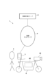
- FIG. 1 is a schematic diagram of a route guidance system 1.
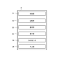
- FIG. 2 is a block diagram illustrating a configuration of a mobile communication terminal 3.
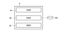
- FIG. 2 is a block diagram illustrating the configuration of a route planning server 5.
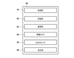
- FIG. 2 is a block diagram illustrating the configuration of an in-vehicle device 40 according to the first embodiment.
- FIG. 11 is a block diagram illustrating the configuration of an in-vehicle device 40 according to a third embodiment.
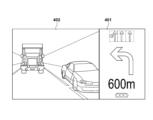
- FIG. 13 is a diagram illustrating an example of a guidance screen that provides guidance for changing course to the left.
- FIG. 1 is a schematic diagram of a route guidance system 1.
- FIG. 2 is a block diagram illustrating a configuration of a mobile communication terminal 3.
- FIG. 2 is a block diagram illustrating the configuration of a route planning server 5.
- FIG. 2 is a block diagram illustrating the configuration of an in-vehicle device 40 according to the first embodiment.
- FIG. 11 is a block diagram illustrating the configuration of an in
- FIG. 13 is a diagram illustrating an example of a guidance screen that provides guidance for changing course to the right.
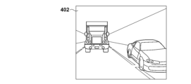
- 4 is a diagram illustrating an example of an image captured by an in-vehicle camera 44.
- FIG. 13 is a diagram illustrating an example of a rear image extracted when a leftward lane change is announced.
- FIG. 13 is a diagram illustrating an example of a rear image extracted when a rightward lane change is announced;
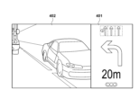
- FIG. 13 is a diagram illustrating an example of a guidance screen that provides guidance for changing course to the left when the distance to the course change point is below a threshold value.
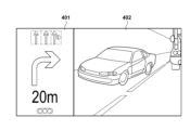
- FIG. 13 is a diagram illustrating an example of a guidance screen that provides guidance to change course to the right when the distance to the course change point is below a threshold value.
- FIG. 13 is a diagram illustrating an example of receiving an image directly captured from a roadside camera 7 according to a third modified example.
- FIG. 13 is a diagram illustrating an example of receiving an image captured by a roadside camera 7 from an external device 8 according to a third modified example.
- FIG. 13 is a diagram illustrating a guidance screen that provides guidance with a warning on changing course to the right when the distance to the course change point exceeds a threshold value in the first modified example.
- FIG. 13 is a diagram illustrating a guidance screen that provides guidance with a warning on changing course to the right when the distance to the course change point is below a threshold value according to the first modified example.
- the embodiment described below is an example of a route guidance device in which the present invention is applied to a mobile communication terminal that is mounted on a saddle-type vehicle in which a driver rides and that presents information related to route guidance to a destination.
- the present invention can be applied to any device that is capable of presenting information related to route guidance.
- the route guidance system 1 is a system that provides a route guidance service in which a mobile communication terminal 3 provides route guidance to a driver 2 who drives a saddle-type vehicle 4, according to information on a route to a destination planned by a route planning server 5 (hereinafter referred to as route guidance information).
- the route planning server 5 is a server that is communicatively connected to the mobile communication terminals 3 via a communication network 6, and generates route guidance information regarding a route from a starting point to a destination inputted in each mobile communication terminal 3.
- each driver 2 is a driver of a saddle-type vehicle 4.
- the mobile communication terminal 3 is a mobile terminal such as a smartphone used by the driver 2.
- the mobile communication terminal 3 is equipped with a display device, a wireless communication device, and an input device, and functions as a client capable of sending and receiving information to and from the route planning server 5, etc.
- Each saddle-type vehicle 4 is equipped with an in-vehicle device 40 that controls the overall operation of the vehicle.
- the in-vehicle device 40 is equipped with a wireless communication device that can communicate with the mobile communication terminal 3, an ECU that controls the drive system of the saddle-type vehicle 4, etc.
- the mobile communication terminal 3 and the in-vehicle device 40 are communicatively connected.
- the mobile communication terminal 3 has an application for providing route guidance services installed, and can function as a route guidance device that provides route guidance from a departure point to a destination according to route guidance information provided by the route planning server 5.
- the vehicle driven by the driver 2 is described as a saddle-type vehicle (motorcycle).
- the present invention is not limited to driving a saddle-type vehicle, and can be used when driving any moving vehicle operated by a driver 2 other than a saddle-type vehicle, such as a passenger car or a freight vehicle.
- the mobile communication terminal 3 includes a control unit 31, a storage unit 32, a communication unit 33, a display unit 34, a GNSS (Global Navigation Satellite System) sensor 35, and an input unit 36.
- the control unit 31 is a processor represented by a CPU, and executes a program stored in the storage unit 32.
- the storage unit 32 is a storage device such as a RAM or a ROM.
- the programs stored in the storage unit 32 also include an application program (hereinafter, sometimes referred to as a route guidance application) for using the route guidance service of this embodiment.
- the application program may be downloaded from a server such as the route planning server 5 or an application distribution server, or may be distributed on a storage medium such as a CD-ROM.
- the communication unit 33 is a wireless communication device capable of communicating with the route planning server 5 via the communication network 6.
- the communication unit 33 also includes a wireless communication device capable of directly communicating with the in-vehicle device 40.
- the display unit 34 is an electronic image display device (display) with an input function, for example a touch panel display.
- the GNSS sensor 35 is a sensor that detects the current position of the mobile communication terminal 3.
- the input unit 36 is various user interfaces that accept operational inputs possessed by the mobile communication terminal 3.
- the various user interfaces include operating members such as switches provided on the mobile communication terminal 3, and sensors for detecting touch inputs to the display unit 34.
- FIG. 3A is a block diagram of the in-vehicle device 40 according to this embodiment.
- the in-vehicle device 40 includes a control unit 41, a storage unit 42, a communication unit 43, and an in-vehicle camera 44.
- the control unit 41 is a processor represented by a CPU, and executes a program stored in the storage unit 42.
- the storage unit 42 is a storage device such as a RAM or a ROM.
- the programs stored in the storage unit 42 include a program for performing information communication with the mobile communication terminal 3.
- the communication unit 43 is a wireless communication device capable of directly communicating with the mobile communication terminal 3.
- the in-vehicle camera 44 is a camera equipped with an optical system such as a lens and an imaging sensor, and is capable of capturing images.
- the in-vehicle camera 44 may be configured to be built into the saddle-type vehicle 4 in advance, or may be attached to the outside of the saddle-type vehicle 4 afterwards. In this embodiment, the in-vehicle camera 44 is installed to capture an image behind the saddle-type vehicle 4.
- Example of the configuration of the route planning server 5 2B is a block diagram of the route planning server 5.
- the route planning server 5 includes a control unit 51, a storage unit 52, and a communication unit 53.
- the control unit 51 is a processor such as a CPU, and executes a program stored in the storage unit 52.
- the storage unit 52 is a storage device such as a RAM, a ROM, or a hard disk.
- the communication unit 53 is a wired or wireless communication device capable of communicating with the mobile communication terminal 3 via the communication network 6.
- a database (DB) 521 is illustrated as an example of data stored in the memory unit 52.
- the DB 521 is a DB (hereinafter referred to as a road DB) in which information on roads on which the saddle-type vehicle 4 can travel is registered.
- the information (road information) stored in the road DB 521 includes information on the position, address, gradient, surrounding landmarks, etc. of each road, as well as traffic rules that must be observed for each road and traffic conditions (traffic jam conditions and accident occurrence conditions) obtained in real time.
- the control unit 51 When the control unit 51 receives at least the departure point and destination information along with a route guidance request from the mobile communication terminal 3, it plans a route from the departure point to the destination based on road information managed in the road DB 521, generates route guidance information, and sends it back to the mobile communication terminal 3.
- the departure point and destination information are each input by the driver 2 into the mobile communication terminal 3.
- the departure point information can use information on the current location of the mobile communication terminal 3 acquired by the GNSS sensor 35 without input from the driver 2.
- the control unit 31 of the mobile communication terminal 3 uses the route guidance information to provide route guidance to the driver 2.
- Route guidance is provided using information displayed on the display unit 34.
- the route guidance display includes a display in which information about the route specified by the route guidance information, the current location of the saddle riding vehicle 4, and the direction in which the saddle riding vehicle 4 is facing are superimposed on map information around the current location of the mobile communication terminal 3 (saddle riding vehicle 4).
- the route guidance display also includes a route change guidance display that is presented when the saddle riding vehicle 4 is at an intersection where it is necessary to turn right or left, or at a point where it is necessary to stay in a specific lane.
- route change points such points where route change guidance is necessary will be referred to as "route change points.”
- the control unit 31 determines that route change guidance should be provided.
- Approaching a route change point may be provided, for example, on the condition that the distance between the route change point and the saddle riding vehicle 4 falls below a predetermined distance threshold.
- Route change guidance is provided in multiple stages, such as by notifying the driver that a route change is necessary and encouraging the driver to prepare for the route change, or by notifying the driver of the timing when a route change is actually required.
- a screen is displayed in which a direction indication image indicating the direction of the lane change and an image (rear image) showing the situation behind the saddle-type vehicle 4 captured by the in-vehicle camera 44 are arranged side by side.
- the direction indication image may be an image presented in a so-called turn-by-turn display.
- the screen displayed on the display unit 34 can be configured, for example, as shown in Figs. 4A and 4B.
- Fig. 4A illustrates a screen displayed when guiding a lane change to the left
- Fig. 4B illustrates a screen displayed when guiding a lane change to the right.
- the screen presented when guiding a lane change (hereinafter referred to as the guidance screen) is configured so that the direction indication image 401 and rear image 402 are arranged horizontally side by side, allowing the driver 2 to check both at the same time. Therefore, when guiding a lane change, the control unit 31 sends a request for an image captured by the on-board camera 44 to the saddle-type vehicle 4 via the communication unit 33, and acquires the image.
- the arrangement of the direction indication image 401 and rear image 402 on the guidance screen differs depending on the direction of the lane change. More specifically, the rear image 402 is arranged on the guidance screen on the side of the lane change destination, i.e., the side on which the saddle riding type vehicle 4 is traveling as viewed from the driver 2. Therefore, on the guidance screen providing guidance for a lane change to the left in FIG. 4A, the rear image 402 is arranged on the left and the direction indication image 401 is arranged on the right. On the other hand, on the guidance screen providing guidance for a lane change to the right in FIG. 4B, the rear image 402 is arranged on the right and the direction indication image 401 is arranged on the left. In this way, the driver can intuitively and easily check, via the guidance screen, whether there is a vehicle traveling behind the lane change destination and the distance between the vehicles, etc.
- the rear image 402 arranged on the guidance screen is generated by extracting an image of a partial area from the image captured by the on-board camera 44.
- the image captured of the rear captures the area directly behind the saddle riding type vehicle 4 at the center of the angle of view as shown in FIG. 5A. Therefore, the image captured by the on-board camera 44 captures both the left and right rear objects of the saddle riding type vehicle 4 within the angle of view, and therefore includes information that is unnecessary for the purpose of checking either the left rear or the right rear.
- the driver 2 when changing course to the left, the driver 2 should mainly check the vehicle that is present to the left rear of the saddle riding type vehicle 4, so there is little need to present information on the object on the right rear. From another perspective, it is not preferable to present information on the object on the right rear as the rear image 402, since presenting the information on the object on the right rear may cause the driver 2 to misjudge the situation behind.
- rear image 402 is generated by extracting an image of an area corresponding to the direction of lane change from the image captured by the on-board camera. More specifically, when guiding a lane change to the left, control unit 31 generates rear image 402 by extracting an area capturing an object to the left rear, including directly behind saddle-type vehicle 4, from the image captured by on-board camera 44, as shown in FIG. 5B. Also, when guiding a lane change to the right, control unit 31 generates rear image 402 by extracting an area capturing an object to the right rear, including directly behind saddle-type vehicle 4, from the image captured by on-board camera 44, as shown in FIG. 5C.
- the rear position where the driver 2 should check the situation varies depending on the distance to the lane change point where the lane change is to be completed. That is, when a notice of a lane change is given, it is preferable that there is a sufficient distance to the lane change point and that the driver 2 can check a wide area behind the lane change destination where there are vehicles that may require attention when changing lanes thereafter. For example, since there is a possibility that a following vehicle directly behind may change lanes to the lane change destination, it is preferable that the driver 2 can check the situation including not only the rear of the lane change destination but also the area directly behind.
- the driver 2 can check the area closer to the saddle type vehicle 4 where there are vehicles that are likely to enter the lane change destination. That is, at the time when the lane change is actually to be made, there is a low possibility of contact with a vehicle traveling far behind the saddle type vehicle 4, and there is little need to notify the driver 2. For example, when changing lanes to the left, there is a possibility that a vehicle traveling closely in the left lane may be hit, so it is very convenient for the driver 2 to be able to check the situation in the rear image 402 before moving his/her gaze to the side mirror.
- the rear image 402 when generating the rear image 402, the area extracted from the image captured by the on-board camera 44 is changed depending on the distance from the lane change point. More specifically, in the embodiment shown in FIG. 5A in which the image captured by the on-board camera 44 is captured, for example, when the distance from the lane change point exceeds a predetermined threshold, the rear image 402 is generated by extracting the entire area near the lane change destination as shown in FIGS. 5B and 5C. On the other hand, when the distance from the lane change point is below the threshold, the rear image 402 is generated by extracting an area near the saddle riding vehicle 4 from the area near the lane change destination as shown in FIG. 6.
- the area near the saddle riding vehicle 4 is an area in which a subject that is at a distance less than a predetermined distance from the saddle riding vehicle 4, such as to the side of the saddle riding vehicle 4, is captured.
- FIG. 6A illustrates an example of a guidance screen that is displayed when a lane change should be made to the left
- FIG. 6B illustrates an example of a guidance screen that is displayed when a lane change should be made to the right.
- the rear image 402 of the guidance screen that is displayed when the distance to the lane change point falls below a threshold is configured to present the driver 2 with a more limited view of the rearward situation than when the distance exceeds the threshold.
- the area from which the rear image 402 is extracted is described as being controlled to differ depending on whether the distance to the lane change point exceeds a threshold value. More specifically, if the distance to the lane change point exceeds the threshold value, an image in which the entire area closer to the lane change destination is extracted is used as the rear image 402, and if the distance is equal to or less than the threshold value, an image in which a smaller area closer to the saddle-type vehicle 4 is extracted is used as the rear image 402.
- the implementation of the present invention is not limited to this, and for example, the extracted area may be controlled to be narrower as the distance to the lane change point becomes shorter, so as to focus on a subject closer to the saddle-type vehicle 4.
- ⁇ Display control processing> a specific display control process for route guidance performed in the route guidance application in the mobile communication terminal 3 of this embodiment will be described with reference to the flowchart in Fig. 7.
- the process corresponding to the flowchart can be realized by the control unit 31 reading out a corresponding processing program recorded in, for example, the ROM, expanding it in the RAM, and executing it.
- the control unit 31 determines whether or not to provide lane change guidance. Specifically, the control unit 31 determines whether or not the saddle riding vehicle 4 has approached the next lane change point while traveling along the route defined in the route guidance information, and the distance to that point has fallen below a predetermined distance threshold. That is, the control unit 31 obtains information on the current location of the saddle riding vehicle 4 (mobile communication terminal 3), derives the distance to the next lane change point, and makes the determination in this step by comparing that distance with the distance threshold.
- the distance threshold used in the determination in this step is set to a distance that allows some leeway to the lane change point, such as 600 m. If the control unit 31 determines that lane change guidance should be provided, the process proceeds to S702, and if it determines that lane change guidance should not be provided, the process proceeds to S705.
- the control unit 31 judges whether the distance to the lane change point has fallen below a threshold indicating the distance at which the lane change should actually be made.
- the threshold used in the judgment in this step is set to the distance at which the lane change operation should actually be initiated, for example 20 m. If the control unit 31 judges that the distance to the lane change point has fallen below the threshold, it transfers the process to S703, and if it judges that the distance is equal to or greater than the threshold, it transfers the process to S704.
- the control unit 31 generates a guidance screen and displays it on the display unit 34. More specifically, the control unit 31 extracts an image of the immediate area near the lane change destination from the image captured by the in-vehicle camera 44 received from the saddle-riding vehicle 4 to generate a rear image. The control unit 31 then generates a guidance screen in which the rear image and a direction indication image are arranged horizontally and displays it on the display unit 34. For example, when turning left, the control unit 31 extracts an image of an area capturing a subject near the saddle-riding vehicle 4 at the left rear as the rear image, as shown in FIG. 6B.
- the control unit 31 determines whether the distance to the lane change point is equal to or greater than the threshold. If it is determined in S702 that the distance to the lane change point is equal to or greater than the threshold, the control unit 31 generates a guidance screen in S704 and displays it on the display unit 34. More specifically, the control unit 31 extracts an image of the immediate area near the lane change destination from the image captured by the in-vehicle camera 44 received from the saddle riding vehicle 4 to generate a rear image. The control unit 31 then generates a guidance screen in which the rear image and a direction indication image are arranged horizontally and displays it on the display unit 34. For example, when turning left, the control unit 31 extracts an image of the area including the left rear and directly behind the saddle riding vehicle 4 as the rear image, as shown in FIG. 4A.
- the control unit 31 displays normal route guidance in S705.
- the display may display route and current location information superimposed on map information, or may display images captured by the on-board camera 44 that are not extracted.
- the route guidance device of this embodiment can assist the driver in checking behind the vehicle when changing lanes, thereby contributing to improved safety when driving a vehicle. More specifically, by checking the display when receiving guidance on changing lanes, the driver can grasp the direction in which to change lanes and the situation behind the vehicle without moving his or her eyes.
- the area extracted from the image captured by the on-board camera 44 changes depending on the direction of the lane change, and the image of that area is displayed positioned on the side of the lane change destination, allowing the driver to intuitively grasp the situation behind the lane change destination.
- the extracted area changes depending on the distance to the lane change point, it is possible to appropriately notify the driver of subjects that should be noted at each stage from when the driver is made aware of the lane change to when the lane change is actually made.
- the guidance screen composed of a direction indication image and a rear image is displayed on the display unit 34.
- the perception of the distance between the vehicle and the vehicle traveling behind may differ between the case where the driver checks the rear by looking at the rear image on the guidance screen and the case where the driver checks the rear visually.
- the distance between the saddle riding type vehicle 4 and each of objects such as vehicles and people captured within the angle of view based on the captured image may be derived, and if there is an object approaching within a predetermined distance, a warning to that effect may be given on the guidance screen.
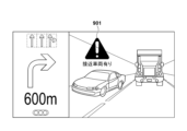
- the warning on the guidance screen may be given by superimposing a warning display 901 or 902 at a position corresponding to the object in the rear image, as shown in Figs. 9A and 9B, for example. As shown in the figures, such a warning regarding the approach of an object may be given regardless of the distance to the course change point.
- the predetermined distance which is the criterion for determining whether or not to give a warning, may be set to a fixed value such as 20 m, or may be set to a value that varies depending on the vehicle speed of the saddle riding type vehicle 4 (the longer the vehicle speed is faster, and the shorter the vehicle speed is slower).
- the route planning server 5 generates route guidance information based on information on the departure point and the destination, and the mobile communication terminal 3 receives the route guidance information and provides route guidance.
- the control unit 31 of the mobile communication terminal 3 may generate route guidance information for reaching the destination from the departure point by using road information previously stored in the storage unit 32.
- the present invention can also be realized by the mobile communication terminal 3 that acquires images captured by the in-vehicle camera 44 without communicating with the route planning server 5.
- the display control process is performed by the mobile communication terminal 3 connected to the in-vehicle device 40 of the saddle riding type vehicle 4, but the present invention is not limited to this.
- the present invention may be realized by executing the display control process in the in-vehicle device 40 of the saddle riding type vehicle 4 and displaying a guidance screen using a display device (display) such as a meter panel or a route guidance display provided in the saddle riding type vehicle 4.
- Example of configuration of in-vehicle device 40 3B is a block diagram of the in-vehicle device 40 according to this embodiment.
- the in-vehicle device 40 includes a display unit 45 and a GNSS sensor 46 used for various displays including guidance for changing routes.
- the display unit 45 is an electronic image display device (display) equipped with an input function, and is, for example, a touch panel display.
- the GNSS sensor 46 is a sensor that detects the current position of the saddle-type vehicle 4.
- the communication unit 43 is a wireless communication device capable of communicating with the route planning server 5.
- the control unit 41 may perform the display control processing shown in embodiment 1 and control the display of a guidance screen on the display unit 45. That is, prior to the display control processing, the control unit 41 transmits information on the departure point and destination to the route planning server 5 to obtain route guidance information, and performs route guidance based on the route guidance information and the current location of the saddle-type vehicle 4. The control unit 41 displays a guidance screen on the display unit 45 when a course change is made, displays route guidance in normal times, or displays an image captured by the in-vehicle camera 44.
- the in-vehicle device 40 of the saddle-type vehicle 4 receives route guidance information generated by the route planning server 5 and provides route guidance.
- the generation of the route guidance information may be performed by the in-vehicle device 40.
- the route guidance information may be received from the mobile communication terminal 3.
- the direction indication image and the rear image are arranged horizontally on the guidance screen displayed to guide the driver to change course, but the present invention is not limited to this. From the viewpoint of assisting the driver 2 in checking the rear when receiving guidance on changing course, it is sufficient to present the direction indication image and the rear image on the same screen, and the arrangement of these images on the guidance screen may be in another manner, such as vertically.
- the image used for the rear image is described as being taken by the on-board camera 44 provided on the saddle riding vehicle 4, but the implementation of the present invention is not limited to this.
- the rear image can be an image taken by a camera other than the on-board camera 44, as long as it shows at least the situation behind the saddle riding vehicle 4.
- Such cameras include roadside cameras installed at traffic lights, footbridges, etc., for example.
- the mobile communication terminal 3 and the on-board device 40 of the saddle riding vehicle 4 can receive an image taken by a roadside camera installed in the area where the saddle riding vehicle 4 is located, for example, when the mobile communication terminal 3 approaches a lane change point, and use the image for display control processing.
- the image is an image of an area including the rear of the saddle riding vehicle 4, and in the display control processing, an image of the relevant area is extracted from the surrounding image and displayed as a rear image on the guidance screen, so that the rear situation at the time of lane change can be presented to the driver 2.
- Images taken by the roadside camera 7 may be received by a direct communication connection between the roadside camera and a mobile communication terminal 3 or a saddle-type vehicle 4, as shown in Figure 8A, or may be received indirectly by a communication connection with an external device 8 that sequentially records images taken by the roadside camera, as shown in Figure 8B.
- the display control process is described as being executed by the mobile communication terminal 3 or the in-vehicle device 40, but the display control process may be executed by any information communication terminal configured to receive, for example, the execution of a route change guidance as a trigger and receive a direction indication image and a surrounding image corresponding to the route change.
- the selection process is executed by a CPU (not shown) built into the information communication terminal expanding a program of the display control process recorded in a storage device such as an HDD into a RAM or the like.
- the program of the selection process executed by the CPU may be installed in the storage device of the information communication terminal via a storage medium such as a CD-ROM.
- the route guidance device (3, 40) of the above embodiment is an image acquisition means (33, 43) for acquiring an image of the surroundings of the vehicle, including at least the rear of the vehicle;
- the display control means (31, 41) is provided for displaying, when guiding a lane change for the vehicle, a direction indication image (401) for the lane change and the surrounding image side by side on a display (34, 45).
- the driver can grasp the situation behind the vehicle without moving his/her line of sight, simply by looking at the display.
- the route guidance device of the above embodiment is The display control means changes the arrangement of the direction indication image and the surrounding image according to the direction of the lane change. According to this embodiment, the direction of the lane change can be grasped instantly.
- the route guidance device of the above embodiment is the display control means displays the direction indication image and the surrounding image side by side in a horizontal direction on the display;
- the direction indication image is displayed on the display, positioned on the lane change destination side. According to this embodiment, the driver can intuitively grasp the situation behind the vehicle on the side where the lane is to be changed.
- the route guidance device of the above embodiment The display control means extracts an area in which the subject is distributed on the lane-changing destination side from the surrounding image and displays the area on the display. According to this embodiment, it is possible to limit and present to the driver only those subjects that the driver should pay attention to.
- the route guidance device of the above embodiment the route change guidance is started prior to the vehicle reaching the route change point,
- the display control means varies an area to be extracted from the surrounding image depending on a distance between the lane change point and the vehicle. According to this embodiment, it is possible to notify the driver of subjects that require attention in a step-by-step manner from the time the driver is made aware of a lane change until the lane change is actually made.
- the route guidance device of the above embodiment The display control means narrows an area extracted from the surrounding image when a distance between the lane change point and the vehicle is shorter than a threshold value. According to this embodiment, information that requires confirmation can be effectively communicated to the driver.
- the display control means extracts an area close to the vehicle from the surrounding image and displays the area on the display. According to this embodiment, information that requires confirmation can be effectively communicated to the driver.
- the route guidance device of the above embodiment Further comprising an information acquisition means for acquiring route guidance information, The display control means determines whether or not to provide guidance on the route change based on the route guidance information. According to this embodiment, route change guidance can be provided at an appropriate timing during route guidance.
- the route guidance device of the above embodiment Further comprising a communication means (33, 43) for communicating with an external device;
- the information acquisition means acquires the route guidance information received in response to the communication means transmitting at least the departure point and destination of the vehicle to the external device. According to this embodiment, it is possible to present information that allows the driver to efficiently check behind the vehicle when changing course by utilizing route guidance information planned by an external device.
- the route guidance device of the above embodiment a generating means (31, 41) for determining a route of the vehicle based on at least a departure point and a destination point of the vehicle and generating the route guidance information;
- the information acquiring means acquires the route guidance information generated by the generating means. According to this embodiment, information that enables efficient rearward confirmation when changing course based on the determined route plan can be presented.
- the route guidance device of the above embodiment is an image captured by an on-board camera (44) mounted on the vehicle. According to this embodiment, the driver can be appropriately notified of the situation behind the vehicle.
- the route guidance device of the above embodiment Further comprising a communication means for communicating with an external device;
- the surrounding image is an image captured by a roadside camera (7),
- the image acquisition means acquires images received by the communication means from the roadside cameras arranged in an area where the vehicle is present. According to this embodiment, it is possible to appropriately notify the driver while overlooking the area behind the vehicle.
- the route guidance method of the above embodiment is The route guidance device an image acquisition step of acquiring an image of the surroundings of the vehicle, the image including at least the rear of the vehicle;
- the method further comprises a display control step (S703, S704) for, when guiding a lane change for the vehicle, displaying a direction indication image for the lane change and the surrounding image side by side on the display.
- a display control step S703, S704 for, when guiding a lane change for the vehicle, displaying a direction indication image for the lane change and the surrounding image side by side on the display.
- the computer-readable storage medium of the above embodiment includes: On the computer, An image acquisition process for acquiring an image of the surroundings of the vehicle, the image including at least the rear of the vehicle; a display control process for displaying a direction indication image for the lane change and the surrounding image side by side on a display when guiding a lane change of the vehicle; A program to execute the above was stored. According to this embodiment, when a route change is being guided, the driver can grasp the situation behind the vehicle without moving his/her line of sight, simply by looking at the display.
- the program of the above embodiment is On the computer, An image acquisition process for acquiring an image of the surroundings of the vehicle, the image including at least the rear of the vehicle; a display control process for displaying a direction indication image for the lane change and the surrounding image side by side on a display when guiding a lane change of the vehicle; Execute the command.
- an image acquisition process for acquiring an image of the surroundings of the vehicle, the image including at least the rear of the vehicle; a display control process for displaying a direction indication image for the lane change and the surrounding image side by side on a display when guiding a lane change of the vehicle; Execute the command.
- the driver can grasp the situation behind the vehicle without moving his/her line of sight, simply by looking at the display.
- the saddle-type vehicle (4) of the above embodiment is A saddle-type vehicle including a display (45), a camera (44), and a control device (41),
- the control device includes: an image acquisition unit that acquires an image of the surroundings of the saddle riding type vehicle, the image including at least an area behind the saddle riding type vehicle, captured by the camera;
- the display control means is configured to, when providing guidance on a change in course of the saddle riding type vehicle, display a direction indication image (401) for the change in course and the surrounding image side by side on the display.
- a direction indication image 401
- the driver can grasp the situation behind the vehicle without moving his/her line of sight, simply by looking at the display.
Landscapes
- Engineering & Computer Science (AREA)
- Radar, Positioning & Navigation (AREA)
- Remote Sensing (AREA)
- Automation & Control Theory (AREA)
- Physics & Mathematics (AREA)
- General Physics & Mathematics (AREA)
- Multimedia (AREA)
- Mechanical Engineering (AREA)
- Signal Processing (AREA)
- Navigation (AREA)
- Traffic Control Systems (AREA)
Abstract
Description
車両の後方を少なくとも含む、前記車両の周辺画像を取得する画像取得手段と、
前記車両の進路変更を案内する場合に、当該進路変更の方向指示画像と前記周辺画像とを並べてディスプレイに表示する表示制御手段と、を備える、
ことを特徴とする経路案内装置が提供される。
以下、添付図面を参照して実施形態を詳しく説明する。なお、以下の実施形態は特許請求の範囲に係る発明を限定するものではなく、また実施形態で説明されている特徴の組み合わせの全てが発明に必須のものとは限らない。実施形態で説明されている複数の特徴のうち二つ以上の特徴は任意に組み合わされてもよい。また、同一若しくは同様の構成には同一の参照番号を付し、重複した説明は省略する。
図1は経路案内システム1の概略図である。経路案内システム1は、経路計画サーバ5によって計画された目的地までの経路の情報(以下、経路案内情報として言及)に従って、携帯通信端末3が鞍乗型車両4を運転する運転者2に経路案内を行う経路案内サービスを提供するシステムである。経路計画サーバ5は、通信ネットワーク6を介して携帯通信端末3と通信可能に接続され、各携帯通信端末3において入力された出発地から目的地までの経路に関する経路案内情報を生成するサーバである。
図2Aは、携帯通信端末3のブロック図である。携帯通信端末3は、制御部31、記憶部32、通信部33、表示部34、GNSS(Global Navigation Satellite System)センサ35及び入力部36を含む。制御部31は、CPUに代表されるプロセッサであり、記憶部32に記憶されたプログラムを実行する。記憶部32は、RAM、ROMなどの記憶デバイスである。記憶部32に記憶されたプログラムには、本実施形態の経路案内サービスを利用するためのアプリケーション(以下、経路案内アプリケーションと言及する場合がある)プログラムも含まれる。アプリケーションプログラムは、経路計画サーバ5やアプリケーション配布サーバ等のサーバからダウンロードされてもよいし、CD-ROM等の記憶媒体で配布されてもよい。
図3Aは、本実施形態に係る車載装置40のブロック図である。車載装置40は、制御部41、記憶部42、通信部43、車載カメラ44を含む。制御部41は、CPUに代表されるプロセッサであり、記憶部42に記憶されたプログラムを実行する。記憶部42は、RAM、ROMなどの記憶デバイスである。記憶部42に記憶されたプログラムには、携帯通信端末3と情報通信を行うプログラムを含む。通信部43は、携帯通信端末3と直接通信可能な無線通信装置である。車載カメラ44は、レンズ等の光学系と撮像センサを備えたカメラであり、画像を撮影可能である。車載カメラ44は、予め鞍乗型車両4に内蔵されて構成されるものであってもよいし、後付けで鞍乗型車両4の外部に装着されるものであってもよい。本実施形態では、車載カメラ44は鞍乗型車両4の後方を撮影するよう設置されているものとする。
図2Bは、経路計画サーバ5のブロック図である。経路計画サーバ5は、制御部51、記憶部52、通信部53を含む。制御部51は、CPUに代表されるプロセッサであり、記憶部52に記憶されたプログラムを実行する。記憶部52は、RAM、ROM、ハードディスクなどの記憶デバイスである。通信部53は、通信ネットワーク6を介して携帯通信端末3と通信可能な有線又は無線の通信装置である。
以下、進路変更の案内表示について、図を用いて詳細を説明する。
ここで、案内画面に配置される後方画像402は、車載カメラ44により撮影された画像のうちの一部の領域の画像を抽出して生成される。本実施形態に示されるように1つの車載カメラ44が鞍乗型車両4に装着される態様では、後方を撮影した画像は図5Aに示されるように鞍乗型車両4の真後ろを画角の中心に捉えている。故に、車載カメラ44が撮影した画像には、鞍乗型車両4の左後方及び右後方の被写体の両方が画角内に捉えられているため、左後方または右後方のいずれかを確認する用途では不要な情報を含む。即ち、左方向への進路変更時には、運転者2が確認すべきは主として鞍乗型車両4の左後方に存在する車両であるため、右後方の被写体の情報は提示する必要性が低い。別の観点では、右後方の被写体の情報は、提示することにより運転者2が後方の状況を見誤る可能性があるため、後方画像402として提示することが好ましくない。
以下、本実施形態の携帯通信端末3において、経路案内アプリケーションにおいて経路案内に係り行われる表示制御処理について、図7のフローチャートを参照して具体的な処理を説明する。該フローチャートに対応する処理は、制御部31が、例えばROMに記録されている対応する処理プログラムを読み出し、RAMに展開して実行することにより実現することができる。
上述した実施形態では進路変更の案内を行う場合に、方向指示画像と後方画像とで構成された案内画面を表示部34に表示するものとして説明した。一方で、案内画面の後方画像を運転者が見て後方確認する場合と、目視で運転者が後方確認する場合とでは、後方を走行中の車両との車間距離の感じ方が異なることがある。このため、撮影画像に基づいて画角内に捉えられている車両や人物等のオブジェクトのそれぞれについて鞍乗型車両4との距離を導出し、所定距離以下に接近しているオブジェクトが存在する場合にはその旨を案内画面において警告するよう構成してもよい。案内画面における警告は、例えば図9Aや9Bに示されるように、後方画像中の該当のオブジェクトと対応する位置に警告表示901または902を重畳することにより行うことができる。図示されるようにオブジェクト接近に係るこのような警告は、進路変更地点までの距離によらず行うように構成されるものであってよい。また警告するか否かの判断基準となる所定距離は、例えば20mのように固定の値に設定されてもよいし、鞍乗型車両4の車速に応じて変動する値(車速が速ければ長くなり、遅ければ短くなる)に設定されてもよい。
上述した実施形態では、出発地及び目的地の情報に基づいて経路計画サーバ5が経路案内情報を生成し、当該経路案内情報を携帯通信端末3が受信して経路案内を行う態様を説明したが、本発明の実施はこれに限られるものはない。出発地から目的地に至るための経路案内情報の生成は、携帯通信端末3において制御部31が、予め記憶部32に記憶された道路情報を用いて行うものであってもよい。即ち、本発明は、経路計画サーバ5に通信接続することなく、車載カメラ44の撮影画像を取得する携帯通信端末3により実現することもできる。
上述した実施形態では、鞍乗型車両4が有する車載装置40と接続した携帯通信端末3が表示制御処理を行うものとして説明したが、本発明の実施はこれに限られるものではない。本発明は、表示制御処理が鞍乗型車両4の備える車載装置40において実行され、鞍乗型車両4に設けられたメーターパネルや経路案内用ディスプレイ等の表示装置(ディスプレイ)を用いて案内画面の表示を行うことにより実現されるものであってもよい。
図3Bは、本実施形態に係る車載装置40のブロック図である。車載装置40は、実施形態1にて説明した制御部41、記憶部42、通信部43、車載カメラ44に加え、進路変更の案内を含む各種の表示に用いられる表示部45とGNSSセンサ46とを含む。表示部45は、入力機能を備えた電子画像の表示装置(ディスプレイ)であり、例えば、タッチパネル式ディスプレイである。GNSSセンサ46は鞍乗型車両4の現在位置を検知するセンサである。また本実施形態では通信部43は、経路計画サーバ5と通信可能な無線通信装置である。
上述した実施形態では、進路変更を案内するために表示される案内画面において方向指示画像と後方画像とが水平方向に並べて配置されるものとして説明したが、本発明の実施はこれに限られるものではない。進路編子の案内時に運転者2の後方確認を補助するとの観点では、方向指示画像と後方画像とを同一画面で提示すればよく、案内画面におけるこれらの画像の配置は、例えば垂直方向に並べられる等、他の態様を採用することもできる。
上述した実施形態では後方画像に利用される画像は、鞍乗型車両4に設けられた車載カメラ44が撮影するものとして説明したが、本発明の実施はこれに限られるものではない。後方画像は、少なくとも鞍乗型車両4の後方の状況を示すものであれば、車載カメラ44以外のカメラにより撮影された画像を利用することもできる。このようなカメラには、例えば信号機や歩道橋等に設置された路側カメラも含まれる。携帯通信端末3や鞍乗型車両4が有する車載装置40は、例えば進路変更地点に近接したことを契機として、当該鞍乗型車両4が存在するエリアに配置された路側カメラが撮影した画像を受信して表示制御処理に利用することができる。当該画像は、鞍乗型車両4の後方を含む領域を撮影した画像であり、表示制御処理において、当該周辺画像から該当の領域の画像を抽出して後方画像として案内画面に含めて表示することにより、進路変更時の後方の状況を運転者2に提示することができる。路側カメラ7の撮影した画像の取得は、図8Aに示されるように当該路側カメラと携帯通信端末3または鞍乗型車両4が直接通信接続することにより受信するものであってもよいし、図8Bに示されるように当該路側カメラの撮影した画像を順次記録している外部装置8と通信接続することにより間接的に受信するものであってもよい。
上述した実施形態及び変形例では、携帯通信端末3または車載装置40が表示制御処理を実行するものとして説明したが、表示制御処理は、例えば進路変更の案内実行をトリガとして受け取り、当該進路変更に対応する方向指示画像と周辺画像とを受信可能に構成された任意の情報通信端末において実行されるものであってもよい。この場合、情報通信端末が内蔵する不図示のCPUが、HDD等の記憶装置に記録された表示制御処理のプログラムをRAM等に展開することにより、選択処理が実行される。ここで、CPUが実行する選択処理のプログラムは、CD-ROM等の記憶媒体を介して情報通信端末の記憶装置にインストールされるものであってもよい。
上記実施形態は、少なくとも以下の経路案内装置、経路案内方法、記憶媒体、プログラム及び鞍乗型車両を開示する。
車両の後方を少なくとも含む、前記車両の周辺画像を取得する画像取得手段(33, 43)と、
前記車両の進路変更を案内する場合に、当該進路変更の方向指示画像(401)と前記周辺画像とを並べてディスプレイ(34, 45)に表示する表示制御手段(31, 41)と、を備える。
この実施形態によれば、進路変更の案内時にディスプレイの表示のみで運転者が車両後方の状況を視線を移動させずに把握することができる。
前記表示制御手段は、前記進路変更の方向に応じて前記方向指示画像と前記周辺画像の配置を変更する。
この実施形態によれば、進路変更の方向を瞬時に把握することができる。
前記表示制御手段は、前記方向指示画像と前記周辺画像とを水平方向に並べて前記ディスプレイに表示し、
前記方向指示画像は、前記ディスプレイにおいて前記進路変更先側に配置されて表示される。
この実施形態によれば、直感的に進路変更先側の後方の状況を運転者に把握させることができる。
前記表示制御手段は、前記進路変更先側の被写体が分布する領域を前記周辺画像から抽出して前記ディスプレイに表示する。
この実施形態によれば、運転者が注目すべき被写体を限定して提示することができる。
前記進路変更の案内は、前記車両の進路変更地点への到達に先立って開始されるものであり、
前記表示制御手段は、前記進路変更地点と前記車両との距離に応じて前記周辺画像から抽出する領域を異ならせる。
この実施形態によれば、進路変更を運転者に把握させてから実際に進路変更を行うまでに段階的に注目すべき被写体を通知することができる。
前記表示制御手段は、前記進路変更地点と前記車両との距離が閾値より短い場合に、前記周辺画像から抽出する領域を狭小にする。
この実施形態によれば、確認が必要となる情報を効果的に運転者に伝達することができる。
前記表示制御手段は、前記進路変更地点と前記車両との距離が閾値より短い場合に、前記周辺画像中の前記車両に近い領域を抽出して前記ディスプレイに表示する。
この実施形態によれば、確認が必要となる情報を効果的に運転者に伝達することができる。
経路案内情報を取得する情報取得手段をさらに備え、
前記表示制御手段は、前記経路案内情報に基づいて前記進路変更を案内するか否かを判断する。
この実施形態によれば、経路案内中の適切なタイミングで進路変更を案内することができる。
外部装置と通信する通信手段(33, 43)をさらに備え、
前記情報取得手段は、前記通信手段が少なくとも前記車両の出発地と目的地とを前記外部装置に送信したことに応じて受信した前記経路案内情報を取得する。
この実施形態によれば、外部装置により計画された経路案内情報を利用して進路変更時に効率的に後方確認可能な情報提示を行うことができる。
少なくとも前記車両の出発地と目的地とに基づいて前記車両の経路を決定して前記経路案内情報を生成する生成手段(31, 41)をさらに備え、
前記情報取得手段は、前記生成手段により生成された前記経路案内情報を取得する。
この実施形態によれば、決定した経路計画に基づいて進路変更時に効率的に後方確認可能な情報提示を行うことができる。
前記周辺画像は、前記車両に装着された車載カメラ(44)により撮影された画像である。
この実施形態によれば、車両の後方の状況を適切に運転者に通知することができる。
外部装置と通信する通信手段をさらに備え、
前記周辺画像は、路側カメラ(7)により撮影された画像であり、
前記画像取得手段は、前記車両が存在するエリアに配置された前記路側カメラから前記通信手段が受信した画像を取得する。
この実施形態によれば、車両の後方を俯瞰する態様にて適切に運転者に通知することができる。
経路案内装置が、
車両の後方を少なくとも含む、前記車両の周辺画像を取得する画像取得工程と、
前記車両の進路変更を案内する場合に、当該進路変更の方向指示画像と前記周辺画像とを並べてディスプレイに表示する表示制御工程(S703, S704)と、を備える。
この実施形態によれば、進路変更の案内時にディスプレイの表示のみで運転者が車両後方の状況を視線を移動させずに把握することができる。
コンピュータに、
車両の後方を少なくとも含む、前記車両の周辺画像を取得する画像取得処理と、
前記車両の進路変更を案内する場合に、当該進路変更の方向指示画像と前記周辺画像とを並べてディスプレイに表示する表示制御処理と、
を実行させるプログラムを記憶した。
この実施形態によれば、進路変更の案内時にディスプレイの表示のみで運転者が車両後方の状況を視線を移動させずに把握することができる。
コンピュータに、
車両の後方を少なくとも含む、前記車両の周辺画像を取得する画像取得処理と、
前記車両の進路変更を案内する場合に、当該進路変更の方向指示画像と前記周辺画像とを並べてディスプレイに表示する表示制御処理と、
を実行させる。
この実施形態によれば、進路変更の案内時にディスプレイの表示のみで運転者が車両後方の状況を視線を移動させずに把握することができる。
ディスプレイ(45)とカメラ(44)と制御装置(41)を備える鞍乗型車両であって、
前記制御装置は、
前記カメラにより撮影された、前記鞍乗型車両の後方を少なくとも含む、前記鞍乗型車両の周辺画像を取得する画像取得手段と、
前記鞍乗型車両の進路変更を案内する場合に、当該進路変更の方向指示画像(401)と前記周辺画像とを並べて前記ディスプレイに表示する表示制御手段と、を備える。
この実施形態によれば、進路変更の案内時にディスプレイの表示のみで運転者が車両後方の状況を視線を移動させずに把握することができる。
発明は上記の実施形態に制限されるものではなく、発明の要旨の範囲内で、種々の変形・変更が可能である。
Claims (16)
- 車両の後方を少なくとも含む、前記車両の周辺画像を取得する画像取得手段と、
前記車両の進路変更を案内する場合に、当該進路変更の方向指示画像と前記周辺画像とを並べてディスプレイに表示する表示制御手段と、を備える、
ことを特徴とする経路案内装置。 - 請求項1に記載の経路案内装置であって、
前記表示制御手段は、前記進路変更の方向に応じて前記方向指示画像と前記周辺画像の配置を変更する、
ことを特徴とする経路案内装置。 - 請求項2に記載の経路案内装置であって、
前記表示制御手段は、前記方向指示画像と前記周辺画像とを水平方向に並べて前記ディスプレイに表示し、
前記方向指示画像は、前記ディスプレイにおいて前記進路変更先側に配置されて表示される、
ことを特徴とする経路案内装置。 - 請求項1に記載の経路案内装置であって、
前記表示制御手段は、前記進路変更先側の被写体が分布する領域を前記周辺画像から抽出して前記ディスプレイに表示する、
ことを特徴とする経路案内装置。 - 請求項4に記載の経路案内装置であって、
前記進路変更の案内は、前記車両の進路変更地点への到達に先立って開始されるものであり、
前記表示制御手段は、前記進路変更地点と前記車両との距離に応じて前記周辺画像から抽出する領域を異ならせる、
ことを特徴とする経路案内装置。 - 請求項5に記載の経路案内装置であって、
前記表示制御手段は、前記進路変更地点と前記車両との距離が閾値より短い場合に、前記周辺画像から抽出する領域を狭小にする、
ことを特徴とする経路案内装置。 - 請求項5に記載の経路案内装置であって、
前記表示制御手段は、前記進路変更地点と前記車両との距離が閾値より短い場合に、前記周辺画像中の前記車両に近い領域を抽出して前記ディスプレイに表示する、
ことを特徴とする経路案内装置。 - 請求項1に記載の経路案内装置であって、
経路案内情報を取得する情報取得手段をさらに備え、
前記表示制御手段は、前記経路案内情報に基づいて前記進路変更を案内するか否かを判断する、
ことを特徴とする経路案内装置。 - 請求項8に記載の経路案内装置であって、
外部装置と通信する通信手段をさらに備え、
前記情報取得手段は、前記通信手段が少なくとも前記車両の出発地と目的地とを前記外部装置に送信したことに応じて受信した前記経路案内情報を取得する、
ことを特徴とする経路案内装置。 - 請求項8に記載の経路案内装置であって、
少なくとも前記車両の出発地と目的地とに基づいて前記車両の経路を決定して前記経路案内情報を生成する生成手段をさらに備え、
前記情報取得手段は、前記生成手段により生成された前記経路案内情報を取得する、
ことを特徴とする経路案内装置。 - 請求項1乃至10のいずれか1項に記載の経路案内装置であって、
前記周辺画像は、前記車両に装着された車載カメラにより撮影された画像である、
ことを特徴とする経路案内装置。 - 請求項1に記載の経路案内装置であって、
外部装置と通信する通信手段をさらに備え、
前記周辺画像は、路側カメラにより撮影された画像であり、
前記画像取得手段は、前記車両が存在するエリアに配置された前記路側カメラから前記通信手段が受信した画像を取得する、
ことを特徴とする経路案内装置。 - 経路案内装置が、
車両の後方を少なくとも含む、前記車両の周辺画像を取得する画像取得工程と、
前記車両の進路変更を案内する場合に、当該進路変更の方向指示画像と前記周辺画像とを並べてディスプレイに表示する表示制御工程と、を備える、
ことを特徴とする経路案内方法。 - コンピュータに、
車両の後方を少なくとも含む、前記車両の周辺画像を取得する画像取得処理と、
前記車両の進路変更を案内する場合に、当該進路変更の方向指示画像と前記周辺画像とを並べてディスプレイに表示する表示制御処理と、
を実行させるプログラムを記憶したコンピュータ読取可能な記憶媒体。 - コンピュータに、
車両の後方を少なくとも含む、前記車両の周辺画像を取得する画像取得処理と、
前記車両の進路変更を案内する場合に、当該進路変更の方向指示画像と前記周辺画像とを並べてディスプレイに表示する表示制御処理と、
を実行させるプログラム。 - ディスプレイとカメラと制御装置を備える鞍乗型車両であって、
前記制御装置は、
前記カメラにより撮影された、前記鞍乗型車両の後方を少なくとも含む、前記鞍乗型車両の周辺画像を取得する画像取得手段と、
前記鞍乗型車両の進路変更を案内する場合に、当該進路変更の方向指示画像と前記周辺画像とを並べて前記ディスプレイに表示する表示制御手段と、を備える、
ことを特徴とする鞍乗型車両。
Priority Applications (3)
| Application Number | Priority Date | Filing Date | Title |
|---|---|---|---|
| JP2025522355A JPWO2024242003A1 (ja) | 2023-05-23 | 2024-05-15 | |
| DE112024002215.4T DE112024002215T5 (de) | 2023-05-23 | 2024-05-15 | Routenführungsvorrichtung, Routenführungsverfahren, Speichermedium, Programm und Grätschsitzfahrzeug |
| US19/395,168 US20260104265A1 (en) | 2023-05-23 | 2025-11-20 | Route guiding device, route guiding method, and straddle type vehicle |
Applications Claiming Priority (2)
| Application Number | Priority Date | Filing Date | Title |
|---|---|---|---|
| JP2023-084682 | 2023-05-23 | ||
| JP2023084682 | 2023-05-23 |
Related Child Applications (1)
| Application Number | Title | Priority Date | Filing Date |
|---|---|---|---|
| US19/395,168 Continuation US20260104265A1 (en) | 2023-05-23 | 2025-11-20 | Route guiding device, route guiding method, and straddle type vehicle |
Publications (1)
| Publication Number | Publication Date |
|---|---|
| WO2024242003A1 true WO2024242003A1 (ja) | 2024-11-28 |
Family
ID=93589422
Family Applications (1)
| Application Number | Title | Priority Date | Filing Date |
|---|---|---|---|
| PCT/JP2024/018054 Ceased WO2024242003A1 (ja) | 2023-05-23 | 2024-05-15 | 経路案内装置、経路案内方法、記憶媒体、プログラム及び鞍乗型車両 |
Country Status (4)
| Country | Link |
|---|---|
| US (1) | US20260104265A1 (ja) |
| JP (1) | JPWO2024242003A1 (ja) |
| DE (1) | DE112024002215T5 (ja) |
| WO (1) | WO2024242003A1 (ja) |
Citations (4)
| Publication number | Priority date | Publication date | Assignee | Title |
|---|---|---|---|---|
| JP2003016595A (ja) * | 2001-06-27 | 2003-01-17 | Fujitsu Ten Ltd | 走行支援装置 |
| JP2007223338A (ja) * | 2004-07-12 | 2007-09-06 | Sharp Corp | 表示システム、移動体、表示方法、表示プログラムおよびその記録媒体 |
| US20170003134A1 (en) * | 2015-06-30 | 2017-01-05 | Lg Electronics Inc. | Advanced Driver Assistance Apparatus, Display Apparatus For Vehicle And Vehicle |
| JP2021006805A (ja) * | 2019-06-27 | 2021-01-21 | 株式会社デンソー | 表示制御装置及び表示制御プログラム |
Family Cites Families (2)
| Publication number | Priority date | Publication date | Assignee | Title |
|---|---|---|---|---|
| JP6379376B2 (ja) | 2012-03-07 | 2018-08-29 | 本田技研工業株式会社 | 車両における情報表示システム |
| JP2023084682A (ja) | 2021-12-07 | 2023-06-19 | 東洋インキScホールディングス株式会社 | 高屈折率材料用硬化性樹脂、樹脂組成物、およびそれらの用途 |
-
2024
- 2024-05-15 DE DE112024002215.4T patent/DE112024002215T5/de active Pending
- 2024-05-15 JP JP2025522355A patent/JPWO2024242003A1/ja active Pending
- 2024-05-15 WO PCT/JP2024/018054 patent/WO2024242003A1/ja not_active Ceased
-
2025
- 2025-11-20 US US19/395,168 patent/US20260104265A1/en active Pending
Patent Citations (4)
| Publication number | Priority date | Publication date | Assignee | Title |
|---|---|---|---|---|
| JP2003016595A (ja) * | 2001-06-27 | 2003-01-17 | Fujitsu Ten Ltd | 走行支援装置 |
| JP2007223338A (ja) * | 2004-07-12 | 2007-09-06 | Sharp Corp | 表示システム、移動体、表示方法、表示プログラムおよびその記録媒体 |
| US20170003134A1 (en) * | 2015-06-30 | 2017-01-05 | Lg Electronics Inc. | Advanced Driver Assistance Apparatus, Display Apparatus For Vehicle And Vehicle |
| JP2021006805A (ja) * | 2019-06-27 | 2021-01-21 | 株式会社デンソー | 表示制御装置及び表示制御プログラム |
Also Published As
| Publication number | Publication date |
|---|---|
| DE112024002215T5 (de) | 2026-03-12 |
| JPWO2024242003A1 (ja) | 2024-11-28 |
| US20260104265A1 (en) | 2026-04-16 |
Similar Documents
| Publication | Publication Date | Title |
|---|---|---|
| JP6705437B2 (ja) | 脇見判定装置、脇見判定方法及び脇見判定のためのプログラム | |
| JP6387369B2 (ja) | 走行制御装置 | |
| US7777616B2 (en) | Intersection information provision system and driving assist system | |
| JP6631567B2 (ja) | 自動運転支援装置、方法及びプログラム | |
| US20170174129A1 (en) | Vehicular visual information system and method | |
| CN113401071B (zh) | 显示控制装置、显示控制方法以及计算机可读取存储介质 | |
| JP5585194B2 (ja) | 事故状況記録システム | |
| JP5327025B2 (ja) | 車両用走行案内装置、車両用走行案内方法及びコンピュータプログラム | |
| JP2016182906A (ja) | 運転支援システム | |
| JP7088899B2 (ja) | 自動運転車用情報提示装置 | |
| JP2019174459A (ja) | 制御装置、表示装置、移動体、制御方法、及びプログラム | |
| JP2009123182A (ja) | 安全確認判定装置および運転教示支援システム | |
| US10930148B2 (en) | Method and device for reminding a driver about an approach to a light signal apparatus | |
| CN111762175A (zh) | 控制装置、控制方法以及存储介质 | |
| JP2019081450A (ja) | 表示装置、表示制御方法、及びプログラム | |
| WO2020065892A1 (ja) | 車両の走行制御方法及び走行制御装置 | |
| CN113401056B (zh) | 显示控制装置、显示控制方法以及计算机可读取存储介质 | |
| JP2021092979A (ja) | 自動運転車用情報提示装置 | |
| JP7794137B2 (ja) | 表示制御装置及び表示制御システム | |
| JP3968720B2 (ja) | 車両用画像表示装置 | |
| JP7550067B2 (ja) | 情報提供方法及び情報提供システム | |
| JP2020201647A (ja) | 車両用表示制御装置、車両用表示制御方法、車両用表示制御プログラム | |
| JP2008097278A (ja) | 運転支援装置 | |
| WO2024242003A1 (ja) | 経路案内装置、経路案内方法、記憶媒体、プログラム及び鞍乗型車両 | |
| CN114651162A (zh) | 车辆驾驶挑战系统及相应的方法 |
Legal Events
| Date | Code | Title | Description |
|---|---|---|---|
| 121 | Ep: the epo has been informed by wipo that ep was designated in this application |
Ref document number: 24811010 Country of ref document: EP Kind code of ref document: A1 |
|
| ENP | Entry into the national phase |
Ref document number: 2025522355 Country of ref document: JP Kind code of ref document: A |
|
| WWE | Wipo information: entry into national phase |
Ref document number: 202517123498 Country of ref document: IN |
|
| WWE | Wipo information: entry into national phase |
Ref document number: 112024002215 Country of ref document: DE |
|
| WWP | Wipo information: published in national office |
Ref document number: 202517123498 Country of ref document: IN |
|
| WWP | Wipo information: published in national office |
Ref document number: 112024002215 Country of ref document: DE |