WO2024241663A1 - Dispositif d'assemblage pour frein à tambour, frein à tambour, et procédé d'assemblage pour frein à tambour - Google Patents
Dispositif d'assemblage pour frein à tambour, frein à tambour, et procédé d'assemblage pour frein à tambour Download PDFInfo
- Publication number
- WO2024241663A1 WO2024241663A1 PCT/JP2024/009291 JP2024009291W WO2024241663A1 WO 2024241663 A1 WO2024241663 A1 WO 2024241663A1 JP 2024009291 W JP2024009291 W JP 2024009291W WO 2024241663 A1 WO2024241663 A1 WO 2024241663A1
- Authority
- WO
- WIPO (PCT)
- Prior art keywords
- hold
- down pin
- back plate
- drum brake
- insertion hole
- Prior art date
- Legal status (The legal status is an assumption and is not a legal conclusion. Google has not performed a legal analysis and makes no representation as to the accuracy of the status listed.)
- Ceased
Links
Images





Classifications
-
- F—MECHANICAL ENGINEERING; LIGHTING; HEATING; WEAPONS; BLASTING
- F16—ENGINEERING ELEMENTS AND UNITS; GENERAL MEASURES FOR PRODUCING AND MAINTAINING EFFECTIVE FUNCTIONING OF MACHINES OR INSTALLATIONS; THERMAL INSULATION IN GENERAL
- F16D—COUPLINGS FOR TRANSMITTING ROTATION; CLUTCHES; BRAKES
- F16D65/00—Parts or details
- F16D65/02—Braking members; Mounting thereof
- F16D65/04—Bands, shoes or pads; Pivots or supporting members therefor
- F16D65/08—Bands, shoes or pads; Pivots or supporting members therefor for internally-engaging brakes
- F16D65/09—Pivots or supporting members therefor
Definitions
- the present invention relates to an assembly device for drum brakes, a drum brake, and a method for assembling a drum brake, and more specifically, to an assembly device for drum brakes, which automatically assembles an elastic member and a hold-down pin to the back plate and brake shoe of the drum brake, and a method for assembling a drum brake.
- drum brakes for vehicles had a pair of brake shoes arranged facing each other on a back plate, and the brake shoes were elastically supported on the back plate via an elastic member and a hold-down pin.
- the elastic member and hold-down pin were generally assembled by hand, with the shaft of the hold-down pin being inserted through insertion holes formed in the back plate and the brake shoe, the base end locking portion provided on the base end of the shaft being locked to the back plate, and the tip locking portion provided on the tip end of the shaft being locked to the elastic member (see, for example, Patent Document 1).
- the present invention aims to provide a drum brake assembly device, drum brake, and drum brake assembly method that can prevent the hold-down pin from falling over during assembly and can properly assemble the elastic member and hold-down pin to the back plate and brake shoe of the drum brake through automatic assembly.
- the drum brake assembly device of the present invention is characterized by having an insertion means for inserting the hold-down pin through a first insertion hole formed in the back plate, a second insertion hole formed in the shoe web, and the elastic member when assembling the elastic member and hold-down pin to a brake shoe having a back plate and a shoe web, and a positioning means for holding the hold-down pin inserted by the insertion means and positioning it at a predetermined position.
- the drum brake assembly method of the present invention is characterized in that, when assembling an elastic member and a hold-down pin to a brake shoe having a back plate and a shoe web, it includes an insertion step of inserting the hold-down pin through a first insertion hole formed in the back plate, a second insertion hole formed in the shoe web, and the elastic member, a positioning step of holding the hold-down pin inserted in the insertion step and positioning it at a predetermined position, and a rotation step of rotating the hold-down pin positioned in the positioning step to assemble it.
- the drum brake assembly device and assembly method of the present invention can prevent the hold-down pin from falling over during assembly and improve assembly ease by automatically assembling the hold-down pin.
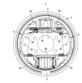
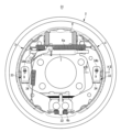
- FIG. 1 is a front view of a drum brake showing a first embodiment of the present invention
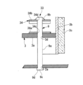
- 2 is a schematic cross-sectional view taken along line II-II of FIG. 1.
- FIG. 1 is a front view of a drum brake prior to assembling a hold-down mechanism to a back plate and a shoe web.
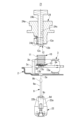
- 10 is an explanatory diagram showing a first step in the assembly method of the present invention for assembling a hold-down mechanism to a back plate and a shoe web.
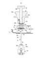
- FIG. FIG. FIG. FIG. 11 is an explanatory view showing the fourth step.
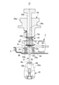
- FIG. 11 is an explanatory diagram showing the fifth step.
- FIG. 11 is an explanatory diagram showing the sixth step.
- FIG. 11 is an explanatory diagram showing the seventh step.
- FIG. 4 is a front view of a drum brake showing a second embodiment of the present invention.
- 12 is a schematic cross-sectional view taken along line XII-XII of FIG. 11.
- FIGS 1 and 2 show a first embodiment of the drum brake of the present invention.
- the drum brake 1 has a pair of arch-shaped brake shoes 3, 3 arranged on the inside of a back plate 2 fixed to the vehicle body, with one end of each of the brake shoes 3, 3 abutting against a piston 4a of a wheel cylinder 4 and the other end abutting against an electric actuator 5 for the parking brake.
- Shoe return springs 6a, 6b are stretched between the two brake shoes 3, 3 on the inside of the wheel cylinder 4 and the inside of the electric actuator 5, constantly biasing both brake shoes 3, 3 in the direction of contraction.
- an automatic brake gap adjustment device 7 is located on the center side of the back plate of the shoe return spring 6a on the wheel cylinder 4 side, which regulates the contraction position of the brake shoes 3, 3 outward, automatically adjusting the brake gap.
- Both brake shoes 3, 3 are formed by inverting the same shape, and are each made up of a shoe web 3a, 3a arranged parallel to the back plate 2, a rim 3b, 3b fixed in the cross direction to the outside of the shoe web 3a, 3a, and a lining 3c, 3c attached to the outer periphery of the rim 3b, 3b. Furthermore, hold-down mechanisms 8 are provided in two locations approximately in the middle of each shoe web 3a, 3a, and the brake shoes 3, 3 are attached to the back plate 2 via these four hold-down mechanisms 8.
- Each hold-down mechanism 8 is configured in the same way and is made up of an elastic member 10 and the hold-down pin 9 for attaching the elastic member 10 to the side of the shoe web 3a opposite the backplate.
- the elastic member 10 includes a coil spring 11 arranged on the side of the shoe web 3a opposite the backplate, a retainer 12 arranged on the opposite side of the coil spring 11 opposite the backplate, and a cup 13 interposed between the side of the shoe web 3a opposite the backplate and the coil spring 11 to position the coil spring 11.
- the back plate 2 is formed with four first insertion holes 2a through which the hold down pins 9 are inserted. Furthermore, each shoe web 3a, 3a is formed with two second insertion holes 3d through which the hold down pins 9 are inserted. Each first insertion hole 2a is formed so as to be positioned opposite the four second insertion holes 3d when the brake shoes 3, 3 are assembled to the back plate 2.
- the retainer 12 has a flange portion 12a that is placed on the top of the coil spring 11 (the side opposite the back plate) and a bowl-shaped insertion portion 12b that is inserted into the inner circumference of the coil spring 11, and a locking hole 12c formed as a long hole is formed in the center of the insertion portion 12b.
- the cup 13 has a cup-shaped mounting portion 13a on which the coil spring 11 is placed, a through hole 13b provided in the center of the mounting portion 13a through which the hold-down pin 9 is inserted, and an insertion piece 13c protruding from the periphery of the through hole 13b on the underside of the mounting portion 13a.
- the mounting portion 13a is formed with a diameter slightly larger than the outer diameter of the coil spring 11, and when the coil spring 11 is placed on the mounting portion 13a, the center of the through hole 13b coincides with the central axis of the coil spring 11.
- the hold-down pin 9 comprises a shaft portion 9a, a tip flat portion 9b (flat portion of the present invention) provided at the tip of the shaft portion 9a, and a base end locking portion 9c provided at the base end of the shaft portion 9a.
- the tip flat portion 9b is able to pass through the first insertion hole 2a, the second insertion hole 3d, the through hole 13b, and the locking hole 12c in the lengthwise direction, but has a thickness large enough to prevent it from passing through the locking hole 12c in the widthwise direction, and is formed in a roughly flattened semicircular shape.
- the base end locking portion 9c is formed with a diameter larger than the first insertion hole 2a, and is formed in a cone shape that gradually becomes larger in diameter toward the base end.
- the hold-down pin 9 thus formed has the base end locking portion 9c locked to the back plate 2, the shaft portion 9a inserted through the first insertion hole 2a, the second insertion hole 3d, and the through hole 13b, and the tip plate portion 9b inserted through the locking hole 12c, and the hold-down pin 9 is rotated to lock the tip plate portion 9b to the retainer 12.
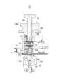
- the assembly device 21 is an assembly device for automatically assembling the hold-down mechanism 8 to the back plate 2 and the brake shoes 3, 3, and has an insertion means 22 that holds the base end locking portion 9c of the hold-down pin 9 and inserts the shaft portion 9a of the hold-down pin 9 into the first insertion hole 2a and the second insertion hole 3d, a positioning means 23 that holds the inserted shaft portion 9a and positions it at a predetermined position, and a rotation means 24 that rotates the hold-down pin 9 to assemble it.
- the insertion means 22 includes a clamp portion 22a having a pair of arms facing each other across an opening, and a support portion 22b that abuts against the base end surface 9d of the hold down pin 9 and supports the hold down pin 9.
- the positioning means 23 includes chuck portions 23a, 23a (Figs. 6 to 9) that are inserted between the back plate 2 and the shoe web 3a and hold the shaft portion 9a of the hold down pin 9.
- the rotating means 24 comprises a main body 24a and a rotating part 24b which is inserted into the main body 24a so as to be rotatable and movable up and down.
- the main body 24a comprises a through hole 24c which holds the rotating part 24b so as to be rotatable and movable up and down, and a holding part 24d which detachably holds the retainer 12 is provided on the outer periphery of the opening at the lower end side (shoe web side) of the through hole 24c.
- the rotating part 24b is formed in a cylindrical shape having an outer diameter which allows it to be inserted into the insertion part 12b of the retainer 12, and at its lower end (shoe web side end) it comprises an insertion groove 24e (Figs. 9 and 10) through which the tip flat part 9b of the hold down pin 9 is inserted.
- the operation of the insertion means 22, positioning means 23, and rotation means 24 is controlled by a control unit (not shown).
- the insertion piece 13c of the cup 13 is inserted into the second insertion hole 3d, and the mounting portion 13a of the cup 13 is placed on the side of the shoe web 3a opposite the backplate, and then the coil spring 11 is placed on the mounting portion 13a.
- the clamp portion 22a of the insertion means 22 clamps the outer periphery of the base end locking portion 9c of the hold down pin 9, and with the support portion 22b abutting against the base end surface 9d of the hold down pin 9, the insertion means 22 is moved to a position where the central axis of the hold down pin 9 coincides with the central axes of the first insertion hole 2a and the second insertion hole 3d.
- the flange portion 12a of the retainer 12 is held by the holding portion 24d of the rotating means 24, and the rotating means 24 is moved to a position where the central axis of the rotating portion 24b coincides with the central axis of the first insertion hole 2a and the second insertion hole 3d.
- the rotating means 24 is lowered toward the coil spring, and the flange portion 12a of the retainer 12 is brought into contact with the upper portion of the coil spring 11 (the side opposite the back plate).
- the positioning means 23 is inserted between the back plate 2 and the shoe web 3a while the chuck portions 23a, 23a are kept open.
- the chuck surfaces of the chuck portions 23a, 23a are positioned on the outer periphery side of the first insertion hole 2a and the second insertion hole 3d, respectively.
- the insertion means 22 is further raised, and the hold down pin 9 is inserted through the second insertion hole 3d, through hole 13b, and the inner circumference of the coil spring 11, with the tip flat portion 9b positioned near the locking hole 12c of the retainer 12 (insertion step of the present invention).
- the chuck portions 23a, 23a of the positioning means 23 are closed to hold the shaft portion 9a of the hold down pin 9 (positioning step of the present invention).
- the clamp portion 22a of the insertion means 22 is opened to release the hold on the hold down pin 9, and the hold down pin 9 is now supported by the support portion 22b.
- the retainer 12 held by the holding portion 24d of the rotating means 24 is released, and the rotating means 24 is moved upward to remove the tip plate portion 9b from the insertion groove 24e. Furthermore, the insertion means 22 is moved downward.
- the coil spring 11 of the hold-down mechanism 8 is assembled while still biasing the brake shoe 3 toward the back plate 2.
- the assembly device and assembly method of this embodiment can reliably prevent the hold-down pin from falling over during assembly by using the positioning means (chuck), improving ease of assembly.
- the hold-down pin can be easily and satisfactorily assembled by rotating the hold-down pin using the rotation means after releasing the hold of the hold-down pin by the insertion means and positioning means.
- the retainer 12 has a locking hole formed by a long hole, and the hold-down pin has a flat portion at its tip that can be inserted into the locking hole, thereby improving the insertion ability of the hold-down pin.
- the assembly of the hold-down mechanisms 8 can be done by assembling one each of the left and right brake shoes 3, 3 in the first step and the remaining two hold-down mechanisms 8 in the second step, but it is also possible to assemble four hold-down mechanisms 8 simultaneously, or to assemble two hold-down mechanisms 8 simultaneously to either the left or right brake shoe, and then assemble two hold-down mechanisms 8 simultaneously to the other brake shoe.
- FIGS. 11 and 12 show a drum brake 31 according to a second embodiment of the present invention. Components similar to those in the drum brake 1 according to the first embodiment are given the same reference numerals, and detailed descriptions thereof will be omitted.
- the elastic member 34 has a shoe web contact portion 34a that contacts the side of the shoe web 3a opposite the back plate, and a bent portion 34b.
- the shoe web contact portion 34a has a third insertion hole 34c through which the hold down pin 9 is inserted, and the bent portion 34b has an engagement hole 34d.
- the shoe hold pin 9 engages the base end engagement portion 9c with the back plate 2, the shaft portion 9a is inserted through the first insertion hole 2a, the second insertion hole 3d, and the third insertion hole 34c, and the tip flat portion 9b is inserted through the engagement hole 34d.
- the tip flat portion 9b is engaged with the bent piece 34b by rotating the hold down pin 9.
- the drum brake 31 of this embodiment also has the hold down mechanism 33 assembled using the assembly device 21 in a similar process.
- the assembly device and assembly method of the present invention are not limited to the drum brakes of the above-mentioned embodiments, but can be applied to any type of drum brake, such as those in which both ends of the brake shoes abut against the pistons of the wheel cylinders.
- insertion means 22a... clamping part, 22b... support part, 23... positioning means, 23a... chuck part, 24... rotation means, 24a... main body part, 24b... rotation part, 24c... through hole, 24d... holding part, 24e... insertion groove, 31... drum brake, 32... anchor member, 33... hold down mechanism, 34... elastic member, 34a... shoe web abutment part, 34b... bent part, 34c... third insertion hole, 34d... locking hole
Landscapes
- Engineering & Computer Science (AREA)
- General Engineering & Computer Science (AREA)
- Mechanical Engineering (AREA)
- Braking Arrangements (AREA)
Abstract
La présente invention concerne un dispositif d'assemblage pour un frein à tambour, un frein à tambour et un procédé d'assemblage pour un frein à tambour avec lequel il est possible d'assembler favorablement un élément élastique et une broche de maintien à une plaque arrière et à un segment de frein d'un frein à tambour par l'intermédiaire d'un assemblage automatique. Un dispositif d'assemblage (21) comprend : un moyen d'insertion (22) pour maintenir un côté d'extrémité de base d'une broche de maintien (9) et insérer la broche de maintien (9) dans un premier trou d'insertion (2a) formé dans une plaque arrière (2) et un second trou d'insertion (3d) formé dans une bande de segment (3a) ; et un moyen de positionnement (23) pour maintenir et positionner la broche de maintien (9) insérée. Le dispositif d'assemblage comprend en outre un moyen de rotation (24) qui, après que la broche de maintien (9) est positionnée par le moyen de positionnement (23), met en rotation la broche de maintien (9) dans un état dans lequel le maintien de la broche de maintien (9) par le moyen d'insertion (22) et le moyen de positionnement (23) est libéré, pour effectuer l'assemblage.
Priority Applications (1)
| Application Number | Priority Date | Filing Date | Title |
|---|---|---|---|
| JP2025521811A JP7876068B2 (ja) | 2023-05-19 | 2024-03-11 | ドラムブレーキの組付装置及びドラムブレーキ並びにドラムブレーキの組付方法 |
Applications Claiming Priority (2)
| Application Number | Priority Date | Filing Date | Title |
|---|---|---|---|
| JP2023082659 | 2023-05-19 | ||
| JP2023-082659 | 2023-05-19 |
Publications (1)
| Publication Number | Publication Date |
|---|---|
| WO2024241663A1 true WO2024241663A1 (fr) | 2024-11-28 |
Family
ID=93589315
Family Applications (1)
| Application Number | Title | Priority Date | Filing Date |
|---|---|---|---|
| PCT/JP2024/009291 Ceased WO2024241663A1 (fr) | 2023-05-19 | 2024-03-11 | Dispositif d'assemblage pour frein à tambour, frein à tambour, et procédé d'assemblage pour frein à tambour |
Country Status (2)
| Country | Link |
|---|---|
| JP (1) | JP7876068B2 (fr) |
| WO (1) | WO2024241663A1 (fr) |
Citations (5)
| Publication number | Priority date | Publication date | Assignee | Title |
|---|---|---|---|---|
| US3355791A (en) * | 1965-09-20 | 1967-12-05 | John H Castoe | Tool for brake shoe hold down springs |
| JPH09155760A (ja) * | 1995-12-04 | 1997-06-17 | Akebono Brake Ind Co Ltd | ホールドダウンカップ脱着工具 |
| JP2002130344A (ja) * | 2000-10-25 | 2002-05-09 | Nisshinbo Ind Inc | ドラムブレーキのブレーキシュー保持装置 |
| JP2020044951A (ja) * | 2018-09-18 | 2020-03-26 | 株式会社アドヴィックス | ドラムブレーキ |
| JP2020159400A (ja) * | 2019-03-25 | 2020-10-01 | 株式会社アドヴィックス | 車両用ブレーキ |
-
2024
- 2024-03-11 JP JP2025521811A patent/JP7876068B2/ja active Active
- 2024-03-11 WO PCT/JP2024/009291 patent/WO2024241663A1/fr not_active Ceased
Patent Citations (5)
| Publication number | Priority date | Publication date | Assignee | Title |
|---|---|---|---|---|
| US3355791A (en) * | 1965-09-20 | 1967-12-05 | John H Castoe | Tool for brake shoe hold down springs |
| JPH09155760A (ja) * | 1995-12-04 | 1997-06-17 | Akebono Brake Ind Co Ltd | ホールドダウンカップ脱着工具 |
| JP2002130344A (ja) * | 2000-10-25 | 2002-05-09 | Nisshinbo Ind Inc | ドラムブレーキのブレーキシュー保持装置 |
| JP2020044951A (ja) * | 2018-09-18 | 2020-03-26 | 株式会社アドヴィックス | ドラムブレーキ |
| JP2020159400A (ja) * | 2019-03-25 | 2020-10-01 | 株式会社アドヴィックス | 車両用ブレーキ |
Also Published As
| Publication number | Publication date |
|---|---|
| JPWO2024241663A1 (fr) | 2024-11-28 |
| JP7876068B2 (ja) | 2026-06-18 |
Similar Documents
| Publication | Publication Date | Title |
|---|---|---|
| US11078974B2 (en) | Disc brake for a commercial vehicle | |
| US6340076B1 (en) | Vehicular disk brake | |
| US12104665B2 (en) | Disc brake having an electromechanical actuator | |
| CN111480019B (zh) | 用于商用车的盘式制动器和制动衬面组 | |
| CN111527315A (zh) | 具有角度补偿功能的紧固装置 | |
| US20200040953A1 (en) | Brake assembly with brake pad carrier and clip | |
| CN1108465C (zh) | 局部加衬盘式制动器和用于它的制动器摩擦衬片 | |
| JPH07503301A (ja) | 保持ばねの回転が防止されたブレーキシュー | |
| JPS5825892B2 (ja) | デイスクブレ−キ | |
| JP4146288B2 (ja) | ドラムブレーキ装置 | |
| US6609594B1 (en) | Disc brake | |
| JP7578285B2 (ja) | 固定具、および固定装置 | |
| JP2013228011A (ja) | パーキングブレーキ機構および電動パーキングブレーキ | |
| US20200224740A1 (en) | Disc brake having an actuation device | |
| JP3844407B2 (ja) | ピンスライド型車両用ディスクブレーキのスライドピン取り付け構造 | |
| JP7829810B2 (ja) | ドラムブレーキの組付装置及びドラムブレーキの組付方法 | |
| JP4316433B2 (ja) | ディスクブレーキのパッド保持装置 | |
| JPH11247910A (ja) | ディスクブレーキ装置 | |
| US20160053639A1 (en) | Clamping nest having fixing elements | |
| CN115929819A (zh) | 包括定位装置的盘式制动器设备 | |
| JPH0630541U (ja) | 摩擦パッドのシム板取付け構造 | |
| JP3750824B2 (ja) | ケーブル式ドラムブレーキのケーブル接続装置及びケーブル接続に用いる治具 | |
| JPH0359288B2 (fr) | ||
| JP2007139053A (ja) | ドラムブレーキ装置及びその組立方法 | |
| US6651789B1 (en) | Limiter means for a release spring of a brake cable |
Legal Events
| Date | Code | Title | Description |
|---|---|---|---|
| 121 | Ep: the epo has been informed by wipo that ep was designated in this application |
Ref document number: 24810671 Country of ref document: EP Kind code of ref document: A1 |
|
| WWE | Wipo information: entry into national phase |
Ref document number: 2025521811 Country of ref document: JP |
|
| NENP | Non-entry into the national phase |
Ref country code: DE |
|
| 122 | Ep: pct application non-entry in european phase |
Ref document number: 24810671 Country of ref document: EP Kind code of ref document: A1 |