WO2024241580A1 - 産業機械の変化の対象区間選択装置及び対象区間選択方法 - Google Patents
産業機械の変化の対象区間選択装置及び対象区間選択方法 Download PDFInfo
- Publication number
- WO2024241580A1 WO2024241580A1 PCT/JP2023/019535 JP2023019535W WO2024241580A1 WO 2024241580 A1 WO2024241580 A1 WO 2024241580A1 JP 2023019535 W JP2023019535 W JP 2023019535W WO 2024241580 A1 WO2024241580 A1 WO 2024241580A1
- Authority
- WO
- WIPO (PCT)
- Prior art keywords
- unit
- section
- wear
- tool
- feature amount
- Prior art date
- Legal status (The legal status is an assumption and is not a legal conclusion. Google has not performed a legal analysis and makes no representation as to the accuracy of the status listed.)
- Ceased
Links
Images











Classifications
-
- B—PERFORMING OPERATIONS; TRANSPORTING
- B23—MACHINE TOOLS; METAL-WORKING NOT OTHERWISE PROVIDED FOR
- B23Q—DETAILS, COMPONENTS, OR ACCESSORIES FOR MACHINE TOOLS, e.g. ARRANGEMENTS FOR COPYING OR CONTROLLING; MACHINE TOOLS IN GENERAL CHARACTERISED BY THE CONSTRUCTION OF PARTICULAR DETAILS OR COMPONENTS; COMBINATIONS OR ASSOCIATIONS OF METAL-WORKING MACHINES, NOT DIRECTED TO A PARTICULAR RESULT
- B23Q17/00—Arrangements for observing, indicating or measuring on machine tools
- B23Q17/09—Arrangements for observing, indicating or measuring on machine tools for indicating or measuring cutting pressure or for determining cutting-tool condition, e.g. cutting ability, load on tool
-
- G—PHYSICS
- G05—CONTROLLING; REGULATING
- G05B—CONTROL OR REGULATING SYSTEMS IN GENERAL; FUNCTIONAL ELEMENTS OF SUCH SYSTEMS; MONITORING OR TESTING ARRANGEMENTS FOR SUCH SYSTEMS OR ELEMENTS
- G05B19/00—Program-control systems
- G05B19/02—Program-control systems electric
- G05B19/18—Numerical control [NC], i.e. automatically operating machines, in particular machine tools, e.g. in a manufacturing environment, so as to execute positioning, movement or co-ordinated operations by means of program data in numerical form
- G05B19/406—Numerical control [NC], i.e. automatically operating machines, in particular machine tools, e.g. in a manufacturing environment, so as to execute positioning, movement or co-ordinated operations by means of program data in numerical form characterised by monitoring or safety
- G05B19/4062—Monitoring servoloop, e.g. overload of servomotor, loss of feedback or reference
-
- G—PHYSICS
- G05—CONTROLLING; REGULATING
- G05B—CONTROL OR REGULATING SYSTEMS IN GENERAL; FUNCTIONAL ELEMENTS OF SUCH SYSTEMS; MONITORING OR TESTING ARRANGEMENTS FOR SUCH SYSTEMS OR ELEMENTS
- G05B19/00—Program-control systems
- G05B19/02—Program-control systems electric
- G05B19/18—Numerical control [NC], i.e. automatically operating machines, in particular machine tools, e.g. in a manufacturing environment, so as to execute positioning, movement or co-ordinated operations by means of program data in numerical form
- G05B19/406—Numerical control [NC], i.e. automatically operating machines, in particular machine tools, e.g. in a manufacturing environment, so as to execute positioning, movement or co-ordinated operations by means of program data in numerical form characterised by monitoring or safety
- G05B19/4063—Monitoring general control system
-
- G—PHYSICS
- G05—CONTROLLING; REGULATING
- G05B—CONTROL OR REGULATING SYSTEMS IN GENERAL; FUNCTIONAL ELEMENTS OF SUCH SYSTEMS; MONITORING OR TESTING ARRANGEMENTS FOR SUCH SYSTEMS OR ELEMENTS
- G05B19/00—Program-control systems
- G05B19/02—Program-control systems electric
- G05B19/18—Numerical control [NC], i.e. automatically operating machines, in particular machine tools, e.g. in a manufacturing environment, so as to execute positioning, movement or co-ordinated operations by means of program data in numerical form
- G05B19/406—Numerical control [NC], i.e. automatically operating machines, in particular machine tools, e.g. in a manufacturing environment, so as to execute positioning, movement or co-ordinated operations by means of program data in numerical form characterised by monitoring or safety
- G05B19/4065—Monitoring tool breakage, life or condition
Definitions
- This disclosure relates to a target section selection device and a target section selection method for changes in industrial machinery, and in particular to a target section selection device and a target section selection method for selecting a certain section from a plurality of fixed sections into which actual servo waveform data (time series data) in industrial machinery is divided, based on the tendency of fluctuations in feature quantities.
- Servo waveform data is the source data that can be used to infer the state of motors, machines, and processing. It can also be used to detect and predict failures and wear, so it is used in many places. Apparatuses for predicting tool wear and detecting tool deterioration conditions using servo waveform data are described in, for example, Japanese Patent Application Laid-Open No. 2003-233993 and Japanese Patent Application Laid-Open No. 2003-233994.
- Patent Document 1 describes a tool wear prediction device that can easily and accurately estimate the amount of tool wear. Specifically, Patent Document 1 describes a tool wear prediction device that predicts the amount of wear of a tool installed in a machine tool, and includes a tool wear prediction unit that calculates a predicted tool wear amount of the tool based on input machining data, and a tool wear correction processing unit that compares a value based on the machining data with a value based on data obtained from the machine tool and corrects the predicted tool wear amount based on the result of the comparison.
- Patent Document 2 describes a tool change timing management system including a data acquisition unit that acquires time series data indicating a machining state from a machine, a data extraction unit that extracts sample data from the time series data based on at least one condition or combination of conditions of machining, tool, workpiece, and tool speed, a machining state quantity calculation unit that calculates a machining state quantity which is a statistical index from the sample data, a tool deterioration status generation unit that generates tool deterioration status data in which the machining state quantities are arranged in time series, and a tool change timing calculation unit that calculates the tool change time based on the tool deterioration status data.
- FEM finite element method
- systems that estimate tool wear can estimate changes in wear based on actual cutting force data.
- systems that estimate tool wear due to the effects of noise and other factors, only a portion of the total machining can show tool wear, making it difficult to identify which points to extract and observe for fixed-point calculations.
- systems that estimate tool wear must exclude thin tools that are easily lost in noise, limiting the tools they can target.
- FEM finite element method
- a first representative aspect of the present disclosure includes a waveform division unit that divides servo waveform data into certain intervals; an NC program division unit that divides an NC program that drives an industrial machine into a certain number of blocks; a matching unit that performs matching between the servo waveform data for each fixed section divided by the waveform dividing unit and the NC program for each fixed block divided by the NC program dividing unit; a feature amount calculation unit that calculates a feature amount for each of the fixed intervals by using servo waveform data of the fixed interval; a target interval selection unit that selects a certain interval that can express the tendency of fluctuation in the feature amount from the plurality of divided certain intervals based on the tendency of fluctuation in the feature amount calculated by the feature amount calculation unit for each certain interval;
- the present invention relates to a device for selecting a target section of an industrial machine.
- a second representative aspect of the present disclosure is a method for implementing a method for implementing a computer-based method comprising: A process of dividing the servo waveform data into certain intervals; A process of dividing an NC program that drives an industrial machine into a certain number of blocks; A process of matching the servo waveform data for each of the divided fixed sections with an NC program for each of the divided fixed blocks; A process of calculating a feature amount for each of the fixed sections by using servo waveform data of the fixed section; selecting a certain section that can express the tendency of fluctuation in the feature amount from the plurality of divided certain sections based on the tendency of fluctuation in the feature amount calculated for each certain section; This is a method for selecting a target section for changes in industrial machinery.
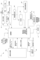
- FIG. 1 is a block diagram showing an overall configuration of a target section selection device that selects a section in which changes in an industrial machine are observed according to an embodiment of the present disclosure.
- 2 is a block diagram showing a target section selection configuration unit in the target section selection device of the present embodiment.
- FIG. FIG. 13 is a waveform diagram showing a certain section divided based on a change in the amount of movement of an X-axis position command.
- FIG. 11 is a diagram of an NC program showing certain blocks divided based on a change in the amount of movement of an X-axis position command.
- FIG. 13 is a diagram showing how matching is performed in the order of the same tool section, the same speed section and cutting feed signal section, and the section of change in the movement amount of the position command.
- FIG. 5A and 5B are diagrams showing an NC program, a waveform indicating the movement amount of an X-axis position command, and the slope of the waveform.
- FIG. 2 is a diagram showing a line of an NC program indicating a canned cycle and an NC program reproducing control without using the canned cycle.
- FIG. 13 is a diagram showing a process of calculating an average value of torque data in a certain section as a feature amount and calculating a transition graph of the feature amount.
- FIG. 11 is a diagram showing a method for selecting a selection target section candidate from a certain section.
- 11A and 11B are characteristic diagrams showing the variation in a feature amount and the variation in a slope, respectively, showing the tool replacement time.
- FIG. 13 is a diagram showing an example of a reference trend and a reference trend range.
- 2 is a block diagram showing a determination unit and a peripheral portion of the determination unit;
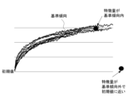
- FIG. 13 is a diagram showing a case where a feature amount is within a reference trend and a case where the feature amount is outside the reference trend.
- 13A and 13B are diagrams illustrating a case where a feature amount is within the reference trend and a case where the feature amount is outside the reference trend and close to an initial value of the reference trend.
- 2 is a block diagram showing a waveform generating unit and a peripheral unit of the waveform generating unit;
- FIG. 2 is a block diagram showing the configuration of a model representing a controller.
- FIG. 2 is a block diagram showing the configuration of a model of a spindle.
- FIG. 11 is a characteristic diagram showing changes over time in an actually measured torque value and an estimated torque value obtained by simulation using a cutting coefficient.
- FIG. 13 is a characteristic diagram showing the relationship between the average value of the estimated torque value and the cutting coefficient Ktc.
- FIG. 13 is a characteristic diagram showing the relationship between an average value of estimated torque values and a cutting coefficient Kte.
- FIG. 1 is a diagram showing the relationship between a characteristic diagram of cutting distance and friction amount, a characteristic diagram of wear amount and temperature, a characteristic diagram of temperature and friction speed, and a characteristic diagram of cutting distance and cutting resistance.
- FIG. 2 is an explanatory diagram showing a limit wear amount and a time when the limit wear amount is reached.
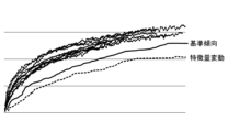
- FIG. 13 is a diagram showing how the reference tendency is changed when the fluctuation in the feature amount due to tool replacement changes;
- FIG. 13 is a diagram showing how the fluctuation in the amount of wear is changed and the reference tendency is changed when the limit amount of wear and the time when the limit amount of wear is reached are determined.
- FIG. 13 is an explanatory diagram showing an example in which the F value of an NC program is changed.
- 10 is a flowchart showing the operation of a target section selection configuration unit of the target section selection device.
- FIG. 1 is a block diagram showing the overall configuration of a target section selection device for selecting a section in which changes in an industrial machine are observed, according to an embodiment of the present disclosure.
- the target section selection device 10 includes a waveform division unit 101, an NC (Numerical Control) program division unit 102, a matching unit 103, a feature calculation unit 104, a target section selection unit 105, a judgment unit 106, a memory unit 107, a waveform generation unit 108, a parameter optimization unit 109, a wear estimation unit 110 and a display unit 111.
- the industrial machines for which the target section selection device 10 selects a section in which changes are to be observed are, for example, machine tools and cutting robots.
- the waveform division unit 101, the NC program division unit 102, the matching unit 103, the feature calculation unit 104, and the target section selection unit 105 are components (hereinafter, these components are referred to as "target section selection component") for realizing a function of selecting a certain section from a plurality of fixed sections into which the measured servo waveform data is divided, based on a tendency of fluctuation of a feature such as an average value of torque data.
- the memory unit 107 stores the measured servo waveform data used by the waveform division unit 101, and the NC program used by the NC program division unit 102 for controlling the machining operation of the industrial machine. The memory unit 107 will be described later.
- the memory unit 107 may be included in the target section selection component, but in the following description, the memory unit 107 is described as not being included in the target section selection component.
- the waveform generator 108 may utilize one or more external tools, and may be replaceable in the future if the waveforms generated are suitable and the time cost of generation is sufficiently fast.
- FIG. 2 is a block diagram showing a target section selection configuration unit in the target section selection device 10. As shown in FIG.
- the waveform division unit 101 reads out the measured servo waveform data acquired from the industrial machine from the storage unit 107, divides the measured servo waveform data into fixed intervals, outputs the divided servo waveform data to the feature calculation unit 104 or the matching unit 103, and stores it in the storage unit 107.
- the waveform division unit 101 also stores the divided fixed intervals as target intervals in the storage unit 107.
- the fixed intervals are intervals divided into units in which the X-axis, Y-axis, and Z-axis each perform one operation.
- the measured servo waveform data is, for example, a spindle speed, a spindle torque command, an X-axis position command, a Y-axis position command, a Z-axis position command, and a cutting feed signal.
- the fixed intervals for division are determined based on, for example, a change in the movement amount of the X-axis position command.
- the waveform division unit 101 may acquire the measured servo waveform data directly from the industrial machine without going through the storage unit 107, or may acquire the measured servo waveform data output from the industrial machine via a CNC (Computerized Numerical Control) or a PLC (Programmable Logic Controller).
- the measured servo waveform data stored in the storage unit 107 may also be data acquired directly from the industrial machine, or the measured servo waveform data output from the industrial machine may be data acquired via a CNC (Computerized Numerical Control) or a PLC (Programmable Logic Controller).
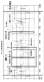
- Fig. 3 is a waveform diagram showing fixed sections divided based on the change in the movement amount of the X-axis position command.
- the same tool use section from one tool change operation to the next tool change operation the section with a constant cutting feed signal, and the section with a constant speed are also shown, but these sections are used for the matching operation in the matching unit 103 described later.
- the spindle speed, spindle torque command, Y-axis position command, Z-axis position command, and cutting feed signal are also shown.
- the vertical axis scales a1 to a9 are -20000, -15000, -10000, -5000, 0, 5000, 10000, 15000, and 20000 (1/mm).
- the vertical axis scales a1 to a9 are -200, -150, -100, -50, 0, 50, 0, 100, 150, and 200 (%).
- the vertical axis scales a1 to a9 are -300, -200, -100, 0, 100, 200, 300, 400, and 500 (mm).
- the vertical axis scales a1 to a9 are -200, -100, 0, 100, 200, 300, 400, 500, and 600 (mm).
- the vertical axis scales a1 to a9 are -300, -200, -100, 0, 100, 200, 300, 400, and 500 (mm).
- the vertical axis scales a1 to a9 are -200, 0, 200, 400, 600, 800, 1000, 1200, and 1400.
- NC program dividing unit 102 The NC program dividing unit 102 reads out an NC program for controlling the machining operation of the industrial machine from the storage unit 107, divides the NC program into fixed blocks, outputs the divided NC program to the matching unit 103, and stores it in the storage unit 107.
- the fixed blocks are determined based on a change in the amount of movement of the X-axis position command.
- FIG. 4 is a diagram of an NC program showing fixed blocks divided based on changes in the amount of movement of the X-axis position command.
- FIG. 4 also shows fixed blocks corresponding to the same tool use section from one tool change operation to the next tool change operation, fixed blocks corresponding to a section where the cutting feed signal is constant, and fixed blocks corresponding to a section where the speed is constant, and these fixed blocks are used for the matching operation in matching unit 103, which will be described later.
- the matching unit 103 matches (associates) the servo waveform data for each fixed section divided by the waveform dividing unit 101 with the NC program for each fixed block divided by the NC program dividing unit 102, outputs the servo waveform data for each fixed section to the matching unit 103, and stores the correspondence in the storage unit 107.
- the reason for associating the behavior of the actual machine with the NC program is to confirm which part of the NC program has behavior that should be noted when analyzing the actual machine.
- the matching unit 103 performs matching in multiple stages between the fixed section set in the waveform division unit 101 and the fixed block set in the NC program division unit 102 for the change in the amount of movement of the position command, since it is difficult to perform matching immediately. Specifically, the matching unit 103 performs matching between the fixed section and the fixed block in the following order: matching of the same tool section, matching of at least one section of the same speed section and the cutting feed signal section, and matching of the section of the change in the amount of movement of the position command.
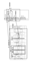
- Figure 5 shows how matching is performed in the order of the same tool section, the same speed section and the cutting feed signal section, and the section of the change in the amount of movement of the position command.
- FIG. 6 is a diagram showing an NC program, a waveform indicating the amount of movement of the position command on the X-axis, and the slope of the waveform.
- the NC program indicated by G01 X20.0 and G01 X10.0 can be decomposed into two parts, G01 X20.0 and G01 X10.0, but the waveforms indicating the movement amount of the X-axis position command corresponding to this NC program have the same slope, making it difficult to separate them.
- the NC program and waveform data indicated by G01 X20.0 and G01 X10.0 are not separated, but are treated as an NC program and waveform data indicating a single movement amount.
- Fig. 7 is a diagram showing one line of an NC program indicating a canned cycle and an NC program that reproduces control without using a canned cycle.
- the feature amount calculation unit 104 calculates the feature amount for a certain interval by using the servo waveform data for each certain interval that is output from the waveform division unit 101 or that is found to match with the NC program by the matching unit 103.
- the feature amount for a certain interval is, for example, at least one of statistics of torque data such as the mean, variance, skewness, kurtosis, and RMS (root mean square) of the torque data (for example, spindle torque command) for the certain interval.
- the feature amount calculation unit 104 calculates, as a feature amount, an average value of torque data in a fixed interval R1 (shown as "interval R1" in Fig.
- Fig. 8 is a diagram showing the process of calculating the average value of torque data in the fixed intervals as a feature amount and calculating the transition graph of the feature amount.
- the target interval selection unit 105 selects a certain interval that can express the tendency of the fluctuation of the feature amount from the divided plurality of certain intervals based on the tendency of the fluctuation of the feature amount calculated by the feature amount calculation unit 104 for each certain interval.
- the method of selecting a fixed section is, for example, as shown in Fig. 9, to calculate the slope of a curve showing the variation in the feature quantity as the tendency of variation in the feature quantity of fixed sections R1 and R2, and if a continuous upward trend in the slope is recognized as in fixed section R2, the fixed section is selected as a candidate section to be selected. As shown in Fig.
- the trend calculation unit 1051 calculates the change in slope based on the change in the feature amount. Specifically, the trend calculation unit 1051 smoothes the feature amount using a moving average or the like, and calculates the difference between a value at a given time and the previous value as the slope (trend) of the change in the feature amount.
- the section selection unit 1052 calculates the slope of the curve showing the variation of the feature quantity as the calculated variation trend, and if a continuous upward trend in the slope is observed, selects it as a candidate section to be selected, and if a continuous upward trend in the slope is not observed, excludes it from the candidates to be selected.
- a continuous upward trend in the slope may represent tool wear, for example.
- the replacement calculation unit 1053 determines the time when the feature value drops sharply and the slope becomes negative in the section selected as the candidate section to be selected as the time to replace the tool, and stores this in the storage unit 107. For example, as shown in FIG. 10, the time when a sharp drop is observed in the characteristic diagram showing the variation in the feature value of a certain section R2 and/or the characteristic diagram showing the variation in the slope is determined as the time to replace the tool.
- the reference trend calculation unit 1054 creates a reference trend by superimposing and averaging one or more fluctuations in the feature values between tool changes, as shown in FIG. 10, for example, and stores the reference trend in the storage unit 107.
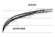
- the reference trend range uses the maximum value (MAX), minimum value (MIN), or standard deviation of the multiple reference trends.
- FIG. 11 is a diagram showing an example of a reference trend and a reference trend range.
- the target section selection device 10 includes a determination unit 106, a memory unit 107, a waveform generation unit 108, a parameter optimization unit 109, a wear estimation unit 110, and a display unit 111.
- the determination unit 106, the memory unit 107, the waveform generation unit 108, the parameter optimization unit 109, the wear estimation unit 110, and the display unit 111 will be described below.
- Some or all of the determination unit 106, the memory unit 107, the waveform generation unit 108, the parameter optimization unit 109, the wear estimation unit 110, and the display unit 111 may be provided outside the target section selection device 10.
- FIG. 12 is a block diagram showing the determination unit 106 and the surrounding area of the determination unit 106.
- the determination unit 106 determines the degree of deviation from the reference and determines whether or not to replace a tool, based on the feature amount for a certain interval output from the feature amount calculation unit 104.
- the feature amount for a certain interval is, for example, at least one of statistics of the torque data, such as the mean, variance, skewness, kurtosis, and RMS (root mean square) of the torque data for the certain interval.
- the judgment unit 106 includes a reference judgment unit 1061 and a replacement judgment unit 1062 .
- the reference determination unit 1061 determines how far the feature calculated by the feature calculation unit 104 for actual servo waveform data newly acquired from an industrial machine is from the reference trend calculated by the reference tendency calculation unit 1054 and read out from the storage unit 107.
- Fig. 13 is a diagram showing a case where the feature is within the reference tendency and a case where it is outside the reference tendency.
- the reference judgment unit 1061 judges that the tool is broken when the features calculated by the feature calculation unit 104 for the actual servo waveform data newly acquired from the industrial machine match with the features calculated by the feature calculation unit for the estimated servo waveform data generated by the waveform generation unit 108 in a no-load state (a state in which no workpiece is present).
- the replacement determination unit 1062 determines whether the feature amount calculated by the feature amount calculation unit 104 is data before or after the tool replacement time calculated by the replacement calculation unit 1053.
- the replacement determination unit 1062 determines that the tool is before replacement if the feature amount is within the reference trend, and determines that the tool is after replacement if a sudden change has occurred and the feature amount is outside the reference trend and close to the initial value of the reference trend, as shown in Fig. 14.
- Fig. 14 is a diagram showing a case where the feature amount is within the reference trend and a case where the feature amount is outside the reference trend and close to the initial value of the reference trend.
- the memory unit 107 stores measured servo waveform data obtained from the industrial machine and used by the NC program division unit 102, and an NC program that controls the machining operation of the industrial machine and is used by the matching unit 103.
- the memory unit 107 also inputs and stores machine data, CNC (Computerized Numerical Control) parameters, macro variables, workpiece origin offset, tool offset values, etc.
- the memory unit 107 also inputs and stores servo waveform data such as cutting distance, cutting coefficient, estimated cutting force, estimated wear amount, cutting tool temperature, torque command, etc., as well as digitized shape and contact length of the workpiece (work), and tool information.
- the shape and contact length of the workpiece (work), and tool information are characteristic values indicating at least one characteristic of the workpiece and the tool.
- the storage unit 107 also stores servo waveform data of the estimated cutting force and servo waveform data of the estimated wear amount.
- the memory unit 107 also stores the correspondence between the behavior of the actual machine and the NC program, the degree of tendency, the target section, the reference tendency, the tool change date and time, and the machining time (cycle time).
- the waveform generating unit 108 generates servo waveform data from the NC program divided by the NC program dividing unit 102 . Furthermore, the waveform generating unit 108 sets execution parameters and executes a simulation to generate waveform data (estimated cutting force, estimated torque, etc.).
- the simulation execution parameters are motor characteristics, tool information, workpiece (material) information, cutting coefficients, etc. Most of the parameters are determined once the motor, tool, material, etc. are determined. However, the parameters used to estimate the cutting force are The cutting coefficients (Kte, Ktc) which are the execution parameters are obtained so as to match the actually measured torque by performing a simulation multiple times in a parameter optimization unit 109 described later.
- the torque command (TCMD) is calculated from the cutting coefficients as follows: However, since the cutting coefficients cannot be obtained directly from the torque command, the cutting coefficients (Kte, Ktc) are obtained by executing a simulation in the parameter optimization unit 109.
- FIG. 15 is a block diagram showing the waveform generating section 108 and the peripheral parts of the waveform generating section 108.
- the waveform generating unit 108 includes an NC program interpreting unit 1081 , a command generating unit 1082 , a feedback control unit 1083 , and a cutting force estimating unit 1084 .
- NC program interpretation unit 1081 determines the travel distance, travel path, and command speed based on input information such as divided NC (Numerical Control) programs (which become machining programs) output from the storage unit 107, CNC (Computerized Numerical Control) parameters, macro variables, workpiece origin offsets, tool offset values, etc.
- NC program interpretation unit 1081 interprets the NC program that specifies the operation of positioning the feed axis and speed control of the spindle, breaks down the NC program into each code and value, and determines the travel distance, travel path, and command speed.
- the NC program interpretation unit 1081 performs, for example, the following interpretations (A), (B), (C), and (D).
- (A) Codes M03, M04, and M05 are converted to clockwise rotation of the spindle, counterclockwise rotation of the spindle, and stop of spindle rotation.
- the command generating unit 1082 generates interpolation data by performing an interpolation calculation of points on the movement path at an interpolation period based on the movement distance, the movement path such as a straight line or a circular arc, and the command speed obtained by the NC program interpreting unit 1081. Based on the interpolated data, an acceleration/deceleration profile is generated, and then distributed to each control axis, so that a position command value or Give a speed command value.
- the command generating unit 1082 performs the following operations (E), (F), (G), (H), and (I).
- E Calculate the distance traveled.
- F Create a speed and position profile at the tool tip to satisfy the travel distance, command speed, and acceleration/deceleration parameters set by the machine. At this time, it is possible to consider the travel path and add a constraint such as keeping the acceleration in the centripetal direction of the arc below a certain level.
- G The profile is discretized for each control period. In the previous stage, the speed and position profiles are generated as a function of continuous time, and by sampling from them, the processing of fractions less than the control period can be omitted.
- acceleration/deceleration and filtering described above are the same ideas for command generation as in actual numerical control devices.
- CAM software did not handle acceleration/deceleration or filtering, and instead simulated movement at the command speed.
- cutting simulations have never taken into account feed including acceleration/deceleration, but by simulating elements such as acceleration/deceleration and filtering, it is possible to calculate required time and cycle time that are close to the actual time, which is useful when comparing with data from the actual machine.
- the feedback control unit 1083 simulates feedback control for making the drive of the motors that drive the feed axis and the main axis follow the position command value or speed command value generated by the command generation unit 1082, and generates and outputs servo waveform data.
- a feed axis is a mechanism that controls the relative positional relationship between a workpiece and a tool in industrial machinery.
- feed axes There are two types of feed axes: linear axes that perform linear translational motion, and rotary axes that perform rotary motion.
- linear axes that perform linear translational motion
- rotary axes that perform rotary motion.
- two models are required: a model representing the feed axis and a model of the controller that controls it.
- the feed axis converts the rotational motion of the motor into translational motion through a conversion mechanism such as a ball screw.
- the rotation angle of the motor is represented as ⁇
- the displacement in the translational motion after passing through the conversion mechanism is represented as X.
- the torque applied to the motor is represented as T.
- the feed axis is considered to be a rigid body, and its motion is represented by Equation 1 (Equation 1 below).
- Equation 1 J represents the moment of inertia of the drive mechanism, and D represents the viscous friction coefficient.
- Equation 1 When the rotation angle ⁇ in Equation 1 is replaced with the rotation speed ⁇ , Equation 1 can be expressed as Equation 2 (hereinafter, Equation 2).
- Equation 3 Equation 3 below
- Equation 3 corresponds to a first-order lag low-pass filter.
- FIG. 16 is a block diagram showing the configuration of a model representing a controller.
- the controller shown in FIG. 16 converts a position command XC in the X-axis direction into a rotation angle to obtain a position command ⁇ cmd , calculates the difference with the position feedback ⁇ fd to generate a speed command ⁇ cmd , calculates the difference with the speed feedback ⁇ fd , and performs PI processing.
- the controller integrates the signal after the PI processing to generate a torque command T cmd , and sets the detected angular velocity output from the feed axis model as the speed feedback ⁇ fd .
- the detected angular velocity is integrated to obtain a detected angle to be used as position feedback.
- the transfer function representation of the configuration shown in FIG. 16 is in the continuous time domain.
- a numerical simulation on a computer is performed in the discrete time domain, it is necessary to convert the transfer function shown in the continuous time domain into the discrete domain. This will be done according to the following rules.
- ⁇ Blocks involving simple addition or constant multiplication are calculated by simply adding variables and multiplying them by constants.
- the integral term 1/s is calculated by numerical integration, that is, for the time span t of the discrete simulation and the time series x of the input, the output is calculated using Equation 4 (Equation 4 below).
- the first-order term 1/(1+s) corresponds to a low-pass filter. This is calculated by forward difference.
- Equation 5 the conversion equation shown in Equation 5 (hereinafter Equation 5) is used.
- the spindle is the motor shaft for rotating the tool. It is the same as the feed axis in that it drives the motor and controls the machine end, but unlike the feed axis, it transmits rotational motion directly at the machine end instead of translational motion. Therefore, the spindle does not have a conversion mechanism using a ball screw. Also, unlike the feed axis, the input to the spindle is a speed command, and the internal control only has a speed control loop. Here, IP control is used.
- FIG. 17 is a block diagram showing the configuration of a model of a spindle.
- the feedback control unit 1083 outputs a torque command, which becomes servo data created within the feedback control unit 1083, to the cutting force estimation unit 1084.
- the cutting force estimation unit 1084 estimates the cutting force of the cutting tool based on the torque command output from the feedback control unit 1083 and the characteristic value stored in the storage unit 107.
- the value is a quantified workpiece shape or contact length.
- the cutting force is the resistance of the material to the penetration of the cutting tool, and means the force required to continue cutting.
- Torque [N.m] is calculated by multiplying the cutting force by the (principal force [N]) x (radius [ m]), so cutting force can be used almost synonymously with torque.
- the estimated cutting force can be calculated using the instantaneous cutting force model described below.
- the cutting edge of the cutting tool is cut into minute pieces in the vertical direction.
- the vertical size of the microblade is dz.
- the cutting forces acting on the microblade when the cutting tool cuts the workpiece are defined as dFt for the force in the tangential direction of the tool, dFr for the force in the radial direction, and dFa for the force in the axial direction.
- h is defined as the length of the workpiece cut by the microblade in one rotation (called the cutting thickness). The cutting thickness h depends on the position z and the rotation angle ⁇ of the microblade.
- the instantaneous cutting model is one in which the relationship of Equation 7 (hereinafter Equation 7) is established.
- the cutting coefficients Kte, Ktc, Kre, Krc, Kae, and Kac are coefficients determined by the physical relationship between the tool and the workpiece.
- the cutting coefficients Ktc, Krc, and Kac are coefficients equivalent to the specific cutting resistance.
- the cutting force can be calculated by somehow numerically representing the shape of the workpiece on a computer and simulating the cutting process at discrete times.
- a grid space divided in the X and Y directions is considered, and the workpiece shape is numerically expressed by recording the height of the workpiece in each cell.
- the cutting tool is expressed as a small plate divided in the height direction. The positions of the cutting tool and workpiece are updated every small time, the height of the workpiece cell that the tool comes into contact with is reduced, and a cutting force is generated according to the cutting thickness that occurs in that part, to perform the simulation.
- Equation 8 the cutting torque dT applied to the microplate of the cutting tool is given by the following Equation 8 (Equation 8 below).
- the cutting torque dT depends on the position z and the rotation angle ⁇ of the tool microplate.
- the average value h′ of the cutting thickness h is set as shown in the following formula 9 (the following formula 9).
- Equation 10 the sum of the tool height in contact with the workpiece is set as Cz.
- Cz will be called the contact length.
- the average cutting thickness h' is found from the machining conditions of feed rate and rotation speed. If the specific cutting resistance has been determined, the cutting torque can be simulated by finding the contact length Cz at each position. In reality, if measurement data is available, the contact length at each position (which serves as basic cutting data) can be found from Equation 10. The same applies to cutting forces in directions other than the tangential direction.
- the parameter optimization unit 109 optimizes the execution parameters so that the fluctuation of the feature amount in the fixed section selected by the target section selection unit 105 coincides with the fluctuation of the feature amount determined from the cutting force estimated from the servo waveform data generated by the waveform generation unit 108.
- the cutting coefficients (Kte, Ktc) serving as execution parameters used in the cutting force estimation unit 1084 are determined by executing a simulation in the parameter optimization unit 109.
- the parameter optimization unit 109 optimizes the cutting coefficients (Kte, Ktc), which are execution parameters, so that the average value of the measured torque, which is a characteristic quantity, in a certain section, coincides with the average value of the estimated torque, which is a characteristic quantity obtained from the cutting force.
- the first method is to optimize the cutting coefficients (Kte, Ktc) that match the actual measured torque at a certain point in time by determining the cutting coefficients Ktc and Kte so that the estimated torque average generated by changing the cutting coefficients Ktc and Kte is approximately the same as the characteristic value (average) of the actual measured torque.
- the characteristics of the measured torque value and the estimated torque value obtained by simulation using the cutting coefficients are shown in Fig. 18.
- the vertical axis represents the torque value and the horizontal axis represents the time.
- the point where Ktc and Kte are adjusted in the torque is fixed.
- the average value of the estimated torque values and the cutting coefficient Ktc are proportional to each other as shown in the characteristic diagram of Fig. 19, and the cutting coefficient Ktc is calculated so that the average value of the estimated torque values coincides with the average value of the actually measured torque values.
- the average value of the estimated torque values and the cutting coefficient Kte are proportional to each other as shown in the characteristic diagram of Fig. 20, and the cutting coefficient Kte is calculated so that the average value of the estimated torque values coincides with the average value of the actually measured torque values.
- the cutting coefficient is calculated from the change in the actually measured torque, and the formula for the change in the cutting coefficient is optimized.
- the average measured torque (cutting force) changes due to wear, etc. It is possible to obtain the execution parameter (cutting coefficient) to generate an estimated waveform that matches the change.
- the equation for the change in the cutting coefficient is fitted to a certain equation, as the torque changes in accordance with wear, and the cutting coefficient also changes. To find this equation, the initial cutting coefficient value and the coefficient of change are required, and the initial cutting coefficient value is calculated using the measured torque value immediately after the tool is replaced, resulting in the cutting coefficient value Ktc.
- the equation for the change is calculated by using the equations of multiple actual measurements to find the cutting coefficient value Ktc at each point.
- the changes in these cutting coefficient values are calculated using an approximation equation. This is the equation for the change in the cutting coefficient.
- the tool is replaced several times, and the changes in the cutting coefficient for the multiple times are added together to obtain an equation for the change in the standardized cutting coefficient (average, etc., is also acceptable).
- the wear estimation unit 110 estimates the amount of wear of a tool based on the cutting distance and wear rate of the tool.
- the wear estimation unit 110 estimates the wear of the cutting tool based on the fluctuation of the characteristic values stored in the memory unit 107 .
- the wear of cutting tools occurs on the cutting edge due to friction with the workpiece and chips.
- the wear of a cutting tool can be divided into wear on the rake face and wear on the flank face. Unless the cutting speed is high, wear on the flank face is predominant.
- the wear rate of flank wear dW/dL can be calculated by the following formula 11 (Equation 11 below).
- W is the wear rate of flank wear
- L is the cutting distance.
- K is a coefficient determined by the shape of the agglomerated particles
- H is the hardness of the cutting tool side
- ⁇ t is the normal stress on the wear surface.
- the normal stress on the wear surface ⁇ t is calculated by substituting the cutting speed and the tool clearance angle.
- the wear rate of the rake wear can be calculated by the following formula 12 (Equation 12 below): where W is the amount of flank wear, L is the cutting distance, C and ⁇ are characteristic constants determined by the combination of the cutting tool and the workpiece, and T is the temperature of the cutting tool.
- the cutting distance L and the temperature T of the cutting tool in the above formulas 11 and 12 are characteristic values stored in the storage unit 107.
- the cutting temperature can be estimated from the cutting speed.
- the estimated wear amount per machining is calculated from the wear rate and the cutting distance, which is the distance cut when the tool is used.
- the estimated wear amount of the tool can be calculated by executing one machining operation, not directly from the torque value (variation of the feature value).
- the variation of the estimated wear amount since the tool change is the sum of the wear amounts since the tool change.
- characteristic diagram A shows the relationship between cutting distance (unit: m) and friction amount (unit: ⁇ m)
- characteristic diagram B a characteristic diagram showing the relationship between wear amount (unit: ⁇ m) and temperature (unit: K)
- characteristic diagram C a characteristic diagram showing the relationship between temperature (unit: K) and friction speed (unit: ⁇ m/m)
- characteristic diagram D a characteristic diagram showing the relationship between cutting distance (unit: m) and cutting resistance (unit: Nm/m)
- the wear estimation unit 110 estimates the limit wear amount of the cutting tool and the time when the limit wear amount will be reached.
- the limit wear amount W lim can be calculated using Formula 11 or Formula 12 by setting the limit cutting distance L lim .
- the limit cutting distance Lmin is not a set life but a cutting distance that can be used up to the limit, and since it changes depending on the required machining accuracy, an appropriate value is entered.
- the time when the limit wear amount is reached is the same as the time when the limit cutting distance L lim is reached.
- the time t lim when the limit cutting distance L lim is reached can be estimated by the following formula 13 (the following formula 13) if the cycle time t ct required for one NC program execution is known and the cutting distance L 1 per cycle time is known.
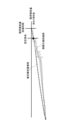
- Fig. 22 is an explanatory diagram showing the limit wear amount and the time when the limit wear amount is reached.
- Fig. 22 shows the transition of the estimated wear amount and the transition of the wear amount at the actual cutting force, and also shows the limit wear amount and the time when the limit wear amount is reached.
- the target section selection unit 105 recalculates and updates the reference trend
- the parameter optimization unit 109 recalculates and updates execution parameters such as the cutting coefficient
- the wear estimation unit 110 recalculates and updates the fluctuation in the wear amount and the limit wear amount.
- the display unit 111 displays the variation in the feature amount for each fixed interval and the variation in the amount of wear of the tool corresponding to the interval. In addition, the display unit 111 displays on the display screen the fluctuation in the amount of wear of the tool corresponding to a certain section calculated by the wear estimation unit 110, the limit wear amount of the tool, and the time when the limit wear amount will be reached.
- the variation in the amount of wear of the tool, the limit wear amount of the cutting tool, and the time when the limit wear amount is reached may be shown numerically or may be graphed as shown in FIG.
- the display unit 111 displays on the display screen the cycle time of the NC program estimated based on the number of calculations required by the command generating unit 1082 for the interpolation calculation of the NC program,
- the NC program stored in the storage unit 107 is edited so as to satisfy the target cycle time. If we have a time series of cutting force, we can determine the cycle time of the target time series.
- the cycle time can be calculated by counting the time of the servo data. In the case of actual measurement, the cycle time for the NC program of the actual machine is known, and in the case of estimation, the cycle time for the NC program executed on this device is known. If you change part of the NC program (for example, F value, tool path change, etc.), the cycle time will change.
- Fig. 25 is an explanatory diagram showing an example in which the F-value of an NC program is changed.
- the F-value in the NC program before editing is shown as F800, but in the NC program after editing, the F-value is shown as F1000.
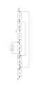
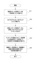
- FIG. 26 is a flowchart showing the operation of the target section selection configuration unit of the target section selection device.
- the waveform dividing section 101 reads out the actually measured servo waveform data from the storage section 107, divides the actually measured servo waveform data into certain intervals, and outputs the divided servo waveform data.
- step S12 the NC program division unit 102 reads out from the memory unit 107 an NC program that controls the machining operation of the industrial machine, divides the NC program into a certain number of blocks, and outputs the divided NC program.
- Step S12 may be executed before step S11, or may be executed in parallel with step S11.
- step S13 the matching unit 103 matches the servo waveform data for each fixed section divided by the waveform division unit 101 with the NC program for each fixed block divided by the NC program division unit 102.
- step S14 the feature calculation unit 104 calculates the feature for a certain section using the servo waveform data for each certain section that has been found to match the NC program by the matching unit 103.
- step S15 the target interval selection unit 105 calculates the trend of the variation of the feature calculated by the feature calculation unit 104, and selects a fixed interval that can express the trend of the variation of the feature from among the multiple fixed intervals based on the calculated trend.
- the target section selection device can be realized by hardware, software, or a combination of these.
- being realized by software means being realized by a computer reading and executing a program.
- each target section selection device is equipped with a calculation processing device such as a CPU (Central Processing Unit).
- the target section selection device also has a secondary storage device such as an HDD (Hard Disk Drive) that stores various control programs such as application software or an OS (Operating System), and a main storage device such as a RAM (Random Access Memory) for storing data temporarily required for the calculation processing device to execute a program.
- a calculation processing device such as a CPU (Central Processing Unit).
- the target section selection device also has a secondary storage device such as an HDD (Hard Disk Drive) that stores various control programs such as application software or an OS (Operating System), and a main storage device such as a RAM (Random Access Memory) for storing data temporarily required for the calculation processing device to execute a program.
- HDD Hard Disk Drive
- OS Operating System
- main storage device such as a RAM (Random Access Memory) for storing data temporarily required for the calculation processing device to execute a program.
- the arithmetic processing unit reads the application software or OS from the auxiliary storage device, and while expanding the loaded application software or OS into the main storage device, performs arithmetic processing based on the application software or OS. Also, based on the results of this calculation, various pieces of hardware equipped in each device are controlled. In this way, the functional blocks of this embodiment are realized.
- Each component included in the target section selection device can be realized by hardware including electronic circuits, etc.
- some or all of the functions of each component included in the target section selection device can be configured from integrated circuits (ICs), such as ASICs (Application Specific Integrated Circuits), gate arrays, FPGAs (Field Programmable Gate Arrays), and CPLDs (Complex Programmable Logic Devices).
- ICs integrated circuits
- ASICs Application Specific Integrated Circuits
- FPGAs Field Programmable Gate Arrays
- CPLDs Complex Programmable Logic Devices
- Non-transitory computer readable media include various types of tangible storage media.
- Examples of non-transitory computer readable media include magnetic recording media (e.g., hard disk drives), magneto-optical recording media (e.g., magneto-optical disks), CD-ROM (Read Only Memory), CD-R, CD-R/W, and semiconductor memory (e.g., mask ROM, PROM (Programmable ROM), EPROM (Erasable PROM), flash ROM, and RAM (random access memory)).
- the program may also be provided to the computer by various types of transitory computer readable media.
- the following effects can be obtained.
- Matching enables you to determine which parts of a program are likely to have errors.
- sensors are not required and retrofitting is easy.
- the correlation between the waveform data and the amount of wear is simulated. Since it is only necessary to reproduce the waveform data, there is no need to obtain highly accurate physical quantities, making prior experiments unnecessary.
- Abnormalities (wear) can be reproduced.
- the range for calculating the amount of wear can be narrowed down based on actual data.
- the interval to be simulated can be minimized.
- a certain section can be selected from a number of fixed sections into which the actually measured servo waveform data of the industrial machinery is divided, based on the tendency of fluctuations in the feature quantity.
- a feature amount calculation unit (104) that calculates a feature amount for each of the fixed intervals by using servo waveform data for the fixed intervals;
- the device for selecting a target section of an industrial machine change is provided.
- Appendix 2 The device for selecting a target section for changes in an industrial machine as described in Appendix 1, wherein the feature amount is a statistical amount of torque data within the certain section.
- the target section selection unit (105) a tendency calculation unit (1051) that calculates a change in slope based on the change in the feature amount calculated by the feature amount calculation unit; a section selection unit (1052) that selects a certain section representing wear from the change in the slope calculated by the tendency calculation unit; a tool replacement calculation unit (1053) that calculates a tool replacement time from at least one of a feature amount variation and a slope variation in the fixed section selected by the section selection unit; a reference trend calculation unit (1054) that calculates a reference trend from a variation in one or more feature values between tool replacement times calculated by the replacement calculation unit; 2.
- a device for selecting a target section of a change in an industrial machine comprising:
- (Appendix 4) a waveform generating unit (108) that generates servo waveform data from the NC program divided by the NC program dividing unit; a parameter optimization unit (109) that optimizes execution parameters so that a variation in a feature value in the fixed section selected by the target section selection unit coincides with a variation in a feature value determined from a cutting force estimated from the servo waveform data generated by the waveform generation unit; a determination unit (106) for determining whether a tool has been replaced and for determining a deviation of the feature from a reference; a wear estimation unit (110) that estimates a wear amount of the tool based on a cutting distance and a wear rate of the tool; A display unit (111) that displays the variation in the feature amount for each fixed section and the variation in the wear amount of the tool corresponding to the fixed section;
- the target section selection unit (105) a tendency calculation unit (1051) that calculates a change in slope based on the change in the feature amount calculated by the feature amount calculation unit; a section selection unit (1052) that selects a certain section representing wear from the change in the slope calculated by the tendency calculation unit; a tool replacement calculation unit (1053) that calculates a tool replacement time based on a feature amount variation and a slope variation in the fixed section selected by the section selection unit; a reference trend calculation unit (1054) that calculates a reference trend from a variation in one or more feature values between tool replacement times calculated by the replacement calculation unit,
- the determination unit (106) a reference determination unit (1061) that determines whether a feature calculated by the feature calculation unit for actual servo waveform data newly acquired from the industrial machine is different from the reference tendency calculated by the reference tendency calculation unit; a replacement determination unit (1062) that determines whether the feature amount calculated by the replacement calculation unit is data before or after the calculated tool replacement time;
- a memory unit (107) is provided for storing a characteristic value indicating at least one characteristic of a workpiece and a tool;
- the waveform generating unit (108) An NC program interpretation unit (1081) that interprets an NC program that specifies the positioning of a feed axis and the speed control of a spindle; a command generating unit (1082) that performs interpolation of a command point from the NC program interpreted by the NC program interpretation unit and generates a position command value or a speed command value; a feedback control unit (1083) that performs feedback control to make the rotation of a motor that drives the feed shaft or the main shaft follow the position command value or the speed command value generated by the command generation unit; a cutting force estimating unit (1084) that estimates a cutting force based on a torque command calculated by the feedback control unit as a result of the feedback control and the characteristic value stored in the memory unit;
- the device for selecting a target section of a change in an industrial machine comprising:
- Appendix 7 The device for selecting a target section for changes in industrial machinery as described in Appendix 4, wherein the wear estimation unit (110) estimates a limit wear amount of the tool and a time when the limit wear amount will be reached.
- the display unit (111) displays the fluctuation in the amount of wear of the tool corresponding to the certain section calculated by the wear estimation unit, the limit wear amount of the tool, and the time when the limit wear amount will be reached.
- the target section selection unit (105) a tendency calculation unit (1051) that calculates a change in slope based on the change in the feature amount calculated by the feature amount calculation unit; a section selection unit (1052) that selects a certain section representing wear from the change in the slope calculated by the tendency calculation unit; a tool replacement calculation unit (1053) that calculates a tool replacement time based on a feature amount variation and a slope variation in the fixed section selected by the section selection unit; a reference trend calculation unit (1054) that calculates a reference trend from a variation in one or more feature values between tool replacement times calculated by the replacement calculation unit,
- the display unit (111) displays the cycle time of the NC program estimated based on the number of calculations required by the command generation unit (1082) for the interpolation calculation of the NC program, and edits the NC program so as to satisfy a target cycle time.
- the computer A process of dividing the servo waveform data into certain intervals; A process of dividing an NC program that drives an industrial machine into a certain number of blocks; A process of matching the servo waveform data for each of the divided fixed sections with an NC program for each of the divided fixed blocks; A process of calculating a feature amount for each of the fixed sections by using servo waveform data of the fixed section; selecting a certain section that can express the tendency of fluctuation in the feature amount from the plurality of divided certain sections based on the tendency of fluctuation in the feature amount calculated for each certain section; A method for selecting a target section for changes in industrial machinery.
- Target section selection device 101 Waveform division unit 102 NC program division unit 103 Matching unit 104 Feature amount calculation unit 105 Target section selection unit 106 Judgment unit 107 Memory unit 108 Waveform generation unit 109 Parameter optimization unit 110 Wear estimation unit 111 Display unit 1061 Criterion judgment unit 1062 Replacement judgment unit 1081 NC program interpretation unit 1082 Command generation unit 1083 Feedback control unit 1084 Cutting force estimation unit
Landscapes
- Engineering & Computer Science (AREA)
- Human Computer Interaction (AREA)
- Manufacturing & Machinery (AREA)
- Physics & Mathematics (AREA)
- General Physics & Mathematics (AREA)
- Automation & Control Theory (AREA)
- Mechanical Engineering (AREA)
- Numerical Control (AREA)
Priority Applications (2)
| Application Number | Priority Date | Filing Date | Title |
|---|---|---|---|
| PCT/JP2023/019535 WO2024241580A1 (ja) | 2023-05-25 | 2023-05-25 | 産業機械の変化の対象区間選択装置及び対象区間選択方法 |
| JP2025521765A JPWO2024241580A1 (https=) | 2023-05-25 | 2023-05-25 |
Applications Claiming Priority (1)
| Application Number | Priority Date | Filing Date | Title |
|---|---|---|---|
| PCT/JP2023/019535 WO2024241580A1 (ja) | 2023-05-25 | 2023-05-25 | 産業機械の変化の対象区間選択装置及び対象区間選択方法 |
Publications (1)
| Publication Number | Publication Date |
|---|---|
| WO2024241580A1 true WO2024241580A1 (ja) | 2024-11-28 |
Family
ID=93589235
Family Applications (1)
| Application Number | Title | Priority Date | Filing Date |
|---|---|---|---|
| PCT/JP2023/019535 Ceased WO2024241580A1 (ja) | 2023-05-25 | 2023-05-25 | 産業機械の変化の対象区間選択装置及び対象区間選択方法 |
Country Status (2)
| Country | Link |
|---|---|
| JP (1) | JPWO2024241580A1 (https=) |
| WO (1) | WO2024241580A1 (https=) |
Citations (4)
| Publication number | Priority date | Publication date | Assignee | Title |
|---|---|---|---|---|
| JP2020166543A (ja) * | 2019-03-29 | 2020-10-08 | 株式会社リコー | 診断装置、診断システムおよびプログラム |
| JP6949275B1 (ja) * | 2020-11-12 | 2021-10-13 | 三菱電機株式会社 | 加工診断装置、学習装置、推論装置、加工診断方法及びプログラム |
| JP7051030B1 (ja) * | 2021-08-30 | 2022-04-08 | 三菱電機株式会社 | 加工寸法予測装置、加工寸法予測システム、加工寸法予測方法及びプログラム |
| JP7243945B1 (ja) * | 2022-09-06 | 2023-03-22 | 住友電気工業株式会社 | 状態検出システム、方法、およびプログラム |
-
2023
- 2023-05-25 JP JP2025521765A patent/JPWO2024241580A1/ja active Pending
- 2023-05-25 WO PCT/JP2023/019535 patent/WO2024241580A1/ja not_active Ceased
Patent Citations (4)
| Publication number | Priority date | Publication date | Assignee | Title |
|---|---|---|---|---|
| JP2020166543A (ja) * | 2019-03-29 | 2020-10-08 | 株式会社リコー | 診断装置、診断システムおよびプログラム |
| JP6949275B1 (ja) * | 2020-11-12 | 2021-10-13 | 三菱電機株式会社 | 加工診断装置、学習装置、推論装置、加工診断方法及びプログラム |
| JP7051030B1 (ja) * | 2021-08-30 | 2022-04-08 | 三菱電機株式会社 | 加工寸法予測装置、加工寸法予測システム、加工寸法予測方法及びプログラム |
| JP7243945B1 (ja) * | 2022-09-06 | 2023-03-22 | 住友電気工業株式会社 | 状態検出システム、方法、およびプログラム |
Also Published As
| Publication number | Publication date |
|---|---|
| JPWO2024241580A1 (https=) | 2024-11-28 |
Similar Documents
| Publication | Publication Date | Title |
|---|---|---|
| JP7383982B2 (ja) | 工具寿命予測システム | |
| Ratchev et al. | An advanced FEA based force induced error compensation strategy in milling | |
| JP6856162B2 (ja) | 制御システム | |
| JP7292202B2 (ja) | 誤差伝搬を推定するための方法 | |
| JP6717795B2 (ja) | 統合加工システム、統合加工方法及びプログラム | |
| WO2022043516A1 (en) | System and method for instantaneous performance management of a machine tool | |
| JPWO2019043852A1 (ja) | 数値制御システムおよびモータ制御装置 | |
| JP6833090B2 (ja) | 工作機械の加工寸法予測装置、工作機械の加工寸法予測システム、工作機械の設備異常判定装置、工作機械の加工寸法予測方法及びプログラム | |
| CN107966956B (zh) | 数值控制装置 | |
| JP2019506657A (ja) | 機械工具を監視する方法およびコントローラ | |
| JP7779931B2 (ja) | 産業機械の変化の推定装置 | |
| JP7740864B2 (ja) | 異常検出装置、異常検出サーバ及び異常検出方法 | |
| JP6378249B2 (ja) | サーボ制御および機械運動の遅れを考慮する加工時間予測機能を有する数値制御装置 | |
| Brecher et al. | Use of NC kernel data for surface roughness monitoring in milling operations | |
| US6556879B1 (en) | Numerical controlling unit using machining information | |
| WO2024241580A1 (ja) | 産業機械の変化の対象区間選択装置及び対象区間選択方法 | |
| WO2024247254A1 (ja) | 産業機械のncプログラム推定装置及びncプログラム推定方法 | |
| WO2024247258A1 (ja) | 産業機械のデータ欠損補完装置及びデータ欠損補完方法 | |
| JP2024136846A (ja) | 切削加工に用いる振動特性データベース、切削加工の安定性評価装置、切削加工プログラム生成装置、切削加工の安定性評価方法、および切削加工プログラム生成方法 | |
| CN112987649A (zh) | 工作母机加工信息即时呈现方法与工作母机即时呈现系统 | |
| JP5019544B2 (ja) | 工作機械における変位補正式の生成装置および工作機械における変位補正式の生成方法 | |
| WO2024023943A1 (ja) | 波形表示装置及び波形表示方法 | |
| CA3035287C (en) | Method for estimating error propagation | |
| CN119598821B (zh) | 一种花键键齿的螺旋角修形调整方法 | |
| CN116880359B (zh) | 一种可信数控系统的测试方法及系统 |
Legal Events
| Date | Code | Title | Description |
|---|---|---|---|
| 121 | Ep: the epo has been informed by wipo that ep was designated in this application |
Ref document number: 23938542 Country of ref document: EP Kind code of ref document: A1 |
|
| WWE | Wipo information: entry into national phase |
Ref document number: 2025521765 Country of ref document: JP |
|
| NENP | Non-entry into the national phase |
Ref country code: DE |