WO2024241526A1 - 履歴管理装置 - Google Patents
履歴管理装置 Download PDFInfo
- Publication number
- WO2024241526A1 WO2024241526A1 PCT/JP2023/019298 JP2023019298W WO2024241526A1 WO 2024241526 A1 WO2024241526 A1 WO 2024241526A1 JP 2023019298 W JP2023019298 W JP 2023019298W WO 2024241526 A1 WO2024241526 A1 WO 2024241526A1
- Authority
- WO
- WIPO (PCT)
- Prior art keywords
- history
- history information
- information
- statistical
- management device
- Prior art date
- Legal status (The legal status is an assumption and is not a legal conclusion. Google has not performed a legal analysis and makes no representation as to the accuracy of the status listed.)
- Ceased
Links
Images






Classifications
-
- B—PERFORMING OPERATIONS; TRANSPORTING
- B25—HAND TOOLS; PORTABLE POWER-DRIVEN TOOLS; MANIPULATORS
- B25J—MANIPULATORS; CHAMBERS PROVIDED WITH MANIPULATION DEVICES
- B25J13/00—Controls for manipulators
- B25J13/06—Control stands, e.g. consoles, switchboards
-
- B—PERFORMING OPERATIONS; TRANSPORTING
- B25—HAND TOOLS; PORTABLE POWER-DRIVEN TOOLS; MANIPULATORS
- B25J—MANIPULATORS; CHAMBERS PROVIDED WITH MANIPULATION DEVICES
- B25J9/00—Program-controlled manipulators
- B25J9/16—Program controls
- B25J9/1694—Program controls characterised by use of sensors other than normal servo-feedback from position, speed or acceleration sensors, perception control, multi-sensor controlled systems, sensor fusion
- B25J9/1697—Vision controlled systems
-
- G—PHYSICS
- G05—CONTROLLING; REGULATING
- G05B—CONTROL OR REGULATING SYSTEMS IN GENERAL; FUNCTIONAL ELEMENTS OF SUCH SYSTEMS; MONITORING OR TESTING ARRANGEMENTS FOR SUCH SYSTEMS OR ELEMENTS
- G05B19/00—Program-control systems
- G05B19/02—Program-control systems electric
- G05B19/04—Program control other than numerical control, i.e. in sequence controllers or logic controllers
- G05B19/042—Program control other than numerical control, i.e. in sequence controllers or logic controllers using digital processors
-
- G—PHYSICS
- G05—CONTROLLING; REGULATING
- G05B—CONTROL OR REGULATING SYSTEMS IN GENERAL; FUNCTIONAL ELEMENTS OF SUCH SYSTEMS; MONITORING OR TESTING ARRANGEMENTS FOR SUCH SYSTEMS OR ELEMENTS
- G05B2219/00—Program-control systems
- G05B2219/30—Nc systems
- G05B2219/35—Nc in input of data, input till input file format
- G05B2219/35291—Record history, log, journal, audit of machine operation
Definitions
- This disclosure relates to a history management device.
- Patent Document 1 describes a molding machine management system that stores and displays history data including inspection result data of molded products by an injection molding machine.
- Patent Document 2 describes a picking robot system configured to collect and store data showing the operation results of a picking robot.
- One aspect of the present disclosure is a history management device that includes a display unit and a history display control unit that displays, on the display unit, two or more pieces of history information related to the results of execution of a specified process by an industrial machine, and statistical information related to the two or more pieces of history information.
- FIG. 1 is a diagram illustrating a device configuration of a robot system including a history management device according to an embodiment.
- FIG. 2 is a functional block diagram relating to a robot control device and an image processing device.
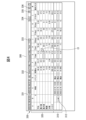
- 13 is a diagram showing an example of a history display screen generated by a history display control unit and displayed on a display unit;
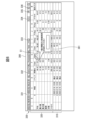
- FIG. 13 is a diagram showing a situation in which one statistical value is selected on the history display screen and the history information corresponding to that statistical value is highlighted.
- FIG. 13 is a diagram showing a situation in which a piece of history information is selected on the history display screen and a statistical value corresponding to the selected piece of history information is highlighted.
- FIG. 13 is a diagram showing a situation in which, in response to the selection of one of the statistical values in the statistics display area, an operation screen for specifying a threshold value or a numerical range related to this statistical value is displayed.
- FIG. 13 is a diagram showing an example of history information including a history image.
- FIG. 13 is a diagram showing an example of a setting adjustment screen presented by a playback function.
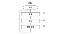
- 11 is a flowchart showing a process in which a detection program is executed to detect a workpiece in a robot system and store history information.
- 10 is a flowchart showing a basic flow regarding the display of history information by a history display control unit.
- the robot system 100 includes a robot 30 equipped with a hand 33 at the end of its arm, a robot controller 20 for controlling the robot 30, a teaching operation panel 10 connected to the robot controller 20, a visual sensor 70 attached to the end of the arm of the robot 30, an image processing device 50, and an external storage device 90.
- the robot system 100 can perform processes such as detection and judgment of an object 1 (hereinafter referred to as work 1) placed on a workbench 2 using the visual sensor 70, and handle the work 1.
- work 1 hereinafter referred to as work 1
- the robot system 100 also has a function of outputting and storing history information as a result of the execution of work.
- the function of the history management device 60 is incorporated into the image processing device 50, which is responsible for the control of the visual sensor 70 and the image processing function.
- the history management device 60 is responsible for storing history information and for displaying the history information and related information.
- the robot 30 as an industrial machine is assumed to be a vertical articulated robot here, but other types of robots, such as a Cartesian coordinate robot, a SCARA robot, or a parallel link robot, may also be used.
- the robot controller 20 controls the operation of the robot 30 according to an operation program loaded into the robot controller 20 or commands input from the teaching operation panel 10.
- the image processing device 50 is connected to the robot control device 20, and has the function of controlling the visual sensor 70 and performing various image processing according to commands from the robot control device 20.
- the image processing device 50 can detect the position of the workpiece 1 from an image captured by the visual sensor 70, and provide the detected position of the workpiece 1 to the robot control device 20. This allows the robot control device 20 to correct the taught position and perform operations such as removing the workpiece 1.
- the visual sensor 70 may be a camera that captures grayscale or color images, or a stereo camera or three-dimensional sensor that can obtain distance images or three-dimensional point clouds.
- the image processing device 50 holds a model pattern of the workpiece 1 and can execute image processing to detect the workpiece by pattern matching between the image of the workpiece in the captured image and the model pattern.
- the visual sensor 70 is assumed to have been calibrated, and the image processing device 50 is assumed to hold calibration data that defines the relative positional relationship between the visual sensor 70 and the robot 30. This makes it possible to convert positions on the image captured by the visual sensor 70 into positions on a coordinate system (such as the robot coordinate system) fixed to the working space.
- the teaching operation panel 10 may have a hardware configuration as a general computer, in which a processor is connected to a memory (ROM, RAM, non-volatile memory, etc.), a display unit, an operation unit consisting of input devices such as a keyboard and a touch panel (software key), an input/output interface, etc. via a bus.
- a processor is connected to a memory (ROM, RAM, non-volatile memory, etc.), a display unit, an operation unit consisting of input devices such as a keyboard and a touch panel (software key), an input/output interface, etc. via a bus.
- ROM read-only memory
- non-volatile memory etc.
- one or more workpieces 1 are repeatedly fed into the robot system 100, and the detection and handling of the workpieces is repeatedly performed, and history information for each execution of the detection process is stored.
- FIG. 2 shows a functional block diagram of the robot control device 20 and the image processing device 50.
- the robot control device 20 has a memory unit 22 and an operation control unit 121.
- the memory unit 22 is configured, for example, from a non-volatile memory or a hard disk drive, and stores operation programs and various other information.
- the operation control unit 121 controls the operation of the robot 30 in accordance with the operation program or commands from the teaching operation panel 10.
- the operation control unit 121 has the function of interpreting the operation program, etc., planning the trajectory of the robot 30, generating commands to control each axis of the robot 30, and executing servo control of the servo motors of each axis.
- the operation control unit 121 can provide the image processing device 50 (history management device 60) with machine control information of the robot 30.
- the machine control information of the robot 30 is the position (rotational position) of each joint axis and the position and orientation of a specific control part (e.g., TCP (tool center point)).
- the image processing device 50 (history management device 60) can include the machine control information obtained from the robot control device 20 as part of the history information regarding the execution results of processing using the visual sensor 70.
- the image processing device 50 includes a visual sensor control unit 151 and an image processing unit 152.
- the visual sensor control unit 151 has a function of controlling the visual sensor 70 according to a program related to image processing.
- the image processing unit 152 has a function of performing various image processing such as a process of detecting the position and orientation of a workpiece from a captured image by pattern matching.
- the visual sensor control unit 151 and the image processing unit 152 may be functional blocks realized by the processor of the image processing device 50 executing a program.
- the image processing device 50 includes a storage unit (not shown) that stores model data, calibration data, and various other information used in pattern matching. Note that FIG. 2 illustrates a display unit 52 and an operation unit 53 as hardware components of the image processing device 50.
- the history management device 60 includes a first memory unit 161, a memory control unit 162, a history display control unit 163, an output unit 164, and a setting adjustment unit 165.
- the memory control unit 162, the history display control unit 163, the output unit 164, and the setting adjustment unit 165 of the history management device 60 may be functional blocks realized by the processor of the image processing device 50 executing software (software related to history management and display).
- the first storage unit 161 is a relatively high-speed memory that stores the results of processing performed by the visual sensor 70 (including history images, processing results, parameter values, etc.) and history information including machine control information at the time of shooting. Note that when referring to a memory, terms such as high speed and low speed refer to the read/write speed.
- the first storage unit 161 can be configured, for example, as a volatile memory such as a DRAM or SRAM, but is not limited thereto.
- the first storage unit 161 has a capacity that can store multiple pieces of history information.
- the second memory unit 191 of the external storage device 90 is a slower and larger capacity memory than the first memory unit 161.
- the second memory unit 191 is not particularly limited, and may be configured, for example, by a non-volatile memory such as a flash memory, an SSD (Solid State Drive), a hard disk drive, or an optical disk drive.
- the second memory unit 191 has a capacity capable of storing history information acquired during the relatively long-term operation of the robot system 100.
- the second memory unit 191 may store history information transferred from the first memory unit 161, or history information may be directly written to the second memory unit 191 as a result of the execution of processing by the visual sensor 70.
- the external storage device 90 (second storage unit 191) may be defined as one of the functional elements constituting the history management device 60.
- the storage control unit 162 executes control related to the storage of history information, such as the storage of history information by the first storage unit 161, the storage of history information by the second storage unit 191, and the transfer of history information from the first storage unit 161 to the second storage unit 191.
- the storage control unit 162 can link image data obtained from the visual sensor 70, the results of processing (detection, determination, etc.) using the visual sensor 70, and machine control information, etc., and store them as a single piece of history information in the first storage unit 161 or the second storage unit 191.
- the storage control unit 162 may store the history information in the following operation procedure. (a1) Every time an image processing program (including photography) using a visual sensor is executed, history information is stored in the first storage unit 161. (a2) When the amount of data stored in the first memory unit 161 becomes full or exceeds a predetermined amount of data, the history information is transferred to the second memory unit 191 in order from oldest to newest, and the history information transferred to the second memory unit 191 is deleted from the first memory unit 161. By the above operation, the history information temporarily stored in the first storage unit 161 can be stored in the second storage unit 191 without omission.
- the history display control unit 163 has a function of displaying two or more pieces of history information together with statistical information relating to the two or more pieces of history information on the display unit 52.
- the history display control unit 163 can read out history information from the first storage unit 161 and the second storage unit 191, calculate statistical information relating to the history information, and display it on the display unit 52 together with the history information.
- the history display control unit 163 can also display two or more pieces of history information included in a specified selection condition out of the multiple pieces of history information stored in the first storage unit 161 and the second storage unit 191, together with statistical information relating to the two or more pieces of history information on the display unit 52.
- the output unit 164 provides a function to output the history information and statistical information displayed on the display unit 52 by the history display control unit 163 as a file in a specified format.
- the setting adjustment unit 165 has a function of restoring parameters included in the displayed history information to an image processing program (detection program, etc.) in response to a specified operation being performed on the displayed history information, and presenting a setting adjustment screen for adjusting the program and parameters.
- FIG. 3 shows an example of a history display screen 300 that is generated by the history display control unit 163 and displayed on the display unit 52.
- the history display screen 300 includes a history display area 310 that displays history information, and a statistics display area 320 that displays statistical information related to the history information.
- the history display screen 300 also includes an operation area 330 that includes a field for specifying selection conditions for the history information to be displayed and various operation buttons.
- the history information included in the selection conditions specified in the operation area 330 is displayed, for example, in chronological order.
- the size of the history display area 310 increases or decreases according to the number of pieces of history information included in the selection conditions.
- FIG. 3 shows a state in which three pieces of history information are displayed in a format in which the most recent one is displayed first and then the other way around. If the number of pieces of history information included in the selection conditions exceeds the number that can be displayed simultaneously in the history display screen 300, all of the history information included in the selection conditions may be displayed in a format that scrolls the screen.
- each piece of history information includes, as display items related to the detection results, the time (date and time), event, time (processing time), and X (mm), Y (mm), Z (mm), W (deg), P (deg), and R (deg) as the position and orientation information of the detected object.
- the statistics display area 320 displays statistical information related to the history information included in the history display area 310 (i.e., included in the selection conditions).
- the statistics display area 320 displays the average, minimum, maximum, range (numerical range), and variance as multiple types of statistical values related to the detection results (display items) included in the history information, namely, time (processing time), X (mm), Y (mm), Z (mm), W (deg), P (deg), and R (deg).
- the history information may include various information.
- the history information may include the number of detections, detection score, contrast, distortion, angle, etc. as detection results.
- the number of detections indicates the number of works detected in one detection process.
- the detection score indicates an evaluation value regarding the degree of match between the object on the image and the work model in the detection process.
- the contrast indicates the contrast of the outline of the object on the image against the background.
- the distortion indicates the degree of distortion of the object on the image relative to the work model.
- the angle indicates the deviation in the rotational direction of the object on the image relative to the work model.
- the statistical information may include statistical values (average value, minimum value, maximum value, range (numerical range), variance) for each of the number of detections, detection score, contrast, distortion, and angle.
- the operation area 330 includes a date and time specification field 331 for specifying the date and time range of the history information to be displayed, and an event specification field 332 for specifying the event of the history information to be displayed.
- a date and time range in the date and time specification field 331
- the history information included in the specified date and time range can be displayed and can also be used as the target for obtaining statistical information.
- the event specification field 332 provides a function for narrowing down the history information to be displayed (to be the target of statistical calculations) by specifying the type of processing (detection, determination, etc.). It is also possible to specify that the history information to be displayed is all the history information contained in the memory unit (first memory unit 161 and second memory unit 191).
- Operation area 330 further includes a download button 333, an auto update button 334, an update button 335, and a playback button 336.
- Pressing download button 333 outputs the displayed history information and statistical information as a data file in tabular format. Pressing download button 333 may display a screen for specifying the destination device or folder to which the data file is to be output. The function of outputting history information and statistical information as a file by pressing download button 333 is provided by output unit 164.
- the automatic update button 334 is a button for specifying whether to update the displayed history information and statistical information each time new history information is added to the first storage unit 161.
- the automatic update button 334 is a button for specifying whether to automatically update the history information and statistical information in real time. For example, if the date and time specification field 331 specifies that the display target is from a certain point in the past to the "present time", and the automatic update button 334 is pressed in this state, the history display control unit 163 adds new history information to the history display area each time the new history information is added to the first storage unit 161, and updates the statistical information using the history information. When the automatic update button 334 is not pressed, the history information and statistical information are not automatically updated. With this function of updating the history information and statistical information in real time, the user can always check the latest status of the execution results, and can also quickly check the execution results after adjusting parameters of a detection program, etc.
- the update button 335 provides a function for the user to manually update the history information. For example, when the update button 335 is pressed when it is specified in the date and time specification field 331 that the display target is from a certain point in the past to the "present time” and the automatic update button 334 has not been pressed, the history display control unit 163 updates the history information and statistical information to the latest state.
- the playback button 336 provides a function for restoring various setting parameters contained in the history information to a program and adjusting the program and parameters. For example, when a user selects desired history information and presses the playback button 336, the setting adjustment unit 165 restores various setting parameters contained in the selected history information to the program and presents a setting adjustment screen for adjusting the program.
- the history display control unit 163 can display history information and statistical information in a tabular format in the same table. Furthermore, on the history display screen 300, values relating to the same display item are displayed side-by-side in the same column. This display format allows the user to quickly and accurately grasp the relationship between each display item of the history information and its associated statistical value.
- multiple types of detection results (display items) included in each piece of history information are displayed aligned in the row direction, and multiple types of statistical values related to each detection result are displayed aligned in the column direction at the display positions in the alignment direction (row direction) of each detection result.
- multiple types of detection results included in each piece of history information may be displayed aligned in the column direction, and multiple types of statistical values related to each detection result may be displayed aligned in the row direction at the display positions in the alignment direction (column direction) of each detection result.
- the user can quickly and accurately grasp the state of the detection accuracy of the detection program and take necessary measures. For example, if the user recognizes a tendency in the displayed history information that the contrast varies greatly and the detection score is unstable, the user can determine that lighting is affecting it and take measures such as adding lighting.
- the user may change the parameters of the detection program based on the statistical values included in the statistical information. For example, the user can check the minimum value of the detection score, determine the detection score threshold based on that minimum value, and reflect it in the detection program. Alternatively, the user can set the detection score threshold of the detection program to a range of 3 sigma from the average detection score.
- FIG. 7 shows an example of an information display screen 210 that is displayed by selecting one piece of history information included in the history display area 310 and performing a predetermined operation.
- the information display screen 210 includes a history image G and display columns 211 for the number of detections, score (detection score), contrast, distortion, and angle.
- the information display screen 210 may be displayed in a window format simultaneously with the history display screen 300, or may be displayed independently as a display screen separate from the history display screen 300.
- the history display control unit 163 is responsible for these functions related to the presentation of the information display screen 210.
- the history display control unit 163 has a function of improving the convenience for the user by displaying the statistical information displayed in the statistics display area 320 in association with the history information displayed in the history display area 310.
- the history display control unit 163 can provide the following functions.
- (F1) A function of highlighting historical information corresponding to (including) the selected statistical value when a statistical value (e.g., the maximum value) displayed in the statistical display area 320 is selected.
- (F2) A function for highlighting a statistical value corresponding to a piece of history information when that piece of history information is selected from the history display area 310. For example, when the selected history information has a detection result (item) that has a maximum statistical value, the corresponding maximum value is highlighted in the statistics display area 320.
- FIG. 4 shows a display state in which the maximum Y value "13.5" in the statistical display area 320 is selected by the above function (F1), and the history information 312 having this maximum value is highlighted.
- highlighting can take various forms, such as changing the color, thickness, or font of the characters, or adding a color or pattern to the cell.
- the operation of selecting one of the statistical values may be performed by placing the cursor C1 on one of the statistical values and clicking the mouse, as shown in FIG. 4.
- the user can immediately check the history information corresponding to the selected statistical value (maximum value, etc.).
- the user can immediately adjust the parameters of the history information 312 by pressing the playback button 336 while the history information 312 is highlighted.
- function (F1) if the history information corresponding to the selected statistical value includes further information such as a history image, a transition to an information display screen that displays all the history information including the history image may be made in response to the selection of the statistical value.
- FIG. 5 shows a situation in which the statistical values corresponding to the detection results (display items) included in the history information 311 are highlighted in response to the selection of the history information 311 in the history display area 310 by the above function (F2).
- the operation of selecting one piece of history information may be performed by placing the cursor C1 on one piece of history information and clicking the mouse, as shown in FIG. 5 as an example.
- the Y value (“11.1") included in the selected history information 311 is the statistical minimum value
- the X value (“-50.3"), Z value ("80.5"), W value ("-31.2"), P value ("-90”), and R value ("0.1") are the statistical maximum values, so these statistical values are highlighted.
- the user can immediately confirm that the selected history information contains a statistically characteristic value (in this case, the maximum or minimum value).
- the history display control unit 163 may further have the following function (F3).
- F3 A function of presenting an operation screen for accepting an operation of specifying a threshold value (or a numerical range) for the selected statistical value in response to the selection of a statistical value included in the statistical information, and highlighting, from among the history information displayed in the history display area 310, history information that is selected based on the threshold value (or numerical range) specified via the operation screen.
- FIG. 6 shows a situation in which the operation screen 361 for specifying a threshold value for the statistical value is displayed in response to the "average value of X" included in the statistical information being selected by function (F3).
- the operation screen 361 may be presented, for example, by placing the cursor C1 on the statistical value and performing a specific operation (right-clicking and selecting the operation screen from the menu that appears).
- the operation screen 361 is configured to accept the specification of a threshold value for the X value.
- the history display control unit 163 may highlight, from among the history information included in the history display area 310, history information whose X value exceeds the specified threshold value (+10) (in the case of a negative value, the absolute value is greater than the threshold value (-10)).
- Function (F3) allows the user to quickly check, for example, a group of historical information whose statistical values are greater than a particular value, a group of historical information whose statistical values are less than a particular value, or a group of historical information whose statistical values fall within a particular numerical range.
- the user can instantly adjust parameters for the highlighted historical information using the playback function if necessary.
- function (F3) provides the functionality to search for historical information using selection criteria related to statistical values.
- the history display control unit 163 may further have a function (F4) for displaying statistical information based on a formula set by the user.
- the history display screen 300 in FIG. 3 shows, as an example, a state in which a formula (column F+column G+column H) is set by the user in column L (indicated by reference numeral 321) using function (F4), and the calculation result based on the formula is displayed in column L.
- the history display screen 300 in FIG. 3 also shows, as an example, a state in which a formula is specified in the row indicated by reference numeral 322 to calculate the sum of the numerical data of each display item of the first to third pieces of history information.
- the Eth to Lth columns of the row indicated by reference numeral 322 display the sum of the numerical values of the first to third pieces of history information corresponding to each column.
- the output data output by pressing the download button 333 also includes statistical information based on the formula set by the user.
- the history display control unit 163 may have a function (F5) that can exclude history information included in the history display area 310 from the calculations used to obtain the statistical information in the statistical display area 320. For example, as shown in FIG. 3, a check box 315 for specifying exclusion from statistical calculations may be added to each piece of history information. In this case, the history display control unit 163 excludes history information for which the check box 315 is checked from the statistical calculations, and recalculates and displays the statistical information. With this function (F5), the user can update the statistical information by excluding specific history information selected by looking at the statistical information (for example, history information whose detection position is significantly different from other history information).
- the history display function via the history display screen 300 as a user interface allows the user to evaluate the execution history based on the information the user considers important.
- the function that allows the user to set mathematical expressions allows the user to evaluate the history information using their own evaluation criteria.
- the history display screen 300 is also customizable.
- FIG. 8 shows an example of a setting adjustment screen 400 that is presented when the playback button 336 is pressed while a piece of history information displayed in the history display area 310 is selected or highlighted.
- the setting adjustment screen 400 includes a detection program display area 411 that displays the detection program, an image display area 412 for displaying a history image, a parameter display area 413, a detection result display area 414, and an operation button display area 415 that displays various operation buttons.
- a detection program titled "2D correction with one camera” is displayed.
- This detection program includes a snapshot icon 431, a pattern match icon 432, and a correction data calculation icon 433.
- the snapshot icon 431 represents a command to perform imaging using the visual sensor 70.
- the pattern match icon 432 represents a command to detect a workpiece by pattern matching the captured image.
- the correction data calculation icon 433 represents a command to calculate correction data for correcting the teaching position based on the position of the workpiece obtained by pattern matching.
- the image display area 412 displays a history image 452 of the history information that was selected or highlighted on the history display screen 300.
- the parameter display area 413 displays various parameters of the detection program with the restored parameter values in the history information that were selected or highlighted on the history display screen 300.
- Figure 8 shows a state in which a pattern match icon 432 is selected in the detection program display area 411, and various parameters related to the pattern match icon 432 are displayed in the parameter display area 413.
- the parameters of the pattern match icon 432 include a score threshold, a contrast threshold, and various other parameters. By selecting another icon in the detection program display area 411, the parameters for that icon (restored parameters) can be displayed in the parameter display area 413 and adjusted.
- the detection result display area 414 displays the processing results of the detection program.
- Figure 8 shows the state in which the detection result display area 414 displays the detection results (number of detections, position, score, contrast, etc.) contained in the history information that was selected or highlighted on the history display screen 300.
- Operation buttons for performing various operations are displayed in the operation button display area 415. After adjusting various parameters in the parameter display area 413, the user can press the detection button 441 to execute the detection program with the new parameters and check the results.
- the user can restore parameters from the history display screen 300 to the program and transition to the setting adjustment screen 400 where the parameters can be adjusted. Since the history information and statistical information are associated with each other on the history display screen 300, the user can select history information that requires adjustment by looking at the statistical information, and smoothly transition to the parameter adjustment screen to adjust the parameter value of that history information.
- FIG. 9 is a flowchart showing the process in which the detection program is executed to detect the workpiece 1 in the robot system 100 and store the history information.
- the detection program is executed to capture an image of the workpiece 1 by the visual sensor 70 (step S11).
- the image processing unit 152 of the image processing device 50 executes the detection process (step S12).
- the detection result (detected position of the workpiece 1) is used to control the robot 30 in the operation control unit 121.
- the history information is stored in the storage unit (first storage unit 161 and second storage unit 191) by the above-mentioned storage function (operation procedures (a1), (a2)) of the storage control unit 162 of the history management device 60 (step S13). Workpieces are repeatedly input into the robot system 100, and this process is repeatedly executed accordingly.
- history information is accumulated in the storage unit (first storage unit 161 and second storage unit 191), and the latest history information is added.
- FIG. 10 is a flowchart showing the basic flow of displaying history information by the history display control unit 163.
- This process (history display process) is executed under the control of the processor of the history management device 60 (the processor of the image processing device 50 in this embodiment).
- the history display process is started, for example, when a predetermined operation is performed to instruct the history management device 60 (image processing device 50) to display history.
- the history display control unit 163 reads out history information from the storage unit (first storage unit 161 and second storage unit 191) according to the selection conditions specified in the date and time specification field 331, etc., and displays it in the history display area 310 in the history display screen 300 (step S21).
- the history display control unit 163 calculates statistical information regarding the displayed history information and displays the calculated statistical information in the same table as the history information (step S22).
- step S23 corresponds to the case where the display of history up to the present is specified in the date and time specification field 331 and the automatic update button 334 is pressed.
- this history display process may be started in response to the occurrence of various events that should start this history display process (such as an operation of specifying selection conditions in the operation area 330, an operation of pressing the update button 335, an operation of pressing the automatic update button 334, etc.).
- the above-mentioned embodiment is an example of a configuration in which the robot system has a visual sensor as a sensor, and the history information relates to the result of detection processing based on an image captured by the visual sensor.
- the above-mentioned embodiment can also be applied to a configuration in which the robot system has various sensors and the history information includes at least one of the sensor output or the processing result based on the sensor output.
- the robot system is equipped with a force sensor between the flange at the tip of the robot arm and the tool (hand, etc.), and is configured to be able to execute a force control program based on the detection value of the force sensor.
- the force sensor outputs the external force acting on the robot (tool) as a detection value.
- the force control program may include a program for performing precision fitting, polishing work, etc.
- the control device that functions as a history management device executes the force control program and records the history information as the execution result.
- the history information may include the execution start date and time, the force control program name, the position where the force control was executed (the position of the control point), the detection value of the force sensor at that position (the force and moment in each axial direction), etc.
- the parameters of the force control program include, for example, the target pressing force, the force control gain, etc.
- the control device can, for example, calculate statistical information as in the above-described embodiment for multiple pieces of history information (detection values) recorded during multiple executions of the force control program, and display the statistical information together with the history information.
- history information detection values
- torque sensors arranged on each axis of the robot can be used as sensors for detecting external forces acting on the robot (tool).
- the configuration of the above-described embodiment can be applied to the display of history information output by the execution of work in an industrial machinery system that involves measurements by various sensors.
- a configuration in which the function of the history management device 60 is realized within the image processing device 50 is shown.
- this configuration is only an example, and there may be a configuration example in which the function of the history management device 60 is realized within the robot control device 20.
- the functional blocks constituting the history management device 60 may be arranged within the robot control device, and the external storage device 90 may be connected to the robot control device 20.
- the history display control unit 163 may display various screens such as a history display screen on the display unit of the teaching operation panel 10, and operation inputs to the history display screen, etc. may be accepted via the operation unit of the teaching operation panel 10 (or a touch panel screen integrated with the display unit, etc.).
- the function of the history management device 60 may be realized in the teaching pendant 10.
- the functional block of the history management device 60 is arranged in the teaching pendant 10.
- the external storage device 90 may be connected to the teaching pendant 10.
- the functional blocks of the history management device shown in FIG. 2 may be realized by one or more processors of the history management device executing various software stored in a storage device, or may be realized by a hardware-based configuration such as an ASIC (Application Specific Integrated Circuit).
- ASIC Application Specific Integrated Circuit
- each embodiment enables an operator to accurately and efficiently analyze execution history information output from a machine system.
- a history management device comprising a display unit (52) and a history display control unit (163) that displays two or more pieces of history information relating to the results of execution of a specified process by an industrial machine, together with statistical information relating to the two or more pieces of history information, on the display unit (52).
- the history management device (60) described in Appendix 1 is provided with a memory unit (161, 191) that stores multiple pieces of history information related to the results of execution of a specified process by the industrial machine, and the history display control unit (163) displays, from the multiple pieces of history information stored in the memory unit (161, 191), two or more pieces of history information that are included in specified selection conditions and statistical information related to the two or more pieces of history information.
- the history display control unit (163) highlights a statistical value in the statistical information corresponding to one piece of displayed history information in response to an operation of selecting one piece of displayed history information from the two or more pieces of displayed history information.
- the history display control unit (163) displays an operation screen on the display unit for specifying a threshold or numerical range for one statistical value included in the statistical information in response to an operation of selecting the one statistical value included in the statistical information, and highlights, from among the two or more pieces of displayed history information, history information that is selected based on the threshold or numerical range specified for the one selected statistical value.
- the history display control unit (163) accepts specification of a calculation formula using numerical data included in the statistical information or the history information, and displays a calculation result using the specified calculation formula.
- the history display control unit (163) receives an operation to specify history information to be excluded from the calculation of the statistical information among the two or more pieces of displayed history information.
- new history information is stored in the storage unit (161, 191) every time the industrial machine executes the predetermined process;
- the history display control unit (163) adds new history information, which is history information included in the specified selection conditions, to the storage unit, and displays the new history information on the display unit, and updates the statistical information based on the new history information.
- (Appendix 12) The history management device (60) described in any one of appendix 1 to 11, further comprising an output unit (164) that outputs the two or more pieces of history information and the statistical information displayed on the display unit as a file of a predetermined format.
- (Appendix 13) The history management device (60) according to any one of appendices 1 to 12, further comprising a setting adjustment unit (165) that, in response to a predetermined operation being performed while a piece of history information is selected or highlighted on the display unit (52), restores parameters included in the piece of history information to a program and displays a setting adjustment screen on the display unit for adjusting the program and the parameters.
- Appendix 14 14.
Landscapes
- Engineering & Computer Science (AREA)
- Robotics (AREA)
- Mechanical Engineering (AREA)
- Physics & Mathematics (AREA)
- General Physics & Mathematics (AREA)
- Automation & Control Theory (AREA)
- General Factory Administration (AREA)
Priority Applications (5)
| Application Number | Priority Date | Filing Date | Title |
|---|---|---|---|
| DE112023006012.6T DE112023006012T5 (de) | 2023-05-24 | 2023-05-24 | Verlaufsverwaltungsvorrichtung |
| CN202380098229.0A CN121100045A (zh) | 2023-05-24 | 2023-05-24 | 历史管理装置 |
| PCT/JP2023/019298 WO2024241526A1 (ja) | 2023-05-24 | 2023-05-24 | 履歴管理装置 |
| JP2025521722A JPWO2024241526A1 (https=) | 2023-05-24 | 2023-05-24 | |
| TW113115241A TW202446569A (zh) | 2023-05-24 | 2024-04-24 | 履歷管理裝置 |
Applications Claiming Priority (1)
| Application Number | Priority Date | Filing Date | Title |
|---|---|---|---|
| PCT/JP2023/019298 WO2024241526A1 (ja) | 2023-05-24 | 2023-05-24 | 履歴管理装置 |
Publications (1)
| Publication Number | Publication Date |
|---|---|
| WO2024241526A1 true WO2024241526A1 (ja) | 2024-11-28 |
Family
ID=93589759
Family Applications (1)
| Application Number | Title | Priority Date | Filing Date |
|---|---|---|---|
| PCT/JP2023/019298 Ceased WO2024241526A1 (ja) | 2023-05-24 | 2023-05-24 | 履歴管理装置 |
Country Status (5)
| Country | Link |
|---|---|
| JP (1) | JPWO2024241526A1 (https=) |
| CN (1) | CN121100045A (https=) |
| DE (1) | DE112023006012T5 (https=) |
| TW (1) | TW202446569A (https=) |
| WO (1) | WO2024241526A1 (https=) |
Citations (6)
| Publication number | Priority date | Publication date | Assignee | Title |
|---|---|---|---|---|
| JP2002351536A (ja) * | 2001-05-23 | 2002-12-06 | Ebara Corp | コンピュータによるフローシート上での物質収支の表示装置及び方法並びにフローシート上での物質収支の表示プログラムを記録したコンピュータ読み取り可能な記録媒体 |
| US20130055145A1 (en) * | 2011-08-29 | 2013-02-28 | John Melvin Antony | Event management apparatus, systems, and methods |
| WO2017126090A1 (ja) * | 2016-01-21 | 2017-07-27 | 三菱電機株式会社 | グラフ表示装置、グラフ表示方法及びグラフ表示プログラム |
| WO2018052015A1 (ja) * | 2016-09-14 | 2018-03-22 | 日本電気株式会社 | システムの分析支援装置、システムの分析支援方法及びプログラム |
| WO2021256017A1 (ja) * | 2020-06-16 | 2021-12-23 | オムロン株式会社 | コントローラ、システム、方法及びプログラム |
| WO2023053368A1 (ja) * | 2021-09-30 | 2023-04-06 | ファナック株式会社 | 教示装置及びロボットシステム |
-
2023
- 2023-05-24 WO PCT/JP2023/019298 patent/WO2024241526A1/ja not_active Ceased
- 2023-05-24 CN CN202380098229.0A patent/CN121100045A/zh active Pending
- 2023-05-24 DE DE112023006012.6T patent/DE112023006012T5/de active Pending
- 2023-05-24 JP JP2025521722A patent/JPWO2024241526A1/ja active Pending
-
2024
- 2024-04-24 TW TW113115241A patent/TW202446569A/zh unknown
Patent Citations (6)
| Publication number | Priority date | Publication date | Assignee | Title |
|---|---|---|---|---|
| JP2002351536A (ja) * | 2001-05-23 | 2002-12-06 | Ebara Corp | コンピュータによるフローシート上での物質収支の表示装置及び方法並びにフローシート上での物質収支の表示プログラムを記録したコンピュータ読み取り可能な記録媒体 |
| US20130055145A1 (en) * | 2011-08-29 | 2013-02-28 | John Melvin Antony | Event management apparatus, systems, and methods |
| WO2017126090A1 (ja) * | 2016-01-21 | 2017-07-27 | 三菱電機株式会社 | グラフ表示装置、グラフ表示方法及びグラフ表示プログラム |
| WO2018052015A1 (ja) * | 2016-09-14 | 2018-03-22 | 日本電気株式会社 | システムの分析支援装置、システムの分析支援方法及びプログラム |
| WO2021256017A1 (ja) * | 2020-06-16 | 2021-12-23 | オムロン株式会社 | コントローラ、システム、方法及びプログラム |
| WO2023053368A1 (ja) * | 2021-09-30 | 2023-04-06 | ファナック株式会社 | 教示装置及びロボットシステム |
Also Published As
| Publication number | Publication date |
|---|---|
| TW202446569A (zh) | 2024-12-01 |
| JPWO2024241526A1 (https=) | 2024-11-28 |
| DE112023006012T5 (de) | 2026-01-15 |
| CN121100045A (zh) | 2025-12-09 |
Similar Documents
| Publication | Publication Date | Title |
|---|---|---|
| CN109834695B (zh) | 进行机器人的示教操作的示教装置以及示教方法 | |
| EP2963513B1 (en) | Teaching apparatus and robot system | |
| JP3394322B2 (ja) | 視覚センサを用いた座標系設定方法 | |
| EP3354418A2 (en) | Robot control method and device | |
| EP3613548A1 (en) | Programming assistance apparatus, robot system, programming assistance method and program-generating method | |
| US11389954B2 (en) | Robot control device | |
| US11740062B2 (en) | Control device, measurement system, and measurement method | |
| US11839980B2 (en) | Image processing apparatus monitoring target, control method therefor, and storage medium storing control program therefor | |
| US12296486B2 (en) | Program editing device | |
| WO2024241526A1 (ja) | 履歴管理装置 | |
| CN109877828B (zh) | 机器点位调试方法、装置、计算机设备和存储介质 | |
| JP7469388B2 (ja) | 履歴管理装置及びプログラム | |
| JP7712373B2 (ja) | 教示装置及びロボットシステム | |
| WO2023026490A1 (ja) | 教示装置 | |
| TWI909177B (zh) | 教示裝置 | |
| JP7853332B2 (ja) | 制御装置 | |
| US12240109B2 (en) | Method of creating control program for robot, system executing processing of creating control program for robot, and non-transitory computer-readable storage medium | |
| US11514384B2 (en) | Productivity improvement support system and productivity improvement support method | |
| CN115427201B (zh) | 工业机械的显示装置 | |
| JP7328473B1 (ja) | 制御装置、産業機械のシステム、実行履歴データ表示方法、及びプログラム | |
| US20250375890A1 (en) | Robot apparatus, control method, and storage medium | |
| US20230321836A1 (en) | Correction device, correction method, and robot system | |
| TW202609482A (zh) | 教示裝置 | |
| CN120835821A (zh) | 控制装置以及机器人系统 | |
| CN115509171A (zh) | 仿真装置、仿真方法以及计算机可读的数据存储介质 |
Legal Events
| Date | Code | Title | Description |
|---|---|---|---|
| 121 | Ep: the epo has been informed by wipo that ep was designated in this application |
Ref document number: 23938489 Country of ref document: EP Kind code of ref document: A1 |
|
| ENP | Entry into the national phase |
Ref document number: 2025521722 Country of ref document: JP Kind code of ref document: A |
|
| WWE | Wipo information: entry into national phase |
Ref document number: 2025521722 Country of ref document: JP |
|
| WWE | Wipo information: entry into national phase |
Ref document number: 112023006012 Country of ref document: DE |
|
| WWP | Wipo information: published in national office |
Ref document number: 112023006012 Country of ref document: DE |