WO2024237293A1 - コネクタ - Google Patents
コネクタ Download PDFInfo
- Publication number
- WO2024237293A1 WO2024237293A1 PCT/JP2024/018029 JP2024018029W WO2024237293A1 WO 2024237293 A1 WO2024237293 A1 WO 2024237293A1 JP 2024018029 W JP2024018029 W JP 2024018029W WO 2024237293 A1 WO2024237293 A1 WO 2024237293A1
- Authority
- WO
- WIPO (PCT)
- Prior art keywords
- press
- plate
- fit
- pair
- housing
- Prior art date
- Legal status (The legal status is an assumption and is not a legal conclusion. Google has not performed a legal analysis and makes no representation as to the accuracy of the status listed.)
- Ceased
Links
Images




Classifications
-
- H—ELECTRICITY
- H01—ELECTRIC ELEMENTS
- H01R—ELECTRICALLY-CONDUCTIVE CONNECTIONS; STRUCTURAL ASSOCIATIONS OF A PLURALITY OF MUTUALLY-INSULATED ELECTRICAL CONNECTING ELEMENTS; COUPLING DEVICES; CURRENT COLLECTORS
- H01R12/00—Structural associations of a plurality of mutually-insulated electrical connecting elements, specially adapted for printed circuits, e.g. printed circuit boards [PCB], flat or ribbon cables, or like generally planar structures, e.g. terminal strips, terminal blocks; Coupling devices specially adapted for printed circuits, flat or ribbon cables, or like generally planar structures; Terminals specially adapted for contact with, or insertion into, printed circuits, flat or ribbon cables, or like generally planar structures
- H01R12/70—Coupling devices
- H01R12/71—Coupling devices for rigid printing circuits or like structures
Definitions
- This disclosure relates to connectors.
- the connector disclosed in Patent Document 1 includes a connector housing (hereinafter also referred to as the housing) that is mounted on a circuit board, and a fixing bracket (hereinafter also referred to as the peg) for soldering to the circuit board.
- a connector housing hereinafter also referred to as the housing
- a fixing bracket hereinafter also referred to as the peg
- press-fit mounting sections that press-fit and hold the press-fit sections (hereinafter also referred to as the press-fit protrusions) that protrude outward from the outer edges of the pegs.
- the purpose of this disclosure is to increase the fixing force between the housing and the peg.
- the connector of the present disclosure comprises: a housing having a pair of outer wall surfaces located at both ends in a width direction, the outer wall surfaces being formed with a press-fit portion; a metal peg having a fixing portion fixed to a circuit board and a plate-like portion arranged to cover the outer wall surface, the metal peg being fixed to the housing by pressing a press-fit protrusion protruding from an outer edge of the plate-like portion into the press-fit portion;
- the plate-shaped portion is located in an area spaced from the outer edge of the plate-shaped portion and has a locking portion that bites into the outer wall surface.
- the fixing force between the housing and the peg can be increased.
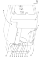
- FIG. 1 is a perspective view of a connector according to a first embodiment.
- FIG. 2 is an enlarged perspective view of the connector of the first embodiment.
- FIG. 3 is a perspective view of a peg provided in the connector of the first embodiment.
- FIG. 4 is a side cross-sectional view of the connector of the first embodiment.
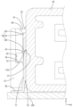
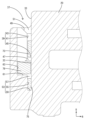
- FIG. 5 is an enlarged front cross-sectional view showing a locking portion of the connector of the first embodiment.
- FIG. 6 is an enlarged front cross-sectional view showing a reinforcing portion of the connector of the first embodiment.
- FIG. 7 is a perspective view of a terminal fitting included in the connector of the first embodiment.
- the connector of the present disclosure comprises: (1) A housing having a pair of outer wall surfaces located at both ends in a width direction and a press-fit portion formed on the outer wall surfaces, and a metal peg having a fixing portion fixed to a circuit board and a plate-like portion arranged to cover the outer wall surfaces, the metal peg having a press-fit protrusion protruding from an outer edge of the plate-like portion press-fitted into the press-fit portion, the plate-like portion being located in an area spaced from the outer edge of the plate-like portion and having a locking portion that bites into the outer wall surface.
- the peg is fixed to the housing not only by the press-fitting of the press-fit protrusion into the press-fit portion, but also by the locking portion biting into the outer wall surface.
- the plate-shaped portion has a pair of first notches that extend in a direction intersecting the circuit board at positions spaced apart in the front-rear direction while penetrating in the plate thickness direction, and a second notch that penetrates in the plate thickness direction and connects the ends of the pair of first notches that are farther from the circuit board, and the portion of the plate-shaped portion that is partitioned by the pair of first notches and the second notch and that is inclined toward the outer wall surface functions as the locking portion.
- the extending end surface of the locking portion bites into the outer wall surface so as to support it from the circuit board side, preventing displacement of the housing toward the circuit board during reflow.
- the locking portion has a rectangular shape with the second cutout portion as its long side.
- the press-in projection includes a first press-in projection and a second press-in projection arranged at a distance in the length direction of the first cut-out portion on both front and rear side edges of the plate-like portion, and the formation range of the first cut-out portion is set only in the area between the first press-in projection and the second press-in projection.
- the first press-in projection and the second press-in projection are arranged at a position offset in the length direction of the first cut-out portion from a portion of the plate-like portion where a decrease in rigidity is a concern due to the formation of the first cut-out portion and the second cut-out portion. Therefore, the fixing force by pressing the press-in portion and the press-in projection is highly reliable.
- the plate-like portion has a pair of reinforcing portions extending outward in the width direction from the front and rear side edges of the plate-like portion between the first press-fit protrusion and the second press-fit protrusion.
- the outer wall surface has a first restriction surface that faces the reinforcing portion from the fixing portion side.
- the outer wall surface has a second restriction surface that restricts the relative outward movement of the reinforcing portion with respect to the outer wall surface in the width direction.
- the connector 10 includes a housing 20 and a peg 70.
- the "front side” is represented by “F” in Figs. 1-4 and 1-7 in the front-rear direction.
- the “upper side” is represented by “U” in each figure in the up-down direction.
- the “right side” is represented by “R” in Figs. 1-3 and 1-5-7 in the left-right direction.
- the width direction of the housing is the left-right direction in this embodiment 1.
- the housing 20 is made of synthetic resin. As shown in Fig. 1, the housing 20 has a wall portion 21 extending in the width direction and arranged with its plate thickness direction facing the front-rear direction, and a hood portion 23 protruding forward in a rectangular tubular shape from the outer peripheral edge of the wall portion 21. A mating connector (not shown) is fitted into the hood portion 23.
- the hood portion 23 has an upper wall 25 and a lower wall 27 arranged at an interval in the vertical direction, and a pair of side walls 29 arranged at an interval in the left-right direction.
- the wall portion 21 has a plurality of press-fitting holes 31 for press-fitting terminal fittings 90 described later.
- the outer surfaces of the pair of side walls 29 formed on the housing 20 are defined as the outer wall surface 33.
- the connector 10 has a press-fit portion 30 on the outer wall surface 33 of the housing 20.
- the press-fit portion 30 is formed with a first press-fit recess 39 and a second press-fit recess 53.
- the peg 70 is fixed to the housing 20 by being pressed into the first press-fit recess 39 and the second press-fit recess 53. As shown in FIG.
- a first press-fit protrusion 73 of the peg 70 which will be described later, is pressed into the first press-fit recess 39, and a second press-fit protrusion 75 of the peg 70 is pressed into the second press-fit recess 53.
- the press-fit portion 30 is a portion that protrudes outward in the width direction of the housing 20 from the front end and rear end of each outer wall surface 33.
- a pair of front and rear press-fit portions 30 face each other in the front-rear direction.
- a pair of first press-fit recesses 39 having a vertically elongated slit shape are formed at the upper ends of the pair of press-fit portions 30 so as to face each other in the front-rear direction.
- one first press-fit recess 39 is formed by a first opposing wall 41, a first side wall 43, and a first bottom wall 45.
- the first opposing wall 41 is formed so as to face the outer wall surface 33.
- the first side wall 43 connects the outer wall surface 33 and the first opposing wall 41.
- the first bottom wall 45 forms the bottom of the space surrounded by the outer wall surface 33, the first opposing wall 41, and the first side wall 43.
- the first bottom wall 45 has an inclined surface 47 that slopes downward toward the center of the outer wall surface 33 in the front-rear direction (as it moves away from the first side wall 43) at the end of the outer wall surface 33 in the front-rear direction.
- the first opposing wall 41 has an inclined surface 47 that slopes downward toward the center of the outer wall surface 33 in the front-rear direction (as it moves away from the first side wall 43).
- the first opposing wall 41 has an inclined surface 47 that slopes downward toward the center in the front-rear direction.
- the first opposing wall 41 has an inclined surface 49 that slopes downward toward the center in the width direction.
- the first side wall 43 has an inclined surface 51 that slopes downward toward the center in the front-rear direction.
- the first press-fit recess 39 is formed in each of the pair of press-fit portions 30.
- a second press-fit recess 53 having a vertically elongated slit shape in the front-rear direction is formed at the lower end of the press-fit portion 30.
- the second press-fit recess 53 is formed in each of the pair of press-fit portions 30.
- the pair of second press-fit recesses 53 is formed lower than the pair of first press-fit recesses 39.
- the second press-fit recess 53 is formed by a second opposing wall 55, a second side wall 57, and a second bottom wall 59.
- the second opposing wall 55 is formed to face the outer wall surface 33.
- the pair of second side walls 57 connect the front ends of the outer wall surface 33 and the second opposing wall 55, and the rear ends of the outer wall surface 33 and the second opposing wall 55.
- the second bottom wall 59 forms the bottom of the space surrounded by the outer wall surface 33, the second opposing wall 55, and the second side wall 57. As shown in FIG. 4, the second side wall 57 is formed closer to the center of the outer wall surface 33 in the front-to-rear direction than the first side wall 43.
- the press-fit portion 30 has a first regulating surface 61.
- the first regulating surface 61 is connected to the upper end of the second opposing wall 55 and extends vertically from the upper end of the second opposing wall 55 toward the outside in the width direction of the housing 20.
- the first regulating surface 61 is formed on each of the pair of press-fit portions 30.
- the first regulating surface 61 is positioned so as to face, at a distance, the lower end of the reinforcing portion 79 described below.
- the first regulating surface 61 is formed at a height between the first bottom wall 45 and the second bottom wall 59.
- the press-fit portion 30 has a second regulating surface 63.
- the second regulating surface 63 is connected to the outer end of the first regulating surface 61 in the width direction of the housing 20, and extends vertically upward relative to the first regulating surface 61.
- the second regulating surface 63 is formed to face the outer wall surface 33. As shown in FIG. 4, the second regulating surface 63 is formed closer to the center of the housing 20 in the front-to-rear direction than the first side wall 43.
- the peg 70 is made of metal.
- the peg 70 is a single component having a plate-shaped portion 71 and a fixing portion 85.
- the plate-shaped portion 71 is attached to the housing 20 by being press-fitted into the press-fit portion 30, and is disposed so as to cover the outer wall surface 33.
- the fixing portion 85 protrudes outward in the width direction of the housing 20 from the lower end portion of the plate-shaped portion 71.
- the fixing portion 85 is fixed to the circuit board 100 by soldering.
- the plate-shaped portion 71 has a flat plate shape with the plate thickness direction facing the left-right direction.
- the plate-shaped portion 71 has a pair of press-fit protrusions 72, one locking portion 77, and a pair of reinforcing portions 79.
- the pair of press-fit protrusions 72 is composed of a pair of front and rear first press-fit protrusions 73 and a pair of front and rear second press-fit protrusions 75.
- the pair of first press-fit protrusions 73 are portions that protrude from both front and rear outer edges 71S of the plate-shaped portion 71 at the upper end of the plate-shaped portion 71. As shown in FIG.
- the pair of first press-fit protrusions 73 are pressed into a pair of first press-fit recesses 39.
- the pair of second press-fit protrusions 75 are portions that protrude from both front and rear outer edges 71S at the lower portion of the plate-shaped portion 71.
- the pair of second press-fit protrusions 75 are pressed into a pair of second press-fit recesses 53.
- the pair of reinforcing portions 79 extend from the front and rear outer edges 71S of the plate-shaped portion 71 perpendicular to the outer wall surface 33 between the first press-fit projection 73 and the second press-fit projection 75 outward in the width direction toward the second restriction surface 63. As shown in FIG.
- the upper end of the reinforcing portion 79 is located lower than the lower end of the first press-fit projection 73.
- the lower end of the reinforcing portion 79 is located higher than the upper end of the second press-fit projection 75.
- the reinforcing portion 79 is located directly above the first restriction surface 61, facing the first restriction surface 61 at a distance.
- the locking portion 77 is formed on the plate-shaped portion 71 as shown in FIG. 4.
- the locking portion 77 is disposed between the lower end of the first press-fit projection 73 and the upper end of the second press-fit projection 75 in the up-down direction.
- a pair of front and rear first cut-outs 81 are formed on the plate-shaped portion 71.
- the pair of first cut-outs 81 penetrate the plate-shaped portion 71 in the plate thickness direction and extend in a direction intersecting the circuit board 100 at positions spaced apart in the front-rear direction.
- a second cut-out 83 is formed on the plate-shaped portion 71.
- the second cut-out 83 penetrates the plate-shaped portion 71 in the plate thickness direction and extends in the front-rear direction so as to connect the upper ends of the pair of first cut-outs 81.
- the portion of the plate-shaped portion 71 that is defined by the pair of first cut-outs 81 and the second cut-out 83 and inclined toward the outer wall surface 33 functions as the locking portion 77.
- the pair of first cutouts 81 extend in parallel to each other upward from a height directly above the second press-fit projection 75 to a height directly below the first press-fit projection 73. As shown in FIG.
- the locking portion 77 is a rectangular area of the plate-shaped portion 71 surrounded by a pair of first cutouts 81, a second cutout 83, and a line segment L connecting the lower ends of the first cutouts 81.
- the locking portion 77 protrudes toward the housing 20 side (the outer wall surface 33 side) from the inner surface (the surface facing the outer wall surface 33) of the plate-shaped portion 71 by cutting and raising.
- the upper end of the locking portion 77 protrudes toward the housing 20 side (the outer wall surface 33 side) from the inner surface (the surface facing the outer wall surface 33) of the plate-shaped portion 71.
- the locking portion 77 is in an oblique position with respect to the plate-shaped portion 71 and the outer wall surface 33.
- the locking portion 77 is cut and raised so that it extends upward in a cantilever shape.
- a terminal fitting 90 is press-fitted into the housing 20.
- the front end of the terminal fitting 90 protrudes into the hood portion 23.
- the terminal fitting 90 is made of a conductive metal and is formed by bending a thin rod having a substantially rectangular cross section at two positions at substantially right angles.
- the terminal fitting 90 has a terminal connection portion 91 that extends linearly in the front-rear direction and a board connection portion 93 that is connected to the terminal connection portion 91.
- a convex portion 97 is formed at the rear end of the terminal connection portion 91.
- the board connection portion 93 is connected to the rear end of the terminal connection portion 91 via a first bend portion 95 and extends downward from the first bend portion 95.
- the board connection portion 93 is bent into an L-shape in a side view of the terminal fitting 90.
- the rear end of the board connection portion 93 is connected to the circuit board 100.
- the surface of the terminal fitting 90 is gold plated to ensure good electrical connection with the mating terminal (not shown).
- the connector 10 is mounted on the circuit board 100 as follows. First, the terminal fittings 90 are press-fitted into the press-fit holes 31 of the housing 20. The terminal fittings 90 are positioned relative to the housing 20 by causing the protrusions 97 of the terminal fittings 90 to bite into the inner walls of the press-fit holes 31. When the terminal fittings 90 are positioned in place, the front ends of the terminal fittings 90 protrude into the hood portion 23.
- the peg 70 is attached to the housing 20. Specifically, the first press-in protrusion 73 of the peg 70 is pressed into the first press-in recess 39 from above. As shown in FIG. 6, the plate thickness of the first press-in protrusion 73 is approximately the same as the left-right width of the first press-in recess 39, so that the peg 70 is fixed to the housing 20 by pressing in the first press-in protrusion 73.
- the first press-in recess 39 has a shape that makes it easy to press in the first press-in protrusion 73 due to the inclined surface 47, first tapered portion 49, and second tapered portion 51.
- the second press-fit protrusion 75 is pressed into the second press-fit recess 53 from above.
- the plate thickness of the second press-fit protrusion 75 is approximately the same as the left-right width of the second press-fit recess 53, so the peg 70 is positioned relative to the housing 20 by pressing in the second press-fit protrusion 75.
- the upward extending end surface 77U (upper end surface) of the locking portion 77 bites into the outer wall surface 33 from the outside in the width direction.
- the extended end surface 77U penetrates into the inside of the outer wall surface 33 and abuts against the inside of the outer wall surface so as to support it from below, preventing downward displacement of the housing 20 relative to the peg 70.
- the peg 70 is fixed to the housing 20 at five different points by a pair of first press-fit projections 73, a pair of second press-fit projections 75, and the locking portion 77, so that the peg 70 and the housing 20 are unlikely to be displaced relative to each other due to external forces.
- the connector 10, with the terminal fittings 90 and pegs 70 attached to the housing 20, is mounted on the circuit board 100 by reflow. Specifically, the rear end of the board connection portion 93 of each terminal fitting 90 and the fixing portion 85 of the peg 70 are placed on solder paste formed on the surface of the circuit board 100. The solder is then melted in a reflow furnace (not shown). It is then cooled and solidified, and the peg 70 is soldered and fixed to the circuit board 100. As a result, the board connection portion 93 of each terminal fitting 90 is soldered and connected to the conductive portion of the circuit board 100.
- both ends of the housing 20 in the width direction tend to displace downward relative to the peg 70.
- both ends of the housing 20 in the width direction are prevented from displacing downward relative to the peg 70. Therefore, the connector 10 of this embodiment 1 can prevent deformation of the housing 20 even in a high-temperature environment such as inside a reflow furnace. This ensures the reliability of the connection of the connector 10 with the circuit board 100.
- the above reflow process completes the assembly and mounting of the connector 10.
- the connector 10 of the first embodiment includes a housing 20 and a metal peg 70.
- the housing 20 has a pair of outer wall surfaces 33 located at both ends in the width direction.
- a press-in portion 30 is formed on the outer wall surface 33.
- the metal peg 70 has a fixing portion 85 that is fixed to the circuit board 100 and a plate-shaped portion 71 arranged to cover the outer wall surface 33.
- the plate-shaped portion 71 has a pair of first press-in projections 73 and a pair of second press-in projections 75 that protrude from both front and rear outer edges 71S.
- the peg 70 is fixed to the housing 20 by pressing the first press-in projections 73 into the first press-in recess 39 and pressing the second press-in projections 75 into the second press-in recess 53.
- the plate-shaped portion 71 has a locking portion 77 that is located in an area separated in the front-rear direction from both front and rear outer edges 71S of the plate-shaped portion 71 and bites into the outer wall surface 33. According to this configuration, the peg 70 is fixed to the housing 20 not only by the press-fitting projection 72 being pressed into the press-fitting portion 30, but also by the engagement of the locking portion 77 into the outer wall surface 33.
- the first press-fitting projection 73 and the second press-fitting projection 75 of the peg 70 are respectively engaged with the first press-fitting recess 39 and the second press-fitting recess 53.
- the peg 70 is fixed in the front-rear direction relative to the housing 20.
- the engagement portion 77 is engaged with the outer wall surface 33, so that the peg 70 is fixed in the up-down direction and the left-right direction relative to the housing 20.
- the connector 10 can reduce the displacement of the housing 20 toward the circuit board 100 during reflow, ensuring the connection reliability between the connector 10 and the circuit board 100.
- the plate-shaped portion 71 has a pair of front and rear first cut-outs 81.
- the pair of first cut-outs 81 penetrate the plate-shaped portion 71 in the plate thickness direction and extend in the up-down direction intersecting the circuit board 100 at positions spaced apart in the front-to-rear direction.
- the plate-shaped portion 71 has one second cut-out 83.
- the second cut-out 83 penetrates the plate-shaped portion 71 in the plate thickness direction and connects the ends of the pair of first cut-outs 81 that are farther from the circuit board 100.
- the portion of the plate-shaped portion 71 that is partitioned by the pair of first cut-outs 81 and second cut-outs 83 to have a cantilevered shape and that is inclined toward the outer wall surface 33 functions as the engagement portion 77.
- the extended end surface 77U of the locking portion 77 bites into the outer wall surface 33 to support the circuit board 100, preventing the housing 20 from displacing toward the circuit board 100 during reflow.
- the locking portion 77 is rectangular with the second cutout 83 as its long side. With this configuration, the locking area (amount of penetration) of the extended end surface 77U of the locking portion 77 into the outer wall surface 33 can be increased compared to when the locking portion 77 is rectangular with the first cutout 81 as its long side, so that displacement of the housing 20 in the direction approaching the circuit board 100 during reflow can be effectively prevented.
- the press-in protrusions 72 include a first press-in protrusion 73 and a second press-in protrusion 75 that are spaced apart in the length direction of the first cut-out portion 81 on both front and rear side edges of the plate-shaped portion 71.
- the formation range of the first cut-out portion 81 is set only in the area between the first press-in protrusion 73 and the second press-in protrusion 75.
- the first press-in protrusion 73 and the second press-in protrusion 75 are positioned in a position that is offset in the length direction of the first cut-out portion 81 from the portion of the plate-shaped portion 71 where there is concern that the rigidity may be reduced due to the formation of the first cut-out portion 81 and the second cut-out portion 83. Therefore, the fixing force provided by the press-in of the press-in portion 30 and the press-in protrusion 72 is highly reliable.
- the plate-shaped portion 71 has a pair of reinforcing portions 79 extending outward in the width direction from the front and rear outer edges 71S of the plate-shaped portion 71 between the first press-fit protrusion 73 and the second press-fit protrusion 75.
- the portions of the plate-shaped portion 71 between the front and rear outer edges 71S and the first cut-out portion 81 are reinforced by the reinforcing portions 79. This makes it possible to prevent a decrease in the rigidity of the plate-shaped portion 71 caused by the formation of the pair of first cut-out portions 81 and second cut-out portions 83.
- the outer wall surface 33 has a first restricting surface 61 that faces the reinforcing portion 79 from the fixing portion 85 side. With this configuration, the reinforcing portion 79 engages with the first restricting surface 61, thereby restricting the relative movement of the peg 70 toward the fixing portion 85 side with respect to the housing 20.
- the outer wall surface 33 has a second restricting surface 63 that restricts the outward movement of the reinforcing portion 79 relative to the outer wall surface 33 in the width direction.
- the plate-shaped portion 71 engages with the second restricting surface 63, thereby restricting the outward movement of the peg 70 relative to the housing 20 in the width direction.
- the press-fit protrusion 72 of the first embodiment may be constituted by only one of the first press-fit protrusion 73 and the second press-fit protrusion 75, for example.
- the press-in portion 30 of this embodiment 1 has a first press-in recess 39 for pressing in the first press-in protrusion 73 and a second press-in recess 53 for pressing in the second press-in protrusion 75.
- the press-in protrusion 72 has a structure that allows it to be pressed in, the shapes of the first press-in recess 39 and the second press-in recess 53 are not important.
- the pair of first cut-out portions 81 may extend from a position below the upper end of the second press-fit projection 75 to a position above the lower end of the first press-fit projection 73.
- the pair of first cut-out portions 81 do not need to be parallel to each other.
- the second cut-out portion 83 does not need to connect the upper ends of the first cut-out portions 81.
- the second cut-out portion 83 may connect portions that are lower than the upper ends of the first cut-out portions 81.
- a pair of upper and lower locking portions are formed on the plate-shaped portion with the second cut-out portion as a boundary.
- the upper end of the reinforcing portion 79 may be located higher than the lower end of the first press-fit projection 73.
- the lower end of the reinforcing portion 79 may be located lower than the upper end of the second press-fit projection 75.
- the second restriction surface 63 of the first embodiment may extend at an obtuse angle or an acute angle with respect to the first restriction surface 61 .
- the first restriction surface 61 does not need to be provided in the press-fit portion 30.
- the first restriction surface 61 may extend from a position spaced apart from the press-fit portion 30 on the outer wall surface 33 so as to face the reinforcing portion 79 from the fixing portion 85 side.
- the second restriction surface 63 does not need to be provided on the press-fit portion 30.
- the second restriction surface 63 may extend from a position spaced apart from the press-fit portion 30 so as to restrict the relative displacement of the plate-like portion 71 outward in the width direction with respect to the reinforcing portion 79.
Landscapes
- Coupling Device And Connection With Printed Circuit (AREA)
- Connector Housings Or Holding Contact Members (AREA)
Abstract
ハウジングとペグとの固定力を高める。 幅方向の両端部に位置する一対の外壁面(33)を有し、外壁面(33)に圧入部(30)が形成されたハウジング(20)と、回路基板(100)に固着される固着部(85)と、外壁面(33)を覆うように配置された板状部(71)と、を有し、板状部(71)の外縁部から突出した圧入突起(72)を圧入部(30)に圧入することによってハウジング(20)に固定された金属製のペグ(70)と、を備え、板状部(71)は、板状部(71)の外縁部から離隔した領域に位置し、外壁面(33)に食い込む係止部(77)を有する。
Description
本開示は、コネクタに関する。
特許文献1に開示のコネクタは、回路基板に実装されるコネクタハウジング(以下、ハウジングともいう。)と、回路基板とはんだ固定するための固定金具(以下、ペグともいう。)を備えている。ハウジングの両側面には、ペグの外側縁から外側に突出する圧入部(以下、圧入突起部ともいう。)を圧入して保持する圧入装着部が形成されている。
しかし、上記のペグは、圧入突起部と、圧入装着部との嵌合のみによって、ハウジングに固定されていたため、ハウジングとの固定力が弱く、例えば、リフローの際にハウジングが変形し、ハウジングが回路基板側に変位するおそれがあった。
本開示は、ハウジングとペグとの固定力を高めることを目的とする。
本開示のコネクタは、
幅方向の両端部に位置する一対の外壁面を有し、前記外壁面に圧入部が形成されたハウジングと、
回路基板に固着される固着部と、前記外壁面を覆うように配置された板状部と、を有し、前記板状部の外縁部から突出した圧入突起を前記圧入部に圧入することによって前記ハウジングに固定された金属製のペグと、を備え、
前記板状部は、前記板状部の外縁部から離隔した領域に位置し、前記外壁面に食い込む係止部を有するコネクタ。
幅方向の両端部に位置する一対の外壁面を有し、前記外壁面に圧入部が形成されたハウジングと、
回路基板に固着される固着部と、前記外壁面を覆うように配置された板状部と、を有し、前記板状部の外縁部から突出した圧入突起を前記圧入部に圧入することによって前記ハウジングに固定された金属製のペグと、を備え、
前記板状部は、前記板状部の外縁部から離隔した領域に位置し、前記外壁面に食い込む係止部を有するコネクタ。
本開示によれば、ハウジングとペグとの固定力を高めることができる。
[本開示の実施形態の説明]
本開示のコネクタは、
(1)幅方向の両端部に位置する一対の外壁面を有し、前記外壁面に圧入部が形成されたハウジングと、回路基板に固着される固着部と、前記外壁面を覆うように配置された板状部と、を有し、前記板状部の外縁部から突出した圧入突起を前記圧入部に圧入することによって前記ハウジングに固定された金属製のペグと、を備え、前記板状部は、前記板状部の外縁部から離隔した領域に位置し、前記外壁面に食い込む係止部を有する。この構成によれば、ペグは、圧入部に対する圧入突起の圧入に加え、外壁面に対する係止部の食い込みによってもハウジングに固定される。
本開示のコネクタは、
(1)幅方向の両端部に位置する一対の外壁面を有し、前記外壁面に圧入部が形成されたハウジングと、回路基板に固着される固着部と、前記外壁面を覆うように配置された板状部と、を有し、前記板状部の外縁部から突出した圧入突起を前記圧入部に圧入することによって前記ハウジングに固定された金属製のペグと、を備え、前記板状部は、前記板状部の外縁部から離隔した領域に位置し、前記外壁面に食い込む係止部を有する。この構成によれば、ペグは、圧入部に対する圧入突起の圧入に加え、外壁面に対する係止部の食い込みによってもハウジングに固定される。
(2)(1)に記載のコネクタにおいて、前記板状部は、板厚方向に貫通しつつ、前後方向に離隔した位置において、前記回路基板と交差する方向に延びる一対の第1切込み部と、板厚方向に貫通しつつ、一対の前記第1切込み部の前記回路基板から遠い側の端部同士を繋ぐ第2切込み部と、を有し、前記板状部のうち前記一対の第1切込み部と前記第2切込み部とによって区画され、且つ前記外壁面側へ傾いた部位が、前記係止部として機能する。この構成によれば、係止部の延出端面が、外壁面に対して回路基板側から支持するように食い込むため、リフロー時におけるハウジングの回路基板側への変位を防止できる。
(3)(2)に記載のコネクタにおいて、前記係止部は、前記第2切込み部を長辺とする長方形をなしている。この構成によれば、係止部が第1切込み部を長辺とする長方形をなしている場合に比べると、係止部の延出端面における外壁面への係止面積を増やせるため、リフロー時におけるハウジングの回路基板に接近する方向への変位を効果的に防止できる。
(4)(3)に記載のコネクタにおいて、前記圧入突起は、前記板状部の前後両側縁において、前記第1切込み部の長さ方向に離隔して配置された第1圧入突起と第2圧入突起とを含み、前記第1切込み部の形成範囲が、前記第1圧入突起と前記第2圧入突起との間の領域のみに設定されている。この構成によれば、第1圧入突起と第2圧入突起は、板状部のうち第1切込み部と第2切込み部の形成に起因して剛性低下が懸念される剛性低下懸念部位から第1切込み部の長さ方向へ外れた位置に配置される。したがって、圧入部と圧入突起との圧入による固定力の信頼性に優れている。
(5)(4)に記載のコネクタにおいて、前記板状部は、前記第1圧入突起と、前記第2圧入突起との間において、前記板状部の前記前後両側縁から、前記幅方向の外側に延出した一対の補強部を有する。この構成によれば、板状部のうち前後両側縁と第1切込み部との間の部位が、補強部によって補強される。よって、一対の第1切込み部、及び第2切込み部の形成に起因する板状部の剛性低下を防止できる。
(6)(5)に記載のコネクタにおいて、前記外壁面は、前記補強部に対して前記固着部側から対向する第1規制面を有する。この構成によれば、補強部が第1規制面に係止することによって、ハウジングに対するペグの固着部側への相対移動を規制することができる。
(7)(5)又は(6)に記載のコネクタにおいて、前記外壁面は、前記外壁面に対する前記補強部の前記幅方向外側への相対変位を規制する第2規制面を有する。この構成によれば、板状部が第2規制面に係止することによって、ハウジングに対するペグの幅方向外側への相対移動を規制することができる。
[本開示の実施形態の詳細]
本開示の実施形態を、以下に図面を参照しつつ説明する。本開示は、これらの例示に限定されるものではなく、請求の範囲によって示され、請求の範囲と均等の意味および範囲内でのすべての変更が含まれる。
本開示の実施形態を、以下に図面を参照しつつ説明する。本開示は、これらの例示に限定されるものではなく、請求の範囲によって示され、請求の範囲と均等の意味および範囲内でのすべての変更が含まれる。
[実施形態1]
コネクタ10は、ハウジング20と、ペグ70とを備えている。以下の説明において、前後方向については、図1-4,7において、「前側」を「F」で表している。上下方向については、各図において、「上側」を「U」で表している。左右方向については、各図において、「右側」を図1-3,5-7において、「R」で表している。なお、ハウジングの幅方向は、本実施形態1において、左右方向である。
コネクタ10は、ハウジング20と、ペグ70とを備えている。以下の説明において、前後方向については、図1-4,7において、「前側」を「F」で表している。上下方向については、各図において、「上側」を「U」で表している。左右方向については、各図において、「右側」を図1-3,5-7において、「R」で表している。なお、ハウジングの幅方向は、本実施形態1において、左右方向である。
[ハウジング20]
ハウジング20は、合成樹脂製である。図1に示すように、ハウジング20は、幅方向に延び、板厚方向を前後方向に向けて配置される壁部21と、壁部21の外周縁から角筒状に前向きに突出するフード部23と、を有している。フード部23内には、相手側コネクタ(図示省略)が嵌合されるようになっている。フード部23は、上下方向に間隔を空けて配置された上壁25及び下壁27と、左右方向に間隔を空けて配置された一対の側壁29と、を有している。壁部21は、後述する端子金具90を圧入させるための圧入孔31を複数有している。
ハウジング20は、合成樹脂製である。図1に示すように、ハウジング20は、幅方向に延び、板厚方向を前後方向に向けて配置される壁部21と、壁部21の外周縁から角筒状に前向きに突出するフード部23と、を有している。フード部23内には、相手側コネクタ(図示省略)が嵌合されるようになっている。フード部23は、上下方向に間隔を空けて配置された上壁25及び下壁27と、左右方向に間隔を空けて配置された一対の側壁29と、を有している。壁部21は、後述する端子金具90を圧入させるための圧入孔31を複数有している。
本実施形態1において、ハウジング20に形成された一対の側壁29の外側面を、外壁面33と定義する。コネクタ10は、ハウジング20の外壁面33に圧入部30を有している。図1に示すように、圧入部30には、第1圧入凹部39及び第2圧入凹部53が形成されている。ペグ70は、第1圧入凹部39及び第2圧入凹部53への圧入によってハウジング20に固定されている。図4に示すように、第1圧入凹部39には、後述するペグ70の第1圧入突起73が圧入され、第2圧入凹部53には、ペグ70の第2圧入突起75が圧入されている。
図1に示すように、圧入部30は、各外壁面33の前端部及び後端部から、ハウジング20の幅方向の外側に突出する部位である。各外壁面33において、前後一対の圧入部30が前後方向に互いに対向している。一対の圧入部30の上端部には、前後方向において対向するように、縦長スリット状をなす一対の第1圧入凹部39が形成されている。図5、図6で示すように、1つの第1圧入凹部39は、第1対向壁41と、第1側壁43と、第1底壁45とで形成されている。第1対向壁41は、外壁面33と対向するように形成される。圧入部30の前端部と後端部において、第1側壁43は、外壁面33と第1対向壁41とを繋いでいる。第1底壁45は、外壁面33、第1対向壁41、及び第1側壁43により囲まれた空間の底部を形成する。第1底壁45の前後両端部のうち外壁面33の前後方向中央側の端部には、外壁面33の前後方向における中央に向かって(第1側壁43から遠ざかるのに伴い)下方に傾斜する傾斜面47が形成されている。第1対向壁41の前後両端部のうち外壁面33の前後方向中央側の端部は、前後方向中央側端部に向かって広がるように湾曲している。第1対向壁41の上端部は、幅方向における中央に向かって下方に傾斜する第1テーパ部49を有している。第1側壁43の上端部は、前後方向における中央に向かって下方に傾斜する第2テーパ部51を有している。第1圧入凹部39は、一対の圧入部30にそれぞれ形成されている。
図4、図6で示すように、圧入部30の下端部には、前後方向において縦長スリット状をなす第2圧入凹部53が形成されている。第2圧入凹部53は、一対の圧入部30にそれぞれ形成されている。一対の第2圧入凹部53は、一対の第1圧入凹部39よりも下方にそれぞれ形成されている。図6で示すように、第2圧入凹部53は、第2対向壁55と、第2側壁57と、第2底壁59とで形成されている。第2対向壁55は、外壁面33と対向するように形成される。一対の第2側壁57は、外壁面33と第2対向壁55の前端同士と、外壁面33と第2対向壁55の後端同士を繋いでいる。第2底壁59は、外壁面33、第2対向壁55及び第2側壁57により囲まれた空間の底部を形成する。図4に示すように、第2側壁57は、第1側壁43よりも、外壁面33の前後方向における中央側に形成されている。
圧入部30は、第1規制面61を有する。第1規制面61は、第2対向壁55の上端に繋がり、第2対向壁55の上端からハウジング20の幅方向の外側に向かって垂直に延びている。第1規制面61は、一対の圧入部30にそれぞれ形成されている。第1規制面61は、ペグ70が装着された状態において、後述する補強部79の下端に離間して対向するように配置されている。第1規制面61は、第1底壁45と、第2底壁59の間の高さに形成されている。
図4に示すように、圧入部30は、第2規制面63を有する。第2規制面63は、第1規制面61のハウジング20の幅方向の外側端部に繋がり、第1規制面61に対して垂直上方向に延びている。第2規制面63は、外壁面33と対向するように形成されている。図4に示すように、第2規制面63は、第1側壁43よりもハウジング20の前後方向における中央側に形成されている。
[ペグ70]
ペグ70は、金属製である。ペグ70は、板状部71と固着部85を有する単一部品である。図2に示すように、板状部71は、圧入部30に圧入されることによってハウジング20に取り付けられ、外壁面33を覆うように配置される。固着部85は、板状部71の下端部からハウジング20の幅方向外側へ突出している。固着部85は、はんだにより回路基板100に固着される。
ペグ70は、金属製である。ペグ70は、板状部71と固着部85を有する単一部品である。図2に示すように、板状部71は、圧入部30に圧入されることによってハウジング20に取り付けられ、外壁面33を覆うように配置される。固着部85は、板状部71の下端部からハウジング20の幅方向外側へ突出している。固着部85は、はんだにより回路基板100に固着される。
図3に示すように、板状部71は、平板形状をなし、板厚方向を左右方向に向けている。板状部71は、一対の圧入突起72と、1つの係止部77と、一対の補強部79と、を有している。一対の圧入突起72は、前後一対の第1圧入突起73と、前後一対の第2圧入突起75とによって構成される。一対の第1圧入突起73は、板状部71の上端部において、板状部71の前後両外側縁71Sから突出する部位である。図4で示すように、一対の第1圧入突起73は、一対の第1圧入凹部39に圧入されている。一対の第2圧入突起75は、板状部71の下部において、前後両外側縁71Sから突出する部位である。一対の第2圧入突起75は、一対の第2圧入凹部53に圧入されている。一対の補強部79は、第1圧入突起73と第2圧入突起75との間において、板状部71の前後両外側縁71Sから、外壁面33に対して垂直をなし、第2規制面63に向かって幅方向の外側に延びている。図3に示すように、補強部79の上端は、第1圧入突起73の下端よりも低い位置にある。補強部79の下端は、第2圧入突起75の上端よりも高い位置にある。図5に示すように、補強部79は、第1規制面61の直上において、第1規制面61から離間して対向する位置に配置されている。
係止部77は、図4に示すように、板状部71に形成されている。係止部77は、上下方向において、第1圧入突起73の下端と第2圧入突起75の上端との間に配置されている。板状部71には、前後一対の第1切込み部81が形成されている。一対の第1切込み部81は、板状部71を板厚方向に貫通し、前後方向に離隔した位置において、回路基板100と交差する方向に延びている。板状部71には、第2切込み部83が形成されている。第2切込み部83は、板状部71を板厚方向に貫通し、一対の第1切込み部81の上端部同士をつなぐように前後方向に延びている。板状部71のうち、一対の第1切込み部81と第2切込み部83とによって区画され、外壁面33側へ傾いた部位は、係止部77として機能する。一対の第1切込み部81は、第2圧入突起75の直上の高さから第1圧入突起73の直下の高さまで互いに上方向に平行に延びている。係止部77は、図4に示すように、板状部71のうち、一対の第1切込み部81、第2切込み部83、及び第1切込み部81の下端同士を繋ぐ線分Lとで囲まれた長方形の領域である。係止部77は、切り起こしによって、板状部71の内側面(外壁面33との対向面)よりも、ハウジング20側(外壁面33側)に突出している。図5で示すように、係止部77の上端部は、板状部71の内側面(外壁面33との対向面)よりも、ハウジング20側(外壁面33側)に突出している。係止部77は、板状部71、及び外壁面33に対して斜め姿勢である。係止部77は、切り起こしにより、上方へ片持ち状に延出している。
ハウジング20内には、端子金具90が圧入される。端子金具90の前端部は、フード部23内に突出している。図7に示すように、端子金具90は、導電性を有する金属からなり、横断面が略矩形をした細長い棒材を2箇所で略直角にそれぞれ折り曲げ加工して形成される。端子金具90は、前後方向に直線状に延びる端子接続部91と、端子接続部91に連なる基板接続部93とを有している。端子接続部91の後端部には、凸部97が形成されている。基板接続部93は、第1屈曲部95を介して端子接続部91の後端に連なり、第1屈曲部95から下方へ延出している。基板接続部93は、端子金具90を側方から見た側面視においてL字形に屈曲した形状をなしている。基板接続部93の後端部は、回路基板100に接続されている。端子金具90の表面には、相手側端子(図示省略)との電気的接続を良好にするため、金メッキが施されている。
[コネクタ10の作用効果]
コネクタ10は、以下のように回路基板100に実装される。まず、端子金具90を、ハウジング20の各圧入孔31に圧入させる。端子金具90の凸部97を、圧入孔31の内壁に食い込ませることにより、端子金具90がハウジング20に対して位置決めされる。端子金具90が位置決めされた状態において、端子金具90の前端部は、フード部23内に突出する。
コネクタ10は、以下のように回路基板100に実装される。まず、端子金具90を、ハウジング20の各圧入孔31に圧入させる。端子金具90の凸部97を、圧入孔31の内壁に食い込ませることにより、端子金具90がハウジング20に対して位置決めされる。端子金具90が位置決めされた状態において、端子金具90の前端部は、フード部23内に突出する。
次に、ペグ70をハウジング20に取り付ける。具体的には、ペグ70の第1圧入突起73を第1圧入凹部39に対して上方から圧入する。図6に示すように、第1圧入突起73の板厚は、第1圧入凹部39の左右幅と略同一であるため、第1圧入突起73の圧入によって、ペグ70がハウジング20に対して固定される。第1圧入凹部39は、傾斜面47、第1テーパ部49、第2テーパ部51により、第1圧入突起73を圧入しやすい形状となっている。
同時に、第2圧入突起75が、第2圧入凹部53に対して、上方から圧入される。図6に示すように、第2圧入突起75の板厚は、第2圧入凹部53の左右幅と略同一であるため、第2圧入突起75の圧入によって、ペグ70がハウジング20に対して位置決めされる。第1圧入突起73、及び第2圧入突起75を、上方から圧入部30に対して圧入すると、係止部77の延出端部(上端部)が、外壁面33に食い込む。図5に示すように、係止部77の上向きの延出端面77U(上端面)は、幅方向の外側から、外壁面33に食い込んでいる。ペグ70とハウジング20とが固定された状態において、延出端面77Uが、外壁面33の内部に潜り込み、外壁面の内部に対して下側から支持するように当接するので、ペグ70に対するハウジング20の下方への変位を防止できる。上記のように、ペグ70は、ハウジング20に対して一対の第1圧入突起73と一対の第2圧入突起75と係止部77により、異なる5箇所においてハウジング20に固定されるため、外部の力に対し、ペグ70とハウジング20が相対変位を生じにくい。
ハウジング20に端子金具90及びペグ70の装着されたコネクタ10は、回路基板100に対してリフローによって実装される。具体的には、各端子金具90の基板接続部93の後端部とペグ70の固着部85が回路基板100の表面に形成された半田ペースト上に載せられる。そして、図示しないリフロー炉の中で半田が溶融される。その後、冷却固化されることにより、ペグ70が回路基板100にはんだ付けして固定される。これにより、各端子金具90の基板接続部93は、回路基板100の導電部にはんだ付けして接続される。
リフロー炉の中で加熱する工程では、ハウジング20の幅方向の両端部は、ペグ70に対して下方へ相対変位しようとする。しかし、一対の第1圧入突起73と一対の第2圧入突起75と1つの係止部77の係止作用により、ハウジング20の幅方向の両端部は、ペグ70に対する下方への相対変位を抑制される。従って、本実施形態1のコネクタ10は、リフロー炉の中のような高温環境下においても、ハウジング20の変形を抑制できる。これにより、コネクタ10は、回路基板100との接続信頼性を確保できる。上記のリフロー工程により、コネクタ10の組み付け、実装が完了する。
実施形態1のコネクタ10は、ハウジング20と、金属製のペグ70を備えている。ハウジング20は、幅方向の両端部に位置する一対の外壁面33を有している。外壁面33には、圧入部30が形成されている。金属製のペグ70は、回路基板100に固着される固着部85と、外壁面33を覆うように配置された板状部71とを有している。板状部71は、前後両外側縁71Sから突出した一対の第1圧入突起73と一対の第2圧入突起75を有している。ペグ70は、第1圧入突起73を第1圧入凹部39に圧入し、第2圧入突起75を第2圧入凹部53に圧入することによって、ハウジング20に固定されている。板状部71は、板状部71の前後両外側縁71Sから前後方向へ離隔した領域に位置し、外壁面33に食い込む係止部77を有する。この構成によれば、ペグ70は、圧入部30に対する圧入突起72の圧入に加え、外壁面33に対する係止部77の食い込みによってもハウジング20に固定される。詳細には、ペグ70の第1圧入突起73と第2圧入突起75は、第1圧入凹部39と、第2圧入凹部53にそれぞれ食い込む。よって、ペグ70は、ハウジング20に対して前後方向に固定される。さらに、係止部77が外壁面33に食い込むことにより、ペグ70は、ハウジング20に対して上下方向及び左右方向に固定される。これにより、コネクタ10は、リフロー時における、ハウジング20の回路基板100側への変位を減少させて、コネクタ10と回路基板100の接続信頼性を確保できる。
板状部71は、前後一対の第1切込み部81を有する。一対の第1切込み部81は、板状部71を板厚方向に貫通しつつ、前後方向において離隔した位置において、回路基板100と交差する上下方向に延びている。板状部71は、1つの第2切込み部83を有する。第2切込み部83は、板状部71を板厚方向に貫通しつつ、一対の第1切込み部81における回路基板100から遠い側の端部同士を繋いでいる。板状部71のうち、一対の第1切込み部81と第2切込み部83とによって区画されることによって片持ち状に延出した形状をなし、かつ外壁面33側へ傾いた部位が、係止部77として機能する。この構成によれば、係止部77の延出端面77Uが、外壁面33に対して回路基板100側から支持するように食い込むため、リフロー時におけるハウジング20の回路基板100側への変位を防止できる。
係止部77は、第2切込み部83を長辺とする長方形をなしている。この構成によれば、係止部77が第1切込み部81を長辺とする長方形をなしている場合に比べると、係止部77の延出端面77Uにおける外壁面33への係止面積(食い込み量)を増やせるため、リフロー時におけるハウジング20の回路基板100に接近する方向への変位を効果的に防止できる。
圧入突起72は、板状部71の前後両側縁において、第1切込み部81の長さ方向に離隔して配置された第1圧入突起73と第2圧入突起75とを含んでいる。第1切込み部81の形成範囲は、第1圧入突起73と第2圧入突起75との間の領域のみに設定されている。この構成によれば、第1圧入突起73と第2圧入突起75は、板状部71のうち第1切込み部81と第2切込み部83の形成に起因して剛性低下が懸念される剛性低下懸念部位から第1切込み部81の長さ方向へ外れた位置に配置される。したがって、圧入部30と圧入突起72との圧入による固定力の信頼性に優れている。
板状部71は、第1圧入突起73と第2圧入突起75との間において、板状部71の前後両外側縁71Sから、幅方向の外側に延出した一対の補強部79を有する。この構成によれば、板状部71のうち前後両外側縁71Sと第1切込み部81との間の部位が、補強部79によって補強される。よって、一対の第1切込み部81及び第2切込み部83の形成に起因する板状部71の剛性低下を防止できる。
外壁面33は、補強部79に対して固着部85側から対向する第1規制面61を有する。この構成によれば、補強部79が第1規制面61に係止することによって、ハウジング20に対するペグ70の固着部85側への相対移動を規制することができる。
外壁面33は、外壁面33に対する補強部79の幅方向外側への相対変位を規制する第2規制面63を有する。この構成によれば、板状部71が第2規制面63に係止することによって、ハウジング20に対するペグ70の幅方向外側への相対移動を規制することができる。
[本開示の他の実施形態]
本開示は、上記記述及び図面によって説明した実施例に限定されるものではなく、請求の範囲によって示される。本開示には、請求の範囲と均等の意味及び請求の範囲内でのすべての変更が含まれ、下記の実施形態も含まれる。
(1)本実施形態1の圧入突起72は、例えば、第1圧入突起73と第2圧入突起75のうちいずれか一方の圧入突起のみで構成されていてもよい。
(2)本実施形態1の圧入部30は、第1圧入突起73を圧入するための第1圧入凹部39と、第2圧入突起75を圧入するための第2圧入凹部53を有しているが、圧入突起72が圧入可能な構造であれば、第1圧入凹部39、及び第2圧入凹部53の形状は問わない。
(3)本実施形態1において、一対の第1切込み部81は、第2圧入突起75上端よりも下方の位置から、第1圧入突起73の下端よりも上方の位置まで、延びていても良い。一対の第1切込み部81は、互いに平行である必要はない。
(4)本実施形態1において、第2切込み部83は、第1切込み部81の上端同士を繋ぐ必要はない。例えば、第2切込み部83は、第1切込み部81の上端よりも下方の部分同士を繋いでいてもよい。この場合、板状部には、第2切込み部を境界として上下一対の係止部が形成される。
(5)本実施形態1において補強部79の上端は、第1圧入突起73の下端よりも高い位置にあっても良い。補強部79の下端は、第2圧入突起75の上端よりも低い位置にあってもよい。
(6)本実施形態1の第2規制面63は、第1規制面61に対して鈍角又は鋭角をなして延びていてもよい。
(7)本実施形態1において、第1規制面61は、圧入部30に備えられる必要はない。例えば、外壁面33において、圧入部30と離隔した位置より、補強部79に対して固着部85側から対向するように延びていてもよい。
(8)本実施形態1において、第2規制面63は、圧入部30に備えられる必要はない。例えば、外壁面33において、圧入部30と離隔した位置から、補強部79に対して、板状部71の幅方向外側への相対変位を規制するように延びていてもよい。
本開示は、上記記述及び図面によって説明した実施例に限定されるものではなく、請求の範囲によって示される。本開示には、請求の範囲と均等の意味及び請求の範囲内でのすべての変更が含まれ、下記の実施形態も含まれる。
(1)本実施形態1の圧入突起72は、例えば、第1圧入突起73と第2圧入突起75のうちいずれか一方の圧入突起のみで構成されていてもよい。
(2)本実施形態1の圧入部30は、第1圧入突起73を圧入するための第1圧入凹部39と、第2圧入突起75を圧入するための第2圧入凹部53を有しているが、圧入突起72が圧入可能な構造であれば、第1圧入凹部39、及び第2圧入凹部53の形状は問わない。
(3)本実施形態1において、一対の第1切込み部81は、第2圧入突起75上端よりも下方の位置から、第1圧入突起73の下端よりも上方の位置まで、延びていても良い。一対の第1切込み部81は、互いに平行である必要はない。
(4)本実施形態1において、第2切込み部83は、第1切込み部81の上端同士を繋ぐ必要はない。例えば、第2切込み部83は、第1切込み部81の上端よりも下方の部分同士を繋いでいてもよい。この場合、板状部には、第2切込み部を境界として上下一対の係止部が形成される。
(5)本実施形態1において補強部79の上端は、第1圧入突起73の下端よりも高い位置にあっても良い。補強部79の下端は、第2圧入突起75の上端よりも低い位置にあってもよい。
(6)本実施形態1の第2規制面63は、第1規制面61に対して鈍角又は鋭角をなして延びていてもよい。
(7)本実施形態1において、第1規制面61は、圧入部30に備えられる必要はない。例えば、外壁面33において、圧入部30と離隔した位置より、補強部79に対して固着部85側から対向するように延びていてもよい。
(8)本実施形態1において、第2規制面63は、圧入部30に備えられる必要はない。例えば、外壁面33において、圧入部30と離隔した位置から、補強部79に対して、板状部71の幅方向外側への相対変位を規制するように延びていてもよい。
10…コネクタ
20…ハウジング
21…壁部
23…フード部
25…上壁
27…下壁
29…側壁
30…圧入部
31…圧入孔
33…外壁面
39…第1圧入凹部
41…第1対向壁
43…第1側壁
45…第1底壁
47…傾斜面
49…第1テーパ部
51…第2テーパ部
53…第2圧入凹部
55…第2対向壁
57…第2側壁
59…第2底壁
61…第1規制面
63…第2規制面
70…ペグ
71…板状部
72…圧入突起
73…第1圧入突起
75…第2圧入突起
77…係止部
77U…延出端面
79…補強部
81…第1切込み部
83…第2切込み部
85…固着部
90…端子金具
91…端子接続部
93…基板接続部
95…第1屈曲部
97…凸部
100…回路基板
L…線分
20…ハウジング
21…壁部
23…フード部
25…上壁
27…下壁
29…側壁
30…圧入部
31…圧入孔
33…外壁面
39…第1圧入凹部
41…第1対向壁
43…第1側壁
45…第1底壁
47…傾斜面
49…第1テーパ部
51…第2テーパ部
53…第2圧入凹部
55…第2対向壁
57…第2側壁
59…第2底壁
61…第1規制面
63…第2規制面
70…ペグ
71…板状部
72…圧入突起
73…第1圧入突起
75…第2圧入突起
77…係止部
77U…延出端面
79…補強部
81…第1切込み部
83…第2切込み部
85…固着部
90…端子金具
91…端子接続部
93…基板接続部
95…第1屈曲部
97…凸部
100…回路基板
L…線分
Claims (7)
- 幅方向の両端部に位置する一対の外壁面を有し、前記外壁面に圧入部が形成されたハウジングと、
回路基板に固着される固着部と、前記外壁面を覆うように配置された板状部と、を有し、前記板状部の外縁部から突出した圧入突起を前記圧入部に圧入することによって前記ハウジングに固定された金属製のペグと、を備え、
前記板状部は、前記板状部の外縁部から離隔した領域に位置し、前記外壁面に食い込む係止部を有するコネクタ。 - 前記板状部は、
板厚方向に貫通しつつ、前後方向に離隔した位置において、前記回路基板と交差する方向に延びる一対の第1切込み部と、
板厚方向に貫通しつつ、一対の前記第1切込み部の前記回路基板から遠い側の端部同士を繋ぐ第2切込み部と、を有し、
前記板状部のうち前記一対の第1切込み部と前記第2切込み部とによって区画され、且つ前記外壁面側へ傾いた部位が、前記係止部として機能する請求項1に記載のコネクタ。 - 前記係止部は、前記第2切込み部を長辺とする長方形をなしている請求項2に記載のコネクタ。
- 前記圧入突起は、前記板状部の前後両側縁において、前記第1切込み部の長さ方向に離隔して配置された第1圧入突起と第2圧入突起とを含み、
前記第1切込み部の形成範囲が、前記第1圧入突起と前記第2圧入突起との間の領域のみに設定されている請求項3に記載のコネクタ。 - 前記板状部は、前記第1圧入突起と、前記第2圧入突起との間において、前記板状部の前記前後両側縁から、前記幅方向の外側に延出した一対の補強部を有する請求項4に記載のコネクタ。
- 前記外壁面は、前記補強部に対して前記固着部側から対向する第1規制面を有する請求項5に記載のコネクタ。
- 前記外壁面は、前記外壁面に対する前記補強部の前記幅方向外側への相対変位を規制する第2規制面を有する請求項5又は請求項6に記載のコネクタ。
Priority Applications (1)
| Application Number | Priority Date | Filing Date | Title |
|---|---|---|---|
| CN202480031624.1A CN121219917A (zh) | 2023-05-16 | 2024-05-15 | 连接器 |
Applications Claiming Priority (2)
| Application Number | Priority Date | Filing Date | Title |
|---|---|---|---|
| JP2023-080535 | 2023-05-16 | ||
| JP2023080535A JP2024164868A (ja) | 2023-05-16 | 2023-05-16 | コネクタ |
Publications (1)
| Publication Number | Publication Date |
|---|---|
| WO2024237293A1 true WO2024237293A1 (ja) | 2024-11-21 |
Family
ID=93519180
Family Applications (1)
| Application Number | Title | Priority Date | Filing Date |
|---|---|---|---|
| PCT/JP2024/018029 Ceased WO2024237293A1 (ja) | 2023-05-16 | 2024-05-15 | コネクタ |
Country Status (3)
| Country | Link |
|---|---|
| JP (1) | JP2024164868A (ja) |
| CN (1) | CN121219917A (ja) |
| WO (1) | WO2024237293A1 (ja) |
Citations (6)
| Publication number | Priority date | Publication date | Assignee | Title |
|---|---|---|---|---|
| JPH0485588U (ja) * | 1990-11-29 | 1992-07-24 | ||
| JP2005026109A (ja) * | 2003-07-03 | 2005-01-27 | Sumitomo Wiring Syst Ltd | コネクタ |
| JP2011034864A (ja) * | 2009-08-04 | 2011-02-17 | Molex Inc | コネクタ |
| JP2012104413A (ja) * | 2010-11-11 | 2012-05-31 | Sumitomo Wiring Syst Ltd | 基板用コネクタ |
| JP2019087413A (ja) * | 2017-11-07 | 2019-06-06 | 住友電装株式会社 | 基板用コネクタ |
| JP2021061700A (ja) * | 2019-10-08 | 2021-04-15 | 矢崎総業株式会社 | 電気接続箱 |
-
2023
- 2023-05-16 JP JP2023080535A patent/JP2024164868A/ja active Pending
-
2024
- 2024-05-15 CN CN202480031624.1A patent/CN121219917A/zh active Pending
- 2024-05-15 WO PCT/JP2024/018029 patent/WO2024237293A1/ja not_active Ceased
Patent Citations (6)
| Publication number | Priority date | Publication date | Assignee | Title |
|---|---|---|---|---|
| JPH0485588U (ja) * | 1990-11-29 | 1992-07-24 | ||
| JP2005026109A (ja) * | 2003-07-03 | 2005-01-27 | Sumitomo Wiring Syst Ltd | コネクタ |
| JP2011034864A (ja) * | 2009-08-04 | 2011-02-17 | Molex Inc | コネクタ |
| JP2012104413A (ja) * | 2010-11-11 | 2012-05-31 | Sumitomo Wiring Syst Ltd | 基板用コネクタ |
| JP2019087413A (ja) * | 2017-11-07 | 2019-06-06 | 住友電装株式会社 | 基板用コネクタ |
| JP2021061700A (ja) * | 2019-10-08 | 2021-04-15 | 矢崎総業株式会社 | 電気接続箱 |
Also Published As
| Publication number | Publication date |
|---|---|
| JP2024164868A (ja) | 2024-11-28 |
| CN121219917A (zh) | 2025-12-26 |
Similar Documents
| Publication | Publication Date | Title |
|---|---|---|
| JP7675974B2 (ja) | 端子および連鎖端子 | |
| JP5603790B2 (ja) | フローティング型コネクタ | |
| JP6663565B2 (ja) | 基板用コネクタ | |
| EP2056410A2 (en) | An electrical connector | |
| JPH05109444A (ja) | 電気コネクタ | |
| JP7380930B2 (ja) | コネクタ | |
| CN104221227A (zh) | 电线对基板用连接器 | |
| US20080020608A1 (en) | Connector-mounting configuration | |
| US8821187B2 (en) | Board connector | |
| JP5523776B2 (ja) | 電気コネクタおよびコネクタ | |
| US7458848B2 (en) | Connector | |
| JP5351005B2 (ja) | 電気コネクタ組立体 | |
| JP5203099B2 (ja) | 垂直型smtコネクタ | |
| WO2024237293A1 (ja) | コネクタ | |
| JP7082500B2 (ja) | 端子、コネクタ、及び、コネクタ装置 | |
| JP7488106B2 (ja) | 基板実装型のコネクタ、及び、コネクタ付き基板 | |
| CN114122767B (zh) | 基板用连接器 | |
| WO2023223874A1 (ja) | コネクタ及び電子機器 | |
| JP7751256B2 (ja) | 端子金具およびコネクタ | |
| JPH09147950A (ja) | リセプタクルコンタクト | |
| US7344417B2 (en) | DIP connector | |
| JP2017004859A (ja) | フラット回路体とコネクタの接続構造 | |
| JP7352184B2 (ja) | コネクタ | |
| CN121014146A (zh) | 连接器 | |
| JP2025170847A (ja) | 基板用コネクタ及びコネクタ装置 |
Legal Events
| Date | Code | Title | Description |
|---|---|---|---|
| 121 | Ep: the epo has been informed by wipo that ep was designated in this application |
Ref document number: 24805413 Country of ref document: EP Kind code of ref document: A1 |
|
| NENP | Non-entry into the national phase |
Ref country code: DE |