WO2024237141A1 - 流体圧機器 - Google Patents
流体圧機器 Download PDFInfo
- Publication number
- WO2024237141A1 WO2024237141A1 PCT/JP2024/017075 JP2024017075W WO2024237141A1 WO 2024237141 A1 WO2024237141 A1 WO 2024237141A1 JP 2024017075 W JP2024017075 W JP 2024017075W WO 2024237141 A1 WO2024237141 A1 WO 2024237141A1
- Authority
- WO
- WIPO (PCT)
- Prior art keywords
- piston rod
- insulating layer
- piston
- fluid pressure
- pressure device
- Prior art date
- Legal status (The legal status is an assumption and is not a legal conclusion. Google has not performed a legal analysis and makes no representation as to the accuracy of the status listed.)
- Ceased
Links
Images



Classifications
-
- F—MECHANICAL ENGINEERING; LIGHTING; HEATING; WEAPONS; BLASTING
- F16—ENGINEERING ELEMENTS AND UNITS; GENERAL MEASURES FOR PRODUCING AND MAINTAINING EFFECTIVE FUNCTIONING OF MACHINES OR INSTALLATIONS; THERMAL INSULATION IN GENERAL
- F16F—SPRINGS; SHOCK-ABSORBERS; MEANS FOR DAMPING VIBRATION
- F16F9/00—Springs, vibration-dampers, shock-absorbers, or similarly-constructed movement-dampers using a fluid or the equivalent as damping medium
- F16F9/32—Details
-
- F—MECHANICAL ENGINEERING; LIGHTING; HEATING; WEAPONS; BLASTING
- F16—ENGINEERING ELEMENTS AND UNITS; GENERAL MEASURES FOR PRODUCING AND MAINTAINING EFFECTIVE FUNCTIONING OF MACHINES OR INSTALLATIONS; THERMAL INSULATION IN GENERAL
- F16F—SPRINGS; SHOCK-ABSORBERS; MEANS FOR DAMPING VIBRATION
- F16F9/00—Springs, vibration-dampers, shock-absorbers, or similarly-constructed movement-dampers using a fluid or the equivalent as damping medium
- F16F9/32—Details
- F16F9/44—Means on or in the damper for manual or non-automatic adjustment; such means combined with temperature correction
- F16F9/46—Means on or in the damper for manual or non-automatic adjustment; such means combined with temperature correction allowing control from a distance, i.e. location of means for control input being remote from site of valves, e.g. on damper external wall
Definitions
- the present invention relates to fluid pressure equipment.
- JP2019-116940A discloses a shock absorber that includes a cylinder filled with a working fluid, a piston slidably fitted within the cylinder, a hollow piston rod with one end connected to the piston and the other end extending outside the cylinder, and a damping force adjustment mechanism that adjusts the damping force characteristics by controlling the flow of the working fluid that accompanies the movement of the piston.
- the damping force adjustment mechanism has a solenoid and is built into the piston.
- a rod-shaped harness bar that has a conductor and is used to pass electricity to the solenoid is inserted into the hollow part of the piston rod.
- shock absorbers such as those described in JP2019-116940A
- a rod-shaped harness bar is provided in the hollow portion of the piston rod as a wiring member. This makes it cumbersome to insert and secure the harness bar into the hollow portion, and makes assembly of the shock absorber time-consuming.
- the present invention aims to facilitate the assembly work of fluid pressure equipment in which an electrically conductive part is provided in the hollow part of a piston rod.
- a fluid pressure device includes a cylinder tube, a piston rod reciprocally disposed within the cylinder tube, a piston connected to the piston rod and slidably disposed within the cylinder tube, and dividing the interior of the cylinder tube into a rod side chamber and an anti-rod side chamber, a current-carrying part that is an object to be energized and is disposed on the piston rod or the piston within the cylinder tube, a current-carrying part that is disposed in a hollow portion of the piston rod for passing current through the current-carrying part, and an insulating layer formed on the inner circumferential surface of the hollow portion, the current-carrying part being disposed on the insulating layer.
- FIG. 1 is a schematic cross-sectional view of a shock absorber according to an embodiment of the present invention.
- FIG. 2 is an enlarged cross-sectional view of the shock absorber according to the embodiment of the present invention.
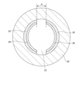
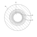
- FIG. 3 is a cross-sectional view of the piston rod taken along line III-III in FIG.
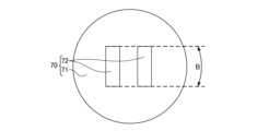
- FIG. 4A is a plan view of the connector.
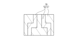
- FIG. 4B is a cross-sectional view of the connector, and corresponds to FIG.
- FIG. 5 is a cross-sectional view of a piston rod according to a first modified example of the present invention.
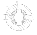
- FIG. 6 is a cross-sectional view of a piston rod according to a fourth modified example of the present invention.
- FIG. 7 is a cross-sectional view of a piston rod according to a fourth modified example of the present invention.
- the fluid pressure device according to this embodiment is a shock absorber 100 that is mounted on a vehicle or the like.
- the shock absorber 100 includes a cylinder tube 10, a piston rod 20 reciprocally disposed within the cylinder tube 10, a piston 30 connected to the piston rod 20 and slidably housed within the cylinder tube 10, a cylinder head 40 that closes one open end of the cylinder tube 10 and forms an extension side chamber 2 between the piston 30, a cylinder bottom 41 that closes the other open end of the cylinder tube 10 and forms a compression side chamber 3 between the piston 30, and an electromagnetic valve 60 provided on the piston rod 20.
- the cylinder tube 10 is formed in an annular shape.
- the inside of the cylinder tube 10 is divided by the piston 30 into an extension side chamber 2 as a rod side chamber and a compression side chamber 3 as a counter rod side chamber.
- a free piston 15 is slidably provided in the compression side chamber 3, and the free piston 15 separates the compression side chamber 3 into a liquid chamber 3a filled with hydraulic oil as a working fluid and an air chamber 3b filled with gas. Hydraulic oil is sealed in the extension side chamber 2.
- a working fluid such as a water-soluble substitute liquid may be used instead of oil as the hydraulic oil.
- One opening of the cylinder tube 10 (upper side in FIG. 1) is closed by the cylinder head 40, and the other opening (lower side in FIG. 1) is closed by the cylinder bottom 41.
- the piston rod 20 is slidably inserted through the cylinder head 40, which supports the piston rod 20.
- the cylinder head 40 is fastened to the cylinder tube 10 by multiple fastening members, etc.
- the cylinder tube 10, cylinder head 40, and piston 30 define the extension side chamber 2, and the cylinder tube 10, cylinder bottom 41, and piston 30 define the compression side chamber 3.
- the piston 30 faces the liquid chamber 3a of the compression side chamber 3.
- the piston rod 20 is made of a conductor such as metal.
- the piston rod 20 is made of a metal containing iron.
- the piston rod 20 has a large diameter portion 21, the tip of which faces the compression side chamber 3 and to which the piston 30 is connected, a small diameter portion 22 which slides on the inner circumferential surface of the cylinder head 40 and is formed with a smaller diameter than the large diameter portion 21, and a hollow portion 23 (see FIG. 2) which is formed by extending axially in the small diameter portion 22.
- the guide member 16 is connected to the large diameter portion 21 by a screw connection, and the guide member 16 is connected to the piston 30 by a screw connection. In this way, the piston 30 is connected to the piston rod 20 via the guide member 16.
- the large diameter portion 21 houses an electromagnetic valve 60, as described below.
- the hollow portion 23 is formed by penetrating the small diameter portion 22 of the piston rod 20 in the axial direction.
- a solenoid valve 60 is provided at the opening on the compression side chamber 3 side (the lower side in Figure 2) of the hollow portion 23, and a connector 70 is provided at the other opening. The details of the configuration inside the hollow portion 23 will be described later.
- the piston 30 is formed in a concave shape and is connected to the guide member 16.
- a seal member 35 is provided on the outer circumferential surface of the piston 30, and the seal member 35 blocks communication between the expansion side chamber 2 and the compression side chamber 3 through the space between the inner circumferential surface of the cylinder tube 10 and the outer circumferential surface of the piston 30.
- An annular seat member 17 is provided between the lower end of the guide member 16 and the piston 30 in FIG. 2.
- a first spool 18 that seats and unseats on the seat member 17 is provided inside the guide member 16, and an intermediate chamber 4 is formed in the first spool 18.
- An expansion side port 30a and a compression side port 30b that communicate between the intermediate chamber 4 and the compression side chamber 3 are formed at the bottom of the piston 30.
- An expansion side valve 31a is stacked below the expansion side port 30a and the compression side port 30b in FIG. 2, and a compression side valve 31b is stacked above the expansion side port 30a and the compression side port 30b.
- the expansion side port 30a opens into the intermediate chamber 4, and the pressure in the intermediate chamber 4 acts to open the expansion side valve 31a through the expansion side port 30a.
- the expansion side valve 31a opens due to the pressure in the intermediate chamber 4
- the hydraulic oil in the intermediate chamber 4 is led to the compression side chamber 3 through the expansion side port 30a.
- the compression side port 30b opens into the compression side chamber 3, and the pressure in the compression side chamber 3 acts to open the compression side valve 31b through the compression side port 30b.
- the compression side valve 31b opens due to the pressure in the compression side chamber 3, the hydraulic oil in the compression side chamber 3 is led to the intermediate chamber 4 through the compression side port 30b.
- the guide member 16 is formed with an opening 16a that opens into the extension-side chamber 2, and the pressure in the extension-side chamber 2 acts to lift the first spool 18 off the seating member 17.
- the hydraulic oil in the extension-side chamber 2 is guided to the intermediate chamber 4 through the gap between the first spool 18 and the seating member 17.
- the opening 16a of the guide member 16, the intermediate chamber 4, the expansion side port 30a, and the compression side port 30b form a main passage that connects the expansion side chamber 2 and the compression side chamber 3.
- a back pressure chamber 5 is formed between the inner peripheral surface of the guide member 16 and the outer peripheral surface of the first spool 18.
- the pressure in the back pressure chamber 5 acts so that the first spool 18 seats on the seating member 17.
- the first spool 18 is provided with a first passage 18b having a throttle 18a and reducing the pressure in the expansion side chamber 2, a second passage 18c that is provided downstream of the throttle 18a and communicates with the back pressure chamber 5, and a third passage 18d that only allows the flow of hydraulic oil from the intermediate chamber 4 toward the back pressure chamber 5, reducing the pressure in the intermediate chamber 4 and leading it to the back pressure chamber 5.
- An electromagnetic valve 60 is provided between the first passage 18b and the second passage 18c.
- the electromagnetic valve 60 has a second spool 61 that opens the second passage 18c by seating on and lifting off the seating portion 18e provided on the first spool 18, and a solenoid 65 that applies a downward thrust in FIG. 2 to the second spool 61.
- FIG. 2 shows a state in which the second spool 61 is lifted off the seating portion 18e.
- the second passage 18c is closed.
- the pressure of the back pressure chamber 5 acts through the second passage 18c to lift the second spool 61 off the seating portion 18e.
- the second passage 18c is opened.
- the solenoid valve 60 opens and closes as the second spool 61 seats and leaves the seating portion 18e.
- the solenoid 65 has a coil 66 housed in the large diameter portion 21 of the piston rod 20 and forming a magnetic field when a current is supplied to it, a plunger 67 that is provided inside the coil 66 and slidably housed in the large diameter portion 21 and to which a thrust force against the biasing force of the spring 69 is applied by the magnetic field formed by the coil 66, a rod 68 having one end connected to the plunger 67 and the other end abutting the second spool 61, and a spring 69 that is provided in the large diameter portion 21 and biases the second spool 61 via the plunger 67.
- the biasing force of the spring 69 acts on the second spool 61 via the plunger 67 and the rod 68 that is connected to the axis of the plunger 67.
- the spring 69 biases the second spool 61 so that the second spool 61 seats on the seating portion 18e of the first spool 18.
- the coil 66 is connected to a pair of conductive parts 26 (described later) formed in the hollow part 23 of the piston rod 20, and is electrically connected to an external control device (not shown) that serves as a power source via the conductive parts 26.
- the solenoid valve 60 is the part to be energized.
- the piston 30 moves upward in FIG. 2 within the cylinder tube 10 to compress the extension side chamber 2.
- the hydraulic oil in the extension side chamber 2 is guided to the back pressure chamber 5 through the first passage 18b, and the pressure in the back pressure chamber 5 increases.
- the second spool 61 (solenoid valve 60) opens, and the hydraulic oil in the back pressure chamber 5 is guided to the intermediate chamber 4 through the second passage 18c, space 19, and fourth passage 18f.
- the shock absorber 100 when the shock absorber 100 is extended, if the upward force acting on the first spool 18 due to the pressure in the expansion-side chamber 2 etc. exceeds the downward force acting on the first spool 18 due to the pressure in the back pressure chamber 5 etc., the first spool 18 moves upward. This creates a gap between the first spool 18 and the seating member 17, and the hydraulic oil in the expansion-side chamber 2 moves through the gap to the intermediate chamber 4, while the hydraulic oil in the intermediate chamber 4 opens the expansion-side valve 31a and is guided to the compression-side chamber 3. Therefore, the expansion-side valve 31a provides resistance to the flow of hydraulic oil moving from the expansion-side chamber 2 to the compression-side chamber 3.
- the piston 30 moves downward in FIG. 2 inside the cylinder tube 10 to compress the compression side chamber 3.
- the hydraulic oil in the compression side chamber 3 opens the compression side valve 31b and is guided to the intermediate chamber 4, and is also guided to the back pressure chamber 5 through the third passage 18d.
- the pressure in the space 19 is approximately the same as the pressure in the intermediate chamber 4 and is greater than the pressure in the back pressure chamber 5, so the second spool 61 is closed.
- the shock absorber 100 includes an electric current conducting part 26 provided in the hollow part 23 for conducting electricity to the solenoid valve 60, an insulating layer 25 formed on the inner peripheral surface of the hollow part 23, and a connector 70 provided in the hollow part 23 for electrically connecting the electric current conducting part 26 to a control device external to the piston rod 20.
- FIG. 3 is a cross-sectional view of the piston rod 20 taken along line III-III in FIG. 2, with the solenoid valve 60 omitted.
- the insulating layer 25 is provided integrally with the piston rod 20 on the inner circumferential surface of the hollow portion 23.
- the insulating layer 25 is formed by coating.
- the insulating layer 25 is an insulating layer formed by depositing an insulator through a chemical reaction with the inner circumferential surface of the piston rod 20, and is fixed to the inner circumferential surface of the piston rod 20 (hollow portion 23).
- the insulating layer 25 is formed of an autodeposition type paint. Note that the insulating layer 25 may be formed of a resin other than paint.
- the insulating layer 25 is provided in a pair, separated in the circumferential direction of the piston rod 20. Specifically, the pair of insulating layers 25 are provided opposite each other across the central axis of the piston rod 20.
- the conductive portion 26 is provided on the insulating layer 25.
- the conductive portion 26 is formed of a metal such as copper, and is provided integrally on the insulating layer 25 by plating.
- the insulating layer 25 insulates the conductive portion 26 from the piston rod 20 formed of a conductor.
- the conductive portions 26 are provided in pairs in the circumferential direction of the piston rod 20 so as not to be electrically connected to each other. Specifically, the pair of conductive portions 26 are provided opposite each other across the central axis of the piston rod 20, similar to the insulating layer 25. In other words, the pair of conductive portions 26 are separated in the circumferential direction by a non-conductive portion (space).
- the insulating layer 25 and the conductive portion 26 are provided over substantially the entire inner circumferential surface of the hollow portion 23, and are not provided in the areas corresponding to the solenoid valve 60 and the connector 70.
- FIG. 4A is a plan view of the connector 70 seen from above in FIG. 2, and FIG. 4B is a cross-sectional view of the connector 70 shown corresponding to FIG. 2.
- the connector 70 has a cylindrical main body 71 and a conductive portion 72 formed in the main body 71. A pair of conductive portions 72 are provided, extending in a stepped manner in the axial direction of the main body 71. As shown in FIG. 1, the connector 70 is provided on the piston rod 20 by inserting the main body 71 into the hollow portion 23.
- the connector 70 is provided in a circumferentially aligned manner so that one of the pair of conductive portions 72 contacts one of the pair of conductive portions 26 and the other of the pair of conductive portions 72 contacts the other of the pair of conductive portions 26, so that one conductive portion 72 does not contact both of the pair of conductive portions 26 to cause a short circuit.
- This allows an external control device of the piston rod 20 to be electrically connected to the solenoid valve 60 through the conductive portion 72 and the conductive portion 26, and allows the solenoid valve 60 to be controlled.
- the circumferential dimension B (see FIG. 4A) of the conductive portion 72 of the connector 70 is smaller than the circumferential dimension A (see FIG.
- a masking tool is attached to prevent the formation of the insulating layer 25 at a predetermined location of the piston rod 20, and then the insulating layer 25 is formed on the entire inner surface of the hollow portion 23. Then, the conductive portion 26 is formed on the insulating layer 25 by electroless plating and electrolytic plating. This forms the insulating layer 25 and the conductive portion 26 that are separated in the circumferential direction.
- a masking tool is attached to the outer peripheral surface and end surface of the piston rod 20 and the area on the inner peripheral surface of the hollow portion 23 where the insulating layer 25 and the conductive portion 26 are not to be formed, so that the insulating layer 25 and the conductive portion 26 are not to be formed in the corresponding locations.
- the piston rod 20 is placed in an autodeposition type paint.
- the autodeposition type paint examples include vinylidene chloride resin paint, acrylic resin paint, and epoxy resin paint.
- the chemical solution (paint) reacts with the iron of the piston rod 20 without electrolysis, and the paint (insulator) is autodeposited on the unmasked inner peripheral surface of the hollow portion 23, forming the insulating layer 25.
- the insulating layer 25 can be easily formed on the inner peripheral surface of the piston rod 20 by utilizing a chemical reaction with the metal piston rod 20.
- the insulating layer 25 is an insulating layer in which resin is precipitated by a chemical reaction with the inner peripheral surface of the piston rod 20.
- the piston rod 20 is placed in an etching tank to roughen the surface of the insulating layer 25 by etching, and then the piston rod 20 is placed in a catalyst tank to attach a catalyst such as palladium to the surface of the insulating layer 25. Then, the piston rod 20 is placed in a plating tank to perform electroless plating, and copper is precipitated on the surface of the insulating layer 25. Since the copper precipitation rate by electroless plating is slow, in this embodiment, copper is precipitated on the surface of the insulating layer 25 mainly by electrolytic plating.
- the piston rod 20 is washed with water, and copper is further precipitated on the surface of the insulating layer 25 by electrolytic plating. This shortens the time required to form the conductive portion 26.
- the conductive portion 26 is formed integrally with the insulating layer 25 and extends in the axial direction into the hollow portion 23.
- the conductive portion 26 may be formed only by electroless plating.
- the material deposited on the surface of the insulating layer 25 by electroless plating is not limited to copper, but may be other metals such as nickel.
- the insulating layer 25 and the conductive portion 26 are formed.
- masking is performed in advance to prevent the insulating layer 25 and the conductive portion 26 from being formed in the areas corresponding to the solenoid valve 60 and the connector 70, and to prevent the insulating layer 25 and the conductive portion 26 from being formed in parts of the circumference of the hollow portion 23 (two places in this embodiment).
- the insulating layer 25 and the conductive portion 26 as described above may also be formed by cutting the corresponding areas without masking.
- the conductive part 26 is provided integrally with the insulating layer 25 in the hollow part 23 of the piston rod 20, and the solenoid valve 60, which is the part to be energized, is energized via the conductive part 26. Therefore, unlike a configuration in which a cable-shaped or rod-shaped conductive part 26 is inserted into the hollow part 23, the conductive part 26 is provided integrally with the piston rod 20, and therefore, by simply assembling the piston rod 20, it is not necessary to insert or fix a cable-shaped or rod-shaped conductive part into the hollow part 23. This makes it easier to assemble the shock absorber 100.
- a pair of current-carrying parts 26 are provided in a circumferential direction of the piston rod 20 so that the current-carrying parts 26 are not electrically connected to each other, so that the solenoid valve 60 can be controlled by the control device. Therefore, in this embodiment, in the shock absorber 100 provided with multiple current-carrying parts 26 for electronically controlling the operation of the solenoid valve 60, as described above, the assembly work is easy.
- the conductive part 26 is provided integrally with the insulating layer 25 in the hollow part 23 of the piston rod 20. Therefore, since the conductive part 26 is provided integrally with the piston rod 20, it is possible to simply assemble the piston rod 20, eliminating the need to insert or fix a cable-shaped or rod-shaped conductive part into the hollow part 23, making it easier to assemble the shock absorber 100.
- the piston rod 20 is made of a conductor such as metal.
- the piston rod 20 may be made of an insulating material such as glass fiber reinforced plastic (GFRP).
- GFRP glass fiber reinforced plastic
- the entire piston rod 20 including the inner peripheral surface of the hollow portion 23 becomes the insulating layer 25.
- the piston rod 20 also functions as the insulating layer 25, and the work of forming the insulating layer 25 on the inner peripheral surface of the hollow portion 23 is not required. Even with this configuration, the same effects as those of the above embodiment are achieved.
- the insulating layer 25 is formed by placing the piston rod 20 made of a metal containing iron in an autodeposition type paint, and utilizing a chemical reaction in which the paint autodeposits.
- the method of forming the insulating layer 25 is not limited to this as long as it can be formed on the inner peripheral surface of the hollow portion 23.
- the insulating layer 25 may be formed by injection molding an insulating PTFE tube or the like, and then fixing the insulating layer 25 to the inner peripheral surface of the hollow portion 23 by blow molding in which high-pressure gas is blown into the tube.
- a chemical reaction such as that in this embodiment is not utilized, the piston rod 20 does not need to contain iron.
- the electrified part to be electrified is the solenoid valve 60 that is provided in the piston rod 20 and adjusts the damping force of the shock absorber 100.
- the present invention is not limited to this, and the solenoid valve 60 may be provided in the piston 30.
- the electrified part to be electrified is not limited to the solenoid valve 60, and may be, for example, a sensor that measures the position of the piston rod 20.
- the insulating layer 25 and the current-carrying portion 26 provided on the insulating layer 25 are each provided in two pieces, separated in the circumferential direction of the piston rod 20.
- the present invention is not limited to this, and three or more insulating layers 25 and current-carrying portions 26 may each be provided in a plurality of pieces, separated in the circumferential direction of the piston rod 20.
- another insulating layer 25 and current-carrying portion 26 may be laminated on the current-carrying portion 26.
- the insulating layer 25 and the current-carrying portion 26 may be provided without being separated in the circumferential direction of the piston rod 20. In other words, one insulating layer 25 and one current-carrying portion 26 may be provided around the entire circumferential direction. Also, in the embodiment shown in FIG. 6, the insulating layer 25 and the current-carrying portion 26 may be provided without being separated in the circumferential direction of the piston rod 20. In other words, multiple insulating layers 25 and current-carrying portions 26 may be provided by stacking them around the entire circumferential direction (see FIG. 7).
- ⁇ Modification 5> In the above embodiment, nothing is formed on the surface of the current-carrying portion 26, and the current-carrying portion 26 is exposed.
- an insulating coating may be formed on the surface of the current-carrying portion 26 by using an autodeposition type paint.
- the current-carrying portions 26 provided separately in the circumferential direction of the piston rod 20 can be brought close to each other without being electrically connected to each other. This allows the cross-sectional area of the current-carrying portion 26 to be increased, and also makes it easier to provide the multiple current-carrying portions 26 separately in the circumferential direction of the piston rod 20.
- the connection portions of the current-carrying portion 26 with the solenoid valve 60 and the connector 70 can be masked with masking tape or the like to prevent the coating from being formed on the connection portions.
- the connector 70 has the conductive portion 72 formed on the outer circumferential surface of the main body 71 and in contact with the current-carrying portion 26 for electrical connection.
- the connector 70 may have the conductive portion 72 formed on the outer circumferential surface of the main body 71 and in contact with the current-carrying portion 26 by being inserted into the inner circumferential surface of the current-carrying portion 26.
- the connector 70 may be provided only on the upper side of the hollow portion 23 in FIG. 2 to electrically connect the current-carrying portion 26 to an external control device, or may be provided only on the lower side of the hollow portion 23 in FIG. 2 to electrically connect the current-carrying portion 26 to the coil 66 of the solenoid 65, or may be provided on both the upper and lower sides of the hollow portion 23 in FIG. 2.
- the fluid pressure device is a shock absorber 100 mounted on a vehicle or the like.
- the fluid pressure device is not limited to this, and may be a hydraulic cylinder that is driven by hydraulic oil as a working fluid.
- a sensor or the like that is an electrically conductive part is provided on the piston rod or piston of the hydraulic cylinder, and an insulating layer 25 and an electrically conductive part 26 are formed in the hollow part of the piston rod. Even with this configuration, the same effects as those of the above embodiment can be achieved.
- the hollow portion 23 of the piston rod 20 may be connected to the extension side chamber 2 or the compression side chamber 3.
- the hollow portion 23 can be used as a flow path for supplying and discharging hydraulic oil to the extension side chamber 2 or the compression side chamber 3.
- the fluid pressure device (shock absorber 100) comprises a cylinder tube 10, a piston rod 20 reciprocally disposed within the cylinder tube 10, a piston 30 connected to the piston rod 20 and slidably disposed within the cylinder tube 10, dividing the interior of the cylinder tube 10 into a rod side chamber (extension side chamber 2) and an anti-rod side chamber (compression side chamber 3), a current-carrying part (solenoid valve 60) disposed within the cylinder tube 10 on the piston rod 20 or the piston 30, a current-carrying part 26 disposed in the hollow part 23 of the piston rod 20 for passing current through the current-carrying part, and an insulating layer 25 formed on the inner circumferential surface of the hollow part 23, the current-carrying part 26 being disposed on the insulating layer 25.
- the conductive part 26 is provided integrally with the insulating layer 25 in the hollow part 23 of the piston rod 20, and electricity is passed through the conductive part 26. Therefore, since the conductive part 26 is provided integrally with the piston rod 20, simply assembling the piston rod 20 eliminates the need to insert or fix a cable-shaped or rod-shaped conductive part into the hollow part 23. This makes it easier to assemble the fluid pressure device.
- the insulating layer 25 is also formed by coating.
- the piston rod 20 is made of metal, and the insulating layer 25 is formed by the deposition of an insulator through a chemical reaction with the inner surface of the piston rod 20.
- the insulating layer 25 is also formed from paint.
- the insulating layer 25 can be easily formed on the inner surface of the piston rod 20 by utilizing a chemical reaction with the metal piston rod 20.
- multiple current-carrying sections 26 are provided separately so that they are not electrically connected to each other.
- the multiple conductive parts 26 are arranged separately from each other in the circumferential direction of the piston rod 20.
Landscapes
- Engineering & Computer Science (AREA)
- General Engineering & Computer Science (AREA)
- Mechanical Engineering (AREA)
- Fluid-Damping Devices (AREA)
Abstract
ショックアブソーバ(100)は、シリンダチューブ(10)と、シリンダチューブ(10)内に往復動可能に設けられるピストンロッド(20)と、ピストンロッド(20)に連結されてシリンダチューブ(10)内に摺動自在に設けられるとともに、シリンダチューブ(10)内を伸側室(2)と圧側室(3)とに区画するピストン(30)と、シリンダチューブ(10)内においてピストンロッド(20)またはピストン(30)に設けられる通電対象の電磁弁(60)と、ピストンロッド(20)の中空部(23)に設けられ電磁弁(60)に通電するための通電部(26)と、中空部(23)の内周面に形成される絶縁層(25)と、を備え、通電部(26)は、絶縁層(25)上に一体に設けられる。
Description
本発明は、流体圧機器に関する。
JP2019-116940Aには、作動流体が封入されたシリンダと、シリンダ内に摺動可能に嵌装されたピストンと、一端がピストンに連結され他端がシリンダの外部に延出された中空のピストンロッドと、ピストンの移動に伴う作動流体の流れを制御することで減衰力特性を調整する減衰力調整機構と、を備える緩衝器が開示されている。減衰力調整機構は、ソレノイドを有してピストンに内蔵される。ピストンロッドの中空部には、導体を有しソレノイドへの通電に用いられる棒状のハーネスバーが挿入される。
JP2019-116940Aに記載のような緩衝器では、ピストンロッドの中空部に配線用の部材として棒状のハーネスバーが設けられる。そのため、中空部へのハーネスバーの挿入や固定といった取り回しが煩雑であり、緩衝器の組み立て作業に手間がかかる。
本発明は、ピストンロッドの中空部に通電部が設けられる流体圧機器において、組み立て作業を容易にすることを目的とする。
本発明のある態様によれば、流体圧機器であって、シリンダチューブと、前記シリンダチューブ内に往復動可能に設けられるピストンロッドと、前記ピストンロッドに連結されて前記シリンダチューブ内に摺動自在に設けられるとともに、前記シリンダチューブ内をロッド側室と反ロッド側室とに区画するピストンと、前記シリンダチューブ内において前記ピストンロッドまたは前記ピストンに設けられる通電対象の被通電部と、前記ピストンロッドの中空部に設けられ前記被通電部に通電するための通電部と、前記中空部の内周面に形成される絶縁層と、を備え、前記通電部は、前記絶縁層上に設けられる。
まず、図1を参照して、本発明の実施形態に係る流体圧機器について説明する。本実施形態に係る流体圧機器は、車両等に搭載されるショックアブソーバ100である。
図1に示すように、ショックアブソーバ100は、シリンダチューブ10と、シリンダチューブ10内に往復動可能に設けられるピストンロッド20と、ピストンロッド20に連結されシリンダチューブ10内に摺動自在に収容されるピストン30と、シリンダチューブ10の一方の開口端を閉塞するとともにピストン30との間に伸側室2を形成するシリンダヘッド40と、シリンダチューブ10の他方の開口端を閉塞するとともにピストン30との間に圧側室3を形成するシリンダボトム41と、ピストンロッド20に設けられる電磁弁60と、を備える。
シリンダチューブ10は、環状に形成される。シリンダチューブ10内は、ピストン30により、ロッド側室としての伸側室2と反ロッド側室としての圧側室3とに区画される。圧側室3にはフリーピストン15が摺動自在に設けられ、フリーピストン15により圧側室3が作動流体としての作動油が充填される液室3aとガスが封入される気室3bとに隔てられる。伸側室2には作動油が封入される。なお、作動油としてオイルの代わりに例えば水溶性代替液等の作動流体を用いてもよい。
シリンダチューブ10の一方(図1における上側)の開口部はシリンダヘッド40により閉塞され、他方(図1における下側)の開口部はシリンダボトム41により閉塞される。シリンダヘッド40は、ピストンロッド20が摺動自在に挿通され、ピストンロッド20を支持する。シリンダヘッド40は、複数の締結部材等により、シリンダチューブ10に締結される。シリンダチューブ10、シリンダヘッド40、及びピストン30によって伸側室2が区画され、シリンダチューブ10、シリンダボトム41、及びピストン30によって圧側室3が区画される。ピストン30は、圧側室3の液室3aに面する。
ピストンロッド20は、本実施形態では、金属等の導電体により形成される。具体的には、ピストンロッド20は、鉄を含む金属により形成される。ピストンロッド20は、圧側室3に面する先端部にピストン30が連結される大径部21と、シリンダヘッド40の内周面に摺動し大径部21よりも小径に形成される小径部22と、小径部22に軸方向に延びて形成される中空部23(図2参照)と、を有する。大径部21にはねじ結合によりガイド部材16が連結され、ガイド部材16はねじ結合によりピストン30に連結される。このように、ピストン30は、ガイド部材16を介してピストンロッド20に連結される。大径部21には、後述するように電磁弁60が収容される。
図2に示すように、中空部23は、ピストンロッド20の小径部22を軸方向に貫通して形成される。中空部23における圧側室3側(図2における下側)の開口部には電磁弁60が設けられ、他方の開口部にはコネクタ70が設けられる。中空部23内の構成の詳細については後述する。
図2に示すように、ピストン30は、凹状に形成され、ガイド部材16に連結される。ピストン30の外周面にはシール部材35が設けられ、シール部材35により、シリンダチューブ10の内周面とピストン30の外周面との間を通じた伸側室2と圧側室3との連通が遮断される。図2におけるガイド部材16の下端とピストン30の間には、環状の着座部材17が設けられる。ガイド部材16の内側には着座部材17に着座及び離座する第一スプール18が設けられ、第一スプール18内には中間室4が形成される。ピストン30の底部には、中間室4と圧側室3とを連通する伸側ポート30a及び圧側ポート30bが形成される。図2における伸側ポート30a及び圧側ポート30bの下側には伸側バルブ31aが積層され、伸側ポート30a及び圧側ポート30bの上側には圧側バルブ31bが積層される。
伸側ポート30aは中間室4に開口し、中間室4の圧力は伸側ポート30aを通じて伸側バルブ31aを開くように作用する。中間室4の圧力により伸側バルブ31aが開くと、中間室4の作動油が伸側ポート30aを通じて圧側室3に導かれる。また、圧側ポート30bは圧側室3に開口し、圧側室3の圧力は圧側ポート30bを通じて圧側バルブ31bを開くように作用する。圧側室3の圧力により圧側バルブ31bが開くと、圧側室3の作動油が圧側ポート30bを通じて中間室4に導かれる。
ガイド部材16には伸側室2に開口する開口部16aが形成され、伸側室2の圧力は第一スプール18が着座部材17から離座するように作用する。伸側室2の圧力により第一スプール18が着座部材17から離座すると、伸側室2の作動油が第一スプール18と着座部材17の間を通じて中間室4に導かれる。
このように、本実施形態のショックアブソーバ100では、ガイド部材16の開口部16a、中間室4、伸側ポート30a、及び圧側ポート30bにより、伸側室2と圧側室3を連通する主通路が形成される。
また、ガイド部材16の内周面と第一スプール18の外周面の間には、背圧室5が形成される。背圧室5の圧力は、第一スプール18が着座部材17に着座するように作用する。第一スプール18には、絞り18aが設けられ伸側室2の圧力を減圧する第一通路18bと、絞り18aよりも下流に設けられ背圧室5に連通する第二通路18cと、中間室4から背圧室5に向かう作動油の流れのみを許容し中間室4の圧力を減圧して背圧室5に導く第三通路18dと、が形成される。
第一通路18bと第二通路18cの間には、電磁弁60が設けられる。電磁弁60は、第一スプール18に設けられる着座部18eに着座及び離座して第二通路18cを開放する第二スプール61と、第二スプール61に図2における下向きの推力を作用させるソレノイド65と、を有する。なお、図2では、第二スプール61が着座部18eから離座した状態を示している。第二スプール61がソレノイド65の推力を受け着座部18eに着座すると、第二通路18cが閉じられる。これに対し、背圧室5の圧力は、第二通路18cを通じて第二スプール61が着座部18eから離座するように作用する。背圧室5の圧力が高まり第二スプール61が着座部18eから離座すると、第二通路18cが開放される。第二スプール61が着座部18eに着座及び離座することで、電磁弁60が開閉する。
電磁弁60が開くと、背圧室5の作動油が第二通路18cを通じて、第一スプール18とソレノイド65の間に形成される空間19に導かれる。空間19は、第一スプール18に形成される第四通路18fにより中間室4と連通する。よって、電磁弁60が開くと、背圧室5の作動油が第二通路18cを通じて空間19に導かれるとともに、空間19から第四通路18fを通じて中間室4に導かれる。これにより、中間室4と空間19の圧力が略同じとなる。
ソレノイド65は、ピストンロッド20の大径部21に収容され電流の供給によって磁界を形成するコイル66と、コイル66の内側に設けられ大径部21に摺動自在に収容され、コイル66が形成する磁界によりスプリング69の付勢力に抗する推力が付与されるプランジャ67と、プランジャ67に一端部側が連結され他端部が第二スプール61に当接するロッド68と、大径部21内に設けられプランジャ67を介して第二スプール61を付勢するスプリング69と、を有する。スプリング69の付勢力は、プランジャ67及びプランジャ67の軸心に連結されるロッド68を介して第二スプール61に作用する。つまり、スプリング69は、第二スプール61が第一スプール18の着座部18eに着座するように第二スプール61を付勢している。コイル66は、ピストンロッド20の中空部23に形成される後述する一対の通電部26にそれぞれ接続され、通電部26を介して電源である外部の制御装置(図示省略)と電気的に接続され通電される。本実施形態では、電磁弁60が、通電対象の被通電部である。
外部の制御装置からコイル66に電流が供給されると、プランジャ67には、スプリング69の付勢力に抗する推力が作用する。このため、プランジャ67及びロッド68を介して第二スプール61に作用するスプリング69の付勢力が小さくなり、結果として、第二スプール61を第一スプール18の着座部18eから離座させるために必要となる圧力は小さくなる。このように、コイル66への通電を制御し第二スプール61に作用するスプリング69の付勢力を変化させることによって、第二スプール61(電磁弁60)が開弁する設定圧を調整することができる。
ショックアブソーバ100の伸長時には、ピストン30がシリンダチューブ10内を図2における上側に移動して伸側室2を圧縮する。伸側室2の圧力が大きくなると、伸側室2の作動油が第一通路18bを通じて背圧室5に導かれ、背圧室5の圧力が大きくなる。背圧室5の圧力が第二スプール61の開弁圧に達すると第二スプール61(電磁弁60)が開き、背圧室5の作動油が第二通路18c、空間19、及び第四通路18fを通じて中間室4に導かれる。これにより、ショックアブソーバ100の伸長時には、背圧室5の圧力が電磁弁60の開弁圧を超えないように制御される。
また、ショックアブソーバ100の伸長時には、伸側室2の圧力等により第一スプール18に作用する上向きの力が、背圧室5の圧力等により第一スプール18に作用する下向きの力を上回ると、第一スプール18が上側に移動する。これにより、第一スプール18と着座部材17の間に隙間が生じ、伸側室2の作動油が当該隙間を通じて中間室4に移動するとともに、中間室4の作動油が伸側バルブ31aを開放し圧側室3に導かれる。よって、伸側バルブ31aが伸側室2から圧側室3に移動する作動油の流れに抵抗を与える。
さらに、ソレノイド65のコイル66への通電する電流が大きいほど、第二スプール61が第一スプール18の着座部18eに着座するように作用するプランジャ67の推力は小さくなる。このため、コイル66への通電する電流が大きいほど、電磁弁60の開弁圧は小さくなり、背圧室5の圧力は小さくなる。背圧室5の圧力は、第一スプール18が着座部材17に着座するように作用するため、コイル66への通電する電流を大きくし背圧室5の圧力を小さくすると、電磁弁60の開弁圧が小さくなり、ショックアブソーバ100の伸長時に生じる減衰力は小さくなる。このように、ソレノイド65で電磁弁60(第一スプール18)の開弁圧を調整することにより、ショックアブソーバ100の伸長時の減衰力が調整される。
一方で、ショックアブソーバ100の収縮時には、ピストン30がシリンダチューブ10内を図2における下側に移動して圧側室3を圧縮する。圧側室3の圧力が大きくなると、圧側室3の作動油が圧側バルブ31bを開いて中間室4へ導かれるとともに、第三通路18dを通じて背圧室5に導かれる。この状態では、空間19の圧力は、中間室4の圧力と略同じであり背圧室5の圧力よりも大きいため、第二スプール61は閉じた状態となる。また、中間室4の圧力等により第一スプール18に作用する上向きの力が、プランジャ67の推力等により第一スプール18に作用する下向きの力を上回ると、第一スプール18が上側に移動する。これにより、第一スプール18と着座部材17の間に隙間が生じ、中間室4の作動油が当該隙間を通じて伸側室2に移動する。このように、ショックアブソーバ100の収縮時には、圧側バルブ31b及び第一スプール18が開き、圧側室3から伸側室2に移動する作動油の流れに抵抗を与える。
また、ソレノイド65のコイル66への通電する電流が大きいほど、第二スプール61が第一スプール18の着座部18eに着座するように作用するプランジャ67の推力は小さくなる。このため、コイル66への通電する電流が大きいほど、電磁弁60の開弁圧は小さくなり、ショックアブソーバ100の収縮時の減衰力は小さくなる。このように、ソレノイド65で電磁弁60(第一スプール18)の開弁圧を調整することにより、ショックアブソーバ100の伸縮時の減衰力が調整される。
次に、ピストンロッド20の中空部23内の構成について詳しく説明する。
図2に示すように、ショックアブソーバ100は、中空部23に設けられ電磁弁60に通電するための通電部26と、中空部23の内周面に形成される絶縁層25と、中空部23に設けられ通電部26とピストンロッド20の外部の制御装置とを電気的に接続するコネクタ70と、を備える。
図3は図2のIII-III線に沿うピストンロッド20の断面図であり、電磁弁60を省略して示す。図3に示すように、絶縁層25は、中空部23の内周面にピストンロッド20と一体に設けられる。本実施形態では、絶縁層25は、コーティングにより形成される。具体的には、絶縁層25は、ピストンロッド20の内周面との化学反応により絶縁体が析出した絶縁層であり、ピストンロッド20(中空部23)の内周面に固着される。絶縁層25は、自己析出型の塗料で形成される。なお、絶縁層25は、塗料以外の樹脂により形成されてもよい。絶縁層25は、ピストンロッド20の周方向に分かれて一対設けられる。具体的には、一対の絶縁層25は、ピストンロッド20の中心軸を挟んで対向して設けられる。
通電部26は、絶縁層25上に設けられる。本実施形態では、通電部26は、銅等の金属で形成され、めっきにより絶縁層25上に一体に設けられる。絶縁層25によって、通電部26と導体により形成されるピストンロッド20が絶縁される。通電部26は、互いに電気的に接続しないように、ピストンロッド20の周方向に分かれて一対設けられる。具体的には、一対の通電部26は、絶縁層25と同様に、ピストンロッド20の中心軸を挟んで対向して設けられる。言い換えれば、一対の通電部26は、周方向において、非通電部(空間)により隔てられる。絶縁層25及び通電部26は、中空部23の内周面の略全体にわたって設けられ、電磁弁60及びコネクタ70に対応する領域には設けられない。
図4Aは図2における上側から見たコネクタ70の平面図であり、図4Bは図2に対応して示すコネクタ70の断面図である。コネクタ70は、円柱状の本体部71と、本体部71内に形成される導電部72と、を有する。導電部72は、本体部71の軸方向に段状に延びて一対設けられる。図1に示すように、コネクタ70は、本体部71が中空部23に挿入されてピストンロッド20に設けられる。コネクタ70は、一つの導電部72が一対の通電部26の両方に接触して短絡が生じないように、一対の導電部72の一方が一対の通電部26の一方に接触し、一対の導電部72の他方が一対の通電部26の他方に接触するように周方向に位置合わせして設けられる。これにより、ピストンロッド20の外部の制御装置が、導電部72及び通電部26を通じて電磁弁60と電気的に接続可能となり、電磁弁60の制御が可能となる。なお、コネクタ70は、導電部72の周方向の寸法B(図4A参照)が、一対の通電部26の間の周方向の寸法A(図3参照)よりも小さい場合には、一つの導電部72が一対の通電部26の両方に接触することがない。そのため、一対の導電部72が一対の通電部26の両方に接触しないことを避けてコネクタ70を取り付ければよく、コネクタ70の周方向の位置合わせに高い精度が要求されない。
次に、絶縁層25及び通電部26の形成方法について詳しく説明する。
本実施形態では、ピストンロッド20の所定の箇所に絶縁層25を形成しないようにマスキング用の治具を取り付けた後、中空部23の内周面全体に絶縁層25を形成し、その後、無電解めっき及び電解めっきにより絶縁層25上に通電部26を形成する。これにより、周方向に分かれた絶縁層25及び通電部26が形成される。
具体的には、まず、ピストンロッド20の外周面及び端面と、中空部23の内周面における絶縁層25及び通電部26を形成しない領域にマスキング用の治具を取り付け、当該箇所に絶縁層25及び通電部26が形成されないようにする。次に、自己析出型の塗料にピストンロッド20を入れる。自己析出型の塗料としては、例えば、塩化ビニリデン樹脂系塗料、アクリル樹脂系塗料、エポキシ樹脂系塗料を用いることができる。これにより、薬液(塗料)が無電解でピストンロッド20の鉄と反応して、中空部23のマスキングしていない内周面に塗料(絶縁体)が自己析出し、絶縁層25が形成される。このように、本実施形態では、金属製のピストンロッド20との化学反応を利用することにより、絶縁層25をピストンロッド20の内周面に容易に形成することができる。言い換えれば、絶縁層25は、ピストンロッド20の内周面との化学反応により樹脂が析出した絶縁層である。
次に、無電解めっきの前処理として、ピストンロッド20をエッチング槽に入れてエッチングにより絶縁層25の表面を粗くした後、ピストンロッド20を触媒槽に入れてパラジウム等の触媒を絶縁層25の表面に付着させる。そして、ピストンロッド20をめっき槽に入れて無電解めっきを行い、絶縁層25の表面に銅を析出させる。無電解めっきによる銅の析出速度は遅いため、本実施形態では、主に電解めっきにより絶縁層25の表面に銅を析出させる。より具体的には、上記のように無電解めっきで絶縁層25の表面に銅を薄く析出させて電解めっきができるようにした後、ピストンロッド20を水洗して、電解めっきによりさらに絶縁層25の表面に銅を析出させる。これにより、通電部26の形成時間が短縮される。その後、ピストンロッド20を乾燥させると、通電部26が絶縁層25と一体に中空部23に軸方向に伸びて形成される。なお、無電解めっきのみにより通電部26が形成されてもよい。また、無電解めっきで絶縁層25の表面に析出させるものは銅に限らず、ニッケル等の他の金属であってもよい。
このようにして、絶縁層25及び通電部26が形成される。本実施形態では、予めマスキングをすることにより、電磁弁60及びコネクタ70に対応する領域に絶縁層25及び通電部26が形成されないようにするとともに、中空部23の周方向の一部(本実施形態では二か所)に絶縁層25及び通電部26が形成されないようにしている。しかしながら、マスキングをせずに対応する領域を切削加工することで、上記のような絶縁層25及び通電部26を形成してもよい。
このように、ショックアブソーバ100では、ピストンロッド20の中空部23に通電部26が絶縁層25と一体に設けられ、通電部26を介して被通電部である電磁弁60が通電される。よって、中空部23にケーブル状や棒状の通電部26が挿通される構成とは異なり、通電部26がピストンロッド20と一体に設けられるため、ピストンロッド20を組み立てるだけで、中空部23へのケーブル状や棒状の通電部の挿入や固定の作業が不要となる。そのため、ショックアブソーバ100の組み立て作業が容易となる。
また、ショックアブソーバ100では、制御装置による電磁弁60の制御が可能なように、通電部26が、互いに電気的に接続しないように、ピストンロッド20の周方向に分かれて一対設けられる。そのため、本実施形態では、電磁弁60の動作を電子制御するための複数の通電部26が設けられるショックアブソーバ100において、上記のように、組み立て作業が容易となる。
以上の本実施形態によれば、以下に示す作用効果を奏する。
ショックアブソーバ100では、ピストンロッド20の中空部23に通電部26が絶縁層25と一体に設けられる。よって、通電部26がピストンロッド20と一体に設けられるため、ピストンロッド20を組み立てるだけで、中空部23へのケーブル状や棒状の通電部の挿入や固定の作業が不要となり、ショックアブソーバ100の組み立て作業が容易となる。
次に、上記実施形態の変形例について説明する。以下のような変形例も本発明の範囲内であり、以下の変形例と上記実施形態の構成とを組み合わせたり、以下の変形例同士を組み合わせたりすることも可能である。
<変形例1>
上記実施形態では、ピストンロッド20は、金属等の導体により形成される。これに限らず、図5に示すように、ピストンロッド20は、例えばガラス繊維強化プラスチック(GFRP)等の絶縁体により形成されてもよい。この構成では、中空部23の内周面を含むピストンロッド20全体が絶縁層25となる。言い換えれば、ピストンロッド20が絶縁層25としても機能し、中空部23の内周面に絶縁層25を形成する作業が不要となる。この構成であっても、上記実施形態と同様の効果を奏する。
上記実施形態では、ピストンロッド20は、金属等の導体により形成される。これに限らず、図5に示すように、ピストンロッド20は、例えばガラス繊維強化プラスチック(GFRP)等の絶縁体により形成されてもよい。この構成では、中空部23の内周面を含むピストンロッド20全体が絶縁層25となる。言い換えれば、ピストンロッド20が絶縁層25としても機能し、中空部23の内周面に絶縁層25を形成する作業が不要となる。この構成であっても、上記実施形態と同様の効果を奏する。
<変形例2>
上記実施形態では、絶縁層25は、自己析出型の塗料に鉄を含む金属により形成されるピストンロッド20を入れることで、塗料が自己析出する化学反応を利用することにより形成される。しかしながら、絶縁層25の形成方法は、中空部23の内周面に形成できればこれに限らない。例えば、絶縁性のPTFE製のチューブ等を射出成形した後、高圧の気体を管内に吹き込むブロー成形により、絶縁層25を中空部23の内周面に固着させて形成してもよい。また、本実施形態のような化学反応を利用しないのであれば、ピストンロッド20が鉄を含まなくてもよい。
上記実施形態では、絶縁層25は、自己析出型の塗料に鉄を含む金属により形成されるピストンロッド20を入れることで、塗料が自己析出する化学反応を利用することにより形成される。しかしながら、絶縁層25の形成方法は、中空部23の内周面に形成できればこれに限らない。例えば、絶縁性のPTFE製のチューブ等を射出成形した後、高圧の気体を管内に吹き込むブロー成形により、絶縁層25を中空部23の内周面に固着させて形成してもよい。また、本実施形態のような化学反応を利用しないのであれば、ピストンロッド20が鉄を含まなくてもよい。
<変形例3>
上記実施形態では、通電対象の被通電部は、ピストンロッド20に設けられショックアブソーバ100の減衰力を調整する電磁弁60である。これに限らず、電磁弁60は、ピストン30に設けられてもよい。また、通電対象の被通電部は電磁弁60に限らず、例えば、ピストンロッド20の位置等を測定するセンサであってもよい。
上記実施形態では、通電対象の被通電部は、ピストンロッド20に設けられショックアブソーバ100の減衰力を調整する電磁弁60である。これに限らず、電磁弁60は、ピストン30に設けられてもよい。また、通電対象の被通電部は電磁弁60に限らず、例えば、ピストンロッド20の位置等を測定するセンサであってもよい。
<変形例4>
上記実施形態では、絶縁層25及び絶縁層25の上に設けられる通電部26は、ピストンロッド20の周方向に分かれてそれぞれ二つ設けられる。これに限らず、絶縁層25及び通電部26は、ピストンロッド20の周方向に分かれてそれぞれ三つ以上の複数設けられてもよい。また、図6に示すように、通電部26の上にさらに別の絶縁層25及び通電部26が積層されて設けられてもよい。
上記実施形態では、絶縁層25及び絶縁層25の上に設けられる通電部26は、ピストンロッド20の周方向に分かれてそれぞれ二つ設けられる。これに限らず、絶縁層25及び通電部26は、ピストンロッド20の周方向に分かれてそれぞれ三つ以上の複数設けられてもよい。また、図6に示すように、通電部26の上にさらに別の絶縁層25及び通電部26が積層されて設けられてもよい。
さらに、図3に示す形態において、絶縁層25及び通電部26が、ピストンロッド20の周方向に分かれずに設けられてもよい。つまり、絶縁層25及び通電部26は、周方向全体にそれぞれ一つずつ設けられてもよい。また、図6に示す形態において、絶縁層25及び通電部26が、ピストンロッド20の周方向に分かれずに設けられてもよい。つまり、絶縁層25及び通電部26は、周方向全体に積層されて複数設けられてもよい(図7参照)。
<変形例5>
上記実施形態では、通電部26の表面には何も形成されず、通電部26がむき出しとなっている。これに限らず、通電部26の表面にさらに自己析出型の塗料により、通電部26の表面に絶縁体の皮膜が形成されてもよい。この構成では、ピストンロッド20の周方向に分かれて設けられる通電部26を、互いに電気的に接続されない状態で近づけることができる。これにより、通電部26の断面積を大きくできるとともに、複数の通電部26をピストンロッド20の周方向に分けて設けやすくできる。なお、皮膜を形成する際には、通電部26における電磁弁60及びコネクタ70との接続部をマスキングテープ等でマスクすることで、当該接続部に皮膜が形成されないようにすることができる。
上記実施形態では、通電部26の表面には何も形成されず、通電部26がむき出しとなっている。これに限らず、通電部26の表面にさらに自己析出型の塗料により、通電部26の表面に絶縁体の皮膜が形成されてもよい。この構成では、ピストンロッド20の周方向に分かれて設けられる通電部26を、互いに電気的に接続されない状態で近づけることができる。これにより、通電部26の断面積を大きくできるとともに、複数の通電部26をピストンロッド20の周方向に分けて設けやすくできる。なお、皮膜を形成する際には、通電部26における電磁弁60及びコネクタ70との接続部をマスキングテープ等でマスクすることで、当該接続部に皮膜が形成されないようにすることができる。
<変形例6>
上記実施形態では、コネクタ70は、導電部72が本体部71の外周面に露出せずに形成されて通電部26と接触し、電気的に接続される。これに限らず、コネクタ70は、導電部72が本体部71の外周面に露出して形成され、通電部26の内周面に挿入されて導電部72が通電部26と接触する構成であってもよい。また、コネクタ70は、中空部23の図2における上側にのみ設けられて通電部26と外部の制御装置とを電気的に接続する構成であっても、中空部23の図2における下側にのみ設けられて通電部26とソレノイド65のコイル66とを電気的に接続する構成であってもよく、中空部23の図2における上側と下側の両方に設けられてもよい。
上記実施形態では、コネクタ70は、導電部72が本体部71の外周面に露出せずに形成されて通電部26と接触し、電気的に接続される。これに限らず、コネクタ70は、導電部72が本体部71の外周面に露出して形成され、通電部26の内周面に挿入されて導電部72が通電部26と接触する構成であってもよい。また、コネクタ70は、中空部23の図2における上側にのみ設けられて通電部26と外部の制御装置とを電気的に接続する構成であっても、中空部23の図2における下側にのみ設けられて通電部26とソレノイド65のコイル66とを電気的に接続する構成であってもよく、中空部23の図2における上側と下側の両方に設けられてもよい。
<変形例7>
上記実施形態では、流体圧機器は、車両等に搭載されるショックアブソーバ100である。これに限らず、流体圧機器は、作動油を作動流体として駆動する油圧シリンダであってもよい。この構成では、油圧シリンダのピストンロッドまたはピストンに被通電部であるセンサ等が設けられ、ピストンロッドの中空部に絶縁層25及び通電部26が形成される。この構成であっても、上記実施形態と同様の効果を奏する。
上記実施形態では、流体圧機器は、車両等に搭載されるショックアブソーバ100である。これに限らず、流体圧機器は、作動油を作動流体として駆動する油圧シリンダであってもよい。この構成では、油圧シリンダのピストンロッドまたはピストンに被通電部であるセンサ等が設けられ、ピストンロッドの中空部に絶縁層25及び通電部26が形成される。この構成であっても、上記実施形態と同様の効果を奏する。
また、この場合には、ピストンロッド20の中空部23が、伸側室2または圧側室3と連通してもよい。中空部23が伸側室2または圧側室3と連通することにより、中空部23を伸側室2または圧側室3に作動油を給排する流路として使用することができる。
以上のように構成された本発明の実施形態の構成、作用、及び効果をまとめて説明する。
流体圧機器(ショックアブソーバ100)は、シリンダチューブ10と、シリンダチューブ10内に往復動可能に設けられるピストンロッド20と、ピストンロッド20に連結されてシリンダチューブ10内に摺動自在に設けられるとともに、シリンダチューブ10内をロッド側室(伸側室2)と反ロッド側室(圧側室3)とに区画するピストン30と、シリンダチューブ10内においてピストンロッド20またはピストン30に設けられる通電対象の被通電部(電磁弁60)と、ピストンロッド20の中空部23に設けられ被通電部に通電するための通電部26と、中空部23の内周面に形成される絶縁層25と、を備え、通電部26は、絶縁層25上に設けられる。
この構成では、ピストンロッド20の中空部23に通電部26が絶縁層25と一体に設けられ、通電部26を介して被通電部が通電される。よって、通電部26がピストンロッド20と一体に設けられるため、ピストンロッド20を組み立てるだけで、中空部23へのケーブル状や棒状の通電部の挿入や固定の作業が不要となる。そのため、流体圧機器の組み立て作業が容易となる。
また、絶縁層25は、コーティングにより形成される。
また、ピストンロッド20は、金属により形成され、絶縁層25は、ピストンロッド20の内周面との化学反応により絶縁体が析出した絶縁層25である。
また、絶縁層25は、塗料で形成される。
これらの構成では、金属製のピストンロッド20との化学反応を利用することにより、絶縁層25をピストンロッド20の内周面に容易に形成することができる。
また、通電部26は、互いに電気的に接続しないように分かれて複数設けられる。
また、複数の通電部26は、互いにピストンロッド20の周方向に分かれて設けられる。
これらの構成では、被通電部の動作を電子制御するための複数の通電部26が設けられる流体圧機器において、組み立て作業が容易となる。
以上、本発明の実施形態について説明したが、上記実施形態は本発明の適用例の一部を示したに過ぎず、本発明の技術的範囲を上記実施形態の具体的構成に限定する趣旨ではない。
本願は2023年5月18日に日本国特許庁に出願された特願2023-82145に基づく優先権を主張し、この出願の全ての内容は参照により本明細書に組み込まれる。
Claims (6)
- 流体圧機器であって、
シリンダチューブと、
前記シリンダチューブ内に往復動可能に設けられるピストンロッドと、
前記ピストンロッドに連結されて前記シリンダチューブ内に摺動自在に設けられるとともに、前記シリンダチューブ内をロッド側室と反ロッド側室とに区画するピストンと、
前記シリンダチューブ内において前記ピストンロッドまたは前記ピストンに設けられる通電対象の被通電部と、
前記ピストンロッドの中空部に設けられ前記被通電部に通電するための通電部と、
前記中空部の内周面に形成される絶縁層と、を備え、
前記通電部は、前記絶縁層上に設けられる流体圧機器。 - 請求項1に記載の流体圧機器であって、
前記絶縁層は、コーティングにより形成される流体圧機器。 - 請求項1に記載の流体圧機器であって、
前記ピストンロッドは、金属により形成され、
前記絶縁層は、前記ピストンロッドの前記内周面との化学反応により絶縁体が析出した絶縁層である流体圧機器。 - 請求項3に記載の流体圧機器であって、
前記絶縁層は、塗料で形成される流体圧機器。 - 請求項1に記載の流体圧機器であって、
前記通電部は、互いに電気的に接続しないように分かれて複数設けられる流体圧機器。 - 請求項5に記載の流体圧機器であって、
複数の前記通電部は、互いに前記ピストンロッドの周方向に分かれて設けられる流体圧機器。
Priority Applications (2)
| Application Number | Priority Date | Filing Date | Title |
|---|---|---|---|
| JP2025520529A JPWO2024237141A1 (ja) | 2023-05-18 | 2024-05-08 | |
| DE112024002147.6T DE112024002147T5 (de) | 2023-05-18 | 2024-05-08 | Fluiddruckapparat |
Applications Claiming Priority (2)
| Application Number | Priority Date | Filing Date | Title |
|---|---|---|---|
| JP2023082145 | 2023-05-18 | ||
| JP2023-082145 | 2023-05-18 |
Publications (1)
| Publication Number | Publication Date |
|---|---|
| WO2024237141A1 true WO2024237141A1 (ja) | 2024-11-21 |
Family
ID=93519118
Family Applications (1)
| Application Number | Title | Priority Date | Filing Date |
|---|---|---|---|
| PCT/JP2024/017075 Ceased WO2024237141A1 (ja) | 2023-05-18 | 2024-05-08 | 流体圧機器 |
Country Status (3)
| Country | Link |
|---|---|
| JP (1) | JPWO2024237141A1 (ja) |
| DE (1) | DE112024002147T5 (ja) |
| WO (1) | WO2024237141A1 (ja) |
Citations (4)
| Publication number | Priority date | Publication date | Assignee | Title |
|---|---|---|---|---|
| EP1219858A1 (en) * | 2000-12-29 | 2002-07-03 | Mando Corporation | Shock absorber using a hydraulic fluid and a magnetorheological fluid |
| JP2010255672A (ja) * | 2009-04-22 | 2010-11-11 | Honda Motor Co Ltd | ダンパ装置 |
| JP2019116940A (ja) * | 2017-12-27 | 2019-07-18 | 日立オートモティブシステムズ株式会社 | 緩衝器 |
| JP2020085118A (ja) * | 2018-11-26 | 2020-06-04 | Kyb株式会社 | 減衰バルブ |
-
2024
- 2024-05-08 DE DE112024002147.6T patent/DE112024002147T5/de active Pending
- 2024-05-08 JP JP2025520529A patent/JPWO2024237141A1/ja active Pending
- 2024-05-08 WO PCT/JP2024/017075 patent/WO2024237141A1/ja not_active Ceased
Patent Citations (4)
| Publication number | Priority date | Publication date | Assignee | Title |
|---|---|---|---|---|
| EP1219858A1 (en) * | 2000-12-29 | 2002-07-03 | Mando Corporation | Shock absorber using a hydraulic fluid and a magnetorheological fluid |
| JP2010255672A (ja) * | 2009-04-22 | 2010-11-11 | Honda Motor Co Ltd | ダンパ装置 |
| JP2019116940A (ja) * | 2017-12-27 | 2019-07-18 | 日立オートモティブシステムズ株式会社 | 緩衝器 |
| JP2020085118A (ja) * | 2018-11-26 | 2020-06-04 | Kyb株式会社 | 減衰バルブ |
Also Published As
| Publication number | Publication date |
|---|---|
| JPWO2024237141A1 (ja) | 2024-11-21 |
| DE112024002147T5 (de) | 2026-04-30 |
Similar Documents
| Publication | Publication Date | Title |
|---|---|---|
| JP2983633B2 (ja) | ツインパイプ衝撃吸収器 | |
| EP0161872A2 (en) | Improvements relating to shock absorbers | |
| KR101921400B1 (ko) | 이중/가변 게인 오일 펌프 제어 밸브 | |
| US9879746B2 (en) | Rod guide system and method with multiple solenoid valve cartridges and multiple pressure regulated valve assemblies | |
| DE102013103260A1 (de) | Kraftstoffeinspritzvorrichtung | |
| US20100044172A1 (en) | Damping force variable valve of shock absorber | |
| US20080093573A1 (en) | Electromagnetically Actuatable Valve | |
| US20150129378A1 (en) | Magnetorheological fluid damper | |
| WO1999009318A1 (en) | Improved fuel pump control valve assembly | |
| US20180094692A1 (en) | Damper and method of assembling damper | |
| NZ533352A (en) | Pilot operated pneumatic valve | |
| US5551540A (en) | Vibration damper and a vibration damper with a valve actuation device | |
| MXPA02006910A (es) | Valvula operada por solenoide, portadora de carga, y metodo de hacer la misma. | |
| CN101900214A (zh) | 用于分配流体的阀 | |
| WO2024237141A1 (ja) | 流体圧機器 | |
| CN101198817A (zh) | 用于控制流体流动的电磁致动器和方法 | |
| US5385455A (en) | Flow control valve | |
| US20230343499A1 (en) | Solenoid, solenoid valve, shock absorber, and method formanufacturing a solenoid | |
| CN1776214B (zh) | 带有柱塞电磁激励的燃料喷射器 | |
| US12049940B2 (en) | Shock absorber | |
| US20120187778A1 (en) | Actuator Which Can Be Actuated Electromagnetically, Particularly For An Adjustable Damping Valve Of A Vibration Damper | |
| KR20020029409A (ko) | 연료 분사 밸브 | |
| KR101335213B1 (ko) | 서보 밸브 | |
| JP6968017B2 (ja) | 緩衝器 | |
| US20250172190A1 (en) | Solenoid, damping force adjustment mechanism, and damping force adjustable shock absorber |
Legal Events
| Date | Code | Title | Description |
|---|---|---|---|
| 121 | Ep: the epo has been informed by wipo that ep was designated in this application |
Ref document number: 24807094 Country of ref document: EP Kind code of ref document: A1 |
|
| ENP | Entry into the national phase |
Ref document number: 2025520529 Country of ref document: JP Kind code of ref document: A |
|
| WWE | Wipo information: entry into national phase |
Ref document number: 2025520529 Country of ref document: JP |
|
| WWE | Wipo information: entry into national phase |
Ref document number: 112024002147 Country of ref document: DE |