WO2024236972A1 - 保持装置 - Google Patents
保持装置 Download PDFInfo
- Publication number
- WO2024236972A1 WO2024236972A1 PCT/JP2024/014898 JP2024014898W WO2024236972A1 WO 2024236972 A1 WO2024236972 A1 WO 2024236972A1 JP 2024014898 W JP2024014898 W JP 2024014898W WO 2024236972 A1 WO2024236972 A1 WO 2024236972A1
- Authority
- WO
- WIPO (PCT)
- Prior art keywords
- vehicle
- electromagnet
- smartphone
- holding
- unit
- Prior art date
- Legal status (The legal status is an assumption and is not a legal conclusion. Google has not performed a legal analysis and makes no representation as to the accuracy of the status listed.)
- Ceased
Links
Images



Classifications
-
- B—PERFORMING OPERATIONS; TRANSPORTING
- B60—VEHICLES IN GENERAL
- B60R—VEHICLES, VEHICLE FITTINGS, OR VEHICLE PARTS, NOT OTHERWISE PROVIDED FOR
- B60R11/00—Arrangements for holding or mounting articles, not otherwise provided for
- B60R11/02—Arrangements for holding or mounting articles, not otherwise provided for for radio sets, television sets, telephones, or the like; Arrangement of controls thereof
-
- B—PERFORMING OPERATIONS; TRANSPORTING
- B60—VEHICLES IN GENERAL
- B60K—ARRANGEMENT OR MOUNTING OF PROPULSION UNITS OR OF TRANSMISSIONS IN VEHICLES; ARRANGEMENT OR MOUNTING OF PLURAL DIVERSE PRIME-MOVERS IN VEHICLES; AUXILIARY DRIVES FOR VEHICLES; INSTRUMENTATION OR DASHBOARDS FOR VEHICLES; ARRANGEMENTS IN CONNECTION WITH COOLING, AIR INTAKE, GAS EXHAUST OR FUEL SUPPLY OF PROPULSION UNITS IN VEHICLES
- B60K35/00—Instruments specially adapted for vehicles; Arrangement of instruments in or on vehicles
- B60K35/20—Output arrangements, i.e. from vehicle to user, associated with vehicle functions or specially adapted therefor
- B60K35/21—Output arrangements, i.e. from vehicle to user, associated with vehicle functions or specially adapted therefor using visual output, e.g. blinking lights or matrix displays
- B60K35/22—Display screens
-
- B—PERFORMING OPERATIONS; TRANSPORTING
- B60—VEHICLES IN GENERAL
- B60K—ARRANGEMENT OR MOUNTING OF PROPULSION UNITS OR OF TRANSMISSIONS IN VEHICLES; ARRANGEMENT OR MOUNTING OF PLURAL DIVERSE PRIME-MOVERS IN VEHICLES; AUXILIARY DRIVES FOR VEHICLES; INSTRUMENTATION OR DASHBOARDS FOR VEHICLES; ARRANGEMENTS IN CONNECTION WITH COOLING, AIR INTAKE, GAS EXHAUST OR FUEL SUPPLY OF PROPULSION UNITS IN VEHICLES
- B60K35/00—Instruments specially adapted for vehicles; Arrangement of instruments in or on vehicles
- B60K35/80—Arrangements for controlling instruments
-
- B—PERFORMING OPERATIONS; TRANSPORTING
- B60—VEHICLES IN GENERAL
- B60K—ARRANGEMENT OR MOUNTING OF PROPULSION UNITS OR OF TRANSMISSIONS IN VEHICLES; ARRANGEMENT OR MOUNTING OF PLURAL DIVERSE PRIME-MOVERS IN VEHICLES; AUXILIARY DRIVES FOR VEHICLES; INSTRUMENTATION OR DASHBOARDS FOR VEHICLES; ARRANGEMENTS IN CONNECTION WITH COOLING, AIR INTAKE, GAS EXHAUST OR FUEL SUPPLY OF PROPULSION UNITS IN VEHICLES
- B60K35/00—Instruments specially adapted for vehicles; Arrangement of instruments in or on vehicles
- B60K35/80—Arrangements for controlling instruments
- B60K35/81—Arrangements for controlling instruments for controlling displays
-
- B—PERFORMING OPERATIONS; TRANSPORTING
- B60—VEHICLES IN GENERAL
- B60R—VEHICLES, VEHICLE FITTINGS, OR VEHICLE PARTS, NOT OTHERWISE PROVIDED FOR
- B60R11/00—Arrangements for holding or mounting articles, not otherwise provided for
- B60R11/02—Arrangements for holding or mounting articles, not otherwise provided for for radio sets, television sets, telephones, or the like; Arrangement of controls thereof
- B60R11/0229—Arrangements for holding or mounting articles, not otherwise provided for for radio sets, television sets, telephones, or the like; Arrangement of controls thereof for displays, e.g. cathodic tubes
- B60R11/0235—Arrangements for holding or mounting articles, not otherwise provided for for radio sets, television sets, telephones, or the like; Arrangement of controls thereof for displays, e.g. cathodic tubes of flat type, e.g. LCD
-
- B—PERFORMING OPERATIONS; TRANSPORTING
- B60—VEHICLES IN GENERAL
- B60R—VEHICLES, VEHICLE FITTINGS, OR VEHICLE PARTS, NOT OTHERWISE PROVIDED FOR
- B60R11/00—Arrangements for holding or mounting articles, not otherwise provided for
- B60R11/02—Arrangements for holding or mounting articles, not otherwise provided for for radio sets, television sets, telephones, or the like; Arrangement of controls thereof
- B60R11/0241—Arrangements for holding or mounting articles, not otherwise provided for for radio sets, television sets, telephones, or the like; Arrangement of controls thereof for telephones
-
- B—PERFORMING OPERATIONS; TRANSPORTING
- B60—VEHICLES IN GENERAL
- B60R—VEHICLES, VEHICLE FITTINGS, OR VEHICLE PARTS, NOT OTHERWISE PROVIDED FOR
- B60R11/00—Arrangements for holding or mounting articles, not otherwise provided for
- B60R11/02—Arrangements for holding or mounting articles, not otherwise provided for for radio sets, television sets, telephones, or the like; Arrangement of controls thereof
- B60R11/0252—Arrangements for holding or mounting articles, not otherwise provided for for radio sets, television sets, telephones, or the like; Arrangement of controls thereof for personal computers, e.g. laptops, notebooks
-
- F—MECHANICAL ENGINEERING; LIGHTING; HEATING; WEAPONS; BLASTING
- F16—ENGINEERING ELEMENTS AND UNITS; GENERAL MEASURES FOR PRODUCING AND MAINTAINING EFFECTIVE FUNCTIONING OF MACHINES OR INSTALLATIONS; THERMAL INSULATION IN GENERAL
- F16M—FRAMES, CASINGS OR BEDS OF ENGINES, MACHINES OR APPARATUS, NOT SPECIFIC TO ENGINES, MACHINES OR APPARATUS PROVIDED FOR ELSEWHERE; STANDS; SUPPORTS
- F16M11/00—Stands or trestles as supports for apparatus or articles placed thereon ; Stands for scientific apparatus such as gravitational force meters
- F16M11/02—Heads
- F16M11/04—Means for attachment of apparatus; Means allowing adjustment of the apparatus relatively to the stand
- F16M11/041—Allowing quick release of the apparatus
-
- F—MECHANICAL ENGINEERING; LIGHTING; HEATING; WEAPONS; BLASTING
- F16—ENGINEERING ELEMENTS AND UNITS; GENERAL MEASURES FOR PRODUCING AND MAINTAINING EFFECTIVE FUNCTIONING OF MACHINES OR INSTALLATIONS; THERMAL INSULATION IN GENERAL
- F16M—FRAMES, CASINGS OR BEDS OF ENGINES, MACHINES OR APPARATUS, NOT SPECIFIC TO ENGINES, MACHINES OR APPARATUS PROVIDED FOR ELSEWHERE; STANDS; SUPPORTS
- F16M11/00—Stands or trestles as supports for apparatus or articles placed thereon ; Stands for scientific apparatus such as gravitational force meters
- F16M11/02—Heads
- F16M11/04—Means for attachment of apparatus; Means allowing adjustment of the apparatus relatively to the stand
- F16M11/06—Means for attachment of apparatus; Means allowing adjustment of the apparatus relatively to the stand allowing pivoting
- F16M11/10—Means for attachment of apparatus; Means allowing adjustment of the apparatus relatively to the stand allowing pivoting around a horizontal axis
- F16M11/105—Means for attachment of apparatus; Means allowing adjustment of the apparatus relatively to the stand allowing pivoting around a horizontal axis the horizontal axis being the roll axis, e.g. for creating a landscape-portrait rotation
-
- F—MECHANICAL ENGINEERING; LIGHTING; HEATING; WEAPONS; BLASTING
- F16—ENGINEERING ELEMENTS AND UNITS; GENERAL MEASURES FOR PRODUCING AND MAINTAINING EFFECTIVE FUNCTIONING OF MACHINES OR INSTALLATIONS; THERMAL INSULATION IN GENERAL
- F16M—FRAMES, CASINGS OR BEDS OF ENGINES, MACHINES OR APPARATUS, NOT SPECIFIC TO ENGINES, MACHINES OR APPARATUS PROVIDED FOR ELSEWHERE; STANDS; SUPPORTS
- F16M11/00—Stands or trestles as supports for apparatus or articles placed thereon ; Stands for scientific apparatus such as gravitational force meters
- F16M11/02—Heads
- F16M11/18—Heads with mechanism for moving the apparatus relatively to the stand
-
- F—MECHANICAL ENGINEERING; LIGHTING; HEATING; WEAPONS; BLASTING
- F16—ENGINEERING ELEMENTS AND UNITS; GENERAL MEASURES FOR PRODUCING AND MAINTAINING EFFECTIVE FUNCTIONING OF MACHINES OR INSTALLATIONS; THERMAL INSULATION IN GENERAL
- F16M—FRAMES, CASINGS OR BEDS OF ENGINES, MACHINES OR APPARATUS, NOT SPECIFIC TO ENGINES, MACHINES OR APPARATUS PROVIDED FOR ELSEWHERE; STANDS; SUPPORTS
- F16M13/00—Other supports for positioning apparatus or articles; Means for steadying hand-held apparatus or articles
-
- F—MECHANICAL ENGINEERING; LIGHTING; HEATING; WEAPONS; BLASTING
- F16—ENGINEERING ELEMENTS AND UNITS; GENERAL MEASURES FOR PRODUCING AND MAINTAINING EFFECTIVE FUNCTIONING OF MACHINES OR INSTALLATIONS; THERMAL INSULATION IN GENERAL
- F16M—FRAMES, CASINGS OR BEDS OF ENGINES, MACHINES OR APPARATUS, NOT SPECIFIC TO ENGINES, MACHINES OR APPARATUS PROVIDED FOR ELSEWHERE; STANDS; SUPPORTS
- F16M13/00—Other supports for positioning apparatus or articles; Means for steadying hand-held apparatus or articles
- F16M13/02—Other supports for positioning apparatus or articles; Means for steadying hand-held apparatus or articles for supporting on, or attaching to, an object, e.g. tree, gate, window-frame, cycle
-
- G—PHYSICS
- G06—COMPUTING OR CALCULATING; COUNTING
- G06F—ELECTRIC DIGITAL DATA PROCESSING
- G06F1/00—Details not covered by groups G06F3/00 - G06F13/00 and G06F21/00
- G06F1/16—Constructional details or arrangements
- G06F1/1613—Constructional details or arrangements for portable computers
- G06F1/1632—External expansion units, e.g. docking stations
-
- H—ELECTRICITY
- H04—ELECTRIC COMMUNICATION TECHNIQUE
- H04M—TELEPHONIC COMMUNICATION
- H04M1/00—Substation equipment, e.g. for use by subscribers
- H04M1/02—Constructional features of telephone sets
- H04M1/11—Supports for sets, e.g. incorporating armrests
-
- B—PERFORMING OPERATIONS; TRANSPORTING
- B60—VEHICLES IN GENERAL
- B60R—VEHICLES, VEHICLE FITTINGS, OR VEHICLE PARTS, NOT OTHERWISE PROVIDED FOR
- B60R11/00—Arrangements for holding or mounting articles, not otherwise provided for
- B60R2011/0001—Arrangements for holding or mounting articles, not otherwise provided for characterised by position
- B60R2011/0003—Arrangements for holding or mounting articles, not otherwise provided for characterised by position inside the vehicle
- B60R2011/0005—Dashboard
-
- B—PERFORMING OPERATIONS; TRANSPORTING
- B60—VEHICLES IN GENERAL
- B60R—VEHICLES, VEHICLE FITTINGS, OR VEHICLE PARTS, NOT OTHERWISE PROVIDED FOR
- B60R11/00—Arrangements for holding or mounting articles, not otherwise provided for
- B60R2011/0042—Arrangements for holding or mounting articles, not otherwise provided for characterised by mounting means
- B60R2011/0049—Arrangements for holding or mounting articles, not otherwise provided for characterised by mounting means for non integrated articles
- B60R2011/005—Connection with the vehicle part
- B60R2011/0057—Connection with the vehicle part using magnetic means
-
- B—PERFORMING OPERATIONS; TRANSPORTING
- B60—VEHICLES IN GENERAL
- B60R—VEHICLES, VEHICLE FITTINGS, OR VEHICLE PARTS, NOT OTHERWISE PROVIDED FOR
- B60R11/00—Arrangements for holding or mounting articles, not otherwise provided for
- B60R2011/0042—Arrangements for holding or mounting articles, not otherwise provided for characterised by mounting means
- B60R2011/0049—Arrangements for holding or mounting articles, not otherwise provided for characterised by mounting means for non integrated articles
- B60R2011/0064—Connection with the article
- B60R2011/007—Connection with the article using magnetic means
-
- B—PERFORMING OPERATIONS; TRANSPORTING
- B60—VEHICLES IN GENERAL
- B60R—VEHICLES, VEHICLE FITTINGS, OR VEHICLE PARTS, NOT OTHERWISE PROVIDED FOR
- B60R11/00—Arrangements for holding or mounting articles, not otherwise provided for
- B60R2011/0042—Arrangements for holding or mounting articles, not otherwise provided for characterised by mounting means
- B60R2011/0049—Arrangements for holding or mounting articles, not otherwise provided for characterised by mounting means for non integrated articles
- B60R2011/0064—Connection with the article
- B60R2011/0071—Connection with the article using latches, clips, clamps, straps or the like
-
- B—PERFORMING OPERATIONS; TRANSPORTING
- B60—VEHICLES IN GENERAL
- B60R—VEHICLES, VEHICLE FITTINGS, OR VEHICLE PARTS, NOT OTHERWISE PROVIDED FOR
- B60R11/00—Arrangements for holding or mounting articles, not otherwise provided for
- B60R2011/0042—Arrangements for holding or mounting articles, not otherwise provided for characterised by mounting means
- B60R2011/0049—Arrangements for holding or mounting articles, not otherwise provided for characterised by mounting means for non integrated articles
- B60R2011/0064—Connection with the article
- B60R2011/0075—Connection with the article using a containment or docking space
-
- B—PERFORMING OPERATIONS; TRANSPORTING
- B60—VEHICLES IN GENERAL
- B60R—VEHICLES, VEHICLE FITTINGS, OR VEHICLE PARTS, NOT OTHERWISE PROVIDED FOR
- B60R11/00—Arrangements for holding or mounting articles, not otherwise provided for
- B60R2011/0042—Arrangements for holding or mounting articles, not otherwise provided for characterised by mounting means
- B60R2011/008—Adjustable or movable supports
- B60R2011/0082—Adjustable or movable supports collapsible, e.g. for storing after use
-
- B—PERFORMING OPERATIONS; TRANSPORTING
- B60—VEHICLES IN GENERAL
- B60R—VEHICLES, VEHICLE FITTINGS, OR VEHICLE PARTS, NOT OTHERWISE PROVIDED FOR
- B60R11/00—Arrangements for holding or mounting articles, not otherwise provided for
- B60R2011/0042—Arrangements for holding or mounting articles, not otherwise provided for characterised by mounting means
- B60R2011/008—Adjustable or movable supports
- B60R2011/0085—Adjustable or movable supports with adjustment by rotation in their operational position
-
- B—PERFORMING OPERATIONS; TRANSPORTING
- B60—VEHICLES IN GENERAL
- B60R—VEHICLES, VEHICLE FITTINGS, OR VEHICLE PARTS, NOT OTHERWISE PROVIDED FOR
- B60R11/00—Arrangements for holding or mounting articles, not otherwise provided for
- B60R2011/0042—Arrangements for holding or mounting articles, not otherwise provided for characterised by mounting means
- B60R2011/008—Adjustable or movable supports
- B60R2011/0085—Adjustable or movable supports with adjustment by rotation in their operational position
- B60R2011/0087—Adjustable or movable supports with adjustment by rotation in their operational position around two axes
-
- B—PERFORMING OPERATIONS; TRANSPORTING
- B60—VEHICLES IN GENERAL
- B60R—VEHICLES, VEHICLE FITTINGS, OR VEHICLE PARTS, NOT OTHERWISE PROVIDED FOR
- B60R11/00—Arrangements for holding or mounting articles, not otherwise provided for
- B60R2011/0042—Arrangements for holding or mounting articles, not otherwise provided for characterised by mounting means
- B60R2011/008—Adjustable or movable supports
- B60R2011/0092—Adjustable or movable supports with motorization
-
- B—PERFORMING OPERATIONS; TRANSPORTING
- B60—VEHICLES IN GENERAL
- B60R—VEHICLES, VEHICLE FITTINGS, OR VEHICLE PARTS, NOT OTHERWISE PROVIDED FOR
- B60R11/00—Arrangements for holding or mounting articles, not otherwise provided for
- B60R2011/0094—Arrangements for holding or mounting articles, not otherwise provided for characterised by means for covering after user, e.g. boxes, shutters or the like
Definitions
- the present invention relates to a holding device.
- Patent Document 1 A holder (holding device) for holding electronic devices with a display screen, such as smartphones, inside a vehicle is known (Patent Document 1).
- the holder in Patent Document 1 holds the electronic device with a clamping mechanism, and rotates a rotating plate to rotate the clamping structure and the electronic device.
- the holder in Patent Document 1 can also be rotated by user operation.
- the present invention was made in consideration of the above-mentioned circumstances, and its purpose is to provide a holding device that can rotate an electronic device according to the state of the vehicle without user operation.
- the holding device is characterized as follows.
- a holding device that is installed in a vehicle and holds an electronic device having a display screen, A holder for holding the electronic device; a rotation unit that rotates the holding unit in a direction around an axis that intersects with the display screen; A rotation control unit that controls the rotation of the rotating unit based on vehicle information indicating a state of the vehicle. It is a retaining device.
- the present invention provides a holding device that can rotate an electronic device according to the state of the vehicle without user operation.
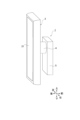
- FIG. 1 is an exploded perspective view showing a holding device according to a first embodiment of the present invention.
- FIG. 2 is a diagram showing an electrical configuration of the holding device shown in FIG.
- FIG. 3 is a flowchart showing a processing procedure of the vehicle-mounted ECU shown in FIG.
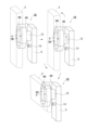
- FIG. 4 is a perspective view showing the holding device of FIG. 1 in which the smartphone is placed horizontally.
- FIG. 5 is a perspective view showing the holding device shown in FIG. 1 in which the smartphone is placed vertically.
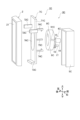
- FIG. 6 is an exploded perspective view showing a holding device according to the second embodiment of the present invention.
- FIG. 7 is an exploded perspective view showing a holding device according to the third embodiment of the present invention.
- FIG. 8 is a partial cross-sectional view of FIG.
- the holding device 1 shown in Figures 1 and 2 is a device that is installed on an instrument panel of a vehicle or the like and holds a smartphone 2.
- the holding device 1 includes a holding unit 3 that holds the smartphone 2, a rotating unit 4 that rotates the holding unit 3 around an axis along the front-rear direction, a holding unit 5 that holds the rotating unit 4, and an in-vehicle ECU (Electronic Control Unit) 6 (see Figure 2) as a rotation control unit that controls the rotation of the rotating unit 4 based on vehicle information indicating the state of the vehicle.
- a holding unit 3 that holds the smartphone 2
- a rotating unit 4 that rotates the holding unit 3 around an axis along the front-rear direction
- a holding unit 5 that holds the rotating unit 4
- an in-vehicle ECU (Electronic Control Unit) 6 see Figure 2 as a rotation control unit that controls the rotation of the rotating unit 4 based on vehicle information indicating the state of the vehicle.
- the smartphone 2 has a display screen 21 on the front side, and a ferromagnetic material such as iron that is attracted to a magnet and a magnet are built into the back side.
- the holding portion 3 has a permanent magnet 8 and an electromagnet 9 as a first electromagnet.
- the permanent magnet 8 is arranged in a disk shape that is arranged perpendicular to the front-to-rear direction, and is arranged to attract the ferromagnetic material or magnet built into the smartphone 2.
- the permanent magnet 8 has its south pole and north pole aligned along the front-to-rear direction.
- the permanent magnet 8 is arranged so that its magnetization direction is along the front-to-rear direction.
- the electromagnet 9 is arranged in a ring shape, with the permanent magnet 8 fitted and fixed in the center.
- the electromagnet 9 has a coil (not shown) wound around an axis along the front-to-rear direction, and like the permanent magnet 8, the north pole and south pole are arranged side by side along the front-to-rear direction.
- the electromagnet 9 is arranged so that its magnetization direction is along the front-to-rear direction.
- the rotating unit 4 includes a rotating shaft that rotates around an axis along the front-to-rear direction, and a motor (neither shown) that rotates the rotating shaft.
- the rear end of the rotating shaft is fixed to a permanent magnet 8, and when the rotating shaft is rotated by the motor, the permanent magnet 8 and the electromagnet 9 fixed to the permanent magnet 8 also rotate around an axis along the front-to-rear direction.
- the permanent magnet 8 rotates
- the smartphone 2 also rotates.
- the holding part 5 is fixed to the vehicle, for example to the instrument panel, and holds the rotating part 4.
- the on-board ECU 6 is connected to the coil of the electromagnet 9 and the motor of the rotating part 4, and controls the magnetic force of the electromagnet 9 and the rotation of the rotating part 4.
- the on-board ECU 6 is connected to a data communication unit 10 that enables communication with an in-vehicle network such as an in-vehicle LAN.
- the on-board ECU 6 receives vehicle information (e.g., shift information indicating the position of the shift lever, on/off information of the ignition switch, vehicle speed information, etc.) from the in-vehicle network via the data communication unit 10.
- vehicle information e.g., shift information indicating the position of the shift lever, on/off information of the ignition switch, vehicle speed information, etc.
- the in-vehicle ECU 6 is connected to a data communication unit 11 that enables communication with the smartphone 2.
- the in-vehicle ECU 6 receives electronic device information (model and type number information of the smartphone 2) and orientation information (whether the smartphone 2 is placed vertically or horizontally) from the smartphone 2 via the data communication unit 11.
- the procedure for using the holding device 1 configured as described above will be described.
- the user brings the back of the smartphone 2 close to the permanent magnet 8 or electromagnet 9.
- the smartphone 2 is attracted to the permanent magnet 8 or electromagnet 9 by the magnetic force of the permanent magnet 8 or electromagnet 9, and is held in the holding part 3.
- the in-vehicle ECU 6 starts processing and takes in shift information (S1). If the shift information indicates that the shift lever is in the R position, i.e., that the vehicle is in reverse (Y in S2), the in-vehicle ECU 6 controls the rotating unit 4 so that the smartphone 2 is placed horizontally as shown in FIG. 4 (S3). When the smartphone 2 is placed horizontally, the longitudinal direction of the display screen 21 is aligned with the left-right direction.
- the in-vehicle ECU 6 communicates with the smartphone 2 to obtain posture information, and if the posture information indicates that the smartphone is placed horizontally, the rotating unit 4 is not rotated, and if the posture information indicates that the smartphone is placed vertically, the rotating unit 4 is rotated to place the smartphone horizontally.
- the smartphone 2 communicates with the in-vehicle network to receive images from a camera mounted at the rear of the vehicle and displays the images on the display screen 21, thereby being used as a rear monitor. As shown in FIG. 4, it is easier to use the smartphone 2 as a rear monitor when the smartphone 2 is placed horizontally.
- the in-vehicle ECU 6 controls the rotation unit 4 so that the smartphone 2 is placed vertically as shown in FIG. 5 (S4).
- the smartphone 2 is placed vertically, the longitudinal direction of the display screen 21 is aligned with the up-down direction.
- the smartphone 2 can be placed vertically as in normal use.
- the in-vehicle ECU 6 communicates with the smartphone 2 to obtain attitude information, and if the attitude information indicates vertical, the rotation unit 4 is not rotated, and if the attitude information indicates horizontal, the rotation unit 4 is rotated to place the smartphone 2 vertically.
- the in-vehicle ECU 6 determines whether the removal angle (predetermined rotation position) of the smartphone 2 has been set by the user (S6).
- the user can use an app for the holding device 1 to communicate with the in-vehicle ECU 6 and set the removal angle to an angle at which the user can easily remove the smartphone 2.
- the removal angle is, for example, the angle between the up-down direction and the longitudinal direction of the display screen 21. If the removal angle has been set by the user (Y in S6), the in-vehicle ECU 6 rotates the rotating part 4 to the removal angle set by the user (S7) and then ends the process.
- the on-board ECU 6 functions as an electromagnet control unit and controls the electromagnet 9.
- the on-board ECU 6 takes in shift information and speed information in response to the ignition switch being turned on. If the shift information or speed information indicates that the vehicle is moving, the on-board ECU 6 controls the electromagnet 9 to increase the adhesive force of the smartphone 2 to the holding part 3, and if the information indicates that the vehicle is stopped, the on-board ECU 6 controls the electromagnet 9 to decrease the adhesive force of the smartphone 2 to the holding part 3.
- the smartphone 2 can be firmly attached and held in the holding section 3 while the vehicle is moving.
- the adhesive force of the smartphone 2 to the holding section 3 weakens when the vehicle is stopped, making it easier to remove the smartphone 2.
- the in-vehicle ECU 6 passes a current through the coil of the electromagnet 9 so that the magnetization direction of the electromagnet 9 is the same as that of the permanent magnet 8, and the amount of current through the coil while the vehicle is stopped is less than the amount of current through the coil while the vehicle is moving.
- the on-board ECU 6 may pass a current through the coil of the electromagnet 9 so that the magnetization direction of the electromagnet 9 is the same as that of the permanent magnet 8 while the vehicle is moving, and may reverse the direction of the current flowing through the coil while the vehicle is stopped so that the magnetization direction of the electromagnet 9 is opposite to that of the permanent magnet 8.
- the electromagnet 9 generates a magnetic force that repels the smartphone 2, further weakening the adhesive force of the smartphone 2 while the vehicle is stopped.
- the in-vehicle ECU 6 also receives model and model number information through communication with the smartphone 2. Since the weight of the smartphone 2 is known from the model and model number information, the in-vehicle ECU 6 may control the electromagnet 9 so that the adhesive force of the smartphone 2 increases as the weight increases.
- the in-vehicle ECU 6 controls the rotation of the rotating part 4 in response to vehicle information indicating the state of the vehicle, so that the smartphone 2 can be rotated in response to the state of the vehicle without any operation by the user.
- the smartphone 2 when the vehicle is moving backwards, the smartphone 2 is placed horizontally (the longitudinal direction of the display screen 21 is arranged along the left-right direction), making it easy to use as a rear monitor.
- the smartphone 2 When the vehicle is not moving backwards, the smartphone 2 is placed vertically (the longitudinal direction of the display screen 21 is arranged along the up-down direction), allowing the smartphone 2 to be arranged in the same way as during normal use.
- the in-vehicle ECU 6 controls the magnetic force of the electromagnet 9 so that the force of attraction of the smartphone 2 by the holding unit 3 is weakened while the vehicle is stopped, and controls the magnetic force of the electromagnet 9 so that the force of attraction of the smartphone 2 by the holding unit 3 is increased while the vehicle is moving.
- This increases the force of attraction of the smartphone 2 by the holding unit 3 while the vehicle is moving, and prevents the smartphone 2 from falling off the holding device 1.
- the force of attraction of the smartphone 2 by the holding unit 3 is weakened, and the smartphone 2 can be easily removed from the holding device 1.
- a holding device 1B according to a second embodiment will be described below with reference to Fig. 6.
- parts equivalent to those of the holding device 1 shown in Fig. 1 and the like already described in the first embodiment are designated by the same reference numerals, and detailed description thereof will be omitted.
- the holding device 1B includes a holding section 3B that holds a smartphone 2, a rotating section 4B, a holding section 5, and an on-board ECU 6.
- the holding section 3B includes a permanent magnet 8 and an electromagnet 9B.
- the positioning member 7 and the permanent magnet 8 are similar to those in the first embodiment, and therefore a detailed description thereof will be omitted here.
- the electromagnet 9B is arranged in a ring shape, with the permanent magnet 8 fitted and fixed in the center.
- the electromagnet 9B is wound with a coil (not shown) so that the magnetization direction is an axial direction along the front-rear direction, and the north poles and south poles are arranged alternately along the axial direction.
- the electromagnet 9B is provided with two north poles and two south poles.
- the rotating part 4B includes a rotating shaft 12 and an electromagnet 13 as a second electromagnet.
- the rotating shaft 12 is fixed to the permanent magnet 8, and is held by the holding part 5 so that it can rotate freely around the axis along the front-rear direction.
- Electromagnet 13 is held by holding portion 5 and is positioned opposite electromagnet 9B in the fore-and-aft direction. Electromagnet 13 has a coil (not shown) wound around an axis along the fore-and-aft direction, with north and south poles aligned along the fore-and-aft direction. On-board ECU 6 controls electromagnet 13 so that the magnetization direction alternates between the rear side being the north pole, the front side being the south pole, the rear side being the south pole, and the front side being the north pole.
- the on-board ECU 6 controls the electromagnet 9B so that the adhesive force of the smartphone 2 to the holding portion 3B is strong while the vehicle is moving, and controls the electromagnet 9B so that the adhesive force of the smartphone 2 to the holding portion 3B is weak while the vehicle is stopped. This allows the electromagnet 9B for holding the smartphone 2 to be reused to rotate the holding portion 3B.
- FIG. 7 a holding device 1C according to a third embodiment will be described below with reference to Figures 7 and 8.
- parts equivalent to those of the holding device 1 shown in Figure 1 and the like already described in the first embodiment are designated by the same reference numerals, and detailed description thereof will be omitted.
- the holding device 1C includes a holding section 3C that holds the smartphone 2, a rotating section 4C, a holding section 5C, and an on-board ECU 6.
- the holding section 3C includes a positioning member 7C, a permanent magnet 8C, and an electromagnet 9C.
- the positioning member 7C has a flat plate portion 71C, a pair of restricting plates 72C, 72C, a restricting plate 73C, a pair of locking arms 74C, 74C, and a positioning protrusion 75C.
- the flat plate portion 71C is formed in a rectangular shape, with a hole 76C in the center into which the rear end of the electromagnet 9C described below is fitted.
- the pair of restricting plates 72C, 72C are provided upright from both ends of the flat plate portion 71C in the short direction toward the front side, and restrict the movement of the smartphone 2 in the short direction.
- the restricting plate 73C is provided upright from one end of the flat plate portion 71C in the long direction toward the front side, and restricts the movement of the smartphone 2 in the long direction.
- the pair of locking arms 74C, 74C stand upright from the flat plate portion 71C toward the front, and have locking claws at their tips that lock with the electromagnet 9C in the front-rear direction.
- the pair of locking arms 74C, 74C are arranged side by side along the longitudinal direction of the flat plate portion 71C.
- the positioning protrusion 75C protrudes toward the front from the flat plate portion 71C.
- the permanent magnet 8C is disk-shaped and, unlike the first embodiment, does not have a positioning hole.
- the electromagnet 9C is ring-shaped like the first embodiment, with the permanent magnet 8C fixed to its center.
- a positioning groove 91C is provided on the side of the electromagnet 9C along the front-rear direction into which the positioning protrusion 75C is fitted.
- the rotating unit 4C has a rotating shaft 14, gears 15, gears 16, a rotating shaft 17, and a motor (not shown).
- the rotating shaft 14 is held by the holding unit 5C so as to be rotatable around an axis along the front-to-rear direction, and its rear end is fixed to a permanent magnet 8C.
- the gear 15 is attached to the rotating shaft 14.
- the gear 16 is attached to the rotating shaft 17 so as to mesh with the gear 15.
- the rotating shaft 17 is rotated by the motor around an axis along the front-to-rear direction. When the rotating shaft 17 is rotated by the motor, the rotational force is transmitted to the rotating shaft 17 via the gears 15 and 16, causing the permanent magnet 8C to rotate.
- the present invention is not limited to the above-described embodiment, and can be modified, improved, etc. as appropriate.
- the material, shape, dimensions, number, location, etc. of each component in the above-described embodiment are arbitrary as long as they can achieve the present invention, and are not limited.
- a smartphone 2 has been given as an example of an electronic device, but the present invention is not limited to this.
- the electronic device may be any device that has a display screen, such as a tablet.
- the holders 3, 3B, and 3C attract and hold the smartphone 2 by the magnetic force of the permanent magnets 8 and 8C, but this is not limited to the above.
- the holders may have any structure capable of holding the smartphone 2, and may, for example, hold the smartphone 2 by pinching both sides of the smartphone 2 in the short direction.
- the rotation control of the smartphone 2 is not limited to the above-described embodiment.
- the in-vehicle ECU 6 may control the rotation of the rotating unit 4 so that the smartphone 2 is oriented vertically when going straight and horizontally when turning right or left.
- the in-vehicle ECU 6 communicates with the smartphone 2 to obtain navigation information, and when the navigation information indicates a straight-ahead direction, controls the rotating unit 4 so that the smartphone 2 is oriented vertically.
- the in-vehicle ECU 6 determines that it is time to turn right or left and controls the rotation unit 4 so that the smartphone 2 is placed horizontally. At this time, the rotation angle and rotation speed of the smartphone 2 may be controlled in conjunction with information from a steering angle sensor. By placing the smartphone horizontally when turning right or left, map information of the destination after the turn can be confirmed, providing the user with more information.
- the in-vehicle ECU 6 When the right or left turn is completed, the in-vehicle ECU 6 returns the smartphone 2 to the vertical position. Completion of the right or left turn can be determined based on vehicle position information and information from the steering angle sensor. When returning the smartphone 2 from the horizontal position to the vertical position, the in-vehicle ECU 6 may also control the rotation angle and rotation speed of the smartphone 2 in conjunction with information from the steering angle sensor.
- the smartphone 2 may also be rotated according to the vehicle state, such as the vehicle's position information and speed, and the type of application.
- the screen orientation that is easiest to view varies depending on the application.
- the in-vehicle ECU 6 places the smartphone 2 vertically.
- the in-vehicle ECU 6 places the smartphone 2 horizontally.
- the in-vehicle ECU 6 may place the smartphone 2 vertically to make it difficult for the user to watch videos.
- the in-vehicle ECU 6 places the smartphone 2 vertically. Then, when it determines that the delivery destination is approaching, the smartphone 2 switches to a delivery management app. At this time, the in-vehicle ECU 6 places the smartphone 2 horizontally. When it determines that the vehicle has stopped to deliver a package to the delivery destination based on speed information and vehicle ignition information, the in-vehicle ECU 6 places the smartphone 2 vertically so that it is easier to remove. There are multiple ways to switch applications, such as by touch operation on the smartphone 2 or by switching between voice operations.
- the smartphone 2 may be placed vertically or horizontally depending on the type of application being used. For example, when a navigation application, a map application, an SNS application, or a telephone application is being used, the smartphone 2 is placed vertically. Moreover, when a video playback application, an image/video shooting application, a data management application (delivery management), a game, or the like is being used, the smartphone 2 is placed horizontally.
- a holding device (1, 1B, 1C) for holding an electronic device (2) having a display screen (21) installed in a vehicle comprising: A holding portion (3, 3B, 3C) for holding the electronic device (2); a rotating unit (4, 4B, 4C) that rotates the holding unit (3, 3B, 3C) in a direction around an axis that intersects with the display screen (21); A rotation control unit (6) that controls the rotation of the rotating unit (4, 4B, 4C) based on vehicle information indicating a state of the vehicle. Holding device (1, 1B, 1C).
- the rotation control unit (6) controls the rotation of the rotation units (4, 4B, 4C) according to the state of the vehicle, so that the electronic device (2) can be rotated according to the state of the vehicle without user operation.
- the electronic device (2) when the vehicle is moving backwards, the electronic device (2) is placed horizontally (the longitudinal direction of the display screen (21) is aligned along the left-right direction), making it easy to use as a rear monitor.
- the electronic device (2) When the vehicle is not moving backwards, the electronic device (2) is placed vertically (the longitudinal direction of the display screen (21) is aligned along the up-down direction), allowing the electronic device (2) to be positioned in the same way as during normal use.
- the rotation control unit (6) rotates the rotating unit (4, 4B, 4C) to a predetermined rotation position when the vehicle information indicates that an ignition switch of the vehicle is off, A setting unit (6) that sets the predetermined rotation position through communication with the electronic device (2). Holding device (1, 1B, 1C).
- the electronic device (2) when the ignition switch is turned off and the electronic device (2) is to be removed from the holding device (1, 1B, 1C), the electronic device (2) automatically rotates to a predetermined rotation position set by the user, making it easy to remove the electronic device (2).
- the holding portion (3, 3B, 3C) has a permanent magnet (8, 8C) and a first electromagnet (9, 9B, 9C) that attract the electronic device (2)
- the holding device (1, 1B, 1C) further includes an electromagnet control unit (6) that controls the magnetic force of the first electromagnet (9, 9B, 9C) so that the adhesive force of the holding unit (3, 3B, 3C) to the electronic device (2) is weakened when the vehicle information indicates that the vehicle is stopped, and controls the magnetic force of the first electromagnet (9, 9B, 9C) so that the adhesive force of the holding unit (3, 3B, 3C) to the electronic device (2) is increased when the vehicle information indicates that the vehicle is running.
- the force of suction of the electronic device (2) by the holding portion (3, 3B, 3C) increases while the vehicle is moving, and the electronic device (2) can be prevented from falling off the holding device (1, 1B, 1C).
- the force of suction of the electronic device (2) by the holding portion (3, 3B, 3C) weakens, and the electronic device (2) can be easily removed from the holding device (1, 1B, 1C).
- the first electromagnet (9B) is magnetized along a direction around the axis
- the rotating portion (4B) has a second electromagnet (13) facing the first electromagnet (9B) in an axial direction intersecting with the display screen (21),
- the rotation control unit (6) controls the magnetic force of the second electromagnet (13) to control the rotation of the rotating unit (4B). Holding device (1B).
- the first electromagnet (9, 9B, 9C) for holding the electronic device (2) can be used to rotate the holding part (3B).
- the present invention provides a holding device that can rotate an electronic device according to the state of the vehicle without user operation.
- the present invention which has this effect, is useful in relation to holding devices.
Landscapes
- Engineering & Computer Science (AREA)
- Mechanical Engineering (AREA)
- General Engineering & Computer Science (AREA)
- Transportation (AREA)
- Chemical & Material Sciences (AREA)
- Combustion & Propulsion (AREA)
- Theoretical Computer Science (AREA)
- Signal Processing (AREA)
- Computer Hardware Design (AREA)
- Human Computer Interaction (AREA)
- Physics & Mathematics (AREA)
- General Physics & Mathematics (AREA)
- Fittings On The Vehicle Exterior For Carrying Loads, And Devices For Holding Or Mounting Articles (AREA)
- Telephone Set Structure (AREA)
Abstract
Description
車内に設置され、表示画面を有する電子機器を保持する保持装置であって、
前記電子機器を保持する保持部と、
前記表示画面に交差する軸回り方向に前記保持部を回転させる回転部と、
車両の状態を示す車両情報に基づいて前記回転部の回転を制御する回転制御部と、を備えた、
保持装置であること。
図1及び図2に示す保持装置1は、車両のインストルメントパネルなどに設置され、スマートフォン2を保持する装置である。図1に示すように、保持装置1は、スマートフォン2を保持する保持部3と、前後方向に沿った軸回りに保持部3を回転させる回転部4と、回転部4を保持する保持部5と、車両の状態を示す車両情報に基づいて回転部4の回転を制御する回転制御部としての車載ECU(Electronic Control Unit)6(図2参照)と、を備えている。
次に、第2実施形態の保持装置1Bについて図6を参照して以下説明する。図6において、上述した第1実施形態で既に説明した図1等に示す保持装置1と同等の部分には同一符号を付してその詳細な説明を省略する。
次に、第3実施形態の保持装置1Cについて図7及び図8を参照して以下説明する。図7及び図8において、上述した第1実施形態で既に説明した図1等に示す保持装置1と同等の部分には同一符号を付してその詳細な説明を省略する。
[1]
車内に設置され、表示画面(21)を有する電子機器(2)を保持する保持装置(1,1B,1C)であって、
前記電子機器(2)を保持する保持部(3,3B,3C)と、
前記表示画面(21)に交差する軸回り方向に前記保持部(3,3B,3C)を回転させる回転部(4,4B,4C)と、
車両の状態を示す車両情報に基づいて前記回転部(4,4B,4C)の回転を制御する回転制御部(6)と、を備えた、
保持装置(1,1B,1C)。
[1]に記載の保持装置(1,1B,1C)において、
前記回転制御部(6)は、前記車両情報が車両後進を示す場合、前記表示画面(21)の長手方向が左右方向に沿うように前記回転部(4,4B,4C)を回転させ、前記車両情報が前記車両後進を示していない場合、前記表示画面(21)の長手方向が上下方向に沿うように前記回転部(4,4B,4C)を回転させる、
保持装置(1,1B,1C)。
[1]に記載の保持装置(1,1B,1C)において、
前記回転制御部(6)は、前記車両情報が前記車両のイグニッションスイッチがオフを示す場合、予め定めた回転位置まで前記回転部(4,4B,4C)を回転させ、
前記電子機器(2)との通信により予め定めた前記回転位置を設定する設定部(6)を有する、
保持装置(1,1B,1C)。
[1]に記載の保持装置(1,1B,1C)において、
前記保持部(3,3B,3C)は、前記電子機器(2)を吸着する永久磁石(8,8C)及び第1電磁石(9,9B,9C)を有し、
前記車両情報が車両停止中を示す場合、前記保持部(3,3B,3C)による前記電子機器(2)の吸着力が弱まるように前記第1電磁石(9,9B,9C)の磁力を制御し、前記車両情報が車両走行中を示す場合、前記保持部(3,3B,3C)による前記電子機器(2)の吸着力が高まるように前記第1電磁石(9,9B,9C)の磁力を制御する電磁石制御部(6)をさらに備えた
保持装置(1,1B,1C)。
[4]に記載の保持装置(1B)において、
前記第1電磁石(9B)は、前記軸回り方向に沿って磁化され、
前記回転部(4B)は、前記第1電磁石(9B)と前記表示画面(21)に交差する軸方向に対向する第2電磁石(13)を有し、
前記回転制御部(6)は、前記第2電磁石(13)の磁力を制御して、前記回転部(4B)の回転を制御する、
保持装置(1B)。
2 スマートフォン(電子機器)
3,3B,3C 保持部
4,4B,4C 回転部
6 車載ECU(回転制御部、設定部、電磁石制御部)
8,8C 永久磁石
9,9B,9C 電磁石(第1電磁石)
13 電磁石(第2電磁石)
21 表示画面
Claims (5)
- 車内に設置され、表示画面を有する電子機器を保持する保持装置であって、
前記電子機器を保持する保持部と、
前記表示画面に交差する軸回り方向に前記保持部を回転させる回転部と、
車両の状態を示す車両情報に基づいて前記回転部の回転を制御する回転制御部と、を備えた、
保持装置。 - 請求項1に記載の保持装置において、
前記回転制御部は、前記車両情報が車両後進を示す場合、前記表示画面の長手方向が左右方向に沿うように前記回転部を回転させ、前記車両情報が前記車両後進を示していない場合、前記表示画面の長手方向が上下方向に沿うように前記回転部を回転させる、
保持装置。 - 請求項1に記載の保持装置において、
前記回転制御部は、前記車両情報が前記車両のイグニッションスイッチがオフを示す場合、予め定めた回転位置まで前記回転部を回転させ、
前記電子機器との通信により予め定めた前記回転位置を設定する設定部を有する、
保持装置。 - 請求項1に記載の保持装置において、
前記保持部は、前記電子機器を吸着する永久磁石及び第1電磁石を有し、
前記車両情報が車両停止中を示す場合、前記保持部による前記電子機器の吸着力が弱まるように前記第1電磁石の磁力を制御し、前記車両情報が車両走行中を示す場合、前記保持部による前記電子機器の吸着力が高まるように前記第1電磁石の磁力を制御する電磁石制御部をさらに備えた
保持装置。 - 請求項4に記載の保持装置において、
前記第1電磁石は、前記軸回り方向に沿って磁化され、
前記回転部は、前記第1電磁石と前記表示画面に交差する軸方向に対向する第2電磁石を有し、
前記回転制御部は、前記第2電磁石の磁力を制御して、前記回転部の回転を制御する、
保持装置。
Priority Applications (2)
| Application Number | Priority Date | Filing Date | Title |
|---|---|---|---|
| CN202480025508.9A CN121079227A (zh) | 2023-05-15 | 2024-04-12 | 保持设备 |
| EP24806926.2A EP4714749A1 (en) | 2023-05-15 | 2024-04-12 | Holding device |
Applications Claiming Priority (2)
| Application Number | Priority Date | Filing Date | Title |
|---|---|---|---|
| JP2023-080189 | 2023-05-15 | ||
| JP2023080189A JP7680494B2 (ja) | 2023-05-15 | 2023-05-15 | 保持装置 |
Publications (1)
| Publication Number | Publication Date |
|---|---|
| WO2024236972A1 true WO2024236972A1 (ja) | 2024-11-21 |
Family
ID=93518948
Family Applications (1)
| Application Number | Title | Priority Date | Filing Date |
|---|---|---|---|
| PCT/JP2024/014898 Ceased WO2024236972A1 (ja) | 2023-05-15 | 2024-04-12 | 保持装置 |
Country Status (4)
| Country | Link |
|---|---|
| EP (1) | EP4714749A1 (ja) |
| JP (1) | JP7680494B2 (ja) |
| CN (1) | CN121079227A (ja) |
| WO (1) | WO2024236972A1 (ja) |
Citations (8)
| Publication number | Priority date | Publication date | Assignee | Title |
|---|---|---|---|---|
| WO2010071053A1 (ja) * | 2008-12-18 | 2010-06-24 | アイシン精機株式会社 | 表示装置 |
| KR101700339B1 (ko) * | 2015-11-16 | 2017-01-26 | 주식회사 핀크래프트엔지니어링 | 무선 충전 시스템에 적용된 차량용 거치대 |
| US20180011551A1 (en) * | 2016-07-06 | 2018-01-11 | Volvo Car Corporation | Multi mode screen device for a vehicle and a method for providing a multi mode screen device in a vehicle |
| KR20180002287U (ko) * | 2017-01-18 | 2018-07-26 | 손성현 | 차량용 스마트폰 거치대 |
| WO2020158279A1 (ja) * | 2019-02-01 | 2020-08-06 | 株式会社デンソー | 表示装置 |
| JP2022006530A (ja) | 2020-06-24 | 2022-01-13 | 株式会社コムテック | ホルダ |
| WO2022232562A1 (en) * | 2021-04-30 | 2022-11-03 | Fisker Inc. | Rotating vehicle center information display with stationary buttons and touch bar |
| JP2023080189A (ja) | 2018-04-19 | 2023-06-08 | 株式会社幸和製作所 | 折り畳み椅子 |
-
2023
- 2023-05-15 JP JP2023080189A patent/JP7680494B2/ja active Active
-
2024
- 2024-04-12 WO PCT/JP2024/014898 patent/WO2024236972A1/ja not_active Ceased
- 2024-04-12 EP EP24806926.2A patent/EP4714749A1/en active Pending
- 2024-04-12 CN CN202480025508.9A patent/CN121079227A/zh active Pending
Patent Citations (8)
| Publication number | Priority date | Publication date | Assignee | Title |
|---|---|---|---|---|
| WO2010071053A1 (ja) * | 2008-12-18 | 2010-06-24 | アイシン精機株式会社 | 表示装置 |
| KR101700339B1 (ko) * | 2015-11-16 | 2017-01-26 | 주식회사 핀크래프트엔지니어링 | 무선 충전 시스템에 적용된 차량용 거치대 |
| US20180011551A1 (en) * | 2016-07-06 | 2018-01-11 | Volvo Car Corporation | Multi mode screen device for a vehicle and a method for providing a multi mode screen device in a vehicle |
| KR20180002287U (ko) * | 2017-01-18 | 2018-07-26 | 손성현 | 차량용 스마트폰 거치대 |
| JP2023080189A (ja) | 2018-04-19 | 2023-06-08 | 株式会社幸和製作所 | 折り畳み椅子 |
| WO2020158279A1 (ja) * | 2019-02-01 | 2020-08-06 | 株式会社デンソー | 表示装置 |
| JP2022006530A (ja) | 2020-06-24 | 2022-01-13 | 株式会社コムテック | ホルダ |
| WO2022232562A1 (en) * | 2021-04-30 | 2022-11-03 | Fisker Inc. | Rotating vehicle center information display with stationary buttons and touch bar |
Non-Patent Citations (1)
| Title |
|---|
| See also references of EP4714749A1 |
Also Published As
| Publication number | Publication date |
|---|---|
| JP7680494B2 (ja) | 2025-05-20 |
| JP2024164592A (ja) | 2024-11-27 |
| EP4714749A1 (en) | 2026-03-25 |
| CN121079227A (zh) | 2025-12-05 |
Similar Documents
| Publication | Publication Date | Title |
|---|---|---|
| JP6284742B2 (ja) | 振れ補正機能付き光学ユニット | |
| US7986873B2 (en) | Optical unit with shake correcting function and shake correction control method therefor | |
| CN102576180B (zh) | 带抖动修正功能的光学单元 | |
| CN101093340B (zh) | 定位装置、模糊修正装置以及电子设备 | |
| US8730598B2 (en) | Driving device for a lens assembly | |
| JP6046427B2 (ja) | 光学ユニット | |
| CN105849676B (zh) | 输入装置 | |
| JP2016099503A (ja) | 振れ補正機能付き光学ユニット | |
| CN104919366A (zh) | 带抖动修正功能的光学单元 | |
| CN105144556A (zh) | 输入装置 | |
| US10042437B2 (en) | Input device | |
| JP7680494B2 (ja) | 保持装置 | |
| JP4921818B2 (ja) | ステージ装置のロック機構 | |
| JP2013025033A (ja) | 電磁駆動装置 | |
| JP6022768B2 (ja) | 振れ補正機能付き光学ユニット | |
| JP6325302B2 (ja) | 振れ補正機能付き光学ユニット | |
| JP2014038190A (ja) | 表示装置および電子機器 | |
| CN217598468U (zh) | 姿态调节组件、车载显示终端和车辆 | |
| JP3791057B2 (ja) | ブレ補正装置、撮影光学系、及び、カメラ | |
| JP7715606B2 (ja) | 光学ユニット、撮影装置および撮影システム | |
| JP2013038678A (ja) | 撮像システム及びこれを用いた電子機器 | |
| CN113183879B (zh) | 防抖模组、电子外后视镜及车辆 | |
| US20250254428A1 (en) | Imaging device | |
| US11550202B2 (en) | Optical unit | |
| JP2011033955A (ja) | レンズ鏡筒 |
Legal Events
| Date | Code | Title | Description |
|---|---|---|---|
| 121 | Ep: the epo has been informed by wipo that ep was designated in this application |
Ref document number: 24806926 Country of ref document: EP Kind code of ref document: A1 |
|
| ENP | Entry into the national phase |
Ref document number: 2024806926 Country of ref document: EP Effective date: 20251215 |
|
| WWE | Wipo information: entry into national phase |
Ref document number: 2024806926 Country of ref document: EP |
|
| NENP | Non-entry into the national phase |
Ref country code: DE |
|
| ENP | Entry into the national phase |
Ref document number: 2024806926 Country of ref document: EP Effective date: 20251215 |
|
| ENP | Entry into the national phase |
Ref document number: 2024806926 Country of ref document: EP Effective date: 20251215 |
|
| ENP | Entry into the national phase |
Ref document number: 2024806926 Country of ref document: EP Effective date: 20251215 |
|
| ENP | Entry into the national phase |
Ref document number: 2024806926 Country of ref document: EP Effective date: 20251215 |
|
| ENP | Entry into the national phase |
Ref document number: 2024806926 Country of ref document: EP Effective date: 20251215 |
|
| ENP | Entry into the national phase |
Ref document number: 2024806926 Country of ref document: EP Effective date: 20251215 |
|
| ENP | Entry into the national phase |
Ref document number: 2024806926 Country of ref document: EP Effective date: 20251215 |
|
| ENP | Entry into the national phase |
Ref document number: 2024806926 Country of ref document: EP Effective date: 20251215 |
|
| WWP | Wipo information: published in national office |
Ref document number: 2024806926 Country of ref document: EP |