WO2024236810A1 - 光パス設計装置、光パス設計方法、および、光パス設計プログラム - Google Patents
光パス設計装置、光パス設計方法、および、光パス設計プログラム Download PDFInfo
- Publication number
- WO2024236810A1 WO2024236810A1 PCT/JP2023/018611 JP2023018611W WO2024236810A1 WO 2024236810 A1 WO2024236810 A1 WO 2024236810A1 JP 2023018611 W JP2023018611 W JP 2023018611W WO 2024236810 A1 WO2024236810 A1 WO 2024236810A1
- Authority
- WO
- WIPO (PCT)
- Prior art keywords
- optical path
- route
- optical
- node
- switching
- Prior art date
- Legal status (The legal status is an assumption and is not a legal conclusion. Google has not performed a legal analysis and makes no representation as to the accuracy of the status listed.)
- Ceased
Links
Images




Classifications
-
- H—ELECTRICITY
- H04—ELECTRIC COMMUNICATION TECHNIQUE
- H04L—TRANSMISSION OF DIGITAL INFORMATION, e.g. TELEGRAPHIC COMMUNICATION
- H04L45/00—Routing or path finding of packets in data switching networks
- H04L45/16—Multipoint routing
Definitions
- the present invention relates to an optical path design device, an optical path design method, and an optical path design program.
- optical paths used in an optical transmission system are set along a route from one end point to another.
- the network resources of an optical transmission system such as the number of optical paths that can be used simultaneously, are limited. Therefore, in order to meet the large volume of communication demands on an optical transmission system, it is necessary to design optical path routes that make efficient use of network resources.
- optical multicast has been proposed as an optical path connection topology that enables "one-to-many simultaneous communication" in which multiple endpoints communicate simultaneously with one endpoint at the optical layer.
- Non-patent documents 1 and 2 describe route selection algorithms for optical multicast. By using optical multicast, it is possible to design optical paths with multiple endpoints for one endpoint.
- one-to-many communication that connects one end point and multiple end points in the optical layer is not limited to one-to-multiple simultaneous communication. Even in one-to-multiple communication, communication to multiple end points does not occur simultaneously, and there is also a demand for communication (hereinafter referred to as "one-to-multiple switching communication") in which multiple end points can communicate with one end point with a time difference (in a chronological order). In the following, for example, one-to-multiple switching communication is considered in which history data generated at a user site of one end point is distributed and backed up to a data center of multiple end points.
- data transmission from a user site to a connected data center needs to be performed to only one data center at a time, and no connection to other data centers is made during that time. After completing data transmission to a certain data center, the user site can switch the connection to another data center and start data transmission there.
- FIG. 8 is a configuration diagram showing a network topology before an optical path is set in the optical transmission system 200A.
- 16 nodes (4 vertical x 4 horizontal) are prepared to set up optical paths.
- nodes A1 to A4 in the first column, nodes B1 to B4 in the second column, nodes C1 to C4 in the third column, and nodes D1 to D4 in the fourth column are connected in a lattice pattern.
- node D4 which corresponds to "1" in one-to-many communication, accommodates user site Y.
- nodes A1, A2, and A3, which correspond to "many" in one-to-many communication accommodate sites X1, X2, and X3.
- FIG. 9 is a configuration diagram showing an optical transmission system 200B which provides a plurality of one-to-one communications in the optical transmission system 200A of FIG.
- optical paths to each of the "multiple" base points are created as separate unicast optical paths, as shown below.
- the first optical path passes through a route of nodes D4, D3, D2, D1, C1, B1, and A1, and connects user site Y and site X1.
- the second optical path passes through a route of nodes D4, D3, D2, C2, B2, and A2, and connects user site Y and site X2.
- the third optical path passes through a route of nodes D4, C4, B4, A4, and A3, and connects user site Y and site X3.
- three optical paths are always available, so each node on the route of the three optical paths always occupies a wavelength, and the utilization efficiency of network resources is not high.
- FIG. 10 is a configuration diagram showing an optical transmission system 200C that provides one-to-multiple simultaneous communications in the optical transmission system 200A of FIG.
- optical paths to each of the "multiple" base points are created as multicast optical paths that branch from one to three along the way, as in Non-Patent Documents 1 and 2.
- This optical path (solid line in FIG. 10) is a single common route up to nodes D4, C4, C3, B3, B2, and A2, and branches into a first branch line from A2 to A1 and a second branch line from A2 to A3.
- the communication between user site Y and site X1 is connected via an optical path of the common route ⁇ first branch line.
- the communications between user site Y and site X2 are connected via an optical path of a common route.
- the communication between user site Y and site X3 is connected via an optical path of the common route ⁇ second branch line.
- the network resources of the optical path are always exclusively reserved even during periods when data is not being received, so the utilization efficiency of network resources is not high. For example, even if an attempt is made to create a new optical path (dashed line in FIG. 10) that passes through the route of nodes D3, D2, D1, C1, B1, A1, and A2 and connects user site Z to site X2, the route will partially overlap with the existing optical paths (solid lines in FIG. 10) that connect user site Y to sites X1 to X3. As a result, the new optical path cannot use the network resources occupied by the existing optical paths, and so the new optical path cannot be created.
- the main objective of the present invention is to improve the efficiency of optical path usage and realize low-cost optical communication when one-to-multipoint communication is switched over in a time series.
- an optical path design device of the present invention has the following features.
- the present invention provides an optical path design apparatus for setting an optical path, comprising: The optical path design device sets an optical path connecting one fixed node serving as a fixed end point and a plurality of switching nodes serving as end points switched with a time difference, a route calculation unit that calculates an optical path route including a route that aggregates a common route of a plurality of optical paths for each of the switching nodes that connects the fixed node and each of the switching nodes;
- the present invention is characterized in that it has an optical path control unit that reserves communication resources to be used by an optical path that specifies a usage period and a usage wavelength on the route of the optical path calculated by the route calculation unit, and opens an optical path using the reserved usage wavelength during the reserved usage period.
- the present invention makes it possible to improve the efficiency of optical path usage and realize low-cost optical communications when one-to-multipoint communications are switched over in a time series.
- FIG. 1 is a configuration diagram of an optical path design device according to an embodiment of the present invention.
- 4 is a flowchart showing a process of the optical path design apparatus according to the present embodiment.
- 1 is a configuration diagram showing an optical transmission system in a state in which wavelengths are reserved on candidate routes for point-to-multipoint communication according to an embodiment of the present invention.
- FIG. FIG. 4 is a configuration diagram showing the optical transmission system of FIG. 3 according to the present embodiment in a state in which a first optical path has been created.
- FIG. 5 is a configuration diagram showing the optical transmission system of FIG. 4 according to the present embodiment in a state where the first optical path is switched to the second optical path.
- FIG. 6 is a configuration diagram showing the optical transmission system of FIG.
- FIG. 5 is a hardware configuration diagram of an optical path design apparatus according to the present embodiment.
- FIG. 1 is a configuration diagram showing a network topology before an optical path is set in an optical transmission system.
- FIG. 9 is a configuration diagram showing an optical transmission system that provides a plurality of one-to-one communications in the optical transmission system of FIG. 8.
- FIG. 9 is a configuration diagram showing an optical transmission system that provides one-to-multiple simultaneous communications in the optical transmission system of FIG. 8.
- FIG. 1 is a configuration diagram of an optical path design device 100.
- the optical transmission system 200 is a backbone network such as an IP communication network, and is a network in which communication is performed by optical signals (details will be described in Figs. 3 to 6).
- the optical path design device 100 is connected to the optical transmission system 200 via a network, and designs optical paths for point-to-multiple switching communication for the optical transmission system 200.
- a combination of a fixed node on the one-endpoint side and N switching nodes on the multi-endpoint side is called an "endpoint set.”
- the i-th optical paths created from the same endpoint set and connected to the same fixed node each have different optical path IDs, but use the same wavelength.
- the switching node to be initially opened is set as the first switching node, and the optical path having the first switching node as an end point is set as the first optical path.
- the node to be used next after the first switching node is set as the second switching node, and the optical path having the second switching node as an end point is set as the second optical path. Similarly, the i-th optical path having the i-th switching node as an end point is created.
- the optical path design is realized by the following process.
- “Wavelength reservation” of an optical path is a pre-processing in which the optical path design device 100 specifies reservation contents (optical path route, wavelength to be used, and period of use) for the optical transmission system 200 (each node and each link) to allow the exclusive use of one optical path within the specified range. Therefore, a later reservation that overlaps with the reservation contents of a prior reservation is rejected.
- "Creating" an optical path is a process in which the optical transmission system 200 (each node and each link) on the route of the optical path opens a new optical path connecting a pair of endpoints in the optical transmission system 200 according to the reservation contents.
- the opened optical path makes it possible to send and receive data so as to satisfy the communication demand of the pair of endpoints.
- the term "deleting" an optical path refers to a process in which the optical transmission system 200 (each node and each link) on the route of the optical path deletes an opened optical path from the optical transmission system 200.
- Switching of an optical path refers to a process in which the optical path design device 100 resets an optical path in the optical transmission system 200 (each node and each link) in order to switch a switching node in one-to-many switching communication. For example, in order to switch an optical path from a first optical path to a second optical path, the optical path design device 100 deletes the first optical path from the optical transmission system 200 and then creates the second optical path.
- the optical path design device 100 handles one-to-many switching communication in which the endpoints and periods of use of the optical paths are determined in advance as reservation contents. Therefore, it is desirable to apply the optical path design device 100 to the following optical transmission system 200 in which switching time of the optical paths is allowed.
- ⁇ Data center backup system ⁇ Low-cost optical path provision system ⁇ Optical path reconnection system for non-disaster areas in the event of a disaster
- the optical path design device 100 is suitable for designing on-demand optical paths in future optical transmission systems 200 in which a large number of optical paths will be randomly established and reliability in securing wavelength resources will be required.
- An "on-demand optical path" is an optical path for which a usage period is set.
- a non-on-demand optical path is an optical path for which a usage period is not set and which is basically used constantly after being opened.
- the optical transmission system 200 can suppress non-operational periods of constant optical paths and efficiently utilize finite communication resources by using an operation method in which an on-demand optical path is set for a limited period according to communication demand, rather than an operation method in which a constant optical path is used for various communication demands.
- optical paths can be set up individually according to each communication demand, appropriate optical paths can be opened without excess or shortage of communication resources even for communication demands with strict requirements.
- Strict requirements include, for example, latency requirements, reliability requirements, bandwidth requirements, etc.
- constant optical paths are reused for various communication demands, it may result in an excess or shortage of communication resources.
- the optical path design apparatus 100 includes a storage unit 10 , an optical path design unit 20 , an input unit 31 , and an output unit 32 .
- the input unit 31 inputs information such as information on communication demand communicated via an optical path.
- the information on communication demand is, for example, the following information in an optical path setting request for point-to-multipoint switching communication.
- the output unit 32 outputs the results of wavelength reservation and the results of optical path control (creation, deletion, switching) to the optical transmission system 200 as the execution results of the optical path design device 100, thereby reflecting the optical path design contents in the optical transmission system 200.
- the storage unit 10 stores a topology information DB 11, an optical path information DB 12, and a wavelength information DB 13.
- the topology information DB 11 stores, as topology information of the optical transmission system 200, information indicating the connection relationship between nodes and links (such as FIG. 8), distance information between nodes (link cost), and the like.
- the optical path information DB 12 stores route information of the optical path calculated by the route calculation unit 21 as information of the optical path to be opened in the optical transmission system 200.
- the wavelength information DB 13 stores wavelength reservation information (wavelength allocation status) for each link of the optical transmission system 200.
- the optical path design unit 20 includes a route calculation unit 21 and an optical path control unit 22 .
- the route calculation unit 21 calculates the route of the optical path based on the information obtained from the input unit 31, for example, by solving the minimum spanning tree problem for the set of end vertices using the Kruskal method or the like.
- a "spanning tree” is a tree obtained by eliminating edges from an undirected connected graph while maintaining the condition that the graph is connected.
- a “minimum spanning tree” is one in which the sum of the costs of the edges that make up the spanning tree is the smallest.
- the "minimum spanning tree problem" is a problem of finding the minimum spanning tree of a given graph or its cost. In this case, one of the following is used as the cost: - Number of hops - Total wavelength utilization rate - Distance - Cost according to the bandwidth and connection distance of the optical path
- the optical path control unit 22 instructs the optical transmission system 200 to control (create, delete, switch, reserve wavelengths) the optical path according to information obtained from the input unit 31 and the route of the optical path obtained from the route calculation unit 21 .
- the above-described processing units and DBs of the optical path design apparatus 100 are merely examples, and the optical path design apparatus 100 may further include other processing units and other DBs.
- the optical path design apparatus 100 may be implemented as a single device, or may be implemented as a group of devices with different roles.
- the optical path design apparatus 100 in FIG. 1 sets an optical path that connects one fixed node serving as a fixed end point with a plurality of switching nodes serving as end points that are switched with a time difference.
- the route calculation unit 21 calculates the route of an optical path including a route that aggregates a common route of a plurality of optical paths for each switching node that connects a fixed node and each switching node.
- the optical path control unit 22 reserves communication resources to be used by an optical path having a specified usage period and usage wavelength on the route of the optical path calculated by the route calculation unit 21, and opens an optical path using the reserved usage wavelength during the reserved usage period.
- FIG. 2 is a flowchart showing the processing of the optical path design device 100.
- the input unit 31 extracts, from the input information, topology information to be stored in the topology information DB 11 in addition to the above-mentioned communication demand information (S11).
- the route calculation unit 21 refers to the topology information DB 11 and calculates candidate routes for optical paths connecting pairs of end points included in the communication demand information of S11 (S12).
- the optical path control unit 22 refers to the wavelength information DB 13 and determines whether or not it is possible to reserve a wavelength for the candidate route of S12 (S13). If the optical path control unit 22 cannot reserve the current wavelength (No in S13), it returns the process to S12 and causes the route calculation unit 21 to calculate another candidate route. In other words, when another reservation occurs that overlaps with the usage period and usage wavelength on an already reserved route, the optical path control unit 22 rejects the other reservation.
- a No in S13 corresponds, for example, to a case where the reservation contents (optical path route, wavelength used, and usage period) of the advance reservation in the wavelength information DB13 and the subsequent reservation currently accepted overlap, or a case where there are insufficient wavelength resources available for new reservation in the wavelength information DB13.
- the optical path control unit 22 reserves the same wavelength for all links included in the candidate route of S12, and writes the result in the wavelength information DB 13 (S14).
- the optical path control unit 22 creates a first optical path between the fixed node and the first switching node using the reserved wavelength from the wavelength information DB 13, and writes the result to the optical path information DB 12 (S15). Then, the output unit 32 reflects the first optical path in the optical path information DB 12 in the optical transmission system 200, thereby opening the first optical path between the fixed node and the first switching node.
- the optical path control unit 22 judges whether or not a trigger has occurred to change the endpoint with which the fixed node communicates from the first switching node to the second switching node (S16). For example, if the current time is outside the usage period of the first switching node and within the usage period of the second switching node, the answer is Yes in S16 and the process proceeds to S17. On the other hand, if no trigger has occurred (S16, No), the optical path control unit 22 ends the process. The optical path control unit 22 deletes the first optical path of S15 from the optical path information DB 12. Then, the optical path control unit 22 creates a second optical path between the fixed node and the second switching node using the wavelength reserved in S14, and writes the result to the optical path information DB 12 (S17).
- the output unit 32 reflects the deletion of the first optical path and the creation of the second optical path in the optical transmission system 200 according to the information in the optical path information DB 12. Note that the same process is also performed when switching from the second optical path to the third optical path and when switching subsequent optical paths.
- the optical path control unit 22 switches from the first optical path to the second optical path.
- the first optical path and the second optical path use the same wavelength but have different routes.
- the optical path control unit 22 deletes the first optical path that has been opened to connect to the specific switching node, and then opens a new second optical path to connect to the other switching node.
- FIG. 3 is a configuration diagram showing an optical transmission system 200D in a state where wavelengths have been reserved on candidate routes for point-to-multipoint communication (S14) in the optical transmission system 200A in FIG.
- the route calculation unit 21 calculates the route of the optical path indicated by the dashed line in FIG. 3, for example, by solving a minimum spanning tree problem that connects the fixed nodes and the switching nodes.
- the optical path control unit 22 reserves the same wavelength for each link of the candidate route for the optical path between the fixed node D4 and each of the switching nodes A1, A2, and A3 (S14).
- Link D4-C4 refers to the link connecting node D4 and node C4.
- Each of the common sections of link D4-C4, link C4-C3, link C3-B3, link B3-B2, and link B2-A2 is used not only for the first optical path connecting user site Y and site X2 via the first switching node A2, but also for the second optical path and the third optical path described below. Therefore, each of these common sections is reserved during the usage period of all optical paths (first optical path to third optical path) for point-to-multipoint communication.
- the link A2-A1 is a branch section used only in the second optical path that connects the user site Y and the site X1 via the second switching node A1, and is reserved during the usage period of the second optical path.
- the link A2-A3 is a branch section used only in the third optical path that connects the user site Y and the site X3 via the third switching node A3, and is reserved during the usage period of the third optical path.
- FIG. 4 is a configuration diagram showing an optical transmission system 200E in a state in which a first optical path has been created (S15) in the optical transmission system 200D of FIG.
- the optical path control unit 22 creates a first optical path for connecting the user site Y and the site X2 along the aggregated route of the common section (nodes D4, C4, C3, B3, B2, A2) (S15). Note that in Fig. 4, the route of the first optical path opened between nodes D4 and A2 is shown by a solid line.
- FIG. 5 is a configuration diagram showing an optical transmission system 200F in a state in which the first optical path has been switched to the second optical path (S17) in the optical transmission system 200E in FIG.
- the optical path control unit 22 After deleting the first optical path from the optical transmission system 200E, the optical path control unit 22 creates a second optical path for connecting the user site Y and the site X1 along a route (nodes D4, C4, C3, B3, B2, A2, A1) branching from the common section to the link A2-A1 (S17).
- the route of the second optical path opened between the nodes D4-A1 is shown by a solid line.
- the optical path control unit 22 reserves optical paths for a plurality of end points in advance, so that when an end point is changed, the optical path can be switched quickly and with reduced resources.
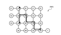
- FIG. 6 is a configuration diagram showing an optical transmission system 200G in a state in which the second optical path has been switched to the third optical path (S17 for the second time) in the optical transmission system 200F in FIG.
- the optical path control unit 22 After deleting the second optical path from the optical transmission system 200F, the optical path control unit 22 creates a third optical path for connecting the user site Y and the site X3 along a route (nodes D4, C4, C3, B3, B2, A2, A3) branching from the common section to the link A2-A3 (S17 for the second time). Note that in the optical transmission system 200G in FIG. 6, the route of the third optical path opened between the nodes D4-A3 is indicated by a solid line.
- the optical transmission system 200 described above is applied to, for example, the following distribution services.
- - Two-way real-time video distribution service For example, when watching a live performance, a service that allows a large number of far-flung audience members and artists to communicate in high quality through high-quality video and real-time communication.
- - Channel switching distribution service In other words, a video distribution service in which a fixed node of a viewer receives video data by switching between multiple video distribution servers (switching nodes).
- ⁇ Inter-site communication services such as camera video traffic (transmission of real-time video from multiple surveillance cameras in a factory to a surveillance site)
- the optical transmission system 200 may be applied to, for example, the following services.
- - Data center backup services backup to multiple data centers from the same user location, backing up data from one data center to another, etc.
- Remote control services For example, remote surgery can be performed by switching a switching node (a doctor's terminal or a technician's terminal) to a fixed node (a medical terminal in an operating room).
- a switching node multiple devices in a factory in a remote location
- a drone delivery service can be provided in which a switching node (each drone terminal) is remotely operated from a fixed node (a delivery staff terminal).
- - Core network connection service for mobile base stations for example, the following services.
- FIG. 7 is a diagram showing a hardware configuration of the optical path design apparatus 100.
- the optical path design apparatus 100 is configured as a computer 900 having a CPU 901 , a RAM 902 , a ROM 903 , a HDD 904 , a communication I/F 905 , an input/output I/F 906 , and a media I/F 907 .
- the communication I/F 905 is connected to an external communication device 915.
- the input/output I/F 906 is connected to an input/output device 916.
- the media I/F 907 reads and writes data from a recording medium 917.
- the CPU 901 controls each unit by executing a program (optical path design program) read into the RAM 902.
- This program also called an application, or an app for short
- the optical path design apparatus 100 of the present invention is an optical path design apparatus 100 that sets an optical path connecting one fixed node serving as a fixed end point and a plurality of switching nodes serving as end points switched with a time difference, a route calculation unit that calculates routes of optical paths including a route that aggregates common routes of a plurality of optical paths for each switching node that connects a fixed node and each switching node;
- the optical path control unit 22 reserves communication resources to be used by an optical path having a specified usage period and usage wavelength on the route of the optical path calculated by the route calculation unit 21, and opens an optical path using the reserved usage wavelength during the reserved usage period.
- the optical path design device 100 reserves the optical path of the route that aggregates the common routes with a limited usage period. Therefore, when one-to-multipoint communication is performed while switching in a time series, the optical path design device 100 can improve the utilization efficiency of the optical path by reducing the amount of resources occupied by the optical path, and realize optical communication at low cost. In other words, for multiple optical paths connecting the same fixed nodes, the amount of reserved resources can be reduced by providing a common route, compared to setting up multiple optical paths between the end points without a common route. This reduction in the amount of reserved resources not only allows telecommunications carriers and service providers to benefit from cost reductions, but also provides them with spare communication resources, allowing them to respond to unexpected demand for communication resources due to the effects of disasters, etc.
- the optical path design device 100 of the present invention is characterized in that the route calculation unit 21 calculates the route of the optical path by solving the minimum spanning tree problem that connects the fixed node and each switching node.
- the optical path design device 100 can set the route of the optical path to bypass high-cost links such as narrowband links, thereby reducing the cost of opening an optical path.
- the optical path design device 100 of the present invention is characterized in that when another reservation occurs that overlaps with the usage period and wavelength of an already reserved route, the optical path control unit 22 rejects the other reservation.
- the optical path design device 100 can prevent overlapping reservations, allowing the optical path to be used when necessary without having to keep the optical path open all the time.
- the optical path design device 100 of the present invention is characterized in that, when the usage period of a specific switching node has elapsed and the usage period of another switching node has begun, the optical path control unit 22 deletes the first optical path opened to connect to the specific switching node, and then opens a new second optical path to connect to the other switching node.
- the optical path design device 100 can increase the efficiency of communication resource usage by appropriately generating and deleting optical paths with limited usage periods.
Landscapes
- Engineering & Computer Science (AREA)
- Computer Networks & Wireless Communication (AREA)
- Signal Processing (AREA)
- Data Exchanges In Wide-Area Networks (AREA)
Priority Applications (2)
| Application Number | Priority Date | Filing Date | Title |
|---|---|---|---|
| PCT/JP2023/018611 WO2024236810A1 (ja) | 2023-05-18 | 2023-05-18 | 光パス設計装置、光パス設計方法、および、光パス設計プログラム |
| JP2025520365A JPWO2024236810A1 (https=) | 2023-05-18 | 2023-05-18 |
Applications Claiming Priority (1)
| Application Number | Priority Date | Filing Date | Title |
|---|---|---|---|
| PCT/JP2023/018611 WO2024236810A1 (ja) | 2023-05-18 | 2023-05-18 | 光パス設計装置、光パス設計方法、および、光パス設計プログラム |
Publications (1)
| Publication Number | Publication Date |
|---|---|
| WO2024236810A1 true WO2024236810A1 (ja) | 2024-11-21 |
Family
ID=93519578
Family Applications (1)
| Application Number | Title | Priority Date | Filing Date |
|---|---|---|---|
| PCT/JP2023/018611 Ceased WO2024236810A1 (ja) | 2023-05-18 | 2023-05-18 | 光パス設計装置、光パス設計方法、および、光パス設計プログラム |
Country Status (2)
| Country | Link |
|---|---|
| JP (1) | JPWO2024236810A1 (https=) |
| WO (1) | WO2024236810A1 (https=) |
Citations (2)
| Publication number | Priority date | Publication date | Assignee | Title |
|---|---|---|---|---|
| JP2011188046A (ja) * | 2010-03-05 | 2011-09-22 | Hitachi Ltd | パケット通信システム及びパケット通信装置制御方法 |
| WO2022102134A1 (ja) * | 2020-11-16 | 2022-05-19 | 日本電信電話株式会社 | 通信経路探索装置、通信経路探索方法、及びプログラム |
-
2023
- 2023-05-18 JP JP2025520365A patent/JPWO2024236810A1/ja active Pending
- 2023-05-18 WO PCT/JP2023/018611 patent/WO2024236810A1/ja not_active Ceased
Patent Citations (2)
| Publication number | Priority date | Publication date | Assignee | Title |
|---|---|---|---|---|
| JP2011188046A (ja) * | 2010-03-05 | 2011-09-22 | Hitachi Ltd | パケット通信システム及びパケット通信装置制御方法 |
| WO2022102134A1 (ja) * | 2020-11-16 | 2022-05-19 | 日本電信電話株式会社 | 通信経路探索装置、通信経路探索方法、及びプログラム |
Also Published As
| Publication number | Publication date |
|---|---|
| JPWO2024236810A1 (https=) | 2024-11-21 |
Similar Documents
| Publication | Publication Date | Title |
|---|---|---|
| Yao et al. | On fast and coordinated data backup in geo-distributed optical inter-datacenter networks | |
| CN115277578B (zh) | 一种业务编排方法、装置及存储介质 | |
| US20140098673A1 (en) | Software Defined Network Virtualization Utilizing Service Specific Topology Abstraction and Interface | |
| CN103780471B (zh) | 一种应用于软件定义网络的多控制器管理网络设备的方法 | |
| CN101079729B (zh) | 对网络资源进行预留的方法 | |
| US11245618B2 (en) | Multicast traceroute facility with batch query processing for multiple flows and reservation of resources for requested link metrics | |
| KR101417195B1 (ko) | 다계층 네트워크에서의 계층간 경로 설정 방법 및 시스템 | |
| JP2005312048A (ja) | ネットワークトラフィックを管理する方法、システム及び論理装置 | |
| CN102907051A (zh) | 标记交换路径建立方法、数据转发方法及设备 | |
| CN100375456C (zh) | 智能光网络中实现光组播的方法 | |
| DeFanti et al. | Optical switching middleware for the OptIPuter | |
| CN110650171B (zh) | 一种视联网业务调度系统及方法 | |
| Tomkos et al. | Application aware multilayer control and optimization of elastic WDM switched optical networks | |
| Gifre et al. | Experimental assessment of ABNO-driven multicast connectivity in flexgrid networks | |
| WO2024236810A1 (ja) | 光パス設計装置、光パス設計方法、および、光パス設計プログラム | |
| CN114513447B (zh) | Sd-wan业务发放系统、方法、装置和网络设备 | |
| JP2012074825A (ja) | QoS保障型ネットワークシステム、集中制御装置、及び集中制御装置の制御方法 | |
| JP3919746B2 (ja) | Wdmネットワークシステム及びこれに用いるwdmノード | |
| CN109005473B (zh) | 一种协同选择路径的方法、装置及系统 | |
| US20240056704A1 (en) | Cascaded optical switch | |
| KR100333679B1 (ko) | 멀티캐스트 통신 서비스 제공 시스템 및 멀티캐스트 서비스제어방법 | |
| JP4809820B2 (ja) | 配信予約方法及び予約管理装置及び配信予約プログラム | |
| JP4820832B2 (ja) | 仮想プライベートネットワーク管理システム | |
| WO2021249478A1 (zh) | 资源部署方法、设备、管控系统及计算机存储介质 | |
| JP6892205B2 (ja) | 多地点間通信システム及び方法並びにプログラム |
Legal Events
| Date | Code | Title | Description |
|---|---|---|---|
| 121 | Ep: the epo has been informed by wipo that ep was designated in this application |
Ref document number: 23937546 Country of ref document: EP Kind code of ref document: A1 |
|
| ENP | Entry into the national phase |
Ref document number: 2025520365 Country of ref document: JP Kind code of ref document: A |
|
| WWE | Wipo information: entry into national phase |
Ref document number: 2025520365 Country of ref document: JP |
|
| NENP | Non-entry into the national phase |
Ref country code: DE |