WO2024236807A1 - リチウム2次電池用正極及びリチウム2次電池 - Google Patents
リチウム2次電池用正極及びリチウム2次電池 Download PDFInfo
- Publication number
- WO2024236807A1 WO2024236807A1 PCT/JP2023/018604 JP2023018604W WO2024236807A1 WO 2024236807 A1 WO2024236807 A1 WO 2024236807A1 JP 2023018604 W JP2023018604 W JP 2023018604W WO 2024236807 A1 WO2024236807 A1 WO 2024236807A1
- Authority
- WO
- WIPO (PCT)
- Prior art keywords
- positive electrode
- active material
- electrode active
- less
- material particles
- Prior art date
- Legal status (The legal status is an assumption and is not a legal conclusion. Google has not performed a legal analysis and makes no representation as to the accuracy of the status listed.)
- Ceased
Links
Images

Classifications
-
- H—ELECTRICITY
- H01—ELECTRIC ELEMENTS
- H01M—PROCESSES OR MEANS, e.g. BATTERIES, FOR THE DIRECT CONVERSION OF CHEMICAL ENERGY INTO ELECTRICAL ENERGY
- H01M4/00—Electrodes
- H01M4/02—Electrodes composed of, or comprising, active material
- H01M4/62—Selection of inactive substances as ingredients for active masses, e.g. binders, fillers
- H01M4/621—Binders
- H01M4/622—Binders being polymers
- H01M4/623—Binders being polymers fluorinated polymers
-
- H—ELECTRICITY
- H01—ELECTRIC ELEMENTS
- H01M—PROCESSES OR MEANS, e.g. BATTERIES, FOR THE DIRECT CONVERSION OF CHEMICAL ENERGY INTO ELECTRICAL ENERGY
- H01M10/00—Secondary cells; Manufacture thereof
- H01M10/05—Accumulators with non-aqueous electrolyte
- H01M10/052—Li-accumulators
-
- H—ELECTRICITY
- H01—ELECTRIC ELEMENTS
- H01M—PROCESSES OR MEANS, e.g. BATTERIES, FOR THE DIRECT CONVERSION OF CHEMICAL ENERGY INTO ELECTRICAL ENERGY
- H01M10/00—Secondary cells; Manufacture thereof
- H01M10/05—Accumulators with non-aqueous electrolyte
- H01M10/052—Li-accumulators
- H01M10/0525—Rocking-chair batteries, i.e. batteries with lithium insertion or intercalation in both electrodes; Lithium-ion batteries
-
- H—ELECTRICITY
- H01—ELECTRIC ELEMENTS
- H01M—PROCESSES OR MEANS, e.g. BATTERIES, FOR THE DIRECT CONVERSION OF CHEMICAL ENERGY INTO ELECTRICAL ENERGY
- H01M4/00—Electrodes
- H01M4/02—Electrodes composed of, or comprising, active material
- H01M4/13—Electrodes for accumulators with non-aqueous electrolyte, e.g. for lithium-accumulators; Processes of manufacture thereof
- H01M4/131—Electrodes based on mixed oxides or hydroxides, or on mixtures of oxides or hydroxides, e.g. LiCoOx
-
- H—ELECTRICITY
- H01—ELECTRIC ELEMENTS
- H01M—PROCESSES OR MEANS, e.g. BATTERIES, FOR THE DIRECT CONVERSION OF CHEMICAL ENERGY INTO ELECTRICAL ENERGY
- H01M4/00—Electrodes
- H01M4/02—Electrodes composed of, or comprising, active material
- H01M4/36—Selection of substances as active materials, active masses, active liquids
- H01M4/362—Composites
- H01M4/364—Composites as mixtures
-
- H—ELECTRICITY
- H01—ELECTRIC ELEMENTS
- H01M—PROCESSES OR MEANS, e.g. BATTERIES, FOR THE DIRECT CONVERSION OF CHEMICAL ENERGY INTO ELECTRICAL ENERGY
- H01M4/00—Electrodes
- H01M4/02—Electrodes composed of, or comprising, active material
- H01M4/64—Carriers or collectors
- H01M4/66—Selection of materials
- H01M4/661—Metal or alloys, e.g. alloy coatings
-
- H—ELECTRICITY
- H01—ELECTRIC ELEMENTS
- H01M—PROCESSES OR MEANS, e.g. BATTERIES, FOR THE DIRECT CONVERSION OF CHEMICAL ENERGY INTO ELECTRICAL ENERGY
- H01M4/00—Electrodes
- H01M4/02—Electrodes composed of, or comprising, active material
- H01M4/64—Carriers or collectors
- H01M4/66—Selection of materials
- H01M4/665—Composites
- H01M4/667—Composites in the form of layers, e.g. coatings
-
- H—ELECTRICITY
- H01—ELECTRIC ELEMENTS
- H01M—PROCESSES OR MEANS, e.g. BATTERIES, FOR THE DIRECT CONVERSION OF CHEMICAL ENERGY INTO ELECTRICAL ENERGY
- H01M4/00—Electrodes
- H01M4/02—Electrodes composed of, or comprising, active material
- H01M4/64—Carriers or collectors
- H01M4/66—Selection of materials
- H01M4/668—Composites of electroconductive material and synthetic resins
-
- H—ELECTRICITY
- H01—ELECTRIC ELEMENTS
- H01M—PROCESSES OR MEANS, e.g. BATTERIES, FOR THE DIRECT CONVERSION OF CHEMICAL ENERGY INTO ELECTRICAL ENERGY
- H01M4/00—Electrodes
- H01M4/02—Electrodes composed of, or comprising, active material
- H01M2004/021—Physical characteristics, e.g. porosity, surface area
-
- H—ELECTRICITY
- H01—ELECTRIC ELEMENTS
- H01M—PROCESSES OR MEANS, e.g. BATTERIES, FOR THE DIRECT CONVERSION OF CHEMICAL ENERGY INTO ELECTRICAL ENERGY
- H01M4/00—Electrodes
- H01M4/02—Electrodes composed of, or comprising, active material
- H01M2004/026—Electrodes composed of, or comprising, active material characterised by the polarity
- H01M2004/028—Positive electrodes
-
- Y—GENERAL TAGGING OF NEW TECHNOLOGICAL DEVELOPMENTS; GENERAL TAGGING OF CROSS-SECTIONAL TECHNOLOGIES SPANNING OVER SEVERAL SECTIONS OF THE IPC; TECHNICAL SUBJECTS COVERED BY FORMER USPC CROSS-REFERENCE ART COLLECTIONS [XRACs] AND DIGESTS
- Y02—TECHNOLOGIES OR APPLICATIONS FOR MITIGATION OR ADAPTATION AGAINST CLIMATE CHANGE
- Y02E—REDUCTION OF GREENHOUSE GAS [GHG] EMISSIONS, RELATED TO ENERGY GENERATION, TRANSMISSION OR DISTRIBUTION
- Y02E60/00—Enabling technologies; Technologies with a potential or indirect contribution to GHG emissions mitigation
- Y02E60/10—Energy storage using batteries
Definitions
- the present invention relates to a positive electrode for a lithium secondary battery and a lithium secondary battery.
- lithium secondary batteries which charge and discharge by the movement of lithium ions between the positive and negative electrodes, are known to exhibit high voltage and high energy density.
- a typical lithium secondary battery is the lithium-ion secondary battery (LIB), which has active materials capable of retaining lithium elements in the positive and negative electrodes and charges and discharges by the exchange of lithium ions between the positive and negative active materials.
- LIB lithium-ion secondary battery
- Patent Document 1 discloses that the safety of battery cells can be improved by using a current collector film in which metal layers are formed on both sides of a resin film.
- the present invention was made in consideration of the above problems, and aims to provide a positive electrode that has high safety and good rate characteristics in a lithium secondary battery.
- a positive electrode for a lithium secondary battery includes a collector film having a resin layer and metal layers provided on both sides of the resin layer, and a positive electrode composite layer formed on the collector film, the positive electrode composite layer including first positive electrode active material particles having a median diameter D50 of 10 ⁇ m or more and 25 ⁇ m or less, second positive electrode active material particles, and two or more types of binders, and the second positive electrode active material particles are mixed with the first positive electrode active material particles.
- the median diameter D50 ratio of the particles ([median diameter D50 of the second positive electrode active material particles]/[median diameter D50 of the first positive electrode active material particles]) is 0.75 or less, and the mass ratio of the first positive electrode active material particles to the second positive electrode active material particles in the positive electrode ([content of the first positive electrode active material particles in the positive electrode]/[content of the second positive electrode active material particles in the positive electrode]) is 1.5 or more and 9.0 or less.
- the positive electrode includes a collector film having a resin layer and metal layers provided on both sides of the resin layer, thereby providing a high level of safety.
- the positive electrode mixture layer includes first positive electrode active material particles having a median diameter D50 of 10 ⁇ m or more and 25 ⁇ m or less, second positive electrode active material particles, and two or more types of binders, the median diameter D50 ratio of the second positive electrode active material particles to the first positive electrode active material particles ([median diameter D50 of the second positive electrode active material particles]/[median diameter D50 of the first positive electrode active material particles]) is 0.75 or less, and the mass ratio of the first positive electrode active material particles to the second positive electrode active material particles in the positive electrode ([content of the first positive electrode active material particles in the positive electrode]/[content of the second positive electrode active material particles in the positive electrode]) is 1.5 or more and 9.0 or less, thereby having good rate characteristics. Therefore, it is presumed that the above-mentioned components achieve both high safety and good rate
- the metal layer is preferably formed from aluminum.
- the lithium secondary battery tends to be even safer.
- the mass ratio in the positive electrode of the first positive electrode active material particles to the second positive electrode active material particles is 2.0 or more and 9.0 or less. According to such an embodiment, the lithium secondary battery tends to have even more excellent rate characteristics.
- the median diameter D50 ratio of the second positive electrode active material particles to the first positive electrode active material particles is preferably 0.1 or more and 0.5 or less. According to such an embodiment, the lithium secondary battery tends to have even more excellent rate characteristics.
- the median diameter D50 of the first positive electrode active material particles is preferably 10 ⁇ m or more and 20 ⁇ m or less. According to such an embodiment, the lithium secondary battery tends to have even better rate characteristics.
- the binder preferably includes a first binder having vinylidene fluoride as a repeating unit and a second binder having tetrafluoroethylene as a repeating unit. According to such an embodiment, the lithium secondary battery tends to have even more excellent rate characteristics.
- the mass ratio of the second binder to the first binder in the positive electrode ([content of the second binder in the positive electrode]/[content of the first binder in the positive electrode]) is 1.0 or more and 10.0 or less. According to such an embodiment, the lithium secondary battery tends to have even more excellent rate characteristics.
- the positive electrode for a lithium secondary battery preferably comprises any one of the positive electrodes described above. This aspect tends to result in even better safety and rate characteristics.
- the present invention makes it possible to provide a positive electrode for a lithium secondary battery that combines high safety with good rate characteristics.
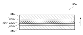
- FIG. 2 is a diagram showing an example of a cross-sectional structure of a positive electrode according to one embodiment of the present invention.
- FIG. 4 is a diagram showing another example of the cross-sectional structure of a positive electrode according to an embodiment of the present invention.
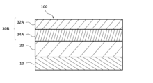
- 1 is a schematic cross-sectional view of a lithium secondary battery according to an embodiment of the present invention.
- the present embodiment an embodiment of the present invention (hereinafter referred to as "the present embodiment") will be described in detail with reference to the drawings as necessary, but the present invention is not limited to this, and various modifications are possible without departing from the gist of the invention.
- the same elements are given the same reference numerals, and duplicated explanations will be omitted.
- positional relationships such as up, down, left, and right will be based on the positional relationships shown in the drawings.
- the dimensional ratios of the drawings are not limited to those shown.
- the positive electrode 30 of the present embodiment includes a current collector film 32A including a resin layer 320A and metal layers 322A provided on both sides of the resin layer 320A, and a positive electrode mixture layer 34A formed on the current collector film 32A.
- the positive electrode mixture layer 34A includes positive electrode active material particles L (first positive electrode active material particles) having a median diameter D50 of 10 ⁇ m or more and 25 ⁇ m or less, and positive electrode active material particles S (second positive electrode active material particles).
- a median diameter D50 ratio of the positive electrode active material particles S to the positive electrode active material particles L is 0.75 or less, and a mass ratio in the positive electrode of the positive electrode active material particles L to the positive electrode active material particles S ([content of the positive electrode active material particles L in the positive electrode]/[content of the positive electrode active material particles S in the positive electrode]) is 1.5 or more and 9.0 or less.
- the positive electrode composite layer 34A may be formed on both sides of the current collector film 32A to form the positive electrode 30A, and as shown in FIG. 2, the positive electrode composite layer 34A may be formed on at least one side of the current collector film 32A to form the positive electrode 30B.
- the positive electrode 30 includes both the positive electrode 30A and the positive electrode 30B.
- the resin layer 320A melts in the event of abnormal heat generation due to overcharging or high temperature conditions, and can function to cut off the short-circuit current inside the battery. This tends to suppress a sudden rise in temperature inside the battery, suppress battery ignition, and contribute to high safety.
- the current collector film 32A contains a resin that has a lower density than metal, and has a lower weight per volume than a current collector that has only a metal layer, so lithium secondary batteries that use the current collector film 32A tend to have excellent energy density per weight.
- the positive electrode When manufacturing lithium secondary batteries, the positive electrode is often pressed to reduce its volume in order to make it smaller and more dense. Comparing a case where the positive electrode has only a metal layer as a current collector with a case where the positive electrode includes a current collector film having a resin layer and metal layers provided on both sides of the resin layer, when the positive electrode is pressed, the current collector film tends to stretch more in the direction perpendicular to the pressing direction, i.e., tends to have greater strain, than a current collector having only a metal layer. This is presumably because resins tend to have a smaller Young's modulus than metals, and so a current collector film having a resin layer and a metal layer has a smaller Young's modulus than a current collector having only a metal layer. However, the cause is not limited to this.
- the layer containing the positive electrode active material formed on the current collector film also tries to stretch accordingly; however, because the Young's modulus of the layer containing the positive electrode active material is relatively large, it is unable to keep up with this stretch, and cracks and the like occur in the layer containing the positive electrode active material, resulting in deterioration of the characteristics of the positive electrode and a tendency for the cycle characteristics of the lithium secondary battery to deteriorate.
- the layer containing the positive electrode active material is unable to keep up with the stretch of the current collector film, which comprises a resin layer and metal layers provided on both sides of the resin layer, and as a result, cracks occur in the layer containing the positive electrode active material, causing the electron conduction path to be cut in the layer containing the positive electrode active material.
- the cause is not limited to this.
- a positive electrode mixture layer 34A containing a positive electrode active material which contains positive electrode active material particles L having a median diameter D50 of 10 ⁇ m or more and 25 ⁇ m or less, and positive electrode active material particles S, in which the median diameter D50 ratio of the positive electrode active material particles S to the positive electrode active material particles L is 0.75 or less, and the mass ratio in the positive electrode of the positive electrode active material particles L to the positive electrode active material particles S ([content of the positive electrode active material particles L in the positive electrode]/[content of the positive electrode active material particles S in the positive electrode]) is 1.5 or more and 9.0 or less, a high energy density per volume, good cycle characteristics, and good rate characteristics can be achieved simultaneously, even when the current collector film 32A of this embodiment is used.
- the reason for this is presumed to be, but is not limited to, the following.
- the volume can be made smaller with the same pressing pressure when using a positive electrode composite layer 34A containing two types of positive electrode active material particles, that is, positive electrode active material particles with a moderately large D50 and positive electrode active material particles with a small D50, and in which the two types of positive electrode active material particles exist in an appropriate mass ratio. This is thought to be because, when the positive electrode is pressed, the positive electrode active material particles with a small D50 enter the gaps between the positive electrode active material particles with a moderately large D50.
- the positive electrode when using a positive electrode composite layer 34A containing two types of positive electrode active material particles, that is, positive electrode active material particles with a moderately large D50 and positive electrode active material particles with a small D50, and in which the two types of positive electrode active material particles exist in an appropriate mass ratio, the positive electrode can be made smaller and more dense with a low pressing pressure, and as a result, the energy density per volume of the lithium secondary battery tends to be improved.
- the elongation of the current collector film 32A which includes the resin layer 320A and the metal layers 322A provided on both sides of the resin layer 320A, is also small, so that the positive electrode composite layer 34A can follow the elongation of the current collector film 32A, and the characteristics of the positive electrode are not deteriorated. As a result, the cycle characteristics and rate characteristics of the lithium secondary battery tend to improve.
- the Young's modulus of the positive electrode composite layer 34A becomes smaller, and when the positive electrode 30 is pressed, the positive electrode composite layer 34A is more likely to follow the expansion of the current collector film 32A, so that even if the positive electrode 30 is pressed with a greater pressure, the characteristics of the positive electrode tend not to deteriorate. Therefore, it becomes possible to press the positive electrode 30 with a greater pressure, and the energy density per volume tends to be greater.
- the factors behind this are not limited to those mentioned above.
- a lithium secondary battery including the positive electrode 30 of this embodiment can achieve high safety, high energy density per weight, high energy density per volume, good cycle characteristics, and good rate characteristics.
- the factors are not limited to those mentioned above.
- the average thickness of the positive electrode 30 after pressing is not particularly limited, but is, for example, 50 ⁇ m or more and 500 ⁇ m or less, 100 ⁇ m or more and 400 ⁇ m or less, or 150 ⁇ m or more and 350 ⁇ m or less.
- the density of the positive electrode 30 after pressing is preferably 2.5 g/cc or more and 7.5 g/cc or less, 3.0 g/cc or more and 6.5 g/cc or less, or 3.3 g/cc or more and 5.0 g/cc or less.
- the components contained in the positive electrode 30 are described in detail below.
- the current collector film 32A includes a resin layer 320A and metal layers 322A provided on both sides of the resin layer 320A.
- the metal layers 322A are formed on both sides of the resin layer 320A by vapor deposition, sputtering, electrolytic plating, or by bonding with an adhesive. Use of the current collector film 32A tends to provide excellent safety and energy density per weight.
- the resin layer 320A is an insulator, and prevents the metal layers 322A provided on both sides of the resin layer 320A from being electrically connected to each other.
- the resin constituting the resin layer 320A is not particularly limited, but may be, for example, a sheet-shaped (film-shaped) or fibrous resin.
- the resin is not particularly limited, but may be, for example, a polyolefin resin such as polyethylene terephthalate (PET), polyethylene, or polypropylene, or a thermoplastic resin such as polystyrene, polyvinyl chloride, or polyamide.
- PET polyethylene terephthalate
- the resin in the resin layer 320A may be used alone or in combination of two or more types.
- the above-mentioned resins may be mixed to form one resin layer 320A, or the above-mentioned resins may be used alone to form a layer, and then multiple layers may be combined to form one resin layer 320A.
- the resin layer 320A may contain other additives as appropriate depending on the desired physical properties.
- additives include, but are not limited to, colorants, flame retardants, surfactants, etc.
- the resin content in resin layer 320A is not particularly limited, but may be, for example, 60% by mass or more and 100% by mass or less, 80% by mass or more and 100% by mass or less, 90% by mass or more and 100% by mass or less, or 95% by mass or more and 100% by mass or less, relative to the total amount of resin layer 320A.
- the thickness of the resin layer 320A before pressing is not particularly limited, but may be, for example, 2.0 ⁇ m or more and 12.0 ⁇ m or less, or 3.0 ⁇ m or more and 10.0 ⁇ m or less.
- the metal layer 322A is in physical and/or electrical contact with the positive electrode composite layer 34A described below, and functions to give and receive electrons to and from the positive electrode composite layer 34A.
- the metal layer 322A is made of a conductor such as a metal that does not react with lithium in a battery.
- the metal constituting the metal layer 322A is not particularly limited, but is at least one selected from the group consisting of aluminum, titanium, stainless steel, nickel, and alloys thereof. Among these, aluminum or an aluminum alloy is preferable, and aluminum is particularly preferable.
- the metal may be used alone or in combination of two or more types.
- each metal layer 322A before pressing is not particularly limited, but may be, for example, 0.2 ⁇ m or more and 5.0 ⁇ m or less, 0.3 ⁇ m or more and 4.0 ⁇ m or less, or 0.5 ⁇ m or more and 3.0 ⁇ m or less.
- the positive electrode mixture layer 34A of the present embodiment contains positive electrode active material particles L and positive electrode active material particles S, which will be described later, and a binder, and may further contain a conductive assistant, a sacrificial positive electrode agent, and other components.
- Positive electrode active material particles are particles formed by a positive electrode active material.
- the positive electrode active material is a material that causes an electrode reaction, i.e., an oxidation reaction and a reduction reaction, at the positive electrode.
- the positive electrode active material of this embodiment includes a host material of a lithium element (typically, a lithium ion).
- Such positive electrode active materials include, but are not limited to, metal oxides and metal phosphates.
- the metal oxides include, but are not limited to, cobalt oxide-based compounds, manganese oxide-based compounds, and nickel oxide-based compounds.
- the metal phosphates include, but are not limited to, iron phosphate-based compounds and cobalt phosphate-based compounds.
- Typical positive electrode active materials include LiCoO2 , LizNixCoyM1 -x-yO2 + ⁇ (where 0.5 ⁇ x ⁇ 1.0, 0 ⁇ y ⁇ 0.35, 0.9 ⁇ z ⁇ 1.3, -0.2 ⁇ 0.15, and M is at least one element selected from Mn, Al, V, Mg, Mo, Nb, Ti, Zr, Fe, Cu, Cr, Zn, F, and B.
- the above positive electrode active materials may be used alone or in combination of two or more.
- the positive electrode active material particles of this embodiment include positive electrode active material particles L (hereinafter also referred to as “particles L”) having a median diameter D50 (hereinafter also referred to as "D50") of 10 ⁇ m or more and 25 ⁇ m or less, and positive electrode active material particles S (hereinafter also referred to as “particles S”), the D50 ratio of particles S to particles L is 0.75 or less, and the mass ratio of particles L to particles S in the positive electrode ([content of particles L in the positive electrode]/[content of particles S in the positive electrode]) is 1.5 or more and 9.0 or less.
- P50 median diameter
- S positive electrode active material particles S
- the “median diameter” is the particle diameter corresponding to a cumulative degree of 50% in the particle size distribution measured by a laser diffraction/scattering method, and is determined so that the number of particles larger than the median diameter and the number of particles smaller than the median diameter are the same.
- the particle size distribution can be measured by a known method. More specifically, but not limited to, it can be measured, for example, by a laser diffraction particle size distribution measuring device.
- the D50 of the particles L is 10.0 ⁇ m or more and 25.0 ⁇ m or less, preferably 11.0 ⁇ m or more and 24.0 ⁇ m or less, 12.0 ⁇ m or more and 23.0 ⁇ m or less, or 13.0 ⁇ m or more and 22.0 ⁇ m or less. Also, preferably 10.0 ⁇ m or more and 20.0 ⁇ m or less.
- the energy density per volume, cycle characteristics, and rate characteristics tend to be further improved.
- the D50 of the particles S is preferably 0.5 ⁇ m or more and 19.0 ⁇ m or less, 0.5 ⁇ m or more and 15.0 ⁇ m or less, 0.5 ⁇ m or more and 10.0 ⁇ m or less, 1.0 ⁇ m or more and 9.0 ⁇ m or less, 2.0 ⁇ m or more and 8.0 ⁇ m or less, 2.5 ⁇ m or more and 7.5 ⁇ m or less, 3.0 ⁇ m or more and 7.0 ⁇ m or less, and 3.5 ⁇ m or more and 6.5 ⁇ m or less. Also, it is preferably 0.5 ⁇ m or more and less than 10.0 ⁇ m. When the D50 of the particles S is within the above numerical range, the energy density per volume, the cycle characteristics, and the rate characteristics tend to be further improved.
- the D50 ratio of particle S to particle L ([median diameter D50 of particle S]/[median diameter D50 of particle L]) is 0.75 or less, and preferably 0.05 to 0.75, 0.10 to 0.60, 0.10 to 0.50, 0.15 to 0.45, or 0.20 to 0.40.
- the D50 ratio of particle S to particle L is within the above numerical range, the energy density per volume, cycle characteristics, and rate characteristics tend to be further improved.
- the particle L preferably has a particle diameter D90 (hereinafter also referred to as "D90") corresponding to a cumulative degree of 90% in the particle size distribution measured by a laser diffraction/scattering method of 25.0 ⁇ m or less, 13.0 ⁇ m or more and 25.0 ⁇ m or less, 13.5 ⁇ m or more and 24.5 ⁇ m or less, or 14.0 ⁇ m or more and 24.0 ⁇ m or less.
- D90 particle diameter
- the particle L preferably has a particle diameter D90 (hereinafter also referred to as "D90") corresponding to a cumulative degree of 90% in the particle size distribution measured by a laser diffraction/scattering method of 25.0 ⁇ m or less, 13.0 ⁇ m or more and 25.0 ⁇ m or less, 13.5 ⁇ m or more and 24.5 ⁇ m or less, or 14.0 ⁇ m or more and 24.0 ⁇ m or less.
- the D90 of the particles S is preferably 19.0 ⁇ m or less, 15.0 ⁇ m or less, 10.0 ⁇ m or less, 1.5 ⁇ m or more and 9.0 ⁇ m or less, 2.0 ⁇ m or more and 8.0 ⁇ m or less, 2.5 ⁇ m or more and 7.5 ⁇ m or less, 3.0 ⁇ m or more and 6.5 ⁇ m or less, or 3.5 ⁇ m or more and 6.0 ⁇ m or less.
- the energy density per volume, cycle characteristics, and rate characteristics tend to be further improved.
- Particles L are preferably such that 75% or more of the particles exist within a range of ⁇ 0.5 ⁇ m of D50, 80% or more of the particles exist, 85% or more of the particles exist, 90% or more of the particles exist, or 95% or more of the particles exist within a range of ⁇ 0.5 ⁇ m of D50.
- the particles S are preferably such that 75% or more of the particles exist, 80% or more of the particles exist, 85% or more of the particles exist, 90% or more of the particles exist, or 95% or more of the particles exist within a range of ⁇ 0.5 ⁇ m of D50.
- a maximum value may exist in a region where the particle size is 10.0 ⁇ m or more, and a maximum value may exist in a region where the particle size is 0.75 times the particle size at the maximum value or less, in which case, either of the two maximum values may be the maximum value in the particle size distribution, and the other may be the second largest peak.
- a maximum value may exist in a region where the particle size is 10.0 ⁇ m or more, and a maximum value may exist in a region where the particle size is 7.5 ⁇ m or less, in which case, either the maximum value in the region where the particle size is 10.0 ⁇ m or more or the maximum value in the region where the particle size is 7.5 ⁇ m or less may be the maximum value in the particle size distribution, and the other may be the second largest peak.
- the maximum value in the region where the particle size is 12.0 ⁇ m or more there may be a maximum value in the region where the particle size is 12.0 ⁇ m or more, and a maximum value in the region where the particle size is 5.0 ⁇ m or less, in which case either the maximum value in the region where the particle size is 12.0 ⁇ m or more or the maximum value in the region where the particle size is 5.0 ⁇ m or less may be the maximum value in the particle size distribution, and the other may be the second largest peak.
- the content of particles L is preferably 30.0 mass% or more and 90.0 mass% or less, 40.0 mass% or more and 85.0 mass% or less, 50.0 mass% or more and 80.0 mass% or less, 55.0 mass% or more and 77.5 mass% or less, or 60.0 mass% or more and 75.0 mass% or less, relative to the total amount of the positive electrode composite layer 34A.
- the content of particle S is preferably 5.0 mass% or more and 50.0 mass% or less, 7.5 mass% or more and 45.0 mass% or less, 10.0 mass% or more and 42.5 mass% or less, 11.0 mass% or more and 40.0 mass% or less, or 12.0 mass% or more and 37.5 mass% or less, relative to the total amount of the positive electrode composite layer 34A.
- the content of the positive electrode active material particles is preferably 60.0% by mass or more and 99.0% by mass or less, 70.0% by mass or more and 98.5% by mass or less, 80.0% by mass or more and 98.0% by mass or less, or 85.0% by mass or more and 97.5% by mass or less, relative to the total amount of the positive electrode composite layer 34A.
- the mass ratio of particles L to particles S in the positive electrode 30 ([content of particles L in positive electrode 30]/[content of particles S in positive electrode 30]) is 1.5 or more and 9.0 or less, preferably 2.0 or more and 9.0 or less, 2.1 or more and 8.0 or less, or 2.2 or more and 7.0 or less.
- the mass ratio of particles L to particles S is within the above numerical range, the energy density per volume, cycle characteristics, and rate characteristics tend to be further improved.
- the positive electrode mixture layer 34A of this embodiment contains two or more binders. By containing a binder, the positive electrode mixture layer 34A is improved in elongation when a force is applied thereto, that is, the Young's modulus is reduced.
- the positive electrode 30 including the current collector film 32A and the positive electrode mixture layer 34A formed on the current collector film 32A is pressed, the positive electrode mixture layer 34A tends to easily follow the elongation of the current collector film 32A, and even if the positive electrode 30 is pressed with a larger pressure, the characteristics of the positive electrode tend not to deteriorate. Therefore, it becomes possible to press the positive electrode 30 with a larger pressure, and the energy density per volume tends to be larger.
- the binder is not particularly limited, but examples include binder 1 (first binder) having vinylidene fluoride as a repeating unit, binder 2 (second binder) having tetrafluoroethylene as a repeating unit, styrene butadiene rubber, acrylic resin, polyimide resin, etc. Among these, binder 1 and binder 2 are preferred, and it is more preferred to use binder 1 and binder 2 in combination.
- the binder 1 is not particularly limited, but examples thereof include polyvinylidene fluoride, which is a homopolymer of vinylidene fluoride, and modified polyvinylidene fluoride in which functional groups such as hydroxyl groups, amino groups, carbonyl groups, carboxyl groups, phenyl groups, and methyl groups have been introduced into polyvinylidene fluoride.
- polyvinylidene fluoride which is a homopolymer of vinylidene fluoride
- modified polyvinylidene fluoride in which functional groups such as hydroxyl groups, amino groups, carbonyl groups, carboxyl groups, phenyl groups, and methyl groups have been introduced into polyvinylidene fluoride.
- the positive electrode mixture layer 34A contains the binder 1
- the positive electrode mixture layer 34A tends to be more easily bonded to the current collector film 32A.
- the binder 1 as described above may be used alone or in combination of two or more types.
- Binder 2 is not particularly limited, but examples thereof include polytetrafluoroethylene, which is a homopolymer of tetrafluoroethylene; modified polytetrafluoroethylene in which functional groups such as hydroxyl groups, amino groups, carbonyl groups, carboxyl groups, phenyl groups, and methyl groups have been introduced into polytetrafluoroethylene; block copolymers, random copolymers, or graft copolymers having tetrafluoroethylene and vinylidene fluoride as repeating units; block copolymers, random copolymers, or graft copolymers having tetrafluoroethylene and hexafluoropropene as repeating units; and block copolymers, random copolymers, or graft copolymers having tetrafluoroethylene, vinylidene fluoride, and hexafluoropropene as repeating units.
- the binder 2 in the positive electrode composite layer 34A By including the binder 2 in the positive electrode composite layer 34A, the flexibility of the positive electrode composite layer 34A is improved and the Young's modulus is reduced. Therefore, when the positive electrode 30 including the current collector film 32A and the positive electrode composite layer 34A formed on the current collector film 32A is pressed, the positive electrode composite layer 34A tends to follow the extension of the current collector film 32A, and the energy density per volume tends to be increased.
- the binder 2 as described above may be used alone or in combination of two or more types.
- the content of binder 1 is preferably 0.3 mass% or more and 20.0 mass% or less, 0.5 mass% or more and 15.0 mass% or less, 1.0 mass% or more and 10.0 mass% or less, or 1.5 mass% or more and 7.5 mass% or less, relative to the total amount of the positive electrode mixture layer 34A.
- the positive electrode mixture layer 34A tends to be more easily bonded to the current collector film 32A.
- the content of the binder 2 is preferably 0.3 mass% or more and 20.0 mass% or less, 0.5 mass% or more and 15.0 mass% or less, 1.0 mass% or more and 10.0 mass% or less, or 1.5 mass% or more and 7.5 mass% or less, relative to the total amount of the positive electrode composite layer 34A.
- the binder content is preferably 0.5% by mass or more and 20.0% by mass or less, 1.0% by mass or more and 15.0% by mass or less, 1.5% by mass or more and 10.0% by mass or less, and 2.0% by mass or less and 7.5% by mass or less, relative to the total amount of the positive electrode composite layer 34A.
- the mass ratio of binder 2 to binder 1 in the positive electrode 30 is preferably 1.0 or more and 10.0 or less, 1.0 or more and 5.0 or less, 1.0 or more and 2.5 or less, or 1.0 or more and 2.0 or less.
- the positive electrode mixture layer 34A of this embodiment may contain a conductive assistant.
- the conductive assistant is not particularly limited, but may be, for example, carbon black, single-wall carbon nanotube (SWCNT), multi-wall carbon nanotube (MWCNT), carbon nanofiber (CF), and acetylene black.
- the conductive assistant may be used alone or in combination of two or more kinds.
- the amount of the conductive additive is not particularly limited, but is, for example, 0.5% by mass or more and less than 30.0% by mass relative to the total amount of the positive electrode composite layer 34A.
- the positive electrode mixture layer 34A of this embodiment may contain a sacrificial cathode agent.
- the sacrificial cathode agent of this embodiment is a lithium-containing compound that undergoes an oxidation reaction in the charge/discharge potential range of the positive electrode active material and does not substantially undergo a reduction reaction.
- the positive electrode 30 of this embodiment contains a sacrificial cathode agent, when a lithium secondary battery including the positive electrode 30 is initially charged, the positive electrode active material and the sacrificial cathode agent release lithium ions and undergo an oxidation reaction, releasing electrons to the negative electrode through an external circuit.
- lithium ions derived from the positive electrode active material and the sacrificial cathode agent are precipitated on the surface of the negative electrode.
- the lithium metal precipitated on the surface of the negative electrode is electrolytically dissolved, and electrons move from the negative electrode to the positive electrode 30 through an external circuit.
- the positive electrode active material receives lithium ions and undergoes a reduction reaction, while the sacrificial positive electrode agent does not substantially undergo a reduction reaction within the range of the discharge potential of the positive electrode active material, and it is substantially impossible to return to the state before the oxidation reaction occurs.
- the lithium secondary battery when the lithium secondary battery is discharged after the initial charge, the lithium metal derived from the positive electrode active material is electrolytically dissolved from the negative electrode, while the lithium metal derived from the sacrificial positive electrode agent remains on the negative electrode, and even after the discharge of the battery is completed, some lithium metal remains on the negative electrode.
- the remaining lithium metal serves as a scaffold for further lithium metal to deposit on the negative electrode in the charging step following the initial discharge, so that the lithium metal is more likely to deposit uniformly on the negative electrode in the charging step after the initial discharge. As a result, the lithium secondary battery tends to have better cycle characteristics.
- the sacrificial positive electrode agent examples include, but are not limited to, lithium oxides such as Li 2 O 2 ; lithium nitrides such as Li 3 N; lithium sulfide solid solutions such as Li 2 S-P 2 S 5 , Li 2 S-LiCl, Li 2 S-LiBr, and Li 2 S-LiI; iron-based lithium oxides such as Li 1+x (Ti 1-y Fe y ) 1-x O 2 (0 ⁇ x ⁇ 0.25, 0.4 ⁇ y ⁇ 0.9), Li 2-x Ti 1-z Fe z O 3-y (0 ⁇ x ⁇ 2, 0 ⁇ y ⁇ 1, 0.05 ⁇ z ⁇ 0.95), and Li 5 FeO 4.
- the above-mentioned sacrificial positive electrode agents may be used alone or in combination of two or more.
- the amount of the sacrificial positive electrode agent relative to the total amount of the positive electrode composite layer 34A is not particularly limited, but may be, for example, 1.0% by mass or more and 30.0% by mass or less, 2.0% by mass or more and 20.0% by mass or less, or 3.0% by mass or more and 15.0% by mass or less.
- the total amount of the positive electrode active material particles and the sacrificial positive electrode agent is preferably 60.0 mass% or more and 99.0 mass% or less, 70.0 mass% or more and 98.5 mass% or less, 80.0 mass% or more and 98.0 mass% or less, or 85.0 mass% or more and 97.5 mass% or less, relative to the total amount of the positive electrode composite layer 34A.
- the positive electrode 30 of this embodiment is manufactured, for example, as follows, without being particularly limited.
- the metal layer 322A is formed on both surfaces of the resin layer 320A by deposition, sputtering, electrolytic plating, or bonding with an adhesive to obtain the current collector film 32A of this embodiment.
- the above-mentioned positive electrode active material particles L, the positive electrode active material particles S, two or more binders, and, if necessary, a conductive assistant, a sacrificial positive electrode agent, etc. are mixed to obtain a positive electrode mixture.
- the obtained positive electrode mixture is applied to both sides or one side of the above-mentioned current collector film 32A, and press molded to form a positive electrode mixture layer 34A on both sides or one side of the current collector film 32A to obtain a molded body.
- the obtained molded body is punched out to a predetermined size by punching processing to obtain the positive electrode 30 of this embodiment. Thereafter, the obtained positive electrode 30 may be further pressed as necessary.
- the pressure during press molding is not particularly limited, but for example, the linear pressure is 0.8 to 3.5 t/cm, 1.0 to 3.0 t/cm, 1.2 to 2.8 t/cm, or 1.5 to 2.5 t/cm.
- the lithium secondary battery of this embodiment includes the above-mentioned positive electrode 30.
- the lithium secondary battery has high safety, high energy density per weight, high energy density per volume, good cycle characteristics, and good rate characteristics.
- the type of lithium secondary battery is not particularly limited as long as it is charged and discharged by the oxidation-reduction reaction of lithium and has a positive electrode 30, and examples include lithium ion batteries, lithium metal batteries, anode-free lithium secondary batteries, lithium sulfur batteries, lithium oxygen batteries, and lithium air batteries.
- FIG. 3 is a schematic cross-sectional view of a lithium secondary battery according to one embodiment of the present invention.
- the anode-free battery 100 of this embodiment includes a positive electrode 30B, a negative electrode 10 having no negative electrode active material, a separator 20 disposed between the positive electrode 30B and the negative electrode 10, and an electrolyte not shown in Fig. 3.
- the positive electrode 30B has a positive electrode current collector 32A on the surface opposite to the surface facing the separator 20, and a positive electrode mixture layer 34A on the surface facing the separator 20.
- Each component of the anode-free battery 100 will be described below.
- the anode-free lithium secondary battery of this embodiment (hereinafter also referred to as "anode-free battery” or “AFB”) has a negative electrode 10 made of a negative electrode current collector that does not have a negative electrode active material, and uses the above-mentioned electrolyte.
- the negative electrode active material is a material that causes an electrode reaction, i.e., an oxidation reaction and a reduction reaction, at the negative electrode.
- the negative electrode active material of this embodiment includes lithium metal and a host material of lithium element (lithium ion or lithium metal).
- the host material of lithium element means a material provided to hold lithium ion or lithium metal at the negative electrode. Examples of such holding mechanisms include intercalation, alloying, and metal cluster absorption, and typically, intercalation.
- an anode-free battery before the initial charge of the battery, the negative electrode 10 does not have any negative electrode active material and consists only of a negative electrode current collector. Therefore, after the initial charge, lithium metal is deposited on the negative electrode 10, and charging and discharging are performed by electrolytic dissolution of the deposited lithium metal. Therefore, an anode-free battery has the advantage that the volume occupied by the negative electrode active material and the mass of the negative electrode active material are reduced, and the volume and mass of the entire battery are reduced, so that the energy density is, in principle, high.
- the anode-free battery includes a negative electrode 10 made of a negative electrode current collector that does not have a negative electrode active material.
- the anode has no anode active material
- the anode 10 substantially does not have anode active material means that the content of the anode active material in the anode 10 is 10.0 mass% or less relative to the entire anode 10.
- the content of the anode active material in the anode 10 of the anode-free battery is preferably 5.0 mass% or less, 1.0 mass% or less, 0.1 mass% or less, or 0.0 mass% relative to the entire anode 10.
- the battery when the battery is "before the initial charge” it means the state from when the battery is assembled until the first charge. Also, when the battery is “at the end of discharge” it means the state in which the battery voltage is preferably 1.0 V or more and 3.8 V or less, and more preferably 1.0 V or more and 3.0 V or less.
- the lithium metal content when the battery voltage is 1.0 V or more and 3.5 V or less, the lithium metal content may be 10.0 mass % or less (preferably 5.0 mass % or less, 1.0 mass % or less) relative to the entire negative electrode 10; when the battery voltage is 1.0 V or more and 3.0 V or less, the lithium metal content may be 10.0 mass % or less (preferably 5.0 mass % or less, 1.0 mass % or less) relative to the entire negative electrode 10; or when the battery voltage is 1.0 V or more and 2.5 V or less, the lithium metal content may be 10.0 mass % or less (preferably 5.0 mass % or less, 1.0 mass % or less) relative to the entire negative electrode 10.
- the ratio M3.0/ M4.2 of the mass M3.0 of lithium metal deposited on the negative electrode 10 when the battery voltage is 3.0 V to the mass M4.2 of lithium metal deposited on the negative electrode 10 when the battery voltage is 4.2 V is preferably 40.0 % or less, 38.0% or less, or 35.0% or less.
- the ratio M3.0 / M4.2 may be 1.0% or more, 2.0% or more, 3.0% or more , or 4.0% or more.
- Examples of the negative electrode active material include lithium metal and alloys containing lithium metal, carbon-based materials, metal oxides, metals that alloy with lithium, and alloys containing the metals.
- the carbon-based materials are not particularly limited, and examples thereof include graphene, graphite, hard carbon, and carbon nanotubes.
- the metal oxides are not particularly limited, and examples thereof include titanium oxide-based compounds and cobalt oxide-based compounds.
- the metals that alloy with lithium include silicon, germanium, tin, lead, aluminum, and gallium.
- a negative electrode active material composition may be prepared by mixing a binder such as carboxymethyl cellulose (CMC) and styrene-butadiene rubber (SBR), and carbon black such as carbon black, and used.
- CMC carboxymethyl cellulose
- SBR styrene-butadiene rubber
- the negative electrode 10 of the anode-free battery is not particularly limited as long as it does not have a negative electrode active material and can be used as a current collector.
- a negative electrode active material for example, at least one selected from the group consisting of Cu, Ni, Ti, Fe, and other metals that do not react with Li, and alloys thereof, and stainless steel (SUS), and preferably at least one selected from the group consisting of Cu, Ni, and alloys thereof, and stainless steel (SUS).
- SUS stainless steel
- the energy density and productivity of the battery tend to be further improved.
- the above-mentioned negative electrode materials are used alone or in combination of two or more.
- "metals that do not react with Li” means metals that do not react with lithium ions or lithium metal to form an alloy under the operating conditions of a lithium secondary battery.
- the average thickness of the negative electrode 10 of the anode-free battery is not particularly limited, but is, for example, 3.0 ⁇ m or more and 30.0 ⁇ m or less. From the viewpoint of reducing the volume occupied by the negative electrode 10 in the anode-free battery and improving the energy density, the average thickness of the negative electrode 10 is preferably 4.0 ⁇ m or more and 20.0 ⁇ m or less, 5.0 ⁇ m or more and 18.0 ⁇ m or less, or 6.0 ⁇ m or more and 15 ⁇ m or less.
- the separator 20 of the anode-free battery is not particularly limited as long as it has the function of physically and/or electrically isolating the positive electrode 30 and the negative electrode 10 and the function of ensuring the ionic conductivity of lithium ions.
- Examples of such a separator include insulating porous members, polymer electrolytes, gel electrolytes, and inorganic solid electrolytes, and typically includes at least one selected from the group consisting of insulating porous members, polymer electrolytes, and gel electrolytes.
- one type of member may be used alone, or two or more types of members may be used in combination.
- an insulating porous material As the separator 20 of the anode-free battery, an insulating porous material, a polymer electrolyte, or a gel electrolyte is preferably used alone or in combination of two or more. If an insulating porous material is used alone as the separator 20, the lithium secondary battery must further include an electrolyte.
- the polymer electrolyte is not particularly limited, but examples thereof include solid polymer electrolytes mainly containing a polymer and an electrolyte, and semi-solid polymer electrolytes mainly containing a polymer, an electrolyte, and a plasticizer.
- the gel electrolyte is not particularly limited, but may be, for example, one that mainly contains a polymer and a liquid electrolyte (i.e., a solvent and an electrolyte).
- Polymers that may be included in the polymer electrolyte and gel electrolyte include, but are not limited to, polymers containing functional groups containing oxygen atoms such as ethers and esters, halogen groups, and polar groups such as cyano groups.
- resins having ethylene oxide units in the main chain and/or side chains such as polyethylene oxide (PEO), resins having propylene oxide units in the main chain and/or side chains such as polypropylene oxide (PPO), acrylic resins, vinyl resins, ester resins, nylon resins, polyvinylidene fluoride (PVdF), polyacrylonitrile (PAN), polysiloxane, polyphosphazene, polymethylmethacrylate, polyamide, polyimide, aramid, polylactic acid, polyurethane, polyacetal, polysulfone, polyethylene carbonate, polypropylene carbonate, and polytetrafluoroethylene.
- the above resins may be used alone or in combination of two or more.
- the electrolyte contained in the polymer electrolyte and the gel electrolyte includes salts of Li, Na, K, Ca, and Mg, etc.
- the polymer electrolyte and the gel electrolyte include a lithium salt.
- the lithium salt is not particularly limited, but examples thereof include LiI, LiCl, LiBr , LiF, LiBF4 , LiPF6, LiPF2O2 , LiAsF6 , LiSO3CF3 , LiN( SO2F ) 2 , LiN ( SO2CF3 ) 2 , LiN (SO2CF3CF3)2, LiB(O2C2H4)2, LiB(C2O4)2 , LiB ( O2C2H4 ) F2 , LiB ( OCOCF3 ) 4 , LiNO3 , and Li2SO4 , and preferably LiN (SO2F ) 2 . , LiN(SO 2 CF 3 ) 2 , and LiN(SO 2 CF 3 CF 3 ) 2.
- the above-mentioned salts or lithium salts may be used alone or in combination of two or more.
- the compounding ratio of the polymer and the lithium salt in the polymer electrolyte and the gel electrolyte may be determined by the ratio of the polar group of the polymer to the lithium atoms of the lithium salt.
- the compounding ratio of the polymer and the lithium salt can be adjusted so that the ratio ([Li]/[O]) is, for example, 0.02 or more and 0.20 or less, 0.03 or more and 0.15 or less, or 0.04 or more and 0.12 or less.
- the solvent contained in the gel electrolyte is not particularly limited, but for example, the solvents that can be contained in the electrolyte solution described later can be used alone or in combination of two or more. Examples of preferred solvents are the same as those in the electrolyte solution described later.
- the plasticizer contained in the semi-solid polymer electrolyte is not particularly limited, but may include, for example, components similar to the solvent that may be contained in the gel electrolyte, and various oligomers.
- the separator 20 includes an insulating porous material
- the pores of the material are filled with a substance having ion conductivity, and the material exhibits ion conductivity. Therefore, in this embodiment, the material is filled with, for example, the electrolyte solution of this embodiment, or a gel electrolyte containing the electrolyte solution of this embodiment.
- the material constituting the insulating porous member is not particularly limited, and examples thereof include insulating polymeric materials, specifically, polyethylene (PE) and polypropylene (PP).
- the separator 20 may be a porous polyethylene (PE) film, a porous polypropylene (PP) film, or a laminated structure thereof.
- the separator 20 may be coated with a separator coating layer.
- the separator coating layer may cover both sides of the separator 20, or only one side. From the viewpoint of improving the cycle characteristics of the lithium secondary battery in this embodiment, it is preferable to coat both sides of the separator 20.
- the separator coating layer in this embodiment is a uniformly continuous film-like coating layer, for example, a film-like coating layer that is uniformly continuous over an area of 50% or more of the separator 20 surface.
- the separator coating layer is not particularly limited, but is preferably one that contains a binder such as polyvinylidene fluoride (PVdF), a mixture of styrene butadiene rubber and carboxymethyl cellulose (SBR-CMC), and polyacrylic acid (PAA).
- the separator coating layer may contain inorganic particles such as silica, alumina, titania, zirconia, and magnesium hydroxide added to the above binder.
- the average thickness of the separator 20 including the separator coating layer is not particularly limited, but is, for example, 3.0 ⁇ m or more and 40.0 ⁇ m or less.
- the average thickness of the separator 20 is preferably 5.0 ⁇ m or more and 30.0 ⁇ m or less, 7.0 ⁇ m or more and 10.0 ⁇ m or less, or 10.0 ⁇ m or more and 20.0 ⁇ m or less.
- the electrolyte for the anode-free battery is a liquid containing a solvent and an electrolyte, and is not particularly limited as long as it has ion conductivity.
- the electrolyte may be impregnated into the separator 20, or the electrolyte may be enclosed together with the laminate of the negative electrode 10, the separator 20, and the positive electrode 30 to form a finished anode-free battery.
- electrolytes that can be contained in polymer electrolytes and gel electrolytes can be used alone or in combination of two or more.
- the preferred lithium salts are the same as those in the polymer electrolyte and gel electrolyte.
- Solvents contained in the electrolyte solution include, for example, non-aqueous solvents that contain fluorine atoms (hereinafter referred to as “fluorinated solvents”) and non-aqueous solvents that do not contain fluorine atoms (hereinafter referred to as “non-fluorinated solvents").
- fluorinated solvents non-aqueous solvents that contain fluorine atoms
- non-fluorinated solvents non-aqueous solvents that do not contain fluorine atoms
- the fluorinated solvent is not particularly limited, but examples thereof include 1,1,2,2-tetrafluoroethyl-2,2,3,3-tetrafluoropropyl ether, 1,1,2,2-tetrafluoroethyl-2,2,2-trifluoroethyl ether, and 1H,1H,5H-octafluoropentyl-1,1,2,2-tetrafluoroethyl ether.
- the non-fluorine-containing solvent is not particularly limited, but examples thereof include triethylene glycol dimethyl ether, tetraethylene glycol dimethyl ether, dimethoxyethane, dimethoxypropane, dimethoxybutane, diethylene glycol dimethyl ether, acetonitrile, dimethyl carbonate, diethyl carbonate, ethyl methyl carbonate, ethylene carbonate, propylene carbonate, chloroethylene carbonate, methyl acetate, ethyl acetate, propyl acetate, methyl propionate, ethyl propionate, trimethyl phosphate, triethyl phosphate, and 12-crown-4.
- the above fluorinated solvents and/or non-fluorinated solvents may be used alone or in any combination of two or more in any ratio.
- the content of the fluorinated solvent and non-fluorinated solvent is not particularly limited, and the ratio of the fluorinated solvent to the total solvent may be 0 to 100% by volume, and the ratio of the non-fluorinated solvent to the total solvent may be 0 to 100% by volume.
- a usage mode of a lithium secondary battery including an anode-free battery, will be described.
- a positive electrode terminal and a negative electrode terminal for connecting the battery to an external circuit are respectively joined to the current collector film 32A and the negative electrode 10.
- the lithium secondary battery is charged and discharged by connecting the negative electrode terminal to one end of an external circuit and the positive electrode terminal to the other end of the external circuit.
- the lithium secondary battery is charged by applying a voltage to the positive electrode terminal and the negative electrode terminal such that a current flows from the negative electrode terminal (negative electrode) through the external circuit to the positive electrode terminal (positive electrode).
- the lithium secondary battery is discharged by connecting the positive electrode terminal and the negative electrode terminal via a desired external circuit.
- anode-free battery it is presumed that a solid electrolyte interface layer (SEI layer) is formed on the surface of the negative electrode 10 (the interface between the negative electrode 10 and the separator 20) by initial charging, but the battery does not have to have an SEI layer.
- Charging an anode-free battery causes lithium metal precipitation at the interface between the negative electrode 10 and the SEI layer, the interface between the negative electrode 10 and the separator 20, and/or the interface between the SEI layer and the separator 20.
- the lithium metal precipitation formed on the negative electrode 10 is electrolytically dissolved by discharging. If an SEI layer is formed in the battery, the lithium metal precipitation formed at at least one of the interface between the negative electrode 10 and the SEI layer and/or the interface between the SEI layer and the separator 20 is electrolytically dissolved.
- the manufacturing method of the anode-free type battery is not particularly limited as long as it is a method capable of manufacturing a lithium secondary battery having the above-mentioned configuration, and examples thereof include the following methods.
- the positive electrode 30 of this embodiment is obtained by the positive electrode manufacturing method described above.
- the negative electrode material of the above-mentioned anode-free battery for example, a metal foil (e.g., electrolytic Cu foil) having a thickness of 1.0 ⁇ m or more and 1.0 mm or less, is washed with a solvent containing sulfamic acid, punched out to a predetermined size, and then ultrasonically cleaned with ethanol and dried to obtain the negative electrode 10.
- a metal foil e.g., electrolytic Cu foil having a thickness of 1.0 ⁇ m or more and 1.0 mm or less
- the separator 20 having the above-mentioned configuration is prepared.
- the separator 20 may be manufactured by a conventional method, or a commercially available product may be used.
- a functional buffer layer that is fibrous or porous and that reduces the volume expansion and contraction caused by the dissolution and precipitation of lithium metal may be provided between the separator 20 and the negative electrode 10.
- the functional buffer layer preferably has ionic conductivity or electrical conductivity, but does not have to have this property.
- the positive electrode 30, separator 20, and negative electrode 10 obtained as described above are stacked in this order so that the positive electrode 30 and the separator 20 face each other to obtain a laminate.
- the resulting laminate is enclosed in a sealed container together with an electrolyte to obtain an anode-free battery.
- the sealed container is not particularly limited, but examples thereof include a laminate film.
- LMB lithium metal battery
- the LMB of this embodiment has the positive electrode 30 of this embodiment.
- the LMB is charged and discharged by deposition of lithium metal on the surface of the negative electrode and electrolytic dissolution of the deposited lithium.
- LMBs differ from anode-free batteries in that the negative electrode has lithium metal as the negative electrode active material before the battery is initially charged.
- the lithium metal battery of this embodiment includes the positive electrode 30 of this embodiment, a negative electrode having lithium metal facing the positive electrode 30, a separator disposed between the positive electrode 30 and the negative electrode, and an electrolyte.
- the configurations of the electrolyte and separator and their preferred aspects are the same as those of an anode-free battery, except for the points described below.
- the negative electrode of the LMB is not particularly limited as long as it contains lithium metal or a lithium metal alloy. Since the LMB uses a negative electrode having lithium metal or a lithium metal alloy with a large specific capacity and a low redox potential, it generally has a higher energy density than a lithium ion battery. Examples of such negative electrodes include a lithium metal electrode, an electrode in which rolled lithium metal foil is laminated to the surface of a conductive metal foil such as copper to form a clad material, an electrode in which lithium metal is electrochemically deposited on the surface of a metal foil such as copper, and an electrode in which metallic lithium is vacuum-deposited.
- an electrode in which lithium metal foil is laminated to the surface of a conductive metal such as copper, or an electrode in which lithium metal is electrochemically deposited is preferable, and an electrode in which lithium metal foil is laminated to the surface of a conductive metal such as copper is more preferable.
- the average thickness of the negative electrode of the LMB is not particularly limited, but is, for example, 5.0 ⁇ m or more and 100.0 ⁇ m or less. From the viewpoint of improving the capacity and/or energy density of the battery, it is preferably 8.0 ⁇ m or more and 50.0 ⁇ m or less, 10.0 ⁇ m or more and 40.0 ⁇ m or less, or 10.0 ⁇ m or more and 20.0 ⁇ m or less.
- the LMB may be produced using known materials and known production methods, and may be produced in the same manner as the anode-free battery described above, except that lithium metal or a lithium metal alloy is used for the negative electrode.
- Lithium-ion battery (hereinafter, also referred to as "LIB") has a host material of lithium element (lithium ion or lithium metal) in its negative electrode, and when the battery is charged, the material is filled with lithium element, and the host material releases the lithium element to discharge the battery. LIBs are different from anode-free batteries, especially in that the negative electrode has a host material of lithium element. Lithium-ion batteries can be manufactured using known materials and manufacturing methods.
- the shape of the battery of the lithium secondary battery of this embodiment is not particularly limited, and may be, for example, a sheet type, a laminated sheet type, a thin shape, a cylindrical shape with a bottom, a rectangular shape with a bottom, etc. From the viewpoint of more effectively and reliably achieving the effects of this embodiment, a sheet type, a laminated sheet type, or a thin shape is preferable.
- An anode-free lithium secondary battery (AFB) of Example 1 was prepared as follows.
- a rolled Cu foil having a thickness of 10 ⁇ m was prepared and punched out to a predetermined size (45 mm ⁇ 45 mm) by a punching process to obtain a negative electrode 10.
- the particle diameters (D50) of the large and small particles were prepared to be the values shown in Table 1. Specifically, the positive electrode active material particles were sieved to obtain large and small particles. By sieving, the large and small particles contained 80% of the total number of particles within the range of ⁇ 0.5 ⁇ m of the target particle diameter (D50). In addition, the particle size distribution was measured using a laser diffraction particle size distribution measuring instrument "MT-3000 manufactured by Microtrackbell Co., Ltd.”. 96 parts by mass of the large and small particles thus prepared in the mass ratio shown in Table 1, 2 parts by mass of binder 1, and 2 parts by mass of binder 2 were mixed to prepare 100 parts by mass of a positive electrode mixture.
- the larger one is called the large particle and the other is called the small particle by comparing D50.
- the large particles particles with a D50 between 10 ⁇ m and 25 ⁇ m are called particle L, and among the small particles, when the ratio of the median diameter D50 of the small particle to particle L is 0.75 or less, the small particle is called particle S.
- Separator 20 having a predetermined size (50 mm ⁇ 50 mm) was prepared, in which both sides of a 12 ⁇ m polyethylene microporous film were coated with 2.0 ⁇ m polyvinylidene fluoride (PVdF).
- PVdF polyvinylidene fluoride
- the positive electrode 30, the separator 20, and the negative electrode 10 were stacked in this order to obtain a laminate. Furthermore, a 100 ⁇ m Al terminal and a 100 ⁇ m Ni terminal were joined to the current collector film 32A of the positive electrode 30 and the negative electrode 10 by ultrasonic welding, respectively, and then inserted into a laminate exterior body. Next, the above-mentioned electrolyte was injected into the exterior body. The exterior body was sealed to obtain a lithium secondary battery.
- the lithium secondary batteries of Examples 2 to 9 and Comparative Examples 1 to 5 were obtained in the same manner as Example 1, except that the large particles, small particles, and binders shown in Table 1 were used and press-molded at the pressures shown in Table 1.
- the mass ratio of 10/0 and the particle size ratio of 1.00 indicate that one type of positive electrode active material particles was used from the perspective of D50.
- 100 parts by mass of a positive electrode mixture was produced by mixing 96 parts by mass of positive electrode active material particles with a D50 of 15 ⁇ m, 2 parts by mass of binder 1, and 2 parts by mass of binder 2.
- PVdF Polyvinylidene fluoride
- VDF Vinylidene fluoride
- TFE Tetrafluoroethylene
- HFP Hexafluoropropene
- PTFE Polytetrafluoroethylene
- AFB means an anode-free battery.
- Mass ratio means the mass ratio of large particles to small particles in the positive electrode 30 ([content of large particles in positive electrode 30]/[content of small particles in positive electrode 30]).
- particle size ratio means the D50 ratio of small particles to large particles ([median diameter D50 of small particles]/[median diameter D50 of large particles]).
- particle size (large particles) means the median diameter D50 of large particles.
- binders shown in Table 1 were prepared as follows. As binder 1, Solef 5130 manufactured by Solvay was used. Binder 2 was prepared by mixing VDF, TFE, and HFP and subjecting the mixture to suspension polymerization.
- the battery was CC charged at a current of 3 mA until the voltage reached 4.2 V, and then CC discharged at a current of 6 mA until the voltage reached 3.0 V (second cycle).
- the battery was CC charged at a current of 3 mA until the voltage reached 4.2 V, and then CC discharged at a current of 30 mA until the voltage reached 3.0 V (third cycle).
- the battery was CC charged at a current of 3 mA until the voltage reached 4.2 V, and then CC discharged at a current of 60 mA until the voltage reached 3.0 V (fourth cycle).
- the battery was CC charged at a current of 3 mA until the voltage reached 4.2 V, and then CC discharged at a current of 120 mA until the voltage reached 3.0 V (fifth cycle).
- the battery was charged at a current of 3 mA until the voltage reached 4.2 V, and then discharged at a current of 180 mA until the voltage reached 3.0 V (sixth cycle).
- the ratio ([6th capacity]/[2nd capacity]) of the discharge capacity obtained from the 6th cycle CC discharge (hereinafter also referred to as the "6th capacity”) to the discharge capacity obtained from the 2nd cycle CC discharge (hereinafter also referred to as the "2nd capacity”) was calculated and is listed in the Discharge Rate column in Table 1.
- the lithium ion battery (LIB) of Example 10 was fabricated as follows.
- a negative electrode current collector film was prepared by depositing 1.0 ⁇ m of Cu on both sides of a 6 ⁇ m-thick polyethylene terephthalate (PET).
- PET polyethylene terephthalate
- the negative electrode active material a mixed material was used in which 97 parts by mass of graphite, 0.5 parts by mass of carbon black as a conductive assistant, and 1.5 parts by mass of carboxymethyl cellulose (CMC) and 1.0 parts by mass of styrene-butadiene rubber (SBR) were mixed with water as a solvent. This mixed material was applied to both sides of the negative electrode current collector film so that the basis weight was 15 mg/cm 2 , pressed, and cut out to a predetermined size to prepare a negative electrode.
- CMC carboxymethyl cellulose
- SBR styrene-butadiene rubber
- a sheet (thickness: 15 ⁇ m) whose surface was coated with a mixture of polyvinylidene fluoride (PVdF) and Al 2 O 3 was prepared as a separator. Then, both sides of the negative electrode were sandwiched and pressed with the separator to obtain an intermediate laminate.
- PVdF polyvinylidene fluoride
- a positive electrode was prepared. LiNi 0.85 Co 0.12 Mn 0.03 O 2 was used as the material for the positive electrode active material particles.
- the particle diameters (D50) of the large particles and the small particles were prepared so as to have the values shown in Table 2. Specifically, the positive electrode active material particles were sieved to obtain large particles and small particles. By sieving, the large particles and the small particles contained 80% of the total number of particles within the range of ⁇ 0.5 ⁇ m of the target particle diameter (D50). In addition, the particle size distribution was measured using a laser diffraction type particle size distribution measuring instrument "MT-3000 manufactured by Microtrackbell Co., Ltd.”. 96 parts by mass of the large particles and small particles thus prepared in the mass ratio shown in Table 2, 2 parts by mass of binder 1 and 2 parts by mass of binder 2 shown in Table 2 were mixed to prepare 100 parts by mass of a positive electrode mixture.
- a 6 ⁇ m-thick PET film was vapor-deposited with 1.0 ⁇ m of Al on both sides, and the above positive electrode mixture was applied to both sides at a basis weight of 23 mg/ cm2 , and a molded body was obtained by press molding at a linear pressure of 2 t/cm so as to have a post-press density shown in Table 2. The obtained molded body was punched out to a predetermined size by punching to obtain a positive electrode.
- a lithium ion battery also exhibits a good discharge rate when using a positive electrode for a lithium secondary battery, which includes a collector film having a resin layer and metal layers provided on both sides of the resin layer, and a positive electrode composite layer formed on the collector film, the positive electrode composite layer including positive electrode active material particles L having a median diameter D50 of 10 ⁇ m or more and 25 ⁇ m or less, positive electrode active material particles S, and two or more binders, the median diameter D50 ratio of the positive electrode active material particles S to the positive electrode active material particles L being 0.75 or less, and the mass ratio in the positive electrode of the positive electrode active material particles L to the positive electrode active material particles S ([content of the positive electrode active material particles L in the positive electrode]/[content of the positive electrode active material particles S in the positive electrode]) being 1.5 or more and 9.0 or less.
- the lithium secondary battery produced using the positive electrode of the present invention has excellent rate characteristics and is therefore industrially applicable as a positive electrode for lithium secondary batteries used in a variety of applications.
- Reference Signs List 100 Lithium secondary battery, 10: Negative electrode, 20: Separator, 30A, B: Positive electrode, 32A: Current collector film, 320A: Resin layer, 322A: Metal layer, 34A: Positive electrode composite layer
Landscapes
- Chemical & Material Sciences (AREA)
- Chemical Kinetics & Catalysis (AREA)
- Electrochemistry (AREA)
- General Chemical & Material Sciences (AREA)
- Engineering & Computer Science (AREA)
- Composite Materials (AREA)
- Materials Engineering (AREA)
- Manufacturing & Machinery (AREA)
- Battery Electrode And Active Subsutance (AREA)
Priority Applications (6)
| Application Number | Priority Date | Filing Date | Title |
|---|---|---|---|
| JP2025520363A JPWO2024236807A1 (https=) | 2023-05-18 | 2023-05-18 | |
| KR1020257038786A KR20250172702A (ko) | 2023-05-18 | 2023-05-18 | 리튬 이차 전지용 양극 및 리튬 이차 전지 |
| PCT/JP2023/018604 WO2024236807A1 (ja) | 2023-05-18 | 2023-05-18 | リチウム2次電池用正極及びリチウム2次電池 |
| CN202380097714.6A CN121039821A (zh) | 2023-05-18 | 2023-05-18 | 锂二次电池用正极和锂二次电池 |
| EP23937543.9A EP4730414A1 (en) | 2023-05-18 | 2023-05-18 | Positive electrode for lithium secondary battery, and lithium secondary battery |
| US19/389,452 US20260074192A1 (en) | 2023-05-18 | 2025-11-14 | Positive electrode for lithium secondary battery, and lithium secondary battery |
Applications Claiming Priority (1)
| Application Number | Priority Date | Filing Date | Title |
|---|---|---|---|
| PCT/JP2023/018604 WO2024236807A1 (ja) | 2023-05-18 | 2023-05-18 | リチウム2次電池用正極及びリチウム2次電池 |
Related Child Applications (1)
| Application Number | Title | Priority Date | Filing Date |
|---|---|---|---|
| US19/389,452 Continuation US20260074192A1 (en) | 2023-05-18 | 2025-11-14 | Positive electrode for lithium secondary battery, and lithium secondary battery |
Publications (1)
| Publication Number | Publication Date |
|---|---|
| WO2024236807A1 true WO2024236807A1 (ja) | 2024-11-21 |
Family
ID=93519579
Family Applications (1)
| Application Number | Title | Priority Date | Filing Date |
|---|---|---|---|
| PCT/JP2023/018604 Ceased WO2024236807A1 (ja) | 2023-05-18 | 2023-05-18 | リチウム2次電池用正極及びリチウム2次電池 |
Country Status (6)
| Country | Link |
|---|---|
| US (1) | US20260074192A1 (https=) |
| EP (1) | EP4730414A1 (https=) |
| JP (1) | JPWO2024236807A1 (https=) |
| KR (1) | KR20250172702A (https=) |
| CN (1) | CN121039821A (https=) |
| WO (1) | WO2024236807A1 (https=) |
Citations (5)
| Publication number | Priority date | Publication date | Assignee | Title |
|---|---|---|---|---|
| JPH01102711A (ja) | 1987-10-15 | 1989-04-20 | Canon Electron Inc | 薄膜磁気ヘッド |
| JPH11102711A (ja) * | 1997-09-25 | 1999-04-13 | Denso Corp | リチウムイオン二次電池 |
| WO2009157263A1 (ja) * | 2008-06-23 | 2009-12-30 | シャープ株式会社 | リチウムイオン二次電池 |
| JP2013065468A (ja) * | 2011-09-16 | 2013-04-11 | Panasonic Corp | リチウムイオン二次電池 |
| WO2013176093A1 (ja) * | 2012-05-21 | 2013-11-28 | ダイキン工業株式会社 | 電極合剤 |
-
2023
- 2023-05-18 WO PCT/JP2023/018604 patent/WO2024236807A1/ja not_active Ceased
- 2023-05-18 KR KR1020257038786A patent/KR20250172702A/ko active Pending
- 2023-05-18 CN CN202380097714.6A patent/CN121039821A/zh active Pending
- 2023-05-18 JP JP2025520363A patent/JPWO2024236807A1/ja active Pending
- 2023-05-18 EP EP23937543.9A patent/EP4730414A1/en active Pending
-
2025
- 2025-11-14 US US19/389,452 patent/US20260074192A1/en active Pending
Patent Citations (5)
| Publication number | Priority date | Publication date | Assignee | Title |
|---|---|---|---|---|
| JPH01102711A (ja) | 1987-10-15 | 1989-04-20 | Canon Electron Inc | 薄膜磁気ヘッド |
| JPH11102711A (ja) * | 1997-09-25 | 1999-04-13 | Denso Corp | リチウムイオン二次電池 |
| WO2009157263A1 (ja) * | 2008-06-23 | 2009-12-30 | シャープ株式会社 | リチウムイオン二次電池 |
| JP2013065468A (ja) * | 2011-09-16 | 2013-04-11 | Panasonic Corp | リチウムイオン二次電池 |
| WO2013176093A1 (ja) * | 2012-05-21 | 2013-11-28 | ダイキン工業株式会社 | 電極合剤 |
Also Published As
| Publication number | Publication date |
|---|---|
| CN121039821A (zh) | 2025-11-28 |
| EP4730414A1 (en) | 2026-04-22 |
| US20260074192A1 (en) | 2026-03-12 |
| JPWO2024236807A1 (https=) | 2024-11-21 |
| KR20250172702A (ko) | 2025-12-09 |
Similar Documents
| Publication | Publication Date | Title |
|---|---|---|
| JP6841971B2 (ja) | リチウムイオン二次電池用正極材料、正極活物質層、及びリチウムイオン二次電池 | |
| EP2503628B1 (en) | Current collector for bipolar secondary battery | |
| US6051343A (en) | Polymeric solid electrolyte and lithium secondary cell using the same | |
| KR20140079712A (ko) | 2차 전지 | |
| WO2016031690A1 (ja) | 電極 | |
| WO2022038793A1 (ja) | リチウム2次電池 | |
| CN112447941B (zh) | 非水电解质二次电池 | |
| US20150147627A1 (en) | Rechargeable lithium battery | |
| WO1999065096A1 (en) | Negative electrode for secondary cell, negative plate for secondary cell, and secondary cell comprising the same | |
| JP7675117B2 (ja) | 電極、それを含むリチウム電池及びその製造方法 | |
| US20230028245A1 (en) | Solid state battery | |
| JP7822895B2 (ja) | 非水電解質二次電池用正極および非水電解質二次電池 | |
| JP7102831B2 (ja) | 正極及びリチウムイオン二次電池 | |
| JP2018120820A (ja) | リチウムイオン二次電池用正極及びリチウムイオン二次電池 | |
| CN117832485A (zh) | 用于循环锂离子的电化学电池的改性粘合剂及其形成方法 | |
| JP2005032632A (ja) | 非水二次電池の製造方法 | |
| US20260074192A1 (en) | Positive electrode for lithium secondary battery, and lithium secondary battery | |
| JP6392566B2 (ja) | 非水電解質二次電池 | |
| JP6832474B2 (ja) | リチウムイオン二次電池用正極材料、正極活物質層、及びリチウムイオン二次電池 | |
| JP2019079755A (ja) | 非水電電解質用負極、その製造方法、及びそれを用いた非水電解質二次電池 | |
| US20260081208A1 (en) | Lithium secondary battery | |
| JP7340303B2 (ja) | リチウム2次電池及びその製造方法 | |
| JP7546999B1 (ja) | リチウム2次電池及びリチウム2次電池の製造方法 | |
| JP7587888B2 (ja) | リチウム2次電池及びその使用方法、並びにリチウム2次電池の製造方法 | |
| CN116569355B (zh) | 锂二次电池 |
Legal Events
| Date | Code | Title | Description |
|---|---|---|---|
| 121 | Ep: the epo has been informed by wipo that ep was designated in this application |
Ref document number: 23937543 Country of ref document: EP Kind code of ref document: A1 |
|
| ENP | Entry into the national phase |
Ref document number: 2025520363 Country of ref document: JP Kind code of ref document: A |
|
| WWE | Wipo information: entry into national phase |
Ref document number: 2025520363 Country of ref document: JP |
|
| ENP | Entry into the national phase |
Ref document number: 1020257038786 Country of ref document: KR Free format text: ST27 STATUS EVENT CODE: A-0-1-A10-A15-NAP-PA0105 (AS PROVIDED BY THE NATIONAL OFFICE) |
|
| WWE | Wipo information: entry into national phase |
Ref document number: KR1020257038786 Country of ref document: KR |
|
| WWE | Wipo information: entry into national phase |
Ref document number: 202517120832 Country of ref document: IN |
|
| WWE | Wipo information: entry into national phase |
Ref document number: 2023937543 Country of ref document: EP |
|
| NENP | Non-entry into the national phase |
Ref country code: DE |
|
| WWP | Wipo information: published in national office |
Ref document number: 202517120832 Country of ref document: IN |
|
| ENP | Entry into the national phase |
Ref document number: 2023937543 Country of ref document: EP Effective date: 20251218 |
|
| ENP | Entry into the national phase |
Ref document number: 2023937543 Country of ref document: EP Effective date: 20251218 |
|
| ENP | Entry into the national phase |
Ref document number: 2023937543 Country of ref document: EP Effective date: 20251218 |
|
| ENP | Entry into the national phase |
Ref document number: 2023937543 Country of ref document: EP Effective date: 20251218 |
|
| WWP | Wipo information: published in national office |
Ref document number: 2023937543 Country of ref document: EP |