WO2024232251A1 - アンテナモジュールおよびそれを搭載した通信装置 - Google Patents
アンテナモジュールおよびそれを搭載した通信装置 Download PDFInfo
- Publication number
- WO2024232251A1 WO2024232251A1 PCT/JP2024/015720 JP2024015720W WO2024232251A1 WO 2024232251 A1 WO2024232251 A1 WO 2024232251A1 JP 2024015720 W JP2024015720 W JP 2024015720W WO 2024232251 A1 WO2024232251 A1 WO 2024232251A1
- Authority
- WO
- WIPO (PCT)
- Prior art keywords
- flat portion
- ground electrode
- antenna module
- region
- disposed
- Prior art date
- Legal status (The legal status is an assumption and is not a legal conclusion. Google has not performed a legal analysis and makes no representation as to the accuracy of the status listed.)
- Ceased
Links
Images




Classifications
-
- H—ELECTRICITY
- H01—ELECTRIC ELEMENTS
- H01Q—ANTENNAS, i.e. RADIO AERIALS
- H01Q1/00—Details of, or arrangements associated with, antennas
- H01Q1/12—Supports; Mounting means
- H01Q1/22—Supports; Mounting means by structural association with other equipment or articles
- H01Q1/24—Supports; Mounting means by structural association with other equipment or articles with receiving set
-
- H—ELECTRICITY
- H01—ELECTRIC ELEMENTS
- H01Q—ANTENNAS, i.e. RADIO AERIALS
- H01Q21/00—Antenna arrays or systems
- H01Q21/06—Arrays of individually energised antenna units similarly polarised and spaced apart
-
- H—ELECTRICITY
- H01—ELECTRIC ELEMENTS
- H01Q—ANTENNAS, i.e. RADIO AERIALS
- H01Q21/00—Antenna arrays or systems
- H01Q21/28—Combinations of substantially independent non-interacting antenna units or systems
Definitions
- This disclosure relates to an antenna module and a communication device equipped with the same, and more specifically, to a technique for improving the antenna characteristics of the antenna module.
- WO 2020/170722 discloses an antenna module capable of radiating radio waves in two directions using a bent dielectric substrate.
- the dielectric substrate has a first flat portion mounted on a mounting substrate and a second flat portion connected to the first flat portion via a bent portion, and a radiating element is disposed on each flat portion.
- An antenna module having the configuration described in WO 2020/170722 may be used in small portable communication devices such as mobile phones and smartphones. There is still a high need to make such communication devices even smaller and thinner, and as functionality increases, the equipment density inside the device tends to increase, which may limit the area occupied by the antenna module inside the device. Therefore, there is a demand for further miniaturization of the antenna module itself.
- the present disclosure has been made to solve these problems, and its purpose is to achieve miniaturization while suppressing degradation of antenna characteristics in an antenna module that includes a dielectric substrate having two flat portions connected via a bent portion.
- the antenna module comprises a dielectric substrate, a first radiating element, a first ground electrode, and a second ground electrode.
- the dielectric substrate includes a first flat portion and a second flat portion having different normal directions, and a bent portion connecting the first flat portion and the second flat portion.
- the first radiating element has a flat plate shape and is disposed on the first flat portion.
- the first ground electrode is disposed facing the first radiating element on the first flat portion.
- the second ground electrode is disposed on the second flat portion.
- the first flat portion and the second flat portion each have a first main surface and a second main surface that face each other.
- the first flat portion includes a first region to which the bent portion is connected, and a second region disposed on the second flat portion side of the first region.
- the dimension of the second flat portion in the second direction is greater than the dimension of the first region in the first direction and is smaller than the sum of the dimensions of the first region and the second region in the first direction.
- the thickness of the first region in the first flat portion that is connected to the second flat portion via a bent portion is thinner than the thickness of the second flat portion, and the sum of the thicknesses of the first and second regions of the first flat portion is thicker than the thickness of the second flat portion.
- FIG. 1 is an overall schematic diagram of a communication device to which an antenna module according to a first embodiment is applied; 1 is a perspective view of an antenna module according to a first embodiment.
- FIG. FIG. 3 is a side perspective view of the antenna module of FIG. 2 .
- FIG. 11 is a side see-through view of an antenna module according to a second embodiment.
- 1A and 1B are diagrams illustrating a first example configuration of a dielectric body attached to a dielectric substrate.
- 11A and 11B are diagrams illustrating a second configuration example of a dielectric body attached to a dielectric substrate.
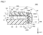
- FIG. 11 is a side see-through view of an antenna module according to a third embodiment.
- FIG. 8 is a plan view of the antenna module of FIG. 7 .
- FIG. 13 is a side see-through view of the antenna module according to the fourth embodiment.
- FIG. 13 is a side see-through view of the antenna module according to the fifth embodiment.
- 11 is a plan view of a
- the communication device 10 is, for example, a mobile terminal such as a mobile phone, a smartphone, or a tablet, or a personal computer equipped with a communication function.
- An example of the frequency band of radio waves used in the antenna module 100 according to the first embodiment is a millimeter wave band radio wave having a center frequency of, for example, 28 GHz, 39 GHz, or 60 GHz, but radio waves of other frequency bands are also applicable.
- the communication device 10 includes an antenna module 100 and a BBIC 200 that constitutes a baseband signal processing circuit.
- the antenna module 100 includes an RFIC 110 that supplies a high-frequency signal, and an antenna device 120.
- the communication device 10 upconverts a signal transmitted from the BBIC 200 to the antenna module 100 into a high-frequency signal and radiates the signal from the antenna device 120, and downconverts a high-frequency signal received by the antenna device 120 and processes the signal in the BBIC 200.
- the antenna device 120 includes a dielectric substrate 105 having two flat portions 130A and 130B. At least one radiating element is arranged on each substrate of the dielectric substrate 105. In FIG. 1, four radiating elements 121A are arranged on the flat portion 130A, and four radiating elements 121B are arranged on the flat portion 130B. However, the number of radiating elements arranged on each substrate is not limited to this. In addition, in FIG. 1, an example is shown in which the radiating elements are arranged in a one-dimensional array in a line on each substrate of the dielectric substrate, but the radiating elements may be arranged in a two-dimensional array on each substrate. Alternatively, a single radiating element may be arranged on each substrate. In the first embodiment, the radiating elements 121A and 121B are patch antennas having a substantially square flat plate shape.
- the RFIC 110 includes switches 111A to 111H, 113A to 113H, 117A, and 117B, power amplifiers 112AT to 112HT, low noise amplifiers 112AR to 112HR, attenuators 114A to 114H, phase shifters 115A to 115H, signal combiners/distributors 116A and 116B, mixers 118A and 118B, and amplifier circuits 119A and 119B.
- the switches 111A to 111D, 113A to 113D, 117A, power amplifiers 112AT to 112DT, low-noise amplifiers 112AR to 112DR, attenuators 114A to 114D, phase shifters 115A to 115D, signal combiner/distributor 116A, mixer 118A, and amplifier circuit 119A form a circuit for the high-frequency signal radiated from radiating element 121A of flat portion 130A.
- the configuration of the switches 111E-111H, 113E-113H, 117B, the power amplifiers 112ET-112HT, the low-noise amplifiers 112ER-112HR, the attenuators 114E-114H, the phase shifters 115E-115H, the signal combiner/distributor 116B, the mixer 118B, and the amplifier circuit 119B constitutes a circuit for the high-frequency signal radiated from the radiating element 121B of the flat portion 130B.
- switches 111A-111H and 113A-113H are switched to the power amplifiers 112AT-112HT, and switches 117A and 117B are connected to the transmitting amplifiers of amplifier circuits 119A and 119B.
- switches 111A-111H and 113A-113H are switched to the low-noise amplifiers 112AR-112HR, and switches 117A and 117B are connected to the receiving amplifiers of amplifier circuits 119A and 119B.
- the signal transmitted from the BBIC 200 is amplified by amplifier circuits 119A, 119B and up-converted by mixers 118A, 118B.
- the up-converted high-frequency transmission signal is split into four by signal combiners/distributors 116A, 116B, passes through the corresponding signal paths, and is fed to the different radiating elements 121A, 121B.
- signal combiners/distributors 116A, 116B passes through the corresponding signal paths, and is fed to the different radiating elements 121A, 121B.
- the directivity of the radio waves output from the radiating elements of each board can be adjusted.
- attenuators 114A-114D adjust the strength of the transmission signal.
- the received signals which are high-frequency signals received by each radiating element 121A, 121B, are transmitted to the RFIC 110 and are combined in the signal combiners/distributors 116A, 116B via four different signal paths.
- the combined received signals are down-converted in the mixers 118A, 118B, and further amplified in the amplifier circuits 119A, 119B before being transmitted to the BBIC 200.
- the RFIC 110 is formed, for example, as a one-chip integrated circuit component including the above circuit configuration.
- the devices switching, power amplifiers, low-noise amplifiers, attenuators, phase shifters
- corresponding to each of the radiating elements 121A, 121B in the RFIC 110 may be formed as one-chip integrated circuit components for each corresponding radiating element.
- Fig. 2 is a perspective view of the antenna module 100.
- Fig. 3 is a side see-through view of the antenna module 100 mounted on a mounting substrate 20.
- the antenna module 100 includes a connector 180, power supply wiring 171, 172, and ground electrodes GND1, GND2 in addition to the dielectric substrate 105, radiating elements 121A, 121B, and RFIC 110.
- the normal direction of flat portion 130A is the Z-axis direction
- the normal direction of flat portion 130B is the X-axis direction
- the arrangement direction of the radiating elements on each substrate is the Y-axis direction.
- the positive direction of the Z-axis in each figure may be referred to as the top side, and the negative direction as the bottom side.
- the dielectric substrate 105 is, for example, a low temperature co-fired ceramics (LTCC) multilayer substrate, a multilayer resin substrate formed by laminating multiple resin layers made of resins such as epoxy and polyimide, a multilayer resin substrate formed by laminating multiple resin layers made of liquid crystal polymer (LCP) having a lower dielectric constant, a multilayer resin substrate formed by laminating multiple resin layers made of fluorine-based resin, or a ceramic multilayer substrate other than LTCC.
- LCP liquid crystal polymer
- the dielectric substrate 105 does not necessarily have to have a multilayer structure and may be a single-layer substrate.
- the dielectric substrate 105 has a substantially L-shaped cross section, and includes a flat portion 130A having a plate shape whose normal direction is the Z-axis direction in FIGS. 2 and 3, a flat portion 130B having a plate shape whose normal direction is the X-axis direction in FIGS. 2 and 3, and a bent portion 135 connecting the two flat portions 130A and 130B.
- the flat portion 130B corresponds to the "first flat portion” of the present disclosure
- the flat portion 130A corresponds to the "second flat portion" of the present disclosure.
- the antenna module 100 four radiating elements are arranged in a row in the Y-axis direction on each of the two flat sections 130A, 130B.
- the radiating elements 121A, 121B are arranged so as to be exposed on the surfaces of the flat sections 130A, 130B, but the radiating elements 121A, 121B may also be arranged inside the flat sections 130A, 130B.
- the flat portion 130A has a generally rectangular shape, and four radiating elements 121A are arranged in a row in the Y-axis direction on its upper main surface 131.
- a SiP (System In Package) module 125 incorporating an RFIC 110 and a power module IC (not shown), as well as a connector 180, are connected to the lower main surface 132 side (the surface in the negative direction of the Z-axis) of the flat portion 130A.
- the flat portion 130A is mounted on the mounting substrate 20 by connecting the connector 180 to a connector 185 arranged on the surface 21 of the mounting substrate 20.
- the flat portion 130A may be mounted on the mounting substrate 20 by solder connection.
- a ground electrode GND2 is disposed on the inner layer of the main surface 132 side of the flat portion 130A that faces the mounting substrate 20, covering the entire surface of the flat portion 130A.
- the ground electrode GND2 extends from the flat portion 130A to the bent portion 135.
- a high-frequency signal is transmitted from the RFIC 110 in the SiP module 125 to the radiating element 121A of the flat portion 130A via a power supply line 171.
- the power supply line 171 is connected to a power supply point SP1 that is offset in the negative direction of the X-axis from the center of the radiating element 121A.
- radio waves with the polarization direction in the X-axis direction are radiated in the positive direction of the Z-axis.
- the flat portion 130B is connected to the bent portion 135 bent from the flat portion 130A, and is arranged so that its inner main surface 138 (the surface in the negative direction of the X-axis) faces the side surface 22 of the mounting substrate 20.
- the flat portion 130B is configured with a plurality of notches 136 formed in a dielectric substrate of a substantially rectangular shape, and the bent portion 135 is connected to the notches 136.
- a protruding portion 133 is formed that protrudes from the boundary portion 134 where the bent portion 135 and the flat portion 130B are connected in a direction toward the flat portion 130A along the flat portion 130B (i.e., in the positive direction of the Z-axis).
- the position of the protruding end of this protruding portion 133 is located in the positive direction of the Z-axis from the main surface 132 of the flat portion 130A.
- a radiating element 121B is arranged on the main surface 137 of the flat portion 130B in correspondence with the radiating element 121A arranged on the flat portion 130A.
- the radiating element 121B is not arranged on the protruding portion 133.
- the multiple radiating elements 121B are each arranged in line with the radiating element 121A in the X-axis direction.
- the flat portion 130B of the antenna module 100 has two regions in the normal direction (i.e., the X-axis direction). More specifically, it has a region RG1 (first region) to which the bent portion 135 is connected, and a region RG2 (second region) that is closer to the main surface 138 than the region RG1. In the antenna module 100, the regions RG1 and RG2 are integrally formed from the same material.
- the thickness of flat portion 130A (dimension in the Z-axis direction) is thicker than the thickness of region RG1 in flat portion 130B (dimension in the X-axis direction).
- the thickness of flat portion 130A is thinner than the thickness of flat portion 130B, i.e., the sum of the thicknesses of regions RG1 and RG2.
- a ground electrode GND1 is disposed on the inner layer on the main surface 138 side.
- the ground electrode GND1 is connected to the ground electrode GND2 disposed in the bent portion 135 by a via VG1 extending in the X-axis direction within the flat portion 130B.
- a high-frequency signal is transmitted from the RFIC 110 to the radiating element 121B of the flat portion 130B via the power supply line 172.
- the power supply line 172 is connected from the RFIC 110 to the radiating element 121B arranged on the flat portion 130B, passing through the inside of the dielectric of the flat portion 130A, the bent portion 135, and the flat portion 130B.
- the power supply line 172 is connected to a power supply point SP2 offset in the negative direction of the Y axis from the center of the radiating element 121B.
- the flat portion 130A is disposed facing the main surface on which the display is disposed, and the flat portion 130B is disposed facing the side surface of the housing.
- the L-shaped dielectric substrate 105 of the antenna module 100 as described above is formed by cutting out the boundary between the two flat portions 130A and 130B in a flat, one-piece substrate, and then bending the flat portion 130B relative to the flat portion 130A.
- the gap between the mounting substrate 20 and the housing narrows, limiting the dimension in the radiation direction of the radio waves from the flat portion 130B (i.e., the positive direction of the X-axis in Figures 2 and 3). Therefore, it is necessary to shorten the dimension from the bent portion 135 to the main surface 137 in the radiation direction in the flat portion 130B by cutting or the like. If this is done, the distance between the radiating element 121B and the ground electrode GND1 in the flat portion 130B cannot be sufficiently secured, and the bandwidth of the radio waves radiated from the radiating element 121B may be narrowed.
- the gap between flat portion 130A and region RG1 of flat portion 130B caused by bend 135 is utilized to add region RG2 to flat portion 130B to increase the dimension on the main surface 138 side (i.e., the thickness in the negative direction of the X-axis in FIG. 3).
- This region RG2 ensures the distance between radiating element 121B and ground electrode GND1 in flat portion 130B while reducing the overall dimension of the antenna module in the X-axis direction. Therefore, by using a configuration like antenna module 100, it is possible to achieve miniaturization while suppressing degradation of the antenna characteristics.
- the distance t2 between the radiating element 121B and the ground electrode GND1 in the flat portion 130B is set to be equal to or greater than the distance t1 between the radiating element 121A and the ground electrode GND2 in the flat portion 130A (t1 ⁇ t2). Note that if no radiating element is disposed in the flat portion 130A, the distance between the main surface 131 and the ground electrode GND2 in the flat portion 130A is set to t1.
- the distance t2 between the radiating element 121B and the ground electrode GND1 in the flat portion 130B is set to be equal to or less than the distance t3 from the main surface 131 of the flat portion 130A to the underside of the SiP module 125 (t2 ⁇ t3).
- the dielectric substrate 105 may be formed, for example, by preparing a flat dielectric substrate of a predetermined thickness, and then bending the substrate by removing, for example, the back side of the portion corresponding to flat portion 130A and the front side of the portion corresponding to flat portion 130B.
- a member may be prepared in which the number of laminated dielectric layers on the upper surface side is increased for the portion corresponding to flat portion 130A, and the number of laminated dielectric layers on the lower surface side is increased for the portion corresponding to flat portion 130B, and then bending the substrate.
- the ground electrodes GND1 and GND2 may be connected by a sputter shield formed on the side of the region RG2 instead of the via VG1 in the flat portion 130B.
- the “radiating element 121B” and the “radiating element 121A” in the first embodiment correspond to the “first radiating element” and the “second radiating element” in the present disclosure, respectively.
- the “ground electrode GND1” and the “ground electrode GND2” in the first embodiment correspond to the “first ground electrode” and the “second ground electrode” in the present disclosure, respectively.
- the “principal surface 131" and the “principal surface 132" in the first embodiment correspond to the “first principal surface” and the “second principal surface” of the first flat portion in the present disclosure, respectively.
- the “principal surface 137" and the “principal surface 138" in the first embodiment correspond to the "first principal surface” and the “second principal surface” of the second flat portion in the present disclosure, respectively.
- the “via VG1" in the first embodiment corresponds to the “first via” in the present disclosure.
- the “SiP module 125” in the first embodiment corresponds to the "power supply circuit” in the present disclosure.
- FIG. 4 is a side perspective view of an antenna module 100A according to the second embodiment.
- the flat portion 130B of the dielectric substrate 105 includes only the above-mentioned region RG1.
- a dielectric substrate 190 formed of an independent member is attached as region RG2 to the main surface of region RG1 in the negative direction of the X-axis.
- the flat portion 130B is attached to the dielectric substrate 190 using solder or a conductive adhesive.
- the other configurations in FIG. 4 are basically the same as those of the antenna module 100 shown in FIG. 3, and the description of the elements that overlap with FIG. 3 will not be repeated.
- the dielectric substrate 190 is a single-layer or multi-layer substrate made of ceramics or resin, similar to the dielectric substrate 105.
- the dielectric substrate 190 has a flat plate shape, and a ground electrode GND1 is disposed over the entire surface of a specific dielectric layer inside.
- the ground electrode GND1 is connected to the ground electrode GND2, which extends from the flat portion 130A to the bent portion 135, by a via VG1.
- the dielectric substrate 190 has a generally rectangular shape, for example as shown in FIG. 5, and is disposed corresponding to each protrusion 133 of the flat portion 130B. In other words, the dielectric substrate 190 is disposed in the portion between the two bent portions 135, and is not disposed in the portion corresponding to the notch 136 of the flat portion 130B. The end of the dielectric substrate 190 in the positive direction of the Z axis extends to a position overlapping with the flat portion 130A.
- radiating element 121B is positioned so as to overlap protrusion 133 on flat portion 130B. That is, compared to antenna module 100 of embodiment 1, radiating element 121B is positioned at a position offset in the positive direction of the Z axis on flat portion 130B. Accordingly, the dimension of flat portion 130B in the Z axis direction is shorter than that of antenna module 100. By positioning radiating element 121B in this manner, the dimension of the entire antenna module in the Z axis direction can be reduced, resulting in a lower profile.
- the substrate arranged as region RG2 may be formed as an integral structure like dielectric substrate 190A in antenna module 100B in FIG. 6.
- dielectric substrate 190A When viewed in a plan view from the X-axis direction, dielectric substrate 190A has a shape roughly similar to flat portion 130B, and has a configuration in which multiple protrusions are formed in a rectangular shape. Dielectric substrate 190A is arranged such that the protrusions of dielectric substrate 190A overlap the protrusions 133 of flat portion 130B.
- ground electrode GND1 can be made larger than in the case of dielectric substrate 190, improving the antenna characteristics.
- the ground electrode GND1 is smaller than in the case of dielectric substrate 190A, slightly reducing the improvement in antenna characteristics, but the shape precision of each substrate is somewhat relaxed.
- the distance between the radiating element 121B and the ground electrode GND1 in the flat portion 130B can be secured even if the thickness of the region RG1 is reduced, so that the reduction in bandwidth can be suppressed. Therefore, it is possible to achieve miniaturization while suppressing the deterioration of the antenna characteristics.
- the dielectric substrate 105 does not have to be an integral structure.
- the dielectric substrate 105 may be formed by attaching a flat dielectric substrate corresponding to the flat portions 130A and 130B to a flexible substrate.
- FIG. 7 is a side perspective view of an antenna module 100C according to embodiment 3.
- FIG. 8 is a plan view of the antenna module 100C of FIG. 7.
- antenna module 100C has a configuration in which dielectric substrate 190B, which is formed as a separate member from flat portion 130B, is disposed on the back side of flat portion 130B, like antenna module 100A of embodiment 2.
- Dielectric substrate 190B may have a separate structure like dielectric substrate 190, or may have an integrated structure like dielectric substrate 190A.
- Figure 7 shows a cross section of a portion without bent portion 135 connecting flat portion 130A and flat portion 130B.
- a ground electrode GND1 is disposed over the entire surface of a specific dielectric layer inside the substrate. Furthermore, in the dielectric substrate 190B, a ground electrode GND3 is disposed, extending from the ground electrode GND1 toward the flat portion 130A (i.e., the negative direction of the X-axis). As shown in FIG. 8, when viewed in a plan view from the Z-axis direction, the ground electrode GND3 is composed of multiple vias VG2. The vias VG2 are disposed at least in positions facing each of the radiating elements 121A.
- the via VG2 is disposed at approximately the same position as the ground electrode GND2 in the Z-axis direction, and is not directly connected to the ground electrode GND2.
- the distance D2 in the X-axis direction between the radiating element 121A and the via VG2 is shorter than the distance D1 in the X-axis direction between the end of the ground electrode GND2 in the negative direction of the X-axis and the radiating element 121B.
- the radiating element 121B is disposed in the flat portion 130A, offset toward the flat portion 130B, i.e., in the positive direction of the X-axis.
- the radiating element 121B when the radiating element 121B is offset in the polarization direction with respect to the flat portion 130A, the area of the ground electrode GND2 in the positive direction of the X-axis may be insufficient compared to the radiating element 121A, and the antenna characteristics may be degraded.
- the via VG2 since the via VG2 is connected to the ground electrode GND2 through the ground electrode GND1 and the via VG1, it also functions as the ground electrode of the radiating element 121A of the flat portion 130A. As a result, even if the radiating element 121A is offset toward the flat portion 130B on the flat portion 130A, the area of the ground electrode in the polarization direction can be secured, so that the degradation of the antenna characteristics can be suppressed.
- the dimension of the entire antenna module in the X-axis direction can be shortened, and further miniaturization can be achieved.
- the ground electrode GND3 is described as being composed of multiple vias VG2, but a flat electrode may also be used as the ground electrode GND3.
- ground electrode GND3 in the third embodiment corresponds to the "third ground electrode” in this disclosure.
- via VG2 in the third embodiment corresponds to the "second via” in this disclosure.
- FIG. 9 is a side perspective view of an antenna module 100D according to the fourth embodiment.
- the antenna module 100D has a configuration in which a heat dissipation member 195 is added to the configuration of the antenna module 100 in FIG. 3.
- the thickness (dimension in the X-axis direction) of region RG2 of flat portion 130B is made thicker than that in FIG. 3, and heat dissipation member 195 is disposed over the entire surface of main surface 138.
- the heat dissipation member 195 is made of a material with a relatively high thermal conductivity, such as metal. A part of the heat dissipation member 195 is in contact with the outer periphery of the SiP module 125. If a conductive shield electrode 126 that covers the outer periphery is arranged on the SiP module 125, the heat dissipation member 195 is arranged so as to be in contact with the shield electrode 126.
- circuits such as the RFIC 110 included in the SiP module 125 generate heat as the circuit operates. If the temperature of the electronic elements in the circuit rises due to this heat generation, this can cause a deterioration in the antenna characteristics.
- the heat dissipation member 195 which is made of a material with high thermal conductivity, into contact with the SiP module 125, the heat generated within the SiP module 125 can be efficiently dissipated using the heat dissipation member 195. Therefore, failure of the SiP module 125 due to heat generation can be suppressed.
- FIG. 10 is a side perspective view of an antenna module 100E according to the fifth embodiment.
- FIG. 11 is a plan view of the flat portion 130B of the antenna module 100E of FIG. 11.
- the cutout portion 136 (recess) formed at the connection portion of the flat portion 130B with the bent portion 135 is filled with a dielectric member 130C.
- the dielectric member 130C is a generally flat plate-shaped member made of ceramic or resin, similar to the dielectric substrate 105.
- the surface of the dielectric member 130C in the positive direction of the X-axis is flat with no step with the main surface 137 of the flat portion 130B.
- the surface of the dielectric member 130C in the negative direction of the X-axis has a shape corresponding to the bent portion 135.
- a ground electrode GND4 is disposed over the entire surface of a specific dielectric layer inside the dielectric member 130C.
- the ground electrode GND4 is electrically connected to the ground electrode GND2 in the bent portion 135 and/or the ground electrode GND1 in the flat portion 130B by a connecting member (not shown).
- the flat portion 130B has a partial cutout 136 formed at the connection with the bent portion 135, and there is no ground electrode in that portion.
- the arrangement of the ground electrode with respect to the radiating element 121B is non-uniform, and this non-uniformity can degrade the antenna characteristics.
- the cutout 136 is filled with a dielectric member 130C including a ground electrode GND4.
- the position of the ground electrode GND4 in the X-axis direction does not coincide with the position of the ground electrode GND1 in the X-axis direction, but by arranging the ground electrode GND4, the area of the ground electrode relative to the radiating element 121B is expanded, and the unevenness of the ground electrode is mitigated. Therefore, in the antenna module 100E, the antenna characteristics can be improved compared to when the dielectric member 130C is not arranged.
- ground electrode GND4 in embodiment 5 corresponds to the "fourth ground electrode” in this disclosure.
- An antenna module includes a dielectric substrate, a first radiating element, a first ground electrode, and a second ground electrode.
- the dielectric substrate includes a first flat portion and a second flat portion having different normal directions, and a bent portion connecting the first flat portion and the second flat portion.
- the first radiating element has a flat plate shape and is disposed on the first flat portion.
- the first ground electrode is disposed facing the first radiating element on the first flat portion.
- the second ground electrode is disposed on the second flat portion.
- the first flat portion and the second flat portion each have a first main surface and a second main surface that face each other.
- the first flat portion includes a first region to which the bent portion is connected, and a second region disposed on the second flat portion side of the first region.
- the dimension of the second flat portion in the second direction is greater than the dimension of the first region in the first direction and is smaller than the sum of the dimensions of the first region and the second region in the first direction.
- the distance between the first radiating element and the first ground electrode in the first flat portion is greater than the distance between the first main surface of the second flat portion and the second ground electrode.
- the second ground electrode extends from the second flat portion through the bent portion to the first flat portion.
- the antenna module further includes a first via in the second flat portion that connects the first ground electrode and the second ground electrode.
- the first ground electrode is disposed in the second region.
- the first and second regions are integrally constructed from the same material.
- the second region is made of a separate material from the first region.
- the first region has a protrusion that protrudes partially along the first flat portion toward the second flat portion beyond the boundary between the bent portion and the first flat portion.
- the bent portion is connected to the first region at a position in the first region where there is no protrusion.
- At least a portion of the first radiating element is disposed on the protrusion.
- the second region is also disposed on the protrusion.
- the first ground electrode is also disposed on the protruding portion.
- the second region is positioned such that the end of the second region in the second direction is positioned to overlap the second flat portion.
- the antenna module described in Item 9 further includes a second radiating element and a third ground electrode.
- the second radiating element faces the second ground electrode in the second flat portion and is disposed closer to the first main surface of the second flat portion than the second ground electrode.
- the third ground electrode is disposed in the second region from the second ground electrode toward the second flat portion.
- the third ground electrode is disposed at the position of the second ground electrode in the second direction.
- the third ground electrode includes at least one second via that faces the second radiating element when viewed in a planar view from the second direction.
- the first direction and the second direction are perpendicular to each other.
- a feeding point is disposed at a position offset in the first direction from the center of the second radiating element.
- the second region is composed of multiple members.
- the antenna module described in any one of paragraphs 1 to 15 further includes a power supply circuit mounted on the second main surface of the second flat portion, and a heat dissipation member disposed on the second main surface of the first flat portion. The heat dissipation member is in contact with the power supply circuit.
- the power supply circuit includes a shield electrode that covers the outer periphery of the power supply circuit.
- the heat dissipation member is in contact with the shield electrode.
- the antenna module described in any one of paragraphs 1 to 17 further includes a dielectric member disposed in a recess formed in the connection portion of the first flat portion with the bent portion, and a fourth ground electrode disposed in the dielectric member and connected to the second ground electrode.
- An antenna module includes a dielectric substrate, a first radiating element, a first ground electrode, a second ground electrode, a dielectric member, and a fourth ground electrode.
- the dielectric substrate includes a first flat portion and a second flat portion having different normal directions, and a bent portion connecting the first flat portion and the second flat portion.
- the first radiating element has a flat plate shape and is disposed on the first flat portion.
- the first ground electrode is disposed on the first flat portion so as to face the first radiating element.
- the second ground electrode is disposed on the second flat portion.
- the dielectric member is disposed in a recess formed at the connection portion of the first flat portion with the bent portion.
- the fourth ground electrode is disposed on the dielectric member and is connected to the second ground electrode.
- a communication device is equipped with an antenna module described in any one of clauses 1 to 19.
Landscapes
- Details Of Aerials (AREA)
Priority Applications (1)
| Application Number | Priority Date | Filing Date | Title |
|---|---|---|---|
| JP2025519371A JP7827215B2 (ja) | 2023-05-10 | 2024-04-22 | アンテナモジュールおよびそれを搭載した通信装置 |
Applications Claiming Priority (2)
| Application Number | Priority Date | Filing Date | Title |
|---|---|---|---|
| JP2023077754 | 2023-05-10 | ||
| JP2023-077754 | 2023-05-10 |
Publications (1)
| Publication Number | Publication Date |
|---|---|
| WO2024232251A1 true WO2024232251A1 (ja) | 2024-11-14 |
Family
ID=93430104
Family Applications (1)
| Application Number | Title | Priority Date | Filing Date |
|---|---|---|---|
| PCT/JP2024/015720 Ceased WO2024232251A1 (ja) | 2023-05-10 | 2024-04-22 | アンテナモジュールおよびそれを搭載した通信装置 |
Country Status (2)
| Country | Link |
|---|---|
| JP (1) | JP7827215B2 (https=) |
| WO (1) | WO2024232251A1 (https=) |
Citations (4)
| Publication number | Priority date | Publication date | Assignee | Title |
|---|---|---|---|---|
| JP2019004241A (ja) * | 2017-06-13 | 2019-01-10 | Tdk株式会社 | アンテナ装置及びこれを備える回路基板 |
| WO2020090391A1 (ja) * | 2018-10-31 | 2020-05-07 | 株式会社村田製作所 | 配線基板、アンテナモジュール、および通信装置 |
| WO2020170722A1 (ja) * | 2019-02-20 | 2020-08-27 | 株式会社村田製作所 | アンテナモジュールおよびそれを搭載した通信装置、ならびにアンテナモジュールの製造方法 |
| US20210329777A1 (en) * | 2020-04-16 | 2021-10-21 | Samsung Electro-Mechanics Co., Ltd. | Printed circuit board and antenna module comprising the same |
-
2024
- 2024-04-22 WO PCT/JP2024/015720 patent/WO2024232251A1/ja not_active Ceased
- 2024-04-22 JP JP2025519371A patent/JP7827215B2/ja active Active
Patent Citations (4)
| Publication number | Priority date | Publication date | Assignee | Title |
|---|---|---|---|---|
| JP2019004241A (ja) * | 2017-06-13 | 2019-01-10 | Tdk株式会社 | アンテナ装置及びこれを備える回路基板 |
| WO2020090391A1 (ja) * | 2018-10-31 | 2020-05-07 | 株式会社村田製作所 | 配線基板、アンテナモジュール、および通信装置 |
| WO2020170722A1 (ja) * | 2019-02-20 | 2020-08-27 | 株式会社村田製作所 | アンテナモジュールおよびそれを搭載した通信装置、ならびにアンテナモジュールの製造方法 |
| US20210329777A1 (en) * | 2020-04-16 | 2021-10-21 | Samsung Electro-Mechanics Co., Ltd. | Printed circuit board and antenna module comprising the same |
Also Published As
| Publication number | Publication date |
|---|---|
| JP7827215B2 (ja) | 2026-03-10 |
| JPWO2024232251A1 (https=) | 2024-11-14 |
Similar Documents
| Publication | Publication Date | Title |
|---|---|---|
| JP7014287B2 (ja) | アンテナモジュールおよびそれを搭載した通信装置 | |
| US11171421B2 (en) | Antenna module and communication device equipped with the same | |
| JP7283585B2 (ja) | アンテナモジュール | |
| WO2019026595A1 (ja) | アンテナモジュールおよび通信装置 | |
| US20250260157A1 (en) | Antenna module and communication apparatus including the same | |
| CN115868084A (zh) | 天线模块和搭载该天线模块的通信装置 | |
| WO2023037806A1 (ja) | アンテナモジュールおよびそれを搭載した通信装置 | |
| WO2021059671A1 (ja) | アンテナモジュールおよびそれを備える通信装置 | |
| WO2022138045A1 (ja) | アンテナモジュールおよびそれを搭載した通信装置 | |
| JP6798656B1 (ja) | アンテナモジュールおよびそれを搭載した通信装置 | |
| WO2023214473A1 (ja) | 伝送線路、ならびに、それを含むアンテナモジュールおよび通信装置 | |
| WO2023095643A1 (ja) | アンテナモジュール、およびそれを搭載した通信装置 | |
| JP7827215B2 (ja) | アンテナモジュールおよびそれを搭載した通信装置 | |
| JP7283623B2 (ja) | アンテナモジュールおよびそれを搭載した通信装置 | |
| WO2023157450A1 (ja) | アンテナモジュールおよびそれを搭載した通信装置 | |
| WO2024075334A1 (ja) | アンテナモジュールおよびそれを搭載した通信装置 | |
| JP7810257B2 (ja) | アンテナモジュール | |
| CN221353166U (zh) | 天线模块以及搭载有天线模块的通信装置 | |
| US12620714B2 (en) | Antenna module | |
| WO2025033014A1 (ja) | アンテナモジュール、基板接続構造体および通信装置 | |
| US20250183555A1 (en) | Antenna module and communication device equipped with the same | |
| JP7852743B2 (ja) | アンテナモジュールおよびそれを搭載した通信装置 | |
| US20260031542A1 (en) | Antenna device and communication device including same | |
| US20260011921A1 (en) | Substrate structural unit, antenna module, and communication device | |
| WO2025150415A1 (ja) | アンテナモジュールおよびそれを搭載した通信装置、ならびに、アンテナモジュールの製造方法 |
Legal Events
| Date | Code | Title | Description |
|---|---|---|---|
| 121 | Ep: the epo has been informed by wipo that ep was designated in this application |
Ref document number: 24803364 Country of ref document: EP Kind code of ref document: A1 |
|
| ENP | Entry into the national phase |
Ref document number: 2025519371 Country of ref document: JP Kind code of ref document: A |
|
| WWE | Wipo information: entry into national phase |
Ref document number: 2025519371 Country of ref document: JP |
|
| NENP | Non-entry into the national phase |
Ref country code: DE |