WO2024232191A1 - 作業機械及びバッテリパックの交換方法 - Google Patents
作業機械及びバッテリパックの交換方法 Download PDFInfo
- Publication number
- WO2024232191A1 WO2024232191A1 PCT/JP2024/013320 JP2024013320W WO2024232191A1 WO 2024232191 A1 WO2024232191 A1 WO 2024232191A1 JP 2024013320 W JP2024013320 W JP 2024013320W WO 2024232191 A1 WO2024232191 A1 WO 2024232191A1
- Authority
- WO
- WIPO (PCT)
- Prior art keywords
- battery pack
- vehicle body
- battery
- work machine
- replacement
- Prior art date
- Legal status (The legal status is an assumption and is not a legal conclusion. Google has not performed a legal analysis and makes no representation as to the accuracy of the status listed.)
- Ceased
Links
Images



Classifications
-
- B—PERFORMING OPERATIONS; TRANSPORTING
- B60—VEHICLES IN GENERAL
- B60L—PROPULSION OF ELECTRICALLY-PROPELLED VEHICLES; SUPPLYING ELECTRIC POWER FOR AUXILIARY EQUIPMENT OF ELECTRICALLY-PROPELLED VEHICLES; ELECTRODYNAMIC BRAKE SYSTEMS FOR VEHICLES IN GENERAL; MAGNETIC SUSPENSION OR LEVITATION FOR VEHICLES; MONITORING OPERATING VARIABLES OF ELECTRICALLY-PROPELLED VEHICLES; ELECTRIC SAFETY DEVICES FOR ELECTRICALLY-PROPELLED VEHICLES
- B60L53/00—Methods of charging batteries, specially adapted for electric vehicles; Charging stations or on-board charging equipment therefor; Exchange of energy storage elements in electric vehicles
- B60L53/80—Exchanging energy storage elements, e.g. removable batteries
-
- B—PERFORMING OPERATIONS; TRANSPORTING
- B60—VEHICLES IN GENERAL
- B60L—PROPULSION OF ELECTRICALLY-PROPELLED VEHICLES; SUPPLYING ELECTRIC POWER FOR AUXILIARY EQUIPMENT OF ELECTRICALLY-PROPELLED VEHICLES; ELECTRODYNAMIC BRAKE SYSTEMS FOR VEHICLES IN GENERAL; MAGNETIC SUSPENSION OR LEVITATION FOR VEHICLES; MONITORING OPERATING VARIABLES OF ELECTRICALLY-PROPELLED VEHICLES; ELECTRIC SAFETY DEVICES FOR ELECTRICALLY-PROPELLED VEHICLES
- B60L50/00—Electric propulsion with power supplied within the vehicle
- B60L50/50—Electric propulsion with power supplied within the vehicle using propulsion power supplied by batteries or fuel cells
- B60L50/60—Electric propulsion with power supplied within the vehicle using propulsion power supplied by batteries or fuel cells using power supplied by batteries
- B60L50/64—Constructional details of batteries specially adapted for electric vehicles
-
- B—PERFORMING OPERATIONS; TRANSPORTING
- B60—VEHICLES IN GENERAL
- B60L—PROPULSION OF ELECTRICALLY-PROPELLED VEHICLES; SUPPLYING ELECTRIC POWER FOR AUXILIARY EQUIPMENT OF ELECTRICALLY-PROPELLED VEHICLES; ELECTRODYNAMIC BRAKE SYSTEMS FOR VEHICLES IN GENERAL; MAGNETIC SUSPENSION OR LEVITATION FOR VEHICLES; MONITORING OPERATING VARIABLES OF ELECTRICALLY-PROPELLED VEHICLES; ELECTRIC SAFETY DEVICES FOR ELECTRICALLY-PROPELLED VEHICLES
- B60L50/00—Electric propulsion with power supplied within the vehicle
- B60L50/50—Electric propulsion with power supplied within the vehicle using propulsion power supplied by batteries or fuel cells
- B60L50/60—Electric propulsion with power supplied within the vehicle using propulsion power supplied by batteries or fuel cells using power supplied by batteries
- B60L50/66—Arrangements of batteries
-
- E—FIXED CONSTRUCTIONS
- E02—HYDRAULIC ENGINEERING; FOUNDATIONS; SOIL SHIFTING
- E02F—DREDGING; SOIL-SHIFTING
- E02F9/00—Component parts of dredgers or soil-shifting machines, not restricted to one of the kinds covered by groups E02F3/00 - E02F7/00
- E02F9/08—Superstructures; Supports for superstructures
- E02F9/0858—Arrangement of component parts installed on superstructures not otherwise provided for, e.g. electric components, fenders, air-conditioning units
-
- E—FIXED CONSTRUCTIONS
- E02—HYDRAULIC ENGINEERING; FOUNDATIONS; SOIL SHIFTING
- E02F—DREDGING; SOIL-SHIFTING
- E02F9/00—Component parts of dredgers or soil-shifting machines, not restricted to one of the kinds covered by groups E02F3/00 - E02F7/00
- E02F9/20—Drives; Control devices
- E02F9/2025—Particular purposes of control systems not otherwise provided for
- E02F9/2054—Fleet management
-
- E—FIXED CONSTRUCTIONS
- E02—HYDRAULIC ENGINEERING; FOUNDATIONS; SOIL SHIFTING
- E02F—DREDGING; SOIL-SHIFTING
- E02F9/00—Component parts of dredgers or soil-shifting machines, not restricted to one of the kinds covered by groups E02F3/00 - E02F7/00
- E02F9/20—Drives; Control devices
- E02F9/2058—Electric or electro-mechanical or mechanical control devices of vehicle sub-units
- E02F9/2091—Control of energy storage means for electrical energy, e.g. battery or capacitors
-
- E—FIXED CONSTRUCTIONS
- E02—HYDRAULIC ENGINEERING; FOUNDATIONS; SOIL SHIFTING
- E02F—DREDGING; SOIL-SHIFTING
- E02F9/00—Component parts of dredgers or soil-shifting machines, not restricted to one of the kinds covered by groups E02F3/00 - E02F7/00
- E02F9/26—Indicating devices
- E02F9/264—Sensors and their calibration for indicating the position of the work tool
- E02F9/265—Sensors and their calibration for indicating the position of the work tool with follow-up actions (e.g. control signals sent to actuate the work tool)
-
- B—PERFORMING OPERATIONS; TRANSPORTING
- B60—VEHICLES IN GENERAL
- B60L—PROPULSION OF ELECTRICALLY-PROPELLED VEHICLES; SUPPLYING ELECTRIC POWER FOR AUXILIARY EQUIPMENT OF ELECTRICALLY-PROPELLED VEHICLES; ELECTRODYNAMIC BRAKE SYSTEMS FOR VEHICLES IN GENERAL; MAGNETIC SUSPENSION OR LEVITATION FOR VEHICLES; MONITORING OPERATING VARIABLES OF ELECTRICALLY-PROPELLED VEHICLES; ELECTRIC SAFETY DEVICES FOR ELECTRICALLY-PROPELLED VEHICLES
- B60L2200/00—Type of vehicles
- B60L2200/40—Working vehicles
-
- E—FIXED CONSTRUCTIONS
- E02—HYDRAULIC ENGINEERING; FOUNDATIONS; SOIL SHIFTING
- E02F—DREDGING; SOIL-SHIFTING
- E02F9/00—Component parts of dredgers or soil-shifting machines, not restricted to one of the kinds covered by groups E02F3/00 - E02F7/00
- E02F9/20—Drives; Control devices
- E02F9/2025—Particular purposes of control systems not otherwise provided for
- E02F9/205—Remotely operated machines, e.g. unmanned vehicles
-
- Y—GENERAL TAGGING OF NEW TECHNOLOGICAL DEVELOPMENTS; GENERAL TAGGING OF CROSS-SECTIONAL TECHNOLOGIES SPANNING OVER SEVERAL SECTIONS OF THE IPC; TECHNICAL SUBJECTS COVERED BY FORMER USPC CROSS-REFERENCE ART COLLECTIONS [XRACs] AND DIGESTS
- Y02—TECHNOLOGIES OR APPLICATIONS FOR MITIGATION OR ADAPTATION AGAINST CLIMATE CHANGE
- Y02T—CLIMATE CHANGE MITIGATION TECHNOLOGIES RELATED TO TRANSPORTATION
- Y02T10/00—Road transport of goods or passengers
- Y02T10/60—Other road transportation technologies with climate change mitigation effect
- Y02T10/70—Energy storage systems for electromobility, e.g. batteries
Definitions
- This disclosure relates to a work machine and a method for replacing a battery pack.
- the present disclosure aims to replace the battery pack of a work machine.
- a work machine in accordance with the present disclosure, includes a vehicle body, a work implement connected to the front of the vehicle body, a battery connector disposed inside the vehicle body, and an exchange device that protrudes from the vehicle body and exchanges a battery pack attached to the battery connector.
- the battery pack of the work machine is replaced.
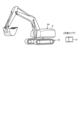
- FIG. 1 is a diagram showing a management system for a work machine according to an embodiment.
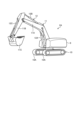
- FIG. 2 is a view showing the shovel according to the embodiment, seen from the left front.
- FIG. 3 is a view of the shovel according to the embodiment as viewed from above.
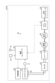
- FIG. 4 is a diagram showing a control system for a shovel according to an embodiment.
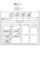
- FIG. 5 is a block diagram showing an in-vehicle controller according to the embodiment.
- FIG. 6 is a diagram for explaining the replacement operation of the battery pack 31 according to the embodiment.
- FIG. 7 is a diagram for explaining the operation of the exchange device according to the embodiment.
- FIG. 8 is a diagram for explaining the operation of the exchange device according to the embodiment.
- FIG. 9 is a diagram for explaining the operation of the exchange device according to the embodiment.
- FIG. 10 is a flowchart showing a method for replacing a battery pack according to the embodiment.
- Fig. 1 is a diagram showing a management system 1 for a work machine 2 according to an embodiment.
- the management system 1 manages the work machines 2 that operate at a work site 3.
- the work machines 2 are electric work machines that are powered by a battery pack and an electric motor.
- a plurality of work machines 2 are present at the work site 3.
- the work machines 2 present at the work site 3 include a shovel 2A, a bulldozer 2B, and a dump truck 2C.
- no operator is on board the work machine 2.
- the work machine 2 is remotely controlled.
- a remote control room 4 is installed outside the work machine 2.
- the remote control room 4 is installed in a remote location from the work site 3.
- An information terminal 5 and a remote control device 6 for remotely controlling the work machine 2 are each disposed in the remote control room 4.
- the information terminal 5 and the remote control device 6 each exist outside the work machine 2.
- the information terminal 5 includes a computer system disposed in the remote control room 4.
- the remote control device 6 is operated by an operator in the remote control room 4. When operated by the operator, the remote control device 6 generates an operation signal for remotely operating the work machine 2. The operation signal generated in the remote control device 6 is input to the information terminal 5. The information terminal 5 generates a remote operation command based on the operation signal from the remote control device 6. The information terminal 5 transmits the remote operation command to the work machine 2 via the communication system 7.
- the work machine 2 operates based on remote control commands transmitted from an information terminal 5 located outside the work machine 2. At least one of the work machine 2 and the work site 3 is provided with a camera that captures image data of the work site 3. The image data of the work site 3 is transmitted to the information terminal 5 via the communication system 7 and displayed on the display device of the information terminal 5. The operator can operate the remote control device 6 while checking the image data of the work site 3.
- the communication system 7 may include a public communication line or a specific communication line. Examples of the communication system 7 include a mobile phone communication network or a satellite communication network. The communication system 7 may include the Internet or a local area network.
- the management system 1 has a management server 8.
- the management server 8 includes a computer system.
- the management server 8 can communicate with the work machine 2 via the communication system 7.
- the management server 8 collects operation data of the work machine 2.
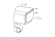
- the management server 8 outputs control commands to the work machine 2.
- [Working Machine] 2 is a view showing the shovel 2A according to the embodiment from the left front.
- the shovel 2A has a revolving body 9, a traveling body 10, a work machine 11, and a work machine cylinder 12.
- the rotating body 9 is the vehicle body of the shovel 2A.
- the running body 10 is the running device of the shovel 2A.
- the running body 10 supports the rotating body 9.
- the rotating body 9 is supported by the running body 10 so that it can rotate.
- the rotating body 9 is positioned above the running body 10.
- the running body 10 runs while supporting the rotating body 9.
- the running body 10 has a pair of tracks 10A.
- the shovel 2A runs as the tracks 10A rotate.
- the work machine 11 is connected to the front of the rotating body 9.
- the work machine 11 includes a boom 11A connected to the front of the rotating body 9, an arm 11B connected to the boom 11A, and a bucket 11C connected to the arm 11B.
- the work machine cylinder 12 includes a boom cylinder 12A that operates the boom 11A, an arm cylinder 12B that operates the arm 11B, and a bucket cylinder 12C that operates the bucket 11C.
- FIG. 3 is a top view of the shovel 2A according to the embodiment.
- FIG. 3 is a cutaway view of a portion of the shovel 2A.
- the shovel 2A has a battery connector 65 disposed inside the rotating body 9.
- a battery pack 31 is attached to the battery connector 65.
- the battery pack 31 is a power source for the shovel 2A.
- the battery pack 31 includes a plurality of cell batteries.
- the cell batteries include secondary batteries.
- the cell batteries include lithium ion batteries (LiB: Lithium ion Battery).
- the battery pack 31 is attached to and detached from the battery connector 65. Multiple battery packs 31 are attached to the battery connector 65.
- the battery connector 65 is long in the vehicle width direction (left-right direction) of the rotating body 9.
- two battery packs 31 are attached to the battery connector 65.
- the two battery packs 31 are arranged in the vehicle width direction. Note that the number of battery packs 31 attached to the battery connector 65 may be one, or any number of three or more.
- the excavator 2A is equipped with an exchange device 66 that exchanges the battery pack 31 attached to the battery connector 65.
- the exchange device 66 protrudes from the rotating body 9 and exchanges the battery pack 31 attached to the battery connector 65.
- Control System 4 is a diagram showing a control system 30 of the shovel 2A according to the embodiment.
- the shovel 2A has the control system 30.
- the control system 30 has a battery pack 31, a battery connector 65, an exchange device 66, a DC/DC converter 33, an inverter 34, an electric motor 35, a hydraulic pump 36, a main valve 37, a hydraulic actuator 38, an on-board controller 40, a battery sensor 41, a position sensor 42, and a communication device 43.
- the battery pack 31 is attached to and detached from the battery connector 65.
- the battery pack 31 has a power supply terminal.
- the battery connector 65 has a power receiving terminal.
- the replacement device 66 replaces the battery pack 31 attached to the battery connector 65.
- the replacement device 66 can remove the battery pack 31 from the battery connector 65.
- the replacement device 66 can transport the battery pack 31 removed from the battery connector 65 to the outside of the rotating body 9.
- the replacement device 66 can attach the battery pack 31 to the battery connector 65.
- the replacement device 66 can transport the battery pack 31 attached to the battery connector 65 into the inside of the rotating body 9.
- the DC/DC converter 33 boosts the voltage from the battery pack 31.
- the DC/DC converter 33 supplies direct current from the battery pack 31 to the inverter 34.
- the inverter 34 converts the direct current from the DC/DC converter 33 into three-phase alternating current and supplies it to the electric motor 35.
- the electric motor 35 is driven based on the three-phase alternating current supplied from the inverter 34.
- the electric motor 35 is the power source for the shovel 2A.
- the electric motor 35 is driven by power from the battery pack 31.
- the hydraulic pump 36 is driven by an electric motor 35.
- the hydraulic pump 36 discharges hydraulic oil.
- the hydraulic oil discharged from the hydraulic pump 36 is supplied to the hydraulic actuator 38 via a main valve 37.
- the hydraulic actuator 38 of the excavator 2A includes a work machine cylinder 12.
- an electric actuator may be provided in the excavator 2A instead of the hydraulic actuator 38.
- the work machine cylinder 12 may be an electric cylinder.
- an electric actuator is provided in the excavator 2A instead of the hydraulic actuator 38, the hydraulic pump 36 and the main valve 37 are omitted.
- the vehicle controller 40 includes a computer system.
- the vehicle controller 40 controls at least the exchange device 66.
- the battery sensor 41 includes a voltage sensor that detects the voltage of the battery pack 31.
- the position sensor 42 detects the position of the shovel 2A.
- the position of the shovel 2A is detected using a Global Navigation Satellite System (GNSS).
- the Global Navigation Satellite System includes a Global Positioning System (GPS).
- GPS Global Positioning System
- the Global Navigation Satellite System detects the position of the shovel 2A in a global coordinate system defined by coordinate data of latitude, longitude, and altitude.
- the global coordinate system is a coordinate system fixed to the Earth.
- the position sensor 42 includes a GNSS receiver disposed on the rotating body 9.
- the position sensor 42 detects the position of the rotating body 9 in the global coordinate system.
- the communication device 43 communicates wirelessly with the management server 8.
- FIG. 5 is a block diagram showing the in-vehicle controller 40 according to the embodiment.
- the in-vehicle controller 40 has a processor 48 such as a CPU (Central Processing Unit), a main memory 49 including a non-volatile memory such as a ROM (Read Only Memory) and a volatile memory such as a RAM (Random Access Memory), a storage 50, and an interface 51 including an input/output circuit.
- the functions of the in-vehicle controller 40 are stored in the storage 50 as a computer program.
- the processor 48 reads the computer program from the storage 50, expands it in the main memory 49, and executes processing according to the computer program.
- the computer program may be distributed to the management server 8 via a network.
- the management server 8 has a processor, main memory, storage, and an interface.
- the processor 48 has a remaining capacity calculation unit 48A, a battery data acquisition unit 48B, a position data acquisition unit 48C, a driving control unit 48D, and an exchange control unit 48E.
- the remaining capacity calculation unit 48A calculates the remaining capacity of the battery pack 31 attached to the battery connector 65 based on the detection data of the battery sensor 41.
- the remaining capacity of the battery pack 31 may be regarded as the charging rate (SOC: State Of Charge) of the battery pack 31.
- the charging rate of the battery pack 31 refers to the ratio of the remaining capacity to the fully charged capacity.
- the battery sensor 41 detects the voltage of the battery pack 31 attached to the battery connector 65.
- the remaining capacity calculation unit 48A can calculate the remaining capacity of the battery pack 31 attached to the battery connector 65 based on the detection data of the battery sensor 41.
- Battery data relating to the battery pack 31 arranged outside the rotating structure 9 is stored in the management server 8.
- the battery data includes the position of the battery pack 31 arranged outside the rotating structure 9 and the remaining capacity of the battery pack 31 arranged outside the rotating structure 9.
- the battery data acquisition unit 48B receives the battery data from the management server 8 via the communication system 7.
- the battery data may be stored in the battery pack 31.
- the battery data acquisition unit 48B may acquire the battery data from the battery pack 31 by directly communicating wirelessly with the battery pack 31.
- the position data acquisition unit 48C acquires detection data from the position sensor 42.
- the detection data from the position sensor 42 indicates the position of the rotating body 9.
- the travel control unit 48D controls the travel of the excavator 2A.
- the travel control unit 48D outputs travel commands that control the travel body 10.
- the replacement control unit 48E controls the replacement device 66.
- the replacement control unit 48E outputs a replacement command to replace the battery pack 31 attached to the battery connector 65.
- the battery pack 31 attached to the battery connector 65 is replaced at the work site 3.
- the battery pack 31 attached to the battery connector 65 is replaced with a battery pack 31 that is disposed outside the revolving body 9 and has a large remaining capacity.
- FIG. 6 is a diagram for explaining the replacement operation of the battery pack 31 according to the embodiment.
- Battery packs 31 with a large remaining capacity are stored in a replacement area of the work site 3.
- the replacement area is defined in advance and stored in the management server 8.
- the replacement area includes the replacement position of the battery pack 31.
- the exchange position is defined below the rotating body 9.
- the exchange position is a predetermined position on the ground of the work site 3 where the running body 10 runs.
- the battery pack 31 with a large remaining capacity is stored on the ground of the work site 3.
- one battery pack 31 may be stored, or multiple battery packs 31 may be stored.
- Multiple exchange areas may be defined at the work site 3.
- a battery pack 31 may be stored in each of multiple exchange areas that are different from each other.
- the remaining capacity calculation unit 48A calculates the remaining capacity of the battery pack 31 attached to the battery connector 65 based on the detection data of the battery sensor 41.
- the replacement control unit 48E acquires the remaining capacity of the battery pack 31 calculated by the remaining capacity calculation unit 48A.
- the replacement control unit 48E determines whether the remaining capacity of the battery pack 31 attached to the battery connector 65 is equal to or less than a predetermined threshold. If it is determined that the remaining capacity of the battery pack 31 attached to the battery connector 65 is equal to or less than the threshold, the replacement control unit 48E outputs a replacement command so that the battery pack 31 is removed from the battery connector 65 and a battery pack 31 located in an replacement area outside the rotating body 9 is attached to the battery connector 65.
- the travel control unit 48D When a replacement command is output, the travel control unit 48D outputs a travel command to control the running body 10 so that the shovel 2A moves to the replacement area.
- the position data acquisition unit 48C acquires the position of the rotating body 9 from the position sensor 42.
- the battery data acquisition unit 48B acquires battery data from the management server 8.
- the battery data includes the position of the battery pack 31 disposed outside the rotating body 9. In other words, the battery data includes the position of the replacement area.
- the travel control unit 48D outputs a travel command to control the running body 10 so that the rotating body 9 moves to the replacement area based on the position of the rotating body 9 and the position of the replacement area, which is the position of the battery pack 31 outside the rotating body 9.
- the travel control unit 48D causes the running body 10 to travel at the work site 3 so that the rotating body 9 moves to the replacement area.
- the travel control unit 48D may move the rotating body 9 to the exchange area that is closest to the current position of the shovel 2A. If multiple exchange areas are defined at the work site 3, the travel control unit 48D may move the rotating body 9 to the exchange area in which the battery pack 31 with the highest remaining capacity is stored.
- the battery data acquired by the battery data acquisition unit 48B includes the positions of the multiple exchange areas of the battery pack 31 arranged outside the rotating body 9 and the remaining capacity of the battery pack 31 stored in each of the multiple exchange areas outside the rotating body 9.
- the travel control unit 48D can move the rotating body 9 to the exchange area that is closest to the current position of the shovel 2A based on the battery data.
- the travel control unit 48D can move the rotating body 9 to the exchange area in which the battery pack 31 with the highest remaining capacity is stored based on the battery data.
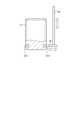
- FIG. 7 is a diagram for explaining the operation of the exchange device 66 according to the embodiment.
- the rotating body 9 includes a vehicle body frame 9A and a rear cover 9B arranged at the rear of the vehicle body frame 9A.
- the work machine 11 is connected to the front of the vehicle body frame 9A.
- the battery connector 65 is arranged inside the vehicle body frame 9A.
- the rear cover 9B is arranged so as to cover an opening provided at the rear of the vehicle body frame 9A.
- the rear cover 9B is movable rearward from the vehicle body frame 9A.
- the replacement device 66 protrudes from the rotating body 9 and replaces the battery pack 31 attached to the battery connector 65.
- the replacement device 66 protrudes rearward from the rotating body 9.
- the replacement device 66 protruding rearward from the rotating body 9, transports the battery pack 31 removed from the battery connector 65 to the outside of the rotating body 9.
- the replacement position is defined below the rotating body 9.
- the replacement device 66, protruding rearward from the rotating body 9, lowers the battery pack 31 removed from the battery connector 65 to the outside of the rotating body 9.
- the replacement device 66 lowers the battery pack 31 removed from the battery connector 65 to the ground at the work site 3.
- the replacement device 66 has a base member 67 and a transport arm 68.
- the base member 67 moves in the front-rear direction by the operation of a first actuator of the replacement device 66.
- the base member 67 moves relative to the vehicle body frame 9A.
- the replacement control unit 48E causes the base member 67 to extend rearward from the vehicle body frame 9A.
- the base member 67 is disposed outside the vehicle body frame 9A.
- the base member 67 is a plate-shaped member extending in the front-rear direction.
- the rear cover 9B is fixed to the rear of the base member 67.
- the rear cover 9B moves in the front-rear direction together with the base member 67.
- the base member 67 moves rearward from the vehicle body frame 9A
- the rear cover 9B moves rearward together with the base member 67.
- the front part of the base member 67 is fixed to the battery connector 65.
- the front part of the base member 67 is connected to the center part of the battery connector 65 in the vehicle width direction.
- the battery connector 65 moves in the front-rear direction together with the base member 67.
- the battery connector 65 moves rearward together with the base member 67.
- the first battery pack 31 is attached to and detached from the battery connector 65 to the left of the base member 67.
- the second battery pack 31 is attached to and detached from the battery connector 65 to the right of the base member 67.
- the base member 67 extends rearward from the rotating body 9 while supporting the transport arm 68.
- the base member 67 and the transport arm 68 are positioned outside the vehicle frame 9A.
- the transport arm 68 transports the battery pack 31.
- the transport arm 68 raises and lowers the battery pack 31.
- the transport arm 68 moves in the up and down direction by the operation of the second actuator of the exchange device 66.
- Two transport arms 68 raise and lower one battery pack 31.
- the two transport arms 68 are arranged at a distance in the front-rear direction.
- the exchange control unit 48E raises and lowers the transport arm 68 after extending the base member 67 from the rear of the vehicle body frame 9A. As shown in FIG. 8, the transport arm 68 lowers the battery pack 31 removed from the battery connector 65 to the outside of the rotating body 9.
- the transport arm 68 lowers the battery pack 31 removed from the battery connector 65 to the first exchange position defined in the exchange area.
- the exchange device 66 has a support arm 69 that is movably supported by the transport arm 68.
- the support arm 69 is connected to the lower end of the transport arm 68.
- the support arm 69 moves in the vehicle width direction (left and right direction) of the rotating body 9 by the operation of a third actuator that the exchange device 66 has.
- a recess 31R is provided on the outer surface of the battery pack 31.
- the recess 31R is provided on each of the left and right surfaces of the battery pack 31.
- Two recesses 31R are provided in the front-to-rear direction on the left surface of the battery pack 31.
- Two recesses 31R are provided in the front-to-rear direction on the right surface of the battery pack 31.
- the two recesses 31R are provided in the lower part of the right surface of the battery pack 31.
- the support arm 69 is inserted into and removed from the recess 31R of the battery pack 31.
- the two transport arms 68 are arranged in the front-to-rear direction, and the two recesses 31R are provided in the front-to-rear direction on the outer surface of the battery pack 31.
- the support arm 69 supported by the front transport arm 68 is inserted into and removed from the front recess 31R.
- the support arm 69 supported by the rear transport arm 68 is inserted into and removed from the rear recess 31R.
- the replacement control unit 48E lowers the transport arm 68 with the support arm 69 inserted into the recess 31R of the battery pack 31. After the battery pack 31 is lowered to the first replacement position, the replacement control unit 48E removes the support arm 69 from the recess 31R of the battery pack 31.
- the excavator 2A moves to the second replacement position at the work site 3 where the second battery pack 31 is arranged.
- the first battery pack 31 is the battery pack 31 disconnected from the battery connector 65 and has a low remaining capacity.
- the second battery pack 31 is the battery pack 31 with a high remaining capacity.
- the replacement device 66 picks up the battery pack 31 arranged at the second replacement position outside the rotating body 9 while extending rearward from the rotating body 9.
- the replacement device 66 picks up the battery pack 31 from the ground at the work site 3.
- the replacement device 66 picks up the battery pack 31 arranged at the second replacement position defined in the replacement area.
- the replacement control unit 48E may output a replacement command so that the battery pack 31 with the highest remaining capacity is attached to the battery connector 65.
- the battery data acquired by the battery data acquisition unit 48B includes the remaining capacity of each of the multiple battery packs 31 arranged in the replacement area outside the rotating body 9.
- the replacement control unit 48E can output a replacement command to pick up the battery pack 31 with the highest remaining capacity based on the battery data.
- the exchange control unit 48E When picking up the battery pack 31, the exchange control unit 48E inserts the support arm 69 into the recess 31R of the battery pack 31 while the transport arm 68 is lowered. After the support arm 69 is inserted into the recess 31R of the battery pack 31, the exchange control unit 48E raises the transport arm 68. As the transport arm 68 rises, the battery pack 31 arranged outside the rotating body 9 is picked up by the exchange device 66. The battery pack 31 picked up by the transport arm 68 is attached to the battery connector 65. After the battery pack 31 is attached to the battery connector 65, the exchange device 66 moves the base member 67 forward. As the base member 67 moves forward, the battery connector 65 and the rear cover 9B move forward together with the base member 67. As the base member 67 moves forward, the battery pack 31 attached to the battery connector 65 is positioned inside the rotating body 9.
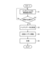
- [How to replace the battery pack] 10 is a flowchart showing a method for replacing the battery pack 31 according to the embodiment.
- the shovel 2A is remotely operated by the remote operation device 6, but the autonomous control of the on-board controller 40 is interrupted in replacing the battery pack 31, and the shovel 2A autonomously replaces the battery pack 31.
- the remaining capacity calculation unit 48A calculates the remaining capacity of the battery pack 31 attached to the battery connector 65 based on the detection data of the battery sensor 41 (step S1).
- the replacement control unit 48E acquires the remaining capacity of the battery pack 31 calculated by the remaining capacity calculation unit 48A. Based on the remaining capacity of the battery pack 31 attached to the battery connector 65, the replacement control unit 48E determines whether or not the battery pack 31 attached to the battery connector 65 needs to be replaced (step S2). In the embodiment, when the replacement control unit 48E determines that the remaining capacity of the battery pack 31 attached to the battery connector 65 is equal to or less than a predetermined threshold, it determines that the battery pack 31 attached to the battery connector 65 needs to be replaced.
- step S2 If it is determined in step S2 that the battery pack 31 does not need to be replaced (step S2: No), the process returns to step S1. If it is determined in step S2 that the battery pack 31 needs to be replaced (step S2: Yes), the battery pack 31 replacement process is started. When replacing the battery pack 31, the excavator 2A is autonomously controlled by the on-board controller 40.
- the battery data acquisition unit 48B receives battery data from the management server 8 (step S3).
- the travel control unit 48D moves the shovel 2A to the exchange area based on the battery data received in step S3 (step S4).
- the battery data includes the position of the exchange area at the work site 3.
- the travel control unit 48D controls the travel unit 10 so that the rotating unit 9 moves to the exchange area based on the position of the rotating unit 9 detected by the position sensor 42 and the position of the exchange area.
- the replacement control unit 48E starts replacing the battery pack 31 (step S5).
- the replacement control unit 48E causes the replacement device 66 to extend rearward from the vehicle body frame 9A.
- the replacement control unit 48E controls the replacement device 66 so that the replacement device 66 extending rearward from the vehicle body frame 9A lowers the battery pack 31 removed from the battery connector 65 to a first replacement position outside the rotating body 9. This causes the battery pack 31 inside the rotating body 9 to be transported to the outside of the rotating body 9.
- the travel control unit 48D controls the travelling body 10 so that the shovel 2A moves to the second exchange position where the second battery pack 31 with the most remaining capacity is stored.
- the exchange control unit 48E controls the exchange device 66 extending rearward from the vehicle frame 9A so that the exchange device 66 picks up the battery pack 31 stored at the second exchange position outside the revolving body 9.
- the battery pack 31 picked up from the second replacement position is attached to the battery connector 65.
- the replacement control unit 48E moves the replacement device 66 forward.
- the battery pack 31 attached to the battery connector 65 is positioned inside the rotating body 9.
- the battery pack 31 outside the rotating body 9 is transported into the interior of the rotating body 9.
- the excavator 2A comprises a rotating body 9, a work machine 11 connected to the front part of the rotating body 9, a battery connector 65 arranged inside the rotating body 9, and an exchange device 66 that extends from the rotating body 9 and exchanges the battery pack 31 attached to the battery connector 65.
- the replacement device 66 when replacing the battery pack 31, the replacement device 66 extends from the rotating body 9, so the battery pack 31 replacement process can be carried out smoothly.
- the battery pack 31 can be replaced without manual intervention by the replacement device 66.
- the replacement device 66 When replacing the battery pack 31, the replacement device 66 extends rearward from the rotating body 9, preventing interference between the work machine 11 connected to the front of the rotating body 9 and the replacement device 66, and between the work machine 11 and the battery pack 31. This allows the battery pack 31 to be replaced smoothly.
- the replacement device 66 while extending rearward from the rotating body 9, lowers the battery pack 31 removed from the battery connector 65 to the outside of the rotating body 9, and picks up the battery pack 31 that is located outside the rotating body 9. This allows the battery pack 31 attached to the battery connector 65 to be replaced.
- the work machine 11 is connected to the front of the rotating body 9, and the battery pack 31 is disposed at the rear of the rotating body 9.
- the battery pack 31 functions as a counterweight for the rotating body 9, stabilizing the operation of the excavator 2A.
- the replacement control unit 48E determines that the remaining capacity of the battery pack 31 attached to the battery connector 65 is equal to or less than a predetermined threshold, it outputs a replacement command to replace the battery pack 31. This allows the battery pack 31 to be replaced at an appropriate time.
- the excavator 2A autonomously moves to the replacement area. This allows the battery pack 31 to be properly replaced.
- the battery pack 31 with the greatest remaining capacity is attached to the battery connector 65. This allows the optimal battery pack 31 to be attached to the battery connector 65.
- the remaining capacity of the battery pack 31 attached to the battery connector 65 is calculated by the remaining capacity calculation unit 48A, and when the replacement control unit 48E determines that the remaining capacity calculated by the remaining capacity calculation unit 48A is equal to or less than a threshold, it outputs a replacement command to replace the battery pack 31.
- the remaining capacity calculated by the remaining capacity calculation unit 48A may be transmitted to the management server 8.
- the management server 8 may manage the remaining capacity of the battery pack 31 attached to the battery connector 65.
- the management server 8 may transmit a replacement command to the excavator 2A based on the remaining capacity of the battery pack 31 attached to the battery connector 65.
- the autonomous control of the on-board controller 40 is interrupted, and the excavator 2A autonomously replaces the battery pack 31.
- the operator may replace the battery pack 31 by operating the remote control device 6. That is, the replacement device 66 may be operated or the excavator 2A may move from the first replacement position to the second replacement position based on a remote operation command from the information terminal 5.
- the shovel 2A is remotely operated by the remote operation device 6.
- An operation device for operating the shovel 2A may be provided on the shovel 2A, and an operator on board the shovel 2A may operate the operation device to replace the battery pack 31.
- the replacement device 66 may be operated or the shovel 2A may be moved from the first replacement position to the second replacement position by the driving operation of the operator on board the shovel 2A.
- the exchange device 66 is configured to protrude to the rear of the rotating body 9.
- the exchange device 66 may protrude to the side (left or right) of the rotating body 9, may protrude above the rotating body 9, or may protrude below the rotating body 9.
- the replacement positions (first and second replacement positions) of the battery pack 31 are defined below the rotating body 9.
- the transport arm 68 of the replacement device 66 lowers the first battery pack 31 removed from inside the rotating body 9 to the first replacement position, and picks up the second battery pack 31 from the second replacement position to be brought into the rotating body 9.
- the replacement positions (first and second replacement positions) of the battery pack 31 may be defined to the side (left or right) of the rotating body 9, above the rotating body 9, or behind the rotating body 9. It is sufficient for the replacement device 66 including the transport arm 68 to be able to transport the battery pack 31 between the rotating body 9 and the replacement positions.
- the direction in which the replacement device 66 protrudes relative to the rotating body 9 may be different from or the same as the direction of the replacement position (first replacement position or second replacement position) of the battery pack 31 relative to the rotating body 9.
- the exchange device 66 has a fork capable of transporting the battery pack 31 from inside the rotating body 9 to the side or rear of the rotating body 9, so that the exchange device 66 can extend the battery pack 31 arranged inside the rotating body 9 to the rear of the rotating body 9 and then transport it to the first exchange position defined to the side or rear of the rotating body 9.
- the exchange device 66 has a fork capable of transporting the battery pack 31 from the side or rear of the rotating body 9 into the inside of the rotating body 9, so that the battery pack 31 arranged on the side or rear of the rotating body 9 can be transported into the extended exchange device 66 and then transported into the inside of the rotating body 9.
- the exchange device 66 has a crane that can transport the battery pack 31 from inside the rotating body 9 to above the rotating body 9, so that the battery pack 31 arranged inside the rotating body 9 can be extended upward and then transported to the first exchange position defined above the rotating body 9.
- the excavator 2A can be moved to the vicinity of the second exchange position, and then the exchange device 66 has a crane, so that the battery pack 31 arranged at the second exchange position can be carried into the extended exchange device 66 and then carried into the inside of the rotating body 9.
- the first exchange position may be defined in any one of the directions below, to the side, to the rear, and above the rotating body 9, and the second exchange position may be defined in a direction different from the first exchange position.
- the second exchange position may be defined in any one of the directions of the side, to the rear, and above the rotating body 9.
- the second battery pack 31 arranged at the second exchange position to the side of the rotating body 9 may be carried into the protruding exchange device 66 and then carried into the inside of the rotating body 9.
- the second battery pack 31 arranged at the second exchange position is carried into the inside of the rotating body 9 without moving the excavator 2A.
- the exchange device 66 may be provided on a bulldozer 2B.
- the exchange device 66 may be provided on an electric wheel loader.
- the work machine 2 on which the exchange device 66 is provided may not have a work implement 11.
- the exchange device 66 may be provided on a dump truck 2C.
- 1...Management system 2...Construction machine, 2A...Shovel, 2B...Bulldozer, 2C...Dump truck, 3...Work site, 4...Remote control room, 5...Information terminal, 6...Remote control device, 7...Communication system, 8...Management server, 9...Turning body, 9A...Vehicle frame, 9B...Rear cover, 10...Travel body, 10A...Crawler track, 11...Construction machine, 11A...Boom, 11B...Arm, 11C...Bucket, 12...Construction machine cylinder, 12A...Boom cylinder, 12B...Arm cylinder, 12C...Bucket cylinder, 30...Control system, 31...Battery pack, 31R...Recess, 33...D C/DC converter, 34...
- inverter 35... electric motor, 36... hydraulic pump, 37... main valve, 38... hydraulic actuator, 40... on-board controller, 41... battery sensor, 42... position sensor, 43... communication device, 48... processor, 48A... remaining capacity calculation unit, 48B... battery data acquisition unit, 48C... position data acquisition unit, 48D... driving control unit, 48E... exchange control unit, 49... main memory, 50... storage, 51... interface, 65... battery connector, 66... exchange device, 67... base member, 68... transport arm, 69... support arm.
Landscapes
- Engineering & Computer Science (AREA)
- Mining & Mineral Resources (AREA)
- Civil Engineering (AREA)
- General Engineering & Computer Science (AREA)
- Structural Engineering (AREA)
- Power Engineering (AREA)
- Transportation (AREA)
- Mechanical Engineering (AREA)
- Sustainable Development (AREA)
- Sustainable Energy (AREA)
- Life Sciences & Earth Sciences (AREA)
- Operation Control Of Excavators (AREA)
- Battery Mounting, Suspending (AREA)
Abstract
作業機械は、車体と、車体の前部に連結される作業機と、車体の内部に配置されるバッテリコネクタと、車体から張り出して、バッテリコネクタに装着されるバッテリパックを交換する交換装置と、を備える。
Description
本開示は、作業機械及びバッテリパックの交換方法に関する。
作業機械に係る技術分野において、特許文献1に開示されているような電動建設機械が知られている。
電動式の作業機械にバッテリパックが搭載される場合、バッテリパックを交換できる技術が要望される。
本開示は、作業機械のバッテリパックを交換することを目的とする。
本開示に従えば、車体と、車体の前部に連結される作業機と、車体の内部に配置されるバッテリコネクタと、車体から張り出して、バッテリコネクタに装着されるバッテリパックを交換する交換装置と、を備える、作業機械が提供される。
本開示によれば、作業機械のバッテリパックが交換される。
以下、本開示に係る実施形態について図面を参照しながら説明するが、本開示は実施形態に限定されない。以下で説明する実施形態の構成要素は適宜組み合わせることができる。また、一部の構成要素を用いない場合もある。
[管理システムの概要]
図1は、実施形態に係る作業機械2の管理システム1を示す図である。管理システム1は、作業現場3で稼動する作業機械2を管理する。実施形態において、作業機械2は、バッテリパック及び電動モータを動力源とする電動式の作業機械である。作業現場3に複数の作業機械2が存在する。図1に示す例において、作業現場3に存在する作業機械2は、ショベル2Aと、ブルドーザ2Bと、ダンプトラック2Cとを含む。
図1は、実施形態に係る作業機械2の管理システム1を示す図である。管理システム1は、作業現場3で稼動する作業機械2を管理する。実施形態において、作業機械2は、バッテリパック及び電動モータを動力源とする電動式の作業機械である。作業現場3に複数の作業機械2が存在する。図1に示す例において、作業現場3に存在する作業機械2は、ショベル2Aと、ブルドーザ2Bと、ダンプトラック2Cとを含む。
実施形態において、作業機械2に操作者は搭乗しない。作業機械2は、遠隔操作される。作業機械2の外部に遠隔操作室4が設置される。遠隔操作室4は、作業現場3の遠隔地に設置される。作業機械2を遠隔操作するための情報端末5及び遠隔操作装置6のそれぞれが遠隔操作室4に配置される。情報端末5及び遠隔操作装置6のそれぞれは、作業機械2の外部に存在する。情報端末5は、遠隔操作室4に配置されるコンピュータシステムを含む。
遠隔操作装置6は、遠隔操作室4において操作者に操作される。遠隔操作装置6は、操作者に操作されることにより、作業機械2を遠隔操作する操作信号を生成する。遠隔操作装置6において生成された操作信号は、情報端末5に入力される。情報端末5は、遠隔操作装置6からの操作信号に基づいて、遠隔操作指令を生成する。情報端末5は、通信システム7を介して遠隔操作指令を作業機械2に送信する。
作業機械2は、作業機械2の外部に存在する情報端末5から送信される遠隔操作指令に基づいて動作する。作業機械2及び作業現場3の少なくとも一方に、作業現場3の画像データを取得するカメラが設けられる。作業現場3の画像データは、通信システム7を介して情報端末5に送信され、情報端末5の表示装置に表示される。操作者は、作業現場3の画像データを確認しながら、遠隔操作装置6を操作することができる。
通信システム7は、公衆通信回線を含んでもよいし特定通信回線を含んでもよい。通信システム7として、携帯電話通信網又は衛星通信網が例示される。なお、通信システム7は、インターネット(internet)を含んでもよいし、ローカルエリアネットワーク(Local Area Network)を含んでもよい。
管理システム1は、管理サーバ8を有する。管理サーバ8は、コンピュータシステムを含む。管理サーバ8は、通信システム7を介して作業機械2と通信することができる。管理サーバ8は、作業機械2の稼働データを収集する。管理サーバ8は、作業機械2に制御指令を出力する。
[作業機械]
図2は、実施形態に係るショベル2Aを示す左前方からの図である。ショベル2Aは、旋回体9と、走行体10と、作業機11と、作業機シリンダ12とを有する。
図2は、実施形態に係るショベル2Aを示す左前方からの図である。ショベル2Aは、旋回体9と、走行体10と、作業機11と、作業機シリンダ12とを有する。
旋回体9は、ショベル2Aの車体である。走行体10は、ショベル2Aの走行装置である。走行体10は、旋回体9を支持する。旋回体9は、走行体10に旋回可能に支持される。旋回体9は、走行体10よりも上方に配置される。走行体10は、旋回体9を支持して走行する。走行体10は、一対の履帯10Aを有する。履帯10Aが回転することにより、ショベル2Aが走行する。
作業機11は、旋回体9の前部に連結される。作業機11は、旋回体9の前部に連結されるブーム11Aと、ブーム11Aに連結されるアーム11Bと、アーム11Bに連結されるバケット11Cとを含む。作業機シリンダ12は、ブーム11Aを動作させるブームシリンダ12Aと、アーム11Bを動作させるアームシリンダ12Bと、バケット11Cを動作させるバケットシリンダ12Cとを含む。
図3は、実施形態に係るショベル2Aを上方から見た図である。図3は、ショベル2Aの一部を破断した図である。ショベル2Aは、旋回体9の内部に配置されるバッテリコネクタ65を備える。バッテリコネクタ65にバッテリパック31が装着される。バッテリパック31は、ショベル2Aの電源である。バッテリパック31は、複数のセルバッテリを含む。セルバッテリは、二次電池を含む。実施形態において、セルバッテリは、リチウムイオンバッテリ(LiB:Lithium ion Battery)を含む。
バッテリパック31は、バッテリコネクタ65に着脱される。複数のバッテリパック31がバッテリコネクタ65に装着される。実施形態において、バッテリコネクタ65は、旋回体9の車幅方向(左右方向)に長い。実施形態において、2つのバッテリパック31がバッテリコネクタ65に装着される。2つのバッテリパック31は、車幅方向に配置される。なお、バッテリコネクタ65に装着されるバッテリパック31は、1つでもよいし、3つ以上の任意の複数でもよい。
ショベル2Aは、バッテリコネクタ65に装着されるバッテリパック31を交換する交換装置66を備える。交換装置66は、旋回体9から張り出して、バッテリコネクタ65に装着されるバッテリパック31を交換する。
[制御システム]
図4は、実施形態に係るショベル2Aの制御システム30を示す図である。ショベル2Aは、制御システム30を有する。制御システム30は、バッテリパック31と、バッテリコネクタ65と、交換装置66と、DC/DCコンバータ33と、インバータ34と、電動モータ35と、油圧ポンプ36と、メインバルブ37と、油圧アクチュエータ38と、車載コントローラ40と、バッテリセンサ41と、位置センサ42と、通信機43とを有する。
図4は、実施形態に係るショベル2Aの制御システム30を示す図である。ショベル2Aは、制御システム30を有する。制御システム30は、バッテリパック31と、バッテリコネクタ65と、交換装置66と、DC/DCコンバータ33と、インバータ34と、電動モータ35と、油圧ポンプ36と、メインバルブ37と、油圧アクチュエータ38と、車載コントローラ40と、バッテリセンサ41と、位置センサ42と、通信機43とを有する。
バッテリパック31は、バッテリコネクタ65に着脱される。バッテリパック31は、給電端子を有する。バッテリコネクタ65は、受電端子を有する。バッテリパック31がバッテリコネクタ65に装着され、バッテリパック31の給電端子とバッテリコネクタ65の受電端子とが接続されることにより、バッテリパック31からバッテリコネクタ65に電力が供給される。
交換装置66は、バッテリコネクタ65に装着されるバッテリパック31を交換する。交換装置66は、バッテリコネクタ65からバッテリパック31を外すことができる。交換装置66は、バッテリコネクタ65から外されたバッテリパック31を旋回体9の外部に搬出することができる。交換装置66は、バッテリパック31をバッテリコネクタ65に装着することができる。交換装置66は、バッテリコネクタ65に装着されたバッテリパック31を旋回体9の内部に搬入することができる。
DC/DCコンバータ33は、バッテリパック31からの電圧を昇圧する。DC/DCコンバータ33は、バッテリパック31からの直流電流をインバータ34に供給する。
インバータ34は、DC/DCコンバータ33からの直流電流を三相交流電流に変換して電動モータ35に供給する。電動モータ35は、インバータ34から供給された三相交流電流に基づいて駆動される。
電動モータ35は、ショベル2Aの動力源である。電動モータ35は、バッテリパック31からの電力に基づいて駆動する。
油圧ポンプ36は、電動モータ35により駆動される。油圧ポンプ36は、作動油を吐出する。油圧ポンプ36から吐出された作動油は、メインバルブ37を介して、油圧アクチュエータ38に供給される。ショベル2Aの油圧アクチュエータ38は、作業機シリンダ12を含む。
なお、油圧アクチュエータ38の代わりに電動アクチュエータがショベル2Aに設けられてもよい。作業機シリンダ12が電動シリンダでもよい。油圧アクチュエータ38の代わりに電動アクチュエータがショベル2Aに設けられる場合、油圧ポンプ36及びメインバルブ37は省略される。
車載コントローラ40は、コンピュータシステムを含む。車載コントローラ40は、少なくとも交換装置66を制御する。
バッテリセンサ41は、バッテリパック31の電圧を検出する電圧センサを含む。位置センサ42は、ショベル2Aの位置を検出する。ショベル2Aの位置は、全地球航法衛星システム(GNSS:Global Navigation Satellite System)を利用して検出される。全地球航法衛星システムは、全地球測位システム(GPS:Global Positioning System)を含む。全地球航法衛星システムは、緯度、経度、及び高度の座標データで規定されるグローバル座標系の位置を検出する。グローバル座標系とは、地球に固定された座標系をいう。位置センサ42は、旋回体9に配置されたGNSS受信機を含む。位置センサ42は、グローバル座標系における旋回体9の位置を検出する。通信機43は、管理サーバ8と無線通信する。
[車載コントローラ]
図5は、実施形態に係る車載コントローラ40を示すブロック図である。管理サーバ8及び車載コントローラ40のそれぞれは、コンピュータシステムを含む。車載コントローラ40は、CPU(Central Processing Unit)のようなプロセッサ48と、ROM(Read Only Memory)のような不揮発性メモリ及びRAM(Random Access Memory)のような揮発性メモリを含むメインメモリ49と、ストレージ50と、入出力回路を含むインターフェース51とを有する。車載コントローラ40の機能は、コンピュータプログラムとしてストレージ50に記憶されている。プロセッサ48は、コンピュータプログラムをストレージ50から読み出してメインメモリ49に展開し、コンピュータプログラムに従って処理を実行する。なお、コンピュータプログラムは、ネットワークを介して管理サーバ8に配信されてもよい。
図5は、実施形態に係る車載コントローラ40を示すブロック図である。管理サーバ8及び車載コントローラ40のそれぞれは、コンピュータシステムを含む。車載コントローラ40は、CPU(Central Processing Unit)のようなプロセッサ48と、ROM(Read Only Memory)のような不揮発性メモリ及びRAM(Random Access Memory)のような揮発性メモリを含むメインメモリ49と、ストレージ50と、入出力回路を含むインターフェース51とを有する。車載コントローラ40の機能は、コンピュータプログラムとしてストレージ50に記憶されている。プロセッサ48は、コンピュータプログラムをストレージ50から読み出してメインメモリ49に展開し、コンピュータプログラムに従って処理を実行する。なお、コンピュータプログラムは、ネットワークを介して管理サーバ8に配信されてもよい。
同様に、管理サーバ8は、プロセッサと、メインメモリと、ストレージと、インターフェースとを有する。
プロセッサ48は、残容量算出部48Aと、バッテリデータ取得部48Bと、位置データ取得部48Cと、走行制御部48Dと、交換制御部48Eとを有する。
残容量算出部48Aは、バッテリセンサ41の検出データに基づいて、バッテリコネクタ65に装着されているバッテリパック31の残容量を算出する。バッテリパック31の残容量は、バッテリパック31の充電率(SOC:State Of Charge)とみなされてもよい。バッテリパック31の充電率とは、満充電容量に対する残容量の比率をいう。バッテリセンサ41は、バッテリコネクタ65に装着されているバッテリパック31の電圧を検出する。残容量算出部48Aは、バッテリセンサ41の検出データに基づいて、バッテリコネクタ65に装着されているバッテリパック31の残容量を算出することができる。
旋回体9の外部に配置されているバッテリパック31に係るバッテリデータが管理サーバ8に記憶されている。バッテリデータは、旋回体9の外部に配置されているバッテリパック31の位置、及び旋回体9の外部に配置されているバッテリパック31の残容量を含む。バッテリデータ取得部48Bは、バッテリデータを、通信システム7を介して管理サーバ8から受信する。
なお、バッテリデータは、バッテリパック31に保持されていてもよい。バッテリデータ取得部48Bは、バッテリパック31と直接的に無線通信して、バッテリパック31からバッテリデータを取得してもよい。
位置データ取得部48Cは、位置センサ42の検出データを取得する。位置センサ42の検出データは、旋回体9の位置を示す。
走行制御部48Dは、ショベル2Aの走行を制御する。走行制御部48Dは、走行体10を制御する走行指令を出力する。
交換制御部48Eは、交換装置66を制御する。交換制御部48Eは、バッテリコネクタ65に装着されるバッテリパック31を交換する交換指令を出力する。
[バッテリパックの交換]
実施形態においては、作業現場3において、バッテリコネクタ65に装着されるバッテリパック31が交換される。バッテリコネクタ65に装着されているバッテリパック31の残容量が少ない場合、バッテリコネクタ65に装着されるバッテリパック31は、旋回体9の外部に配置されている残容量が多いバッテリパック31と交換される。
実施形態においては、作業現場3において、バッテリコネクタ65に装着されるバッテリパック31が交換される。バッテリコネクタ65に装着されているバッテリパック31の残容量が少ない場合、バッテリコネクタ65に装着されるバッテリパック31は、旋回体9の外部に配置されている残容量が多いバッテリパック31と交換される。
図6は、実施形態に係るバッテリパック31の交換動作を説明するための図である。作業現場3の交換エリアに残容量が多いバッテリパック31が保管される。交換エリアは、予め規定されており、管理サーバ8に記憶される。交換エリアは、バッテリパック31の交換位置を含む。
交換位置は、旋回体9よりも下方に規定される。実施形態において、交換位置は、走行体10が走行する作業現場3の地面の所定の位置である。作業現場3の地面に残容量が多いバッテリパック31が保管される。交換エリアには、1つのバッテリパック31が保管されてもよいし、複数のバッテリパック31が保管されてもよい。作業現場3の複数の交換エリアが規定されてもよい。相互に異なる複数の交換エリアのそれぞれにバッテリパック31が保管されてもよい。
残容量算出部48Aは、バッテリセンサ41の検出データに基づいて、バッテリコネクタ65に装着されているバッテリパック31の残容量を算出する。交換制御部48Eは、残容量算出部48Aにより算出されたバッテリパック31の残容量を取得する。交換制御部48Eは、バッテリコネクタ65に装着されているバッテリパック31の残容量が予め定められている閾値以下であるか否かを判定する。バッテリコネクタ65に装着されているバッテリパック31の残容量が閾値以下であると判定した場合、交換制御部48Eは、バッテリコネクタ65からバッテリパック31が外され、旋回体9の外部の交換エリアに配置されているバッテリパック31がバッテリコネクタ65に装着されるように、交換指令を出力する。
交換指令が出力された場合、走行制御部48Dは、ショベル2Aが交換エリアに移動するように、走行体10を制御する走行指令を出力する。位置データ取得部48Cは、位置センサ42から旋回体9の位置を取得する。バッテリデータ取得部48Bは、管理サーバ8からバッテリデータを取得する。バッテリデータは、旋回体9の外部に配置されているバッテリパック31の位置を含む。すなわち、バッテリデータは、交換エリアの位置を含む。走行制御部48Dは、旋回体9の位置と、旋回体9の外部のバッテリパック31の位置である交換エリアの位置とに基づいて、旋回体9が交換エリアに移動するように、走行体10を制御する走行指令を出力する。走行制御部48Dは、旋回体9が交換エリアに移動するように、作業現場3において走行体10を走行させる。
なお、作業現場3に複数の交換エリアが規定されている場合、走行制御部48Dは、ショベル2Aの現在の位置から最も近い交換エリアに旋回体9を移動してもよい。作業現場3に複数の交換エリアが規定されている場合、走行制御部48Dは、残容量が最も多いバッテリパック31が保管されている交換エリアに旋回体9を移動してもよい。バッテリデータ取得部48Bが取得するバッテリデータは、旋回体9の外部に配置されているバッテリパック31の複数の交換エリアの位置、及び旋回体9の外部の複数の交換エリアのそれぞれに保管されているバッテリパック31の残容量を含む。走行制御部48Dは、バッテリデータに基づいて、ショベル2Aの現在の位置から最も近い交換エリアに旋回体9を移動することができる。走行制御部48Dは、バッテリデータに基づいて、残容量が最も多いバッテリパック31が保管されている交換エリアに旋回体9を移動することができる。
図7、図8、及び図9のそれぞれは、実施形態に係る交換装置66の動作を説明するための図である。図7に示すように、旋回体9は、車体フレーム9Aと、車体フレーム9Aの後部に配置されるリヤカバー9Bとを含む。車体フレーム9Aの前部に作業機11が連結される。バッテリコネクタ65は、車体フレーム9Aの内部に配置される。リヤカバー9Bは、車体フレーム9Aの後部に設けられている開口を覆うように配置される。リヤカバー9Bは、車体フレーム9Aから後方に移動可能である。
交換装置66は、旋回体9から張り出して、バッテリコネクタ65に装着されるバッテリパック31を交換する。実施形態において、交換装置66は、旋回体9から後方に張り出す。図8に示すように、交換装置66は、旋回体9から後方に張り出した状態で、バッテリコネクタ65から外されたバッテリパック31を旋回体9の外部に搬出する。上述のように、実施形態において、交換位置は、旋回体9よりも下方に規定される。交換装置66は、旋回体9から後方に張り出した状態で、バッテリコネクタ65から外されたバッテリパック31を旋回体9の外部に降ろす。交換装置66は、バッテリコネクタ65から外されたバッテリパック31を作業現場3の地面に降ろす。
交換装置66は、ベース部材67と、搬送アーム68とを有する。ベース部材67は、交換装置66が有する第1アクチュエータの作動により、前後方向に移動する。ベース部材67は、車体フレーム9Aと相対移動する。バッテリパック31の交換において、交換制御部48Eは、ベース部材67を車体フレーム9Aから後方に張り出す。バッテリパック31の交換において、ベース部材67は、車体フレーム9Aの外側に配置される。実施形態において、ベース部材67は、前後方向に延びるプレート状の部材である。リヤカバー9Bは、ベース部材67の後部に固定される。リヤカバー9Bは、ベース部材67と一緒に前後方向に移動する。ベース部材67が車体フレーム9Aよりも後方に移動した場合、リヤカバー9Bは、ベース部材67と一緒に後方に移動する。
ベース部材67の前部は、バッテリコネクタ65に固定される。ベース部材67の前部は、バッテリコネクタ65の車幅方向の中央部に接続される。実施形態において、バッテリコネクタ65は、ベース部材67と一緒に前後方向に移動する。ベース部材67が車体フレーム9Aよりも後方に移動した場合、バッテリコネクタ65は、ベース部材67と一緒に後方に移動する。第1のバッテリパック31は、ベース部材67よりも左方においてバッテリコネクタ65に着脱される。第2のバッテリパック31は、ベース部材67よりも右方においてバッテリコネクタ65に着脱される。
ベース部材67は、搬送アーム68を支持した状態で、旋回体9から後方に張り出す。バッテリパック31の交換において、ベース部材67及び搬送アーム68は、車体フレーム9Aの外側に配置される。
搬送アーム68は、バッテリパック31を搬送する。実施形態において、搬送アーム68は、バッテリパック31を昇降する。搬送アーム68は、交換装置66が有する第2アクチュエータの作動により、上下方向に移動する。2つの搬送アーム68が1つのバッテリパック31を昇降する。2つの搬送アーム68は、前後方向に間隔をあけて配置される。交換制御部48Eは、ベース部材67を車体フレーム9Aから後方から張り出した後、搬送アーム68を昇降させる。図8に示すように、搬送アーム68は、バッテリコネクタ65から外されたバッテリパック31を旋回体9の外部に降ろす。搬送アーム68は、バッテリコネクタ65から外されたバッテリパック31を交換エリアに規定された第1の交換位置に降ろす。
図9に示すように、交換装置66は、搬送アーム68に移動可能に支持される支持アーム69を有する。支持アーム69は、搬送アーム68の下端部に接続される。支持アーム69は、交換装置66が有する第3アクチュエータの作動により、旋回体9の車幅方向(左右方向)に移動する。
バッテリパック31の外面に凹部31Rが設けられる。凹部31Rは、バッテリパック31の左面及び右面のそれぞれに設けられる。バッテリパック31の左面において、凹部31Rは、前後方向に2つ設けられる。バッテリパック31の右面において、凹部31Rは、前後方向に2つ設けられる。2つの凹部31Rは、バッテリパック31の右面の下部に設けられる。
支持アーム69は、バッテリパック31の凹部31Rに挿抜される。上述のように、2つの搬送アーム68が前後方向に配置され、2つの凹部31Rがバッテリパック31の外面において前後方向に設けられる。前側の搬送アーム68に支持されている支持アーム69が前側の凹部31Rに挿抜される。後側の搬送アーム68に支持されている支持アーム69が後側の凹部31Rに挿抜される。
バッテリパック31を作業現場3の地面に規定された第1の交換位置に降ろす場合、交換制御部48Eは、支持アーム69がバッテリパック31の凹部31Rに挿入された状態で、搬送アーム68を下降させる。バッテリパック31が第1の交換位置に降ろされた後、交換制御部48Eは、支持アーム69をバッテリパック31の凹部31Rから抜去する。
バッテリコネクタ65から外された第1のバッテリパック31が旋回体9の外部の第1の交換位置に降ろされた後、第2のバッテリパック31が配置されている作業現場3の第2の交換位置にショベル2Aが移動する。第1のバッテリパック31は、バッテリコネクタ65から外された残容量が少ないバッテリパック31である。第2のバッテリパック31は、残容量が多いバッテリパック31である。交換装置66は、旋回体9から後方に張り出した状態で、旋回体9の外部の第2の交換位置に配置されているバッテリパック31を拾い上げる。交換装置66は、作業現場3の地面からバッテリパック31を拾い上げる。交換装置66は、交換エリアに規定された第2の交換位置に配置されているバッテリパック31を拾い上げる。
なお、1つの交換エリアに複数のバッテリパック31が保管されている場合、交換制御部48Eは、残容量が最も多いバッテリパック31がバッテリコネクタ65に装着されるように、交換指令を出力してもよい。バッテリデータ取得部48Bが取得するバッテリデータは、旋回体9の外部の交換エリアに配置されている複数のバッテリパック31のそれぞれの残容量を含む。交換制御部48Eは、バッテリデータに基づいて、残容量が最も多いバッテリパック31を拾い上げるように、交換指令を出力することができる。
バッテリパック31を拾い上げる場合、交換制御部48Eは、搬送アーム68を下降した状態で、支持アーム69をバッテリパック31の凹部31Rに挿入する。支持アーム69がバッテリパック31の凹部31Rに挿入された後、交換制御部48Eは、搬送アーム68を上昇させる。搬送アーム68が上昇することにより、旋回体9の外部に配置されているバッテリパック31が交換装置66に拾い上げられる。搬送アーム68により拾い上げられたバッテリパック31は、バッテリコネクタ65に装着される。バッテリパック31がバッテリコネクタ65に装着された後、交換装置66は、ベース部材67を前方に移動する。ベース部材67が前方に移動することにより、バッテリコネクタ65及びリヤカバー9Bは、ベース部材67と一緒に前方に移動する。ベース部材67が前方に移動することにより、バッテリコネクタ65に装着されたバッテリパック31が旋回体9の内部に配置される。
[バッテリパックの交換方法]
図10は、実施形態に係るバッテリパック31の交換方法を示すフローチャートである。なお、実施形態において、ショベル2Aは、遠隔操作装置6により遠隔操作されるものの、バッテリパック31の交換においては車載コントローラ40の自律制御が割り込まれ、ショベル2Aは、バッテリパック31を自律的に交換する。
図10は、実施形態に係るバッテリパック31の交換方法を示すフローチャートである。なお、実施形態において、ショベル2Aは、遠隔操作装置6により遠隔操作されるものの、バッテリパック31の交換においては車載コントローラ40の自律制御が割り込まれ、ショベル2Aは、バッテリパック31を自律的に交換する。
残容量算出部48Aは、バッテリセンサ41の検出データに基づいて、バッテリコネクタ65に装着されているバッテリパック31の残容量を算出する(ステップS1)。
交換制御部48Eは、残容量算出部48Aにより算出されたバッテリパック31の残容量を取得する。交換制御部48Eは、バッテリコネクタ65に装着されているバッテリパック31の残容量に基づいて、バッテリコネクタ65に装着されるバッテリパック31の交換が必要か否かを判定する(ステップS2)。実施形態において、交換制御部48Eは、バッテリコネクタ65に装着されているバッテリパック31の残容量が予め定められている閾値以下であると判定した場合、バッテリコネクタ65に装着されるバッテリパック31の交換が必要であると判定する。
ステップS2において、バッテリパック31の交換が必要ではないと判定された場合(ステップS2:No)、ステップS1の処理に戻る。ステップS2において、バッテリパック31の交換が必要であると判定された場合(ステップS2:Yes)、バッテリパック31の交換処理が開始される。バッテリパック31の交換において、ショベル2Aは、車載コントローラ40により自律制御される。
バッテリデータ取得部48Bは、管理サーバ8からバッテリデータを受信する(ステップS3)。
走行制御部48Dは、ステップS3において受信されたバッテリデータに基づいて、ショベル2Aを交換エリアに移動させる(ステップS4)。
バッテリデータは、作業現場3の交換エリアの位置を含む。走行制御部48Dは、位置センサ42により検出された旋回体9の位置と交換エリアの位置とに基づいて、旋回体9が交換エリアに移動するように、走行体10を制御する。
ショベル2Aが交換エリアに到着した後、交換制御部48Eは、バッテリパック31の交換を開始する(ステップS5)。
交換制御部48Eは、交換装置66を車体フレーム9Aから後方に張り出す。交換制御部48Eは、車体フレーム9Aから後方に張り出した交換装置66がバッテリコネクタ65から外されたバッテリパック31を旋回体9の外部の第1の交換位置に降ろすように、交換装置66を制御する。これにより、旋回体9の内部のバッテリパック31が旋回体9の外部に搬出される。
バッテリコネクタ65から外された第1のバッテリパック31が第1の交換位置に降ろされた後、走行制御部48Dは、残容量が多い第2のバッテリパック31が保管されている第2の交換位置にショベル2Aが移動するように、走行体10を制御する。ショベル2Aが第2の交換位置に移動した後、交換制御部48Eは、車体フレーム9Aから後方に張り出した交換装置66が旋回体9の外部の第2の交換位置に保管されているバッテリパック31を拾い上げるように、交換装置66を制御する。
第2の交換位置から拾い上げられたバッテリパック31は、バッテリコネクタ65に装着される。バッテリパック31がバッテリコネクタ65に装着された後、交換制御部48Eは、交換装置66を前方に移動させる。交換装置66が前方に移動することにより、バッテリコネクタ65に装着されたバッテリパック31が旋回体9の内部に配置される。これにより、旋回体9の外部のバッテリパック31が旋回体9の内部に搬入される。
[効果]
以上説明したように、実施形態によれば、ショベル2Aは、旋回体9と、旋回体9の前部に連結される作業機11と、旋回体9の内部に配置されるバッテリコネクタ65と、旋回体9から張り出して、バッテリコネクタ65に装着されるバッテリパック31を交換する交換装置66と、を備える。
以上説明したように、実施形態によれば、ショベル2Aは、旋回体9と、旋回体9の前部に連結される作業機11と、旋回体9の内部に配置されるバッテリコネクタ65と、旋回体9から張り出して、バッテリコネクタ65に装着されるバッテリパック31を交換する交換装置66と、を備える。
実施形態によれば、バッテリパック31の交換において、交換装置66が旋回体9からに張り出すので、バッテリパック31の交換処理が円滑に実施される。交換装置66により、人手を介さずにバッテリパック31が交換される。
バッテリパック31の交換において、交換装置66が旋回体9から後方に張り出すので、旋回体9の前部に連結されている作業機11と交換装置66とが干渉したり、作業機11とバッテリパック31とが干渉したりすることが抑制される。そのため、バッテリパック31の交換処理が円滑に実施される。
交換装置66は、旋回体9から後方に張り出した状態で、バッテリコネクタ65から外されたバッテリパック31を旋回体9の外部に降ろし、旋回体9の外部に配置されているバッテリパック31を拾い上げる。これにより、バッテリコネクタ65に装着されるバッテリパック31が交換される。
実施形態において、作業機11は、旋回体9の前部に連結され、バッテリパック31は、旋回体9の後部に配置される。バッテリパック31が旋回体9のカウンタウエイトとして機能するので、ショベル2Aの作業が安定する。
交換制御部48Eは、バッテリコネクタ65に装着されているバッテリパック31の残容量が予め定められている閾値以下であると判定した場合、バッテリパック31を交換する交換指令を出力する。これにより、適切なタイミングでバッテリパック31が交換される。
バッテリパック31を交換する場合、ショベル2Aは、交換エリアに自律的に移動する。これにより、バッテリパック31が適正に交換される。
旋回体9の外部に複数のバッテリパック31が保管されている場合、残容量が最も多いバッテリパック31がバッテリコネクタ65に装着される。これにより、最適なバッテリパック31がバッテリコネクタ65に装着される。
[その他の実施形態]
上述の実施形態において、バッテリコネクタ65に装着されているバッテリパック31の残容量が残容量算出部48Aにより算出され、交換制御部48Eは、残容量算出部48Aにより算出された残容量が閾値以下であると判定した場合、バッテリパック31を交換する交換指令を出力することとした。残容量算出部48Aにより算出された残容量が管理サーバ8に送信されてもよい。管理サーバ8が、バッテリコネクタ65に装着されているバッテリパック31の残容量を管理してもよい。管理サーバ8が、バッテリコネクタ65に装着されているバッテリパック31の残容量に基づいて、ショベル2Aに交換指令を送信してもよい。
上述の実施形態において、バッテリコネクタ65に装着されているバッテリパック31の残容量が残容量算出部48Aにより算出され、交換制御部48Eは、残容量算出部48Aにより算出された残容量が閾値以下であると判定した場合、バッテリパック31を交換する交換指令を出力することとした。残容量算出部48Aにより算出された残容量が管理サーバ8に送信されてもよい。管理サーバ8が、バッテリコネクタ65に装着されているバッテリパック31の残容量を管理してもよい。管理サーバ8が、バッテリコネクタ65に装着されているバッテリパック31の残容量に基づいて、ショベル2Aに交換指令を送信してもよい。
上述の実施形態において、バッテリパック31の交換においては車載コントローラ40の自律制御が割り込まれ、ショベル2Aは、バッテリパック31を自律的に交換することとした。操作者が遠隔操作装置6を操作してバッテリパック31を交換してもよい。すなわち、情報端末5からの遠隔操作指令に基づいて、交換装置66が作動したり、ショベル2Aが第1の交換位置から第2の交換位置に移動したりしてもよい。
上述の実施形態において、ショベル2Aは、遠隔操作装置6により遠隔操作されることとした。ショベル2Aを操作する操作装置がショベル2Aに設けられ、ショベル2Aに搭乗した操作者が操作装置を操作して、バッテリパック31を交換してもよい。すなわち、ショベル2Aに搭乗した操作者の運転操作により、交換装置66が作動したり、ショベル2Aが第1の交換位置から第2の交換位置に移動したりしてもよい。
上述の実施形態において、交換装置66は、旋回体9の後方に張り出すこととした。交換装置66は、旋回体9の側方(左方又は右方)に張り出してもよいし、旋回体9の上方に張り出してもよいし、旋回体9の下方に張り出してもよい。
上述の実施形態において、バッテリパック31の交換位置(第1の交換位置及び第2の交換位置)は、旋回体9よりも下方に規定されることとした。また、交換装置66の搬送アーム68は、旋回体9の内部から搬出された第1のバッテリパック31を第1の交換位置に降ろしたり、旋回体9の内部に搬入するための第2のバッテリパック31を第2の交換位置から拾い上げたりすることとした。バッテリパック31の交換位置(第1の交換位置及び第2の交換位置)は、旋回体9の側方(左方又は右方)に規定されてもよいし、旋回体9の上方に規定されてもよいし、旋回体9の後方に規定されてもよい。搬送アーム68を含む交換装置66は、旋回体9と交換位置との間でバッテリパック31を搬送できればよい。交換装置66が旋回体9に対して張り出す方向は、旋回体9に対するバッテリパック31の交換位置(第1の交換位置又は第2の交換位置)の方向と、異なっていてもよいし、同一でもよい。
例えば、第1の交換位置が旋回体9の側方又は後方に規定される場合、交換装置66がバッテリパック31を旋回体9の内部から旋回体9の側方又は後方に搬出可能なフォークを有することにより、交換装置66が旋回体9の内部に配置されているバッテリパック31を旋回体9の後方に張り出した後に旋回体9の側方又は後方に規定された第1の交換位置に搬出することができる。また、第2の交換位置が旋回体9の側方又は後方に規定される場合、交換装置66がバッテリパック31を旋回体9の側方又は後方から旋回体9の内部に搬入可能なフォークを有することにより、旋回体9の側方又は後方に配置されているバッテリパック31を張り出された交換装置66に運び入れた後に旋回体9の内部に搬入することができる。
例えば、第1の交換位置が旋回体9の上方に規定される場合、交換装置66がバッテリパック31を旋回体9の内部から旋回体9の上方に搬出可能なクレーンを有することにより、旋回体9の内部に配置されているバッテリパック31を上方に張り出した後に、旋回体9の上方に規定された第1の交換位置に搬出することができる。また、第2の交換位置が同じく旋回体9の上方に規定される場合、ショベル2Aを第2の交換位置の近傍まで移動させた後に、交換装置66がクレーンを有することにより、第2の交換位置に配置されたバッテリパック31を張り出された交換装置66に運び入れ、旋回体9の内部に搬入することができる。
また、第1の交換位置が旋回体9の下方、側方、後方、及び上方のいずれか一つの方向に規定され、第2の交換位置が第1の交換位置とは異なる方向に規定されてもよい。例えば、第1の交換位置が旋回体9の下方に規定された場合、第2の交換位置が旋回体9の側方、後方、及び上方のいずれか一つの方向に規定されてもよい。例えば、第1のバッテリパック31が旋回体9の内部から後方に張り出した後に旋回体9の下方の第1の交換位置に搬出された後、旋回体9の側方の第2の交換位置に配置されている第2のバッテリパック31が、張り出された交換装置66に運び入れられ、その後旋回体9の内部に搬入されてもよい。この場合、第1のバッテリパック31が旋回体9の外部の第1の交換位置に搬出された後、ショベル2Aを移動させることなく、第2の交換位置に配置されている第2のバッテリパック31が旋回体9の内部に搬入される。
上述の実施形態において、交換装置66は、ブルドーザ2Bに設けられてもよい。交換装置66は、電動式のホイールローダに設けられてもよい。交換装置66が設けられる作業機械2は、作業機11を有しなくてもよい。交換装置66は、ダンプトラック2Cに設けられてもよい。
1…管理システム、2…作業機械、2A…ショベル、2B…ブルドーザ、2C…ダンプトラック、3…作業現場、4…遠隔操作室、5…情報端末、6…遠隔操作装置、7…通信システム、8…管理サーバ、9…旋回体、9A…車体フレーム、9B…リヤカバー、10…走行体、10A…履帯、11…作業機、11A…ブーム、11B…アーム、11C…バケット、12…作業機シリンダ、12A…ブームシリンダ、12B…アームシリンダ、12C…バケットシリンダ、30…制御システム、31…バッテリパック、31R…凹部、33…DC/DCコンバータ、34…インバータ、35…電動モータ、36…油圧ポンプ、37…メインバルブ、38…油圧アクチュエータ、40…車載コントローラ、41…バッテリセンサ、42…位置センサ、43…通信機、48…プロセッサ、48A…残容量算出部、48B…バッテリデータ取得部、48C…位置データ取得部、48D…走行制御部、48E…交換制御部、49…メインメモリ、50…ストレージ、51…インターフェース、65…バッテリコネクタ、66…交換装置、67…ベース部材、68…搬送アーム、69…支持アーム。
Claims (20)
- 車体と、
前記車体の前部に連結される作業機と、
前記車体の内部に配置されるバッテリコネクタと、
前記車体から張り出して、前記バッテリコネクタに装着されるバッテリパックを交換する交換装置と、を備える、
作業機械。 - 前記交換装置は、前記車体から後方に張り出す、
請求項1に記載の作業機械。 - 前記交換装置は、前記車体から張り出した状態で、前記車体の外部に配置されているバッテリパックを前記車体の内部に搬入する、
請求項1に記載の作業機械。 - 前記交換装置は、前記車体から張り出した状態で、前記バッテリコネクタから外された前記バッテリパックを前記車体の外部に搬出する、
請求項1に記載の作業機械。 - 前記交換装置は、前記バッテリパックを搬送する搬送アームを有する、
請求項1に記載の作業機械。 - 前記搬送アームは、前記車体の外部に配置されているバッテリパックを前記車体の内部に搬入する、
請求項5に記載の作業機械。 - 前記搬送アームは、前記車体の外部に配置されているバッテリパックを拾い上げる、
請求項6に記載の作業機械。 - 前記搬送アームは、前記バッテリコネクタから外されたバッテリパックを前記車体の外部に搬出する、
請求項7に記載の作業機械。 - 前記搬送アームは、前記バッテリパックを前記車体の外部に降ろす、
請求項8に記載の作業機械。 - 前記交換装置は、前記搬送アームに移動可能に支持され、前記バッテリパックの外面に設けられた凹部に挿抜される支持アームを有する、
請求項5に記載の作業機械。 - 前記交換装置は、前記搬送アームを支持した状態で、前記車体から張り出すベース部材を有する、
請求項5に記載の作業機械。 - 前記ベース部材が前記車体から張り出した後、前記搬送アームが移動する、
請求項11に記載の作業機械。 - 前記車体は、前記作業機が連結される車体フレームと、前記車体フレームの後部に配置されるリヤカバーと、を含み、
前記リヤカバーは、前記ベース部材の後部に固定される、
請求項12に記載の作業機械。 - プロセッサを備え、
前記プロセッサは、
前記バッテリコネクタに装着されているバッテリパックの残容量を取得し、
前記バッテリパックの残容量が閾値以下であると判定した場合、前記バッテリコネクタから前記バッテリパックが外され、前記車体の外部に配置されているバッテリパックが前記バッテリコネクタに装着されるように、前記交換装置を制御する交換指令を出力する、
請求項1に記載の作業機械。 - 前記車体を支持する走行装置と、
前記車体の位置を検出する位置センサと、を備え、
前記プロセッサは、
前記車体の位置を取得し、
前記車体の外部に配置されている前記バッテリパックの位置を取得し、
前記車体の位置と前記バッテリパックの位置とに基づいて、前記車体が前記バッテリパックの位置に移動するように、前記走行装置を制御する走行指令を出力する、
請求項14に記載の作業機械。 - 前記プロセッサは、
前記車体の外部に配置されている複数のバッテリパックのそれぞれの残容量を取得し、
残容量が最も多いバッテリパックが前記バッテリコネクタに装着されるように、前記交換指令を出力する、
請求項14に記載の作業機械。 - 車体及び前記車体の前部に連結される作業機を備える作業機械において前記車体の内部に配置されているバッテリパックの交換装置を前記車体から張り出すことと、
前記車体の内部に配置されている第1のバッテリパックを前記交換装置で前記車体の外部に搬出することと、
前記車体の外部に配置されている第2のバッテリパックを前記交換装置で前記車体の内部に搬入することと、を含む、
バッテリパックの交換方法。 - 第1のバッテリパックを前記車体の外部の第1の交換位置に搬出した後、第2のバッテリパックが配置されている第2の交換位置に前記作業機械が移動する、
請求項17に記載のバッテリパックの交換方法。 - 第1のバッテリパックを前記車体の外部の第1の交換位置に搬出した後、第1の交換位置とは異なる第2の交換位置に配置されている第2のバッテリパックを前記車体の内部に搬入する、
請求項17に記載のバッテリパックの交換方法。 - 第1のバッテリパックを前記車体の外部の第1の交換位置に搬出した後、前記作業機械が移動することなく、第1の交換位置とは異なる第2の交換位置に配置されている第2のバッテリパックを前記車体の内部に搬入する、
請求項17に記載のバッテリパックの交換方法。
Priority Applications (2)
| Application Number | Priority Date | Filing Date | Title |
|---|---|---|---|
| DE112024001014.8T DE112024001014T5 (de) | 2023-05-08 | 2024-03-29 | Arbeitsmaschine und verfahren zum austauschen eines batteriepacks |
| CN202480027484.0A CN121002259A (zh) | 2023-05-08 | 2024-03-29 | 作业机械以及电池组的更换方法 |
Applications Claiming Priority (2)
| Application Number | Priority Date | Filing Date | Title |
|---|---|---|---|
| JP2023-076746 | 2023-05-08 | ||
| JP2023076746A JP2024161757A (ja) | 2023-05-08 | 2023-05-08 | 作業機械及びバッテリパックの交換方法 |
Publications (1)
| Publication Number | Publication Date |
|---|---|
| WO2024232191A1 true WO2024232191A1 (ja) | 2024-11-14 |
Family
ID=93429943
Family Applications (1)
| Application Number | Title | Priority Date | Filing Date |
|---|---|---|---|
| PCT/JP2024/013320 Ceased WO2024232191A1 (ja) | 2023-05-08 | 2024-03-29 | 作業機械及びバッテリパックの交換方法 |
Country Status (4)
| Country | Link |
|---|---|
| JP (1) | JP2024161757A (ja) |
| CN (1) | CN121002259A (ja) |
| DE (1) | DE112024001014T5 (ja) |
| WO (1) | WO2024232191A1 (ja) |
Citations (5)
| Publication number | Priority date | Publication date | Assignee | Title |
|---|---|---|---|---|
| JPS5027103Y1 (ja) * | 1970-08-07 | 1975-08-12 | ||
| JPH0995974A (ja) * | 1995-10-02 | 1997-04-08 | Shin Caterpillar Mitsubishi Ltd | 建設機械 |
| JP2008190245A (ja) * | 2007-02-06 | 2008-08-21 | Hitachi Constr Mach Co Ltd | 電動式建設機械 |
| EP3037377A1 (de) * | 2014-12-22 | 2016-06-29 | Hubtex Maschinenbau GmbH & Co. Kg | Schubmaststapler, batteriewechselsystem mit einem schubmaststapler und schubmaststaplerbatteriewechselverfahren |
| JP2022535288A (ja) * | 2019-06-07 | 2022-08-05 | アーティザン ヴィークル システムズ, インク. | 電動lhd採掘機械用バッテリー搭載機構 |
-
2023
- 2023-05-08 JP JP2023076746A patent/JP2024161757A/ja active Pending
-
2024
- 2024-03-29 WO PCT/JP2024/013320 patent/WO2024232191A1/ja not_active Ceased
- 2024-03-29 DE DE112024001014.8T patent/DE112024001014T5/de active Pending
- 2024-03-29 CN CN202480027484.0A patent/CN121002259A/zh active Pending
Patent Citations (5)
| Publication number | Priority date | Publication date | Assignee | Title |
|---|---|---|---|---|
| JPS5027103Y1 (ja) * | 1970-08-07 | 1975-08-12 | ||
| JPH0995974A (ja) * | 1995-10-02 | 1997-04-08 | Shin Caterpillar Mitsubishi Ltd | 建設機械 |
| JP2008190245A (ja) * | 2007-02-06 | 2008-08-21 | Hitachi Constr Mach Co Ltd | 電動式建設機械 |
| EP3037377A1 (de) * | 2014-12-22 | 2016-06-29 | Hubtex Maschinenbau GmbH & Co. Kg | Schubmaststapler, batteriewechselsystem mit einem schubmaststapler und schubmaststaplerbatteriewechselverfahren |
| JP2022535288A (ja) * | 2019-06-07 | 2022-08-05 | アーティザン ヴィークル システムズ, インク. | 電動lhd採掘機械用バッテリー搭載機構 |
Also Published As
| Publication number | Publication date |
|---|---|
| CN121002259A (zh) | 2025-11-21 |
| DE112024001014T5 (de) | 2025-12-24 |
| JP2024161757A (ja) | 2024-11-20 |
Similar Documents
| Publication | Publication Date | Title |
|---|---|---|
| JP7474102B2 (ja) | ショベル及びその制御方法 | |
| JP6420120B2 (ja) | 建設機械の管理局端末システム | |
| CA2836570C (en) | Travel-restricted area setting system for unmanned traveling vehicle and computer program for setting travel-restricted area of unmanned traveling vehicle | |
| CN103443837A (zh) | 搬运机械的位置调整支援系统 | |
| US12580392B2 (en) | System, apparatus, and method for machine-to-machine charging at a worksite | |
| US12050462B2 (en) | On-machine remote control | |
| CN115427639A (zh) | 挖土机及挖土机用的系统 | |
| KR20200012584A (ko) | 굴삭기용 작업부하 측정 방법 및 시스템 | |
| JP2008069516A (ja) | 電動式建設機械 | |
| WO2024232191A1 (ja) | 作業機械及びバッテリパックの交換方法 | |
| US20240066991A1 (en) | Charging system for an electric work vehicle and associated method | |
| JP2024161755A (ja) | 作業機械の管理システム、作業機械の管理方法、及び作業機械 | |
| JP2024161756A (ja) | 作業機械及びバッテリの充電方法 | |
| KR20240066290A (ko) | 암반 굴착기, 채굴 장비 시스템 및 그 방법 | |
| KR20160133145A (ko) | 작업기계의 충전 시스템 및 충전 방법 | |
| JP2024161820A (ja) | 作業機械及びバッテリの充電方法 | |
| US20220295697A1 (en) | Working system and charge station | |
| WO2026004419A1 (ja) | 作業機械及び作業機械の充電方法 | |
| JP2025034797A (ja) | 積込機械の制御システム、積込機械の制御方法および積込機械の遠隔操作システム | |
| JP2020165273A (ja) | 作業機械、情報処理装置、情報処理方法、プログラム | |
| WO2024186860A1 (en) | Mobile machine energy delivery system | |
| JP2025034983A (ja) | 積込機械の制御システム、積込機械の制御方法および積込機械の遠隔操作システム | |
| JP2026004734A (ja) | ショベル、エンドアタッチメントの交換方法 | |
| BR102022022931A2 (pt) | Sistema, aparelho e método para carregamento máquina a máquina em um local de trabalho | |
| CN120548394A (zh) | 作业机械、包括作业机械的系统及作业机械的控制方法 |
Legal Events
| Date | Code | Title | Description |
|---|---|---|---|
| 121 | Ep: the epo has been informed by wipo that ep was designated in this application |
Ref document number: 24803306 Country of ref document: EP Kind code of ref document: A1 |
|
| WWE | Wipo information: entry into national phase |
Ref document number: 112024001014 Country of ref document: DE |
|
| WWP | Wipo information: published in national office |
Ref document number: 112024001014 Country of ref document: DE |