WO2024232185A1 - 自動車部品及び自動車部品の製造方法 - Google Patents
自動車部品及び自動車部品の製造方法 Download PDFInfo
- Publication number
- WO2024232185A1 WO2024232185A1 PCT/JP2024/013080 JP2024013080W WO2024232185A1 WO 2024232185 A1 WO2024232185 A1 WO 2024232185A1 JP 2024013080 W JP2024013080 W JP 2024013080W WO 2024232185 A1 WO2024232185 A1 WO 2024232185A1
- Authority
- WO
- WIPO (PCT)
- Prior art keywords
- resin
- component
- loss factor
- automobile
- joint
- Prior art date
- Legal status (The legal status is an assumption and is not a legal conclusion. Google has not performed a legal analysis and makes no representation as to the accuracy of the status listed.)
- Ceased
Links
Images





Classifications
-
- B—PERFORMING OPERATIONS; TRANSPORTING
- B32—LAYERED PRODUCTS
- B32B—LAYERED PRODUCTS, i.e. PRODUCTS BUILT-UP OF STRATA OF FLAT OR NON-FLAT, e.g. CELLULAR OR HONEYCOMB, FORM
- B32B15/00—Layered products comprising a layer of metal
- B32B15/04—Layered products comprising a layer of metal comprising metal as the main or only constituent of a layer, which is next to another layer of the same or of a different material
- B32B15/08—Layered products comprising a layer of metal comprising metal as the main or only constituent of a layer, which is next to another layer of the same or of a different material of synthetic resin
-
- B—PERFORMING OPERATIONS; TRANSPORTING
- B32—LAYERED PRODUCTS
- B32B—LAYERED PRODUCTS, i.e. PRODUCTS BUILT-UP OF STRATA OF FLAT OR NON-FLAT, e.g. CELLULAR OR HONEYCOMB, FORM
- B32B15/00—Layered products comprising a layer of metal
- B32B15/18—Layered products comprising a layer of metal comprising iron or steel
-
- B—PERFORMING OPERATIONS; TRANSPORTING
- B32—LAYERED PRODUCTS
- B32B—LAYERED PRODUCTS, i.e. PRODUCTS BUILT-UP OF STRATA OF FLAT OR NON-FLAT, e.g. CELLULAR OR HONEYCOMB, FORM
- B32B27/00—Layered products comprising a layer of synthetic resin
- B32B27/06—Layered products comprising a layer of synthetic resin as the main or only constituent of a layer, which is next to another layer of the same or of a different material
-
- B—PERFORMING OPERATIONS; TRANSPORTING
- B32—LAYERED PRODUCTS
- B32B—LAYERED PRODUCTS, i.e. PRODUCTS BUILT-UP OF STRATA OF FLAT OR NON-FLAT, e.g. CELLULAR OR HONEYCOMB, FORM
- B32B5/00—Layered products characterised by the non- homogeneity or physical structure, i.e. comprising a fibrous, filamentary, particulate or foam layer; Layered products characterised by having a layer differing constitutionally or physically in different parts
- B32B5/18—Layered products characterised by the non- homogeneity or physical structure, i.e. comprising a fibrous, filamentary, particulate or foam layer; Layered products characterised by having a layer differing constitutionally or physically in different parts characterised by features of a layer of foamed material
-
- B—PERFORMING OPERATIONS; TRANSPORTING
- B62—LAND VEHICLES FOR TRAVELLING OTHERWISE THAN ON RAILS
- B62D—MOTOR VEHICLES; TRAILERS
- B62D25/00—Superstructure or monocoque structure sub-units; Parts or details thereof not otherwise provided for
- B62D25/20—Floors or bottom sub-units
Definitions
- This application discloses an automobile part and a method for manufacturing the automobile part.
- the present application discloses the following aspects as one of the means for solving the above problems.
- the automotive part according to any one of aspects 1 to 5, one or both of the first component and the second component comprises a steel plate;
- the steel plate has a plate thickness of 0.3 mm or more and 5.0 mm or less.
- the first part is a skeleton;
- the second part is a panel.
- a method for manufacturing an automobile part including a first part and a second part, Applying a resin composition to one or both of a portion of the first component and a portion of the second component; bonding the first component and the second component via the resin composition; foaming the resin composition; and performing one or both of welding and mechanical joining at an adhesive portion between the first part and the second part.
- the automotive parts disclosed herein have excellent vibration damping properties.
- FIG. 1 shows a schematic diagram of an example of a configuration of an automobile part.
- 1 shows a schematic diagram of an example of an automobile part.
- 1 shows a schematic diagram of an example of an automobile part.
- 1 shows a schematic diagram of an example of an automobile part.
- 2 is a schematic diagram showing an example of a plan view configuration of a joint portion between a first part and a second part in an automobile part;
- FIG. 4 is a schematic diagram showing a cross section taken along the line IV-IV in FIG. 3.
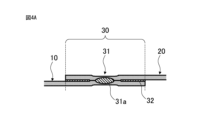
- FIG. 4 is a schematic diagram showing an example of a cross section of a joint between a first part and a second part in an automobile part, in which a foamed resin is present around a welded part.
- FIG. 4 is a schematic diagram showing a cross section taken along the line IV-IV in FIG. 3.
- FIG. 4 is a schematic diagram showing an example of a cross section of a joint between a first part and a second part in an automobile part, in which no foamed resin is present around the welded part.
- FIG. 3 is a schematic diagram showing a cross-sectional configuration taken along the line V-V in FIG. 2.
- FIG. 3 is a schematic diagram showing an example of a cross-sectional configuration of a portion of a joint between a first part and a second part in an automobile part that is not welded or mechanically joined (a portion away from a weld or a mechanical joint). 1 shows an example of a manufacturing process for an automobile part.
- 1 shows an example of a manufacturing process for an automobile part.
- the structure of the sandwich steel plate used in the evaluation of the loss factor is shown diagrammatically.
- the relationship between the air bubble ratio and the loss factor is shown.
- 1 shows a schematic diagram of the configuration of components used to evaluate the loudness of sound radiated from a panel.
- the figure shows the relationship between the area ratio of adhesive containing air bubbles and adhesive without air bubbles and the maximum panel radiation sound ratio (relative to the maximum panel radiation sound when 100% adhesive without air bubbles is applied).
- the figure shows the relationship between the area ratio of adhesive containing air bubbles and adhesive without air bubbles and the average panel radiation sound ratio (relative to the average panel radiation sound when 100% adhesive without air bubbles is applied).
- an automobile part 100 includes a first part 10, a second part 20, and a joint 30 that joins the first part 10 and the second part 20.
- the joint 30 includes one or both of a welded part 31 and a mechanical joint (not shown), as well as a foamed resin 32 that bonds the first part 10 and the second part 20.
- the automobile part 100 includes a first part 10 and a second part 20.
- the first part 10 and the second part 20 may be different parts from each other.
- the first part 10 may be, for example, a framework, a panel, or a part other than these.
- the second part may be, for example, a framework, a panel, or a part other than these.
- the first component 10 may be a skeleton
- the second component 20 may be a panel.
- the skeleton and the panel can be firmly joined via a joint 30 described below, and the presence of foamed resin 32 can enhance vibration damping between the skeleton and the panel. In other words, the transmission of vibration from the skeleton to the panel and from the panel to the skeleton can be suppressed.
- the first component 10 may be a skeleton
- the second component 20 may be a skeleton different from the first component 10.
- the first skeleton and the other skeleton can be firmly joined via a joint 30 described below, and the presence of the foamed resin 32 can increase the vibration damping between the first skeleton and the other skeleton. In other words, the transmission of vibration from the first skeleton to the other skeleton can be suppressed.
- the first component 10 may be a panel
- the second component 20 may be a panel different from the first component 10.
- the first panel and the other panel can be firmly joined via a joint 30 described below, and the presence of the foamed resin 32 can increase the vibration damping between the first panel and the other panel. In other words, the transmission of vibration from the first panel to the other panel can be suppressed.
- the skeleton may be any type of structure that is suitable for use in an automobile, and there are no particular limitations on the specific type.
- the skeleton may be, for example, a floor member, a side member, a cross member, or other member; a pillar, such as an A-pillar, a B-pillar, or a C-pillar; a sill, such as a side sill; or a floor cross.
- the panel may be any automobile panel, and its specific type is not particularly limited.
- the panel may be, for example, a floor panel, roof panel, inner panel, back panel, door, bonnet hood, wheel house, or cowl portion.
- Figures 2A to 2D show specific examples of combinations of a first part 10 and a second part 20.
- Figure 2A shows an automobile part having an A-pillar as the first member 10 and a roof panel as the second member 20.
- Figure 2B shows an automobile part having an inner panel of a wheel house as the first member 10 and an outer panel of the wheel house as the second member 20.
- Figure 2C shows an automobile part having a side sill as the first member 10 and a floor panel as the second member 20.
- Figure 2D shows an automobile part having a front side member as the first member 10 and a floor cross as the second member 20.
- the technology disclosed herein can be applied to various automobile parts.
- the material and shape of the first part 10 and the second part 20 may be any material that allows welding and/or mechanical joining.
- the material of the first part 10 and the second part 20 may be at least one material selected from, for example, metal materials, plastic materials, rubber materials, fiber reinforced plastic materials (FRP), etc.
- the first part 10 and the second part 20 may be made of the same material or different materials. In particular, when the material of one or both of the first part 10 and the second part 20 is a metal material, excellent strength is easily ensured. Also, when the material of one or both of the first part 10 and the second part 20 is a fiber reinforced plastic material, excellent strength is easily ensured.
- the type of metal material is not particularly limited, and may be at least one selected from iron, titanium, aluminum, magnesium, and alloys thereof.
- alloys include iron-based alloys (including stainless steel), Ti-based alloys, Al-based alloys, and Mg alloys.
- one or both of the first part 10 and the second part 20 may be made of steel.
- the steel is not particularly limited, and may be one that is standardized by the Japanese Industrial Standards (JIS), for example. Specific examples include carbon steel, alloy steel, and high-tensile steel used for general structures and machine structures.
- JIS Japanese Industrial Standards
- the components of the steel are not particularly limited, and may contain one or more of Mn, Si, P, Al, N, Cr, Mo, Ni, Cu, Ca, Mg, Ce, Hf, La, Zr, and Sb in addition to Fe and C.
- the steel may have a component that contains C, Si, Mn, P, S, Al, and N, with the balance being Fe and impurities.
- Fiber reinforced resin material is a matrix resin reinforced with a fiber material.
- the type of resin and fiber material is not particularly limited. FRP may be composed of only a matrix resin and a fiber material. Alternatively, FRP may contain various additives such as conductive particles, inorganic fillers, rubber materials, pigments, colorants, antioxidants, and flame retardants for the purpose of imparting functionality. FRP may be single-layered or multi-layered, and the number of layers may be selected according to the application.
- the matrix resin contained in the fiber reinforced resin material (FRP) is not particularly limited, and may be a thermoplastic resin, a thermosetting resin, or a combination of these. In particular, thermoplastic resins have good bending strength and excellent processability.
- thermoplastic resin per 100 parts by mass of the resin component.
- the matrix resin may be only a thermoplastic resin.
- thermoplastic resin that can be used for the matrix resin is not particularly limited, and may be, for example, one or more selected from polyolefins and their acid-modified products; polypropylene; polystyrene; polymethyl methacrylate; AS resin; ABS resin; thermoplastic aromatic polyesters such as polyethylene terephthalate and polybutylene terephthalate; polycarbonate; thermoplastic epoxy resins; polyimides; polyamides; polyamideimides; polyetherimides; polyethersulfones; polyphenylene ethers and their modified products; polyphenylene sulfide; polyoxymethylene; polyarylates; polyether ketones; polyether ether ketones; polyether ketone ketones; and nylons.
- the thermosetting resin that can be used for the matrix resin is not particularly limited, and may be, for example, one or more selected from epoxy resins, vinyl ester resins, phenolic resins, and urethane resins.
- the fiber material contained in the fiber reinforced resin material (FRP) is not particularly limited, and may be, for example, at least one selected from carbon fibers, boron fibers, silicon carbide fibers, glass fibers, aramid fibers, and the like.
- the fiber material may be long or short fiber.
- FRP containing carbon fiber has excellent strength.
- the type of carbon fiber may be, for example, PAN-based or pitch-based, and may be selected according to the purpose and use.
- the fiber material may be only one of the above-mentioned fibers, or a combination of multiple types.
- the reinforcing fiber substrate (prepreg) that serves as the substrate of the above-mentioned fiber material include a nonwoven substrate using chopped fiber, a cloth material using continuous fiber, and a unidirectional reinforcing fiber substrate (UD material). From the viewpoint of reinforcing effect, it is preferable to use a cloth material or a UD material as the reinforcing fiber substrate.
- the volume content Vf of the fiber material in the FRP is not particularly limited, but is preferably 20% by volume or more and 70% by volume or less from the viewpoint of strength and processability.
- the Vf of the fiber material in the FRP is more preferably 25% by volume or more or 30% by volume or more, and more preferably 65% by volume or less or 60% by volume or less.
- the measurement of Vf can be performed by a method known to those skilled in the art.
- the shapes of the first part 10 and the second part 20 may be determined according to the application.
- one or both of the first part 10 and the second part 20 may be a steel plate.
- the steel plate may be optionally surface-treated.
- the surface treatment may be at least one selected from various plating treatments such as zinc plating (hot-dip galvanizing, electrolytic zinc plating, etc.) and aluminum plating, chemical conversion treatments such as chromate treatment and non-chromate treatment, and physical surface roughening treatments such as sandblasting or chemical surface roughening treatments such as chemical etching, but is not limited to these.
- the steel plate may be subjected to alloy plating or multiple types of surface treatments.
- the surface treatment of the steel plate preferably includes at least a treatment aimed at imparting rust resistance.
- one or both of the first part 10 and the second part 20 may comprise a steel plate, and the steel plate may have a thickness of 0.3 mm or more and 5.0 mm or less.
- the thickness of the steel plate may be 0.5 mm or more and 3.0 mm or less, or 1.0 mm or more and 3.0 mm or less.
- the term "steel plate” is a concept that includes a molded product in which a bend or unevenness is imparted to a steel plate.
- one or both of the first part 10 and the second part 20 may comprise a steel plate, and the steel plate may have a tensile strength of 250 MPa or more and 2500 MPa or less, and may have the above-mentioned plate thickness.
- the tensile strength of the steel plate may be 300 MPa or more, 350 MPa or more, 400 MPa or more, 450 MPa or more, 500 MPa or more, 550 MPa or more, 600 MPa or more, 650 MPa or more, 700 MPa or more, 750 MPa or more, 780 MPa or more, 800 MPa or more, 850 MPa or more, 900 MPa or more, 950 MPa or more, 980 MPa or more, 1000 MPa or more, 1050 MPa or more, 1100 MPa or more, or 1200 MPa or more.
- "tensile strength" is in accordance with JIS Z 2241:2011.
- the joint 30 includes one or both of a welded portion 31 that joins the first component 10 and the second component 20 by welding, and a mechanical joint (not shown) that mechanically joins the first component 10 and the second component 20.
- the joint 30 includes a foamed resin 32 that bonds the first component 10 and the second component 20 together.
- the first part 10 and the second part 20 are firmly joined by one or both of the welded part 31 and the mechanical joint.
- a spot welded part is exemplified as the welded part 31 in Figs. 3, 4A, and 4B, the type of the welded part 31 is not limited thereto.
- the welded part 31 may be at least one type selected from, for example, a spot welded part, a resistance welded part, a seam welded part, a laser welded part, and an element welded part.
- the mechanical joint may be at least one type selected from, for example, a riveted joint, a hemmed joint, a drill screw joint, a bolted joint, and a friction stir welded part.
- the joint 30 may include at least one selected from a spot weld, a projection weld, an arc spot weld, a laser weld (linear, spot, O-shaped or C-shaped), a hemmed portion, a blind rivet joint, a self-piercing rivet joint, a resistance element weld, an element arc weld, and a friction stir spot weld. As shown in Figs.
- a portion in which the metal components are melted and solidified is formed in the portion pressurized by the electrode, and a corona bond in which the metal components are joined without melting can be formed around the nugget 31a.
- the "corona bond” refers to the portion where the first part and the second part are pressed together around the nugget.
- the shape, size, number, and interval of the welded portion 31 and the mechanical joint portion are not particularly limited as long as they can join the first part 10 and the second part 20.
- Appropriate welded portions 31 and mechanical joint portions may be adopted according to the thickness and material of the first part 10 and the second part 20, and according to the target joining strength.
- the welded portion 31 and the mechanical joint portion may be present around the welded portion 31 and the mechanical joint portion between the first part 10 and the second part 20.
- the welded portion 31 and the mechanical joint portion may be formed so as to penetrate the foamed resin 32.
- the foamed resin 32 may not be present around the welded portion 31 and the mechanical joint portion between the first part 10 and the second part 20.
- the foamed resin 32 may be disposed in a portion of the joint portion 30 away from the welded portion 31 and the mechanical joint portion (for example, between one welded portion 31 and another welded portion 31).
- the first part 10 and the second part 20 are bonded by the foamed resin 32.
- the foamed resin 32 By combining the foamed resin 32 with the above-mentioned welded part 31 and/or mechanical joint part in the joint 30, excellent vibration damping properties can be exhibited between the first part 10 and the second part 20. That is, the vibration in the first part 10 is attenuated by the foamed resin 32 and is less likely to propagate to the second part 20. In addition, the vibration in the second part 20 is attenuated by the foamed resin 32 and is less likely to propagate to the first part 10.
- the automobile part 100 has excellent vibration damping properties.
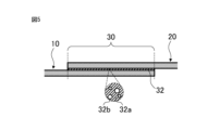
- the foamed resin 32 has resin 32a and air bubbles (voids) 32b.
- resin 32a There are no particular limitations on the type of resin 32a, as long as it is capable of bonding the first component 10 and the second component 20.
- the resin 32a exerts vibration damping properties by shear deformation, and the presence of air bubbles (voids) 32b together with the resin 32a induces shear deformation, further enhancing the vibration damping effect.
- the foamed resin 32 contains the air bubbles 32b together with the resin 32a, so that the foamed resin 32 has a high loss factor.
- the loss factor of the foamed resin 32 containing the air bubbles 32b is likely to be higher than the loss factor of the resin 32a alone.
- the resin 32a (cured resin) constituting the foamed resin 32 has a loss factor above a certain level and below a certain level, the effect of increasing the loss factor by introducing the air bubbles 32b is high.
- the amount of components that are not incorporated into the cross-linked structure of the cured resin increases, the cross-linking density of the cured resin decreases, and the elastic modulus decreases.
- the decrease in the elastic modulus of the cured resin increases the density of the strain energy concentrated at the interface between the voids caused by the air bubbles 32b and the resin 32a, thereby improving the loss factor and further enhancing the vibration damping effect.
- the elastic modulus will decrease excessively, making it difficult to maintain the shape and making it impossible to introduce air bubbles into the cured resin.
- the amount of resin components will decrease due to the air bubbles 32b escaping to the outside of the part together with the resin components, and the loss factor may decrease.
- the loss factor of the resin 32a alone is 0.02 or more and 0.25 or less
- the loss factor of the foamed resin 32 containing the air bubbles 32b is likely to be larger than the loss factor of the resin 32a alone that does not contain the air bubbles 32b.
- the foamed resin 32 may be obtained, for example, by forming a resin composition layer containing a resin component (A), a hardener (B), and a foaming agent (C) between the first part 10 and the second part 20, and then obtaining the above-mentioned resin 32a as a cured resin by a reaction between the resin component (A) and the hardener (B), and generating bubbles 32b by the foaming agent (C).
- the foamed resin 32 may contain components derived from the resin component (A) and the hardener (B), and components obtained after foaming of the foaming agent (C).
- the components contained in the foamed resin 32 can be identified by various analytical devices.
- the types and amounts of "components derived from the resin component (A) and the hardener (B)” and “components after foaming of the foaming agent (C)” can be identified, and the types and amounts of the resin component (A) and the hardener (B) can be identified from the types and amounts of "components derived from the resin component (A) and the hardener (B)", and the type and amount of the foaming agent (C) can be identified from the types and amounts of "components after foaming of the foaming agent (C)".
- the components contained in the foamed resin 32 can be identified by using a known method.
- a small amount of foamed resin can be directly and instantaneously thermally decomposed at high temperature by pyrolysis GC-MS (Gas Chromatography-Mass Spectrometry) measurement, and the generated gas components can be introduced into the GC-MS to analyze the components contained in the foamed resin.
- GC-MS Gas Chromatography-Mass Spectrometry
- the resin component (A) may be at least one selected from, for example, vinyl chloride resin, vinyl acetate resin, polyvinyl alcohol, polycarbonate, polyvinyl butyral, polystyrene, ABS resin, polymethyl methacrylate (methacrylic resin), polyphenylene oxide, polyurethane, ionomer resin, cellulose-based plastic, polyethylene, polypropylene, polyamide (nylon), polyacetal (polyoxymethylene), polyphenylene sulfide, vinylidene chloride resin, polyethylene terephthalate, fluororesin, phenolic resin, urea resin, melamine resin, unsaturated polyester resin, diallyl phthalate resin, epoxy resin, silicon resin, alkyd resin, polyimide, polyamino bismaleimide, casein resin, furan resin, and urethane resin.
- vinyl chloride resin vinyl acetate resin
- polyvinyl alcohol polycarbonate
- polyvinyl butyral polystyrene
- the curing agent (B) may be any agent that promotes the curing of the resin component (A).
- the curing agent (B) may be one or both of an amine-based curing agent and an acid anhydride curing agent, and when the resin component (A) is a urethane resin, the curing agent (B) may be a polyisocyanate compound, etc.
- the foaming agent (C) may be, for example, at least one selected from azodicarbonamide (ADCA), N,N'-dinitrosopentamethylenetetramine (DPT), 4,4'-oxybis(benzenesulfonylhydrazide) (OBSH), hydrazodicarbonamide (HDCA), barium azodicarboxylate, sodium hydrocarbyl, etc.
- the foaming agent (C) may be combined with a foaming assistant (D) as necessary.
- the foaming assistant (D) may be, for example, at least one selected from a urea-based assistant, a vulcanization accelerator, salicylic acid, zinc oxide, etc.
- An appropriate blending ratio is adopted depending on the amount of bubbles 32b (bubble rate) to be generated in the foamed resin 32. According to the knowledge of the inventor, if the amount of foaming agent (C) is too small, the effect of improving the loss factor is reduced, and if the amount of foaming agent (C) is too large, the foaming rate becomes too high, and the amount of resin 32a in the foamed resin 32 is reduced accordingly, and the effect of improving the loss factor may be reduced.
- the foamed resin 32 is obtained by foaming 0.1 parts by mass or more and 20 parts by mass or less of the foaming agent (C) with respect to 100 parts by mass of the resin component (A), the effect of improving the loss factor is significantly enhanced, and excellent vibration damping performance is easily ensured.
- the foamed resin 32 when the foamed resin 32 is obtained by foaming 0.5 parts by mass or more and 5 parts by mass or less of the foaming agent (C) with respect to 100 parts by mass of the resin (A), excellent vibration damping performance is easily ensured.
- the foaming rate of the foamed resin 32 may be, for example, 1% or more and 70% or less, preferably 3% or more and 50% or less, and more preferably 5% or more and 30% or less. The lower the foaming rate, the smaller the effect of increasing the loss factor. It is considered that the higher the foaming rate, the greater the effect of increasing the loss factor, but if the foaming rate is too high, the amount of the resin 32a becomes relatively small, and the loss factor may actually decrease.
- the foaming rate can be measured, for example, by an ultrasonic microscope.
- the bubble ratio of the foamed resin can be measured as follows. That is, a sample (a plate-shaped test piece in which a resin layer is sandwiched between two steel plates) is taken out from an automobile part, and the steel plates are placed in distilled water with the top and bottom facing up. A 10 mm x 10 mm field of view is observed at a portion 1 mm or more away from the edge of the sample (a portion toward the center of the sample) with a reflection-type scanning ultrasonic microscope at an ultrasonic frequency of 50 MHz, and image information of a scanning ultrasonic microscope image of 10 fields of view per sample is collected.
- the edges of the internal bubbles are binarized so that they can be recognized as circular or elliptical.
- the area of the binarized circular or elliptical section is regarded as the area of the bubbles observed from above the sample, and the total area ratio of the bubbles is obtained by image analysis, and the average value is obtained for the 10 fields of view, and the average value is regarded as the "bubble ratio".
- the bubble ratio of the foamed resin may be obtained in the same manner as above. The method for measuring the bubble ratio will be described in more detail in the examples described later.
- the resin composition of the foamed resin 32 before curing may contain a curing accelerator (E) as an optional component.
- the curing accelerator (E) may be selected appropriately depending on the type of resin component (A).
- the amount of the curing accelerator (E) depends on the type of the curing accelerator (E).
- the foamed resin 32 may also contain other additives.
- the other additives may be at least one selected from components that contribute to improving vibration damping properties, impact modifiers, adhesion promoters, defoamers, leveling agents, etc. Examples of components that contribute to improving vibration damping properties include rosin-based resins, etc.
- impact modifiers and adhesion promoters include at least one selected from core-shell type rubber particles, carboxyl-terminated butadiene nitrile rubber (CTBN), thermoplastic elastomers, and acrylic block copolymers, etc.
- CBN carboxyl-terminated butadiene nitrile rubber
- the foamed resin 32 includes the bubbles 32b.
- the loss factor ⁇ 1 of the automobile part 100 can be improved more than when the bubbles 32b are not introduced.
- the size of the bubbles 32b contained in the foamed resin 32 is 10 ⁇ m or more and 3000 ⁇ m or less
- the loss factor ⁇ 1 of the automobile part 100 is more easily improved.
- the size of the bubbles 32b may be 50 ⁇ m or more, 100 ⁇ m or more, 200 ⁇ m or more, or 300 ⁇ m or more, and may be 2500 ⁇ m or less, 2000 ⁇ m or less, or 1500 ⁇ m or less.
- These lower limit values and upper limit values may be any combination.
- bubble size refers to the "average circle-equivalent diameter of bubbles" measured by X-ray CT. Specifically, a three-dimensional image of the resin foam is obtained by X-ray CT. From the obtained three-dimensional image, information on a cross section that crosses the half-thickness position of the foam along the surface direction is obtained. Each of the multiple bubbles contained in the cross section is converted into a circle of the same area to determine the circle-equivalent diameter. The number average value of each circle-equivalent diameter is regarded as the "bubble size".
- X-ray CT measuring device Xradia520Versa (manufactured by ZEISS) Tube voltage: 30 kV Tube current: 0.67mA Magnification ratio: 0.4x (lens magnification) Analysis method: Analysis using Thermo Fisher Scientific's image analysis software "Avizo Inspect"
- Bubbles are identified by using two functions, Watershed (Separate Object) and Opening, of the image analysis software "Avizo Inspect" in the 3D images obtained by X-ray CT.
- Watershed is a method for identifying two connected bubbles as two bubbles rather than one. Specifically, a point that is a certain distance away from the bubble's outline is set as the bubble's core, and the area when the core is expanded until it touches the bubble's outline or another core is considered to be a bubble.
- Opening is a method for identifying each bubble when multiple connected bubbles form a dumbbell shape. Specifically, when a bubble is compressed, the axis of the dumbbell shape disappears, and the two separated bubbles can be identified. The bubble size is then returned to the original size by the amount of compression, and the area that disappeared can be identified as a single bubble from the difference between the images before and after compression.
- the elastic modulus of the resin constituting the foamed resin 32 (a portion of the foamed resin 32 excluding the bubbles 32b) is within a predetermined range, the effect of improving the loss factor ⁇ 1 by introducing the bubbles 32b tends to be more remarkable.
- the elastic modulus of the resin at 0 to 30° C. may be 1200 MPa or more and 3000 MPa or less.
- the elastic modulus may be 1500 MPa or more, 1750 MPa or more, or 2000 MPa or more, and may be 2750 MPa or less, 2500 MPa or less, or 2250 MPa or less.
- the loss factor ⁇ 1 is more likely to be improved.
- the "elastic modulus" of the resin refers to that measured by a tensile test.
- the foamed resin 32 is sandwiched between the first part 10 and the second part 20.
- the thickness of the foamed resin 32 (thickness of the adhesive layer) is thin enough to allow the above-mentioned welding or mechanical joining (e.g., spot welding).
- the thickness of the foamed resin 32 may be, for example, 1.0 ⁇ m or more and 1.0 mm or less, or 10 ⁇ m or more and 0.2 mm or less.
- the automobile part 100 has excellent vibration damping properties. For example, even if the thickness of the foamed resin 32 is 0.50 mm or less, excellent vibration damping performance can be exhibited.
- the thickness of the foamed resin 32 may be 0.10 mm or more and 0.50 mm or less.
- the thickness may be 0.15 mm or more, 0.20 mm or more, or 0.25 mm or more, and may be 0.45 mm or less, 0.40 mm or less, or 0.35 mm or less. These lower and upper limits may be any combination.
- the foamed resin 32 does not have to be present in the entire joint 30.
- a part of the first part 10 and a part of the second part 20 are overlapped, and the area ratio of the foamed resin 32 in the entire overlapping part of the first part 10 and the second part 20 may be 50% or more, 55% or more, 60% or more, 65% or more, 70% or more, 75% or more, or 80% or more.
- the upper limit of the area ratio of the foamed resin 32 depends on the area ratio of the spot welded part 31.
- a resin that does not contain air bubbles may be used in combination with the welded part 31, the mechanical joint, and the foamed resin 32.
- Loss factor ⁇ 1 According to the inventor's new findings, the effect of improving the loss factor ⁇ 1 by introducing the air bubbles 32b into the foamed resin 32 becomes remarkable, especially when the loss factor ⁇ 1 of the automobile part 100 is within a certain range. In a region where the loss factor ⁇ 1 of the automobile part 100 exceeds a certain value, the loss factor ⁇ 1 of the automobile part 100 is more likely to be increased when the foamed resin 32 does not contain air bubbles than when the foamed resin 32 contains air bubbles 32b.
- the loss factor ⁇ 1 of the automobile part 100 exceeds a certain value, the advantageous effect of introducing the air bubbles 32b into the foamed resin 32 is lost, and rather, there are cases where the automobile part 100 has better performance without introducing the air bubbles 32b.
- the loss factor ⁇ 1 of the automobile part 100 is below a certain value, the loss factor is difficult to improve even if the air bubbles 32b are introduced.
- the effect of improving the loss factor ⁇ 1 by introducing the bubbles 32b into the foamed resin 32 becomes significant when the automobile component 100 has a loss factor ⁇ 1 of 0.02 or more and 0.25 or less.
- the loss factor ⁇ 1 of the automobile component 100 when the loss factor ⁇ 1 of the automobile component 100 is 0.10 or more and 0.25 or less, the effect of introducing the bubbles is more excellent.
- the loss factor ⁇ 1 of the automobile component 100 may be 0.03 or more, 0.04 or more, 0.05 or more, 0.06 or more, 0.07 or more, 0.08 or more, 0.09 or more, 0.10 or more, 0.11 or more, or 0.12 or more, and may be 0.24 or less, 0.23 or less, 0.22 or less, 0.21 or less, or 0.20 or less.
- the effect of improving the loss factor ⁇ 1 of the automobile part 100 by introducing the air bubbles 32b is likely to be enhanced.
- the amount of components not incorporated into the crosslinked structure of the resin increases, the crosslink density of the cured product decreases, and the elastic modulus decreases.
- the decrease in the elastic modulus of the resin increases the density of the strain energy concentrated at the interface between the voids caused by the air bubbles and the resin, thereby improving the loss factor and further enhancing the vibration damping effect.
- the elastic modulus further decreases, making it difficult to maintain the shape, and it becomes impossible to introduce the air bubbles 32b into the foamed resin 32, making it difficult to contribute to an increase in the loss factor.
- the loss factor of the resin constituting the foamed resin 32 itself is 0.02 or more and 0.25 or less, the effect of increasing the loss factor by introducing the air bubbles is remarkable.
- the loss factor of the resin itself When the loss factor of the resin itself is less than 0.02, the elastic modulus is high and the density of the strain energy concentrated at the interface between the voids caused by the air bubbles and the resin is small, so the effect of increasing the loss factor by introducing air bubbles is small.
- the loss factor of the resin itself exceeds 0.25, the elastic modulus is very low, so it becomes difficult to maintain the shape, and air bubbles cannot be introduced into the cured resin, so the effect of increasing the loss factor is small.
- the "loss factor ⁇ 1 of an automobile part” refers to a loss factor measured by dynamic mechanical analysis (DMA) in a three-point bending mode at a measurement frequency of 10 Hz, and is the largest among the loss factors between 0°C and 30°C.
- DMA is a method for measuring the mechanical properties of a sample by applying a time-varying strain or stress (vibration) to the sample and measuring the resulting stress or strain.
- Vibration time-varying strain or stress
- the loss factor ⁇ 1 of an automobile part can be measured by placing a sample obtained by cutting out a part of the automobile part in a predetermined position of an apparatus for measuring the loss factor.
- the size of the sample is not particularly limited as long as the loss factor can be measured. For example, a sample having a width of 10 mm and a length of 20 to 55 mm is cut out from the automobile part using a cutter, and the loss factor is measured. The desirable size is 10 mm wide and 40 mm long.
- the sample does not include the mechanical joint. That is, a portion consisting of the first part, the second part, and the foamed resin arranged between them is cut out from the joint of the automobile part, and the loss factor ⁇ 1 is measured using this as a sample.
- a DMA7100 manufactured by Hitachi High-Tech Science Corporation is used as an apparatus for measuring the loss factor.
- the measurement conditions are two-cycle heating, in which the temperature is raised from -100°C to 200°C at 2°C/min, then the temperature is lowered from 200°C to -100°C, and the temperature is raised again from -100°C to 200°C at 2°C/min, the measurement frequency is set to 10Hz, and the loss factor at the second heating cycle is measured in three-point bending mode.
- the "loss factor of the resin (cured resin) itself constituting the foamed resin” In this case, a cured resin not containing air bubbles may be separately prepared and the loss factor may be measured in the same manner.
- the first plate-like member and the second plate-like member are peeled off to prepare the cured resin for measuring the loss factor.
- the loss factor of a composite consisting of the first plate-like member, the second plate-like member, and the cured resin sandwiched between them may be substantially the same as the loss factor of the cured resin regardless of the presence or absence of the first plate-like member and the second plate-like member (the influence of the plate itself on the loss factor is small).
- the loss factor of the composite itself may be measured without peeling off the first plate-like member and the second plate-like member, and this may be regarded as the loss factor of the cured resin itself.
- the manufacturing method of the automobile part 100 including the first part 10 and the second part 20 may include applying a resin composition to one or both of a part of the first part 10 and a part of the second part 20 (application step), adhering the first part 10 and the second part 20 via the resin composition (adhesion step), foaming the resin composition (foaming step), and performing one or both of welding and mechanical joining on the adhesion part between the first part 10 and the second part 20 (joining step).
- a resin composition is applied to one or both of a portion of the first component 10 and a portion of the second component 20.
- the resin composition may contain, for example, the above-mentioned resin component (A), curing agent (B), and foaming agent (C).
- the method of applying the resin composition is not particularly limited. For example, an applicator or the like may be used.
- the application area and application amount may be appropriately determined depending on the area, thickness, and the like of the foamed resin 32 to be finally obtained.
- the first component 10 and the second component 20 are adhered to each other via the above-mentioned resin composition.
- the first component 10 and the second component 20 can be adhered to each other by overlapping the first component 10 and the second component 20 with the resin composition therebetween and curing the resin composition by heating or the like. At this time, a foaming step described later may be performed.
- the heating means and heating temperature are not particularly limited.
- the resin composition is foamed. Specifically, the resin composition is heated, etc., to generate bubbles due to the action of the foaming agent (C) contained in the resin composition.
- the foaming step may be performed simultaneously with the adhesion step, or may be performed at a different time.
- the joining process In the joining process, one or both of welding and mechanical joining are performed on the bonding portion between the first component 10 and the second component 20.
- the "bonding portion" refers to a portion including the portion to which the resin composition is applied and which will ultimately become the bonding portion 30.
- the joining process may be performed after the curing or foaming of the resin composition, for example, as shown in FIG. 6A, or may be performed before that, as shown in FIG. 6B.
- the conditions for welding or mechanical joining are not particularly limited. The types of welding or mechanical joining are as described above.
- the two steel plates were bonded together via the adhesive by heating and pressing them with a hot press machine.
- the amount of foaming agent (C) contained in the adhesive was changed to prepare a plurality of sandwich steel plates with different foam ratios in the adhesive resin layer. Specifically, a sandwich steel plate A with a foam ratio of 0%, a sandwich steel plate B with a foam ratio of 6%, and a sandwich steel plate C with a foam ratio of 20% were obtained.
- the air bubble ratio of the adhesive resin layer in each sandwich steel plate was measured as follows.
- a 30 mm x 250 mm plate-shaped test piece (sample) was prepared in which a resin layer of 300 ⁇ m ⁇ 30 ⁇ m with different air bubble ratios was sandwiched between two 0.8 mmt steel plates, and the steel plates were placed in distilled water with the top and bottom facing up.
- a 10 mm x 10 mm field of view was observed from above with a reflection-type scanning ultrasonic microscope at an ultrasonic frequency of 50 MHz at the center side part 1 mm or more away from the edge of the sample, and image information of the scanning ultrasonic microscope image of five fields of view was collected.
- the area of the binarized circular or elliptical section was regarded as the area of the bubbles observed from above the sample, and the total area ratio of the bubbles was determined by image analysis, and the average value was determined in the 10 fields of view, and this average value was regarded as the "bubble ratio" (if a field of view of 10 mm x 10 mm cannot be secured due to the size of the sample, the "bubble ratio" can be determined by the above image analysis from the observation results in an area of 1000 mm2 in total in all fields of view).
- the reason why the sample was observed from both sides with an ultrasonic microscope as described above is that it is considered that the image of the entire resin layer of 300 ⁇ m thickness could not be obtained because ultrasonic waves are difficult to transmit through the resin and are attenuated.
- the bubble ratio can be considered to be uniform in the resin thickness direction, the bubble ratio can be determined by measuring with the above observation method even if the resin thickness is 300 ⁇ m or more.
- the influence of the chemical components and thickness of the steel plate can be substantially ignored, and substantially the same results can be obtained at least up to a steel plate thickness of 2.0 mm.
- the loss factor is improved by including air bubbles in the adhesive resin layer.
- a double hat-shaped frame (plate thickness: 1.0 mm) was bonded to both ends of a flat panel (side: 990 mm, thickness: 1.0 mm) with an adhesive resin layer, and spot welding (spot welding interval: 30 mm) was performed on the bonded portion.
- the vibration damping was evaluated. Specifically, vibration was applied to one end face of one frame, while the other end faces of the frame were fixed, and the magnitude of the radiation sound from the panel was evaluated by simulation.
- the noise level when the application area of the adhesive without air bubbles is 100% was set as the standard (100%), and the extent to which the noise level was reduced when part or all of the adhesive without air bubbles was replaced with an adhesive containing air bubbles was evaluated.
- Nastran of MSC Software was used as the analysis software.
- FIGS. 10A and 10B show the relationship between the application area ratio of the adhesive resin layer containing air bubbles ([application area of adhesive resin layer containing air bubbles]/[total application area of adhesive]) and the panel radiation sound.
- FIG. 10A shows the relationship between the area ratio of the adhesive containing air bubbles and the adhesive without air bubbles and the maximum panel radiation sound ratio (relative to the maximum panel radiation sound when 100% of the adhesive without air bubbles is applied as 100%)
- FIG. 10B shows the relationship between the area ratio of the adhesive containing air bubbles and the adhesive without air bubbles and the average panel radiation sound ratio (relative to the average panel radiation sound when 100% of the adhesive without air bubbles is applied as 100%).
- the panel radiation sound becomes smaller as the application area of the adhesive resin layer containing air bubbles increases, and it can be seen that the maximum panel radiation sound is particularly stable when the area ratio of the adhesive resin layer containing air bubbles is 50% or more.
- a form in which foamed resin is combined at the joint of an automobile part having a double hat member as a skeleton and a panel is exemplified, but the technology of the present disclosure is not limited to this form. It is believed that the predetermined effect can be achieved by adopting the technology of the present disclosure even when joining skeletons to skeletons or panels to panels.
- a form in which spot welding is used at the joint of an automobile part is exemplified, but the technology of the present disclosure is not limited to this form. It is believed that a part with excellent vibration damping properties can be obtained even when the joint is formed by welding or mechanical joining other than spot welding by combining the welding or mechanical joining with foamed resin.
- a form in which an automobile part is formed using steel plate is exemplified, but the material and shape of the automobile part are not limited to this.
- foamed resin in conjunction with welding and/or mechanical joining at the joints between the frame and the panel, and it is particularly preferable to use foamed resin in conjunction with welding (particularly spot welding) at the joints between the steel frame and the steel panel.
- An automobile part includes a first part, a second part, and a joint portion that joins the first part and the second part.
- the joint includes one or both of a weld and a mechanical joint, and a foamed resin that bonds the first component and the second component.
- a composite having a foamed resin between two steel plates is prepared using an epoxy resin (YD-127 manufactured by Nippon Steel Chemical & Material Co., Ltd.) or a copolymer polyester composition (Pylon (registered trademark) UR manufactured by Toyobo MC Co., Ltd.) as the resin (A), but the type of resin (A) applicable to the technology of the present disclosure is not limited to these.
- compositions shown in Tables 1 to 4 below those using DICY as the curing agent (B) were prepared as follows. First, a part of the resin (A) was set aside, and the foaming agent (C) and foaming assistant (D), the curing agent (B) (product name: DICY15), and the curing accelerator (E) (product name: DCMU) were uniformly dispersed using a three-roll mill to prepare composition X. All of the components shown in Tables 1 to 4 below, except for those used in the preparation of composition X, were weighed into a glass flask and mixed with heating at 150°C to obtain a uniform master batch.
- composition of the obtained resin composition is as shown in Tables 1 to 4 below.
- composition of the obtained resin composition is as shown in Tables 1 to 4 below.
- the loss factor ⁇ 1 of the obtained composite was measured.
- the measurement method of the loss factor ⁇ 1 was as described in the embodiment (the loss factor is the largest loss factor measured in a three-point bending mode at a measurement frequency of 10 Hz by dynamic viscoelasticity measurement at a temperature between 0°C and 30°C).
- Tables 1 to 4 show the composition of each resin composition, the curing temperature, the curing time, the presence or absence of air bubbles, the loss factor ⁇ 1 when air bubbles are present, and the loss factor ⁇ 2 when air bubbles are not present.
- "Kane Ace MX-154" in Tables 1 to 4 is a master batch in which 40% core-shell rubber is dispersed in 60% epoxy resin.
- the values in parentheses shown for the examples using "Kane Ace MX-154" are overall values obtained by dividing Kane Ace MX-154 into epoxy resin and core-shell rubber, and assuming resin (A) to be 100 parts by mass.
- the loss factor ⁇ 1 of the composite when air bubbles are included in the cured resin may be significantly improved compared to the loss factor ⁇ 2 of the composite when air bubbles are not included. It is considered that the inclusion of air bubbles in the cured resin concentrates strain energy at the interface between the voids of the air bubbles and the resin when the composite vibrates, thereby enhancing the vibration damping effect. Such an effect of introducing air bubbles is particularly noticeable when the loss factor ⁇ 1 of the composite is in the range of 0.02 to 0.25.
- the loss factor ⁇ 1 of the composite exceeds 0.25, the loss factor ⁇ 2 when air bubbles are not included is larger than the loss factor ⁇ 1 when air bubbles are included in the cured resin, that is, it can be seen that the effect of introducing air bubbles may be lost.
- the loss factor ⁇ 1 in the region where the loss factor ⁇ 1 is less than 0.02, the loss factor ⁇ 1 can be improved by including air bubbles in the cured resin, but the effect is small.
- the reason why the introduction of air bubbles does not contribute to the improvement of the loss factor ⁇ 1 in the region where the loss factor ⁇ 1 exceeds 0.25 is considered to be, for example, as follows: That is, when the loss factor is high and the elastic modulus is low (soft), the air bubbles escape together with the resin during foaming and curing, so that the air bubbles are not introduced into the resin in an appropriate form, and further, the amount of resin is reduced.
- the reason why the effect of improving the loss factor ⁇ 1 by introducing air bubbles decreases in a region where the loss factor ⁇ 1 is below 0.02 is, for example, considered to be as follows: That is, even if air bubbles are introduced into a resin having a small loss factor and a high elastic modulus (hard), when the composite vibrates, concentration of strain energy is unlikely to occur at the interface between the voids caused by the air bubbles and the resin, and it is possible that almost no vibration damping effect is obtained.
- the loss factor ⁇ 1 increases with increasing amount of foaming agent added up to 5 parts by mass relative to 100 parts by mass of resin. It is believed that this is because the increase in the amount of foaming agent added increases the bubble ratio in the cured resin, and air bubbles are appropriately and abundantly introduced.
- the amount of foaming agent added is 10 parts by mass or 20 parts by mass
- the loss modulus ⁇ 1 tends to be smaller than when the amount of foaming agent added is 5 parts by mass.
- the foaming agent is excessive, the foaming ratio becomes excessive, and the amount of resin decreases accordingly, which is believed to be the reason for the decrease in the loss factor.
- the foaming agent is excessive, in some cases, air bubbles may escape between the plates during the curing of the resin, and the air bubbles may not be properly introduced.
Landscapes
- Engineering & Computer Science (AREA)
- Chemical & Material Sciences (AREA)
- Combustion & Propulsion (AREA)
- Transportation (AREA)
- Mechanical Engineering (AREA)
- Laminated Bodies (AREA)
Abstract
優れた振動減衰性を有する自動車部品を開示する。 本開示の自動車部品は、第1部品、第2部品、及び、前記第1部品と前記第2部品とを接合する接合部、を備える。前記接合部は、溶接部及び機械的接合部のうちの一方又は両方、並びに、前記第1部品と前記第2部品とを接着する発泡樹脂、を備える。
Description
本願は自動車部品及び自動車部品の製造方法を開示する。
近年、自動車の車体強度を確保しつつ車体を軽量化するために、自動車部品の構成材料として超高張力鋼を採用するとともに、自動車部品を薄肉化することが行われている。一方、自動車部品の薄肉化によってロードノイズ等の振動による騒音が顕著になるという問題がある。例えば、自動車の足回り部品から骨格及びパネルを介して車内へと振動や騒音が伝搬され得る。この点、振動等を低減可能な制振性に優れる自動車部品が求められている。例えば、自動車部品として適用可能な各種の制振鋼板が開示されている(特許文献1等)。
従来の自動車部品は、制振性に関して、改善の余地がある。
本願は、上記課題を解決するための手段の一つとして、以下の複数の態様を開示する。
<態様1>
自動車部品であって、
第1部品、
第2部品、及び
前記第1部品と前記第2部品とを接合する接合部、
を備え、
前記接合部が、
溶接部及び機械的接合部のうちの一方又は両方、並びに
前記第1部品と前記第2部品とを接着する発泡樹脂、
を備える、
自動車部品。
<態様2>
態様1に記載の自動車部品であって、
前記接合部において、前記第1部品の一部と前記第2部品の一部とが重ね合わされており、
前記第1部品と前記第2部品の重ね合わせ部分の全体に占める前記発泡樹脂の面積率が、50%以上である、
自動車部品。
<態様3>
態様1又は2に記載の自動車部品であって、
前記発泡樹脂の気泡率が、1%以上70%以下である、
自動車部品。
<態様4>
態様1~3のいずれかの自動車部品であって、
前記発泡樹脂に含まれる気泡のサイズが、10μm以上3000μm以下である、
自動車部品。
<態様5>
態様1~4のいずれかの自動車部品であって、
0.02以上0.25以下の損失係数η1を有し、ここで前記損失係数η1は、動的粘弾性測定により測定周波数10Hzの3点曲げモードで測定される損失係数であって、0℃以上30℃以下の間における損失係数のうち最も大きいものである、
自動車部品。
<態様6>
態様1~5のいずれかの自動車部品であって、
前記第1部品及び前記第2部品のうちの一方又は両方が、鋼板を備え、
前記鋼板が、0.3mm以上5.0mm以下の板厚を有する、
自動車部品。
<態様7>
態様1~6のいずれかの自動車部品であって、
前記第1部品が、骨格であり、
前記第2部品が、パネルである、
自動車部品。
<態様8>
第1部品及び第2部品を備える自動車部品の製造方法であって、
前記第1部品の一部及び前記第2部品の一部のうちの一方又は両方に樹脂組成物を塗布すること、
前記樹脂組成物を介して、前記第1部品と前記第2部品とを接着すること、
前記樹脂組成物を発泡させること、及び
前記第1部品と前記第2部品との接着部分に溶接及び機械的接合のうちの一方又は両方を施すこと、を含む
製造方法。
<態様1>
自動車部品であって、
第1部品、
第2部品、及び
前記第1部品と前記第2部品とを接合する接合部、
を備え、
前記接合部が、
溶接部及び機械的接合部のうちの一方又は両方、並びに
前記第1部品と前記第2部品とを接着する発泡樹脂、
を備える、
自動車部品。
<態様2>
態様1に記載の自動車部品であって、
前記接合部において、前記第1部品の一部と前記第2部品の一部とが重ね合わされており、
前記第1部品と前記第2部品の重ね合わせ部分の全体に占める前記発泡樹脂の面積率が、50%以上である、
自動車部品。
<態様3>
態様1又は2に記載の自動車部品であって、
前記発泡樹脂の気泡率が、1%以上70%以下である、
自動車部品。
<態様4>
態様1~3のいずれかの自動車部品であって、
前記発泡樹脂に含まれる気泡のサイズが、10μm以上3000μm以下である、
自動車部品。
<態様5>
態様1~4のいずれかの自動車部品であって、
0.02以上0.25以下の損失係数η1を有し、ここで前記損失係数η1は、動的粘弾性測定により測定周波数10Hzの3点曲げモードで測定される損失係数であって、0℃以上30℃以下の間における損失係数のうち最も大きいものである、
自動車部品。
<態様6>
態様1~5のいずれかの自動車部品であって、
前記第1部品及び前記第2部品のうちの一方又は両方が、鋼板を備え、
前記鋼板が、0.3mm以上5.0mm以下の板厚を有する、
自動車部品。
<態様7>
態様1~6のいずれかの自動車部品であって、
前記第1部品が、骨格であり、
前記第2部品が、パネルである、
自動車部品。
<態様8>
第1部品及び第2部品を備える自動車部品の製造方法であって、
前記第1部品の一部及び前記第2部品の一部のうちの一方又は両方に樹脂組成物を塗布すること、
前記樹脂組成物を介して、前記第1部品と前記第2部品とを接着すること、
前記樹脂組成物を発泡させること、及び
前記第1部品と前記第2部品との接着部分に溶接及び機械的接合のうちの一方又は両方を施すこと、を含む
製造方法。
本開示の自動車部品は、優れた制振性を有する。
1.自動車部品
以下、図面を参照しつつ、本開示の自動車部品の一実施形態について説明する。ただし、本開示の自動車部品は、以下の実施形態に限定されるものではない。
以下、図面を参照しつつ、本開示の自動車部品の一実施形態について説明する。ただし、本開示の自動車部品は、以下の実施形態に限定されるものではない。
図1~5に示されるように、一実施形態に係る自動車部品100は、第1部品10、第2部品20、及び、前記第1部品10と前記第2部品20とを接合する接合部30、を備える。ここで、前記接合部30は、溶接部31及び機械的接合部(不図示)のうちの一方又は両方、並びに、前記第1部品10と前記第2部品20とを接着する発泡樹脂32、を備える。
1.1 第1部品及び第2部品
図1に示されるように、自動車部品100は、第1部品10及び第2部品20を備える。第1部品10と第2部品20とは、互いに異なる部品であればよい。第1部品10は、例えば、骨格であってもよいし、パネルであってもよいし、これら以外の部品であってもよい。また、第2部品は、例えば、骨格であってもよいし、パネルであってもよいし、これら以外の部品であってもよい。
図1に示されるように、自動車部品100は、第1部品10及び第2部品20を備える。第1部品10と第2部品20とは、互いに異なる部品であればよい。第1部品10は、例えば、骨格であってもよいし、パネルであってもよいし、これら以外の部品であってもよい。また、第2部品は、例えば、骨格であってもよいし、パネルであってもよいし、これら以外の部品であってもよい。
一実施形態において、第1部品10が骨格であり、第2部品20がパネルであってもよい。この場合、骨格とパネルとを後述の接合部30を介して強固に接合することができるとともに、発泡樹脂32の存在によって骨格とパネルとの間の制振性を高めることができる。すなわち、骨格からパネルへの振動の伝搬、及び、パネルから骨格への振動の伝搬を抑えることができる。
或いは、一実施形態において、第1部品10が骨格であり、第2部品20が第1部品10とは異なる骨格であってもよい。この場合、一の骨格と他の骨格とを後述の接合部30を介して強固に接合することができるとともに、発泡樹脂32の存在によって一の骨格と他の骨格との間の制振性を高めることができる。すなわち、一の骨格から他の骨格への振動の伝搬を抑えることができる。
或いは、一実施形態において、第1部品10がパネルであり、第2部品20が第1部品10とは異なるパネルであってもよい。この場合、一のパネルと他のパネルとを後述の接合部30を介して強固に接合することができるとともに、発泡樹脂32の存在によって一のパネルと他のパネルとの間の制振性を高めることができる。すなわち、一のパネルから他のパネルへの振動の伝搬を抑えることができる。
骨格は、自動車の骨格であればよく、その具体的な種類は特に限定されるものではない。骨格は、例えば、フロアメンバー、サイドメンバー、クロスメンバー等のメンバー;Aピラー、Bピラー、Cピラー等のピラー;サイドシル等のシル;又はフロアクロスであってもよい。
パネルは、自動車のパネルであればよく、その具体的な種類は特に限定されるものではない。パネルは、例えば、フロアパネル、ルーフパネル、インナーパネル、バックパネル、ドア、ボンネットフード、ホイールハウス又はカウル部であってもよい。
図2A~2Dに、第1部品10と第2部品20との組み合わせの具体例を示す。図2Aは、第1部材10としてのAピラーと、第2部材20としてのルーフパネルとを有する自動車部品である。図2Bは、第1部材10としてのホイールハウスの内パネルと、第2部材20としてのホイールハウスの外パネルとを有する自動車部品である。図2Cは、第1部材10としてのサイドシルと、第2部材20としてのフロアパネルとを有する自動車部品である。図2Dは、第1部材10としてのフロントサイドメンバーと、第2部材20としてのフロアクロスとを有する自動車部品である。図2A~2Dに示されるように、本開示の技術は、様々な自動車部品に適用可能である。
第1部品10及び第2部品20の材質や形状は、溶接及び/又は機械的接合が可能なものであればよい。第1部品10及び第2部品20の材質は、例えば、金属材料、ブラスチック材料、ゴム材料、繊維強化樹脂材料(FRP)等から選ばれる少なくとも1種であってもよい。第1部品10と第2部品20とは、互いに同じ材質であってもよいし、異なる材質であってもよい。特に、第1部品10及び第2部品20のうちの一方又は両方の材質が金属材料である場合に、優れた強度が確保され易い。また、第1部品10及び第2部品20のうちの一方又は両方の材質が繊維強化樹脂材料である場合にも、優れた強度が確保され易い。
金属材料の種類は、特に限定されず、例えば、鉄、チタン、アルミニウム、マグネシウム及びこれらの合金などから選ばれる少なくとも1種であってもよい。ここで、合金の例としては、例えば、鉄系合金(ステンレス鋼含む)、Ti系合金、Al系合金、Mg合金などが挙げられる。一実施形態において、第1部品10及び第2部品20のうちの一方又は両方は、鋼製であってもよい。鋼は、特に限定されないが、例えば、日本工業規格(JIS)等で規格されたものであってよい。具体的には、一般構造用や機械構造用として使用される炭素鋼、合金鋼、高張力鋼等が挙げられる。鋼の成分は、特に限定されないが、Fe、Cに加え、Mn、Si、P、Al、N、Cr、Mo、Ni、Cu、Ca、Mg、Ce、Hf、La、Zr及びSbの1種又は2種以上を含有してもよい。例えば、鋼材は、C、Si、Mn、P、S、Al及びNを含み、残部がFe及び不純物からなる成分を有していてもよい。
繊維強化樹脂材料(FRP)は、マトリクス樹脂を繊維材料で強化したものである。樹脂や繊維材料の種類は、特に限定されない。FRPは、マトリクス樹脂及び繊維材料のみからなっていてもよい。代替的に、FRPは、機能性を付与する等の目的のために、導電性粒子、無機フィラー、ゴム材料、顔料、着色剤、酸化防止剤、難燃剤等の各種の添加剤を含んでいてもよい。FRPは、単層であっても多層であってもよく、用途に応じて積層数が選択されればよい。繊維強化樹脂材料(FRP)に含まれるマトリクス樹脂は、特に限定されず、熱可塑性樹脂であってもよいし、熱硬化性樹脂であってもよいし、これらの組み合わせであってもよい。特に、熱可塑性樹脂は、良好な曲げ強度を有し、加工性にも優れる。例えば、樹脂成分100質量部に対して、50質量部以上、60質量部以上、70質量部以上、80質量部以上、又は90質量部以上の熱可塑性樹脂を含むとよい。マトリクス樹脂は、熱可塑性樹脂のみであってもよい。マトリクス樹脂に用いることができる熱可塑性樹脂は、特に制限されないが、例えば、ポリオレフィン及びその酸変性物;ポリプロピレン;ポリスチレン;ポリメチルメタクリレート;AS樹脂;ABS樹脂;ポリエチレンテレフタレートやポリブチレンテレフタレート等の熱可塑性芳香族ポリエステル;ポリカーボネート;熱可塑エポキシ樹脂;ポリイミド;ポリアミド;ポリアミドイミド;ポリエーテルイミド;ポリエーテルスルホン;ポリフェニレンエーテル及びその変性物;ポリフェニレンスルフィド;ポリオキシメチレン;ポリアリレート;ポリエーテルケトン;ポリエーテルエーテルケトン;ポリエーテルケトンケトン;並びにナイロン等から選ばれる1種又は2種以上であってもよい。マトリクス樹脂に用いることができる熱硬化性樹脂は、特に制限されないが、例えば、エポキシ樹脂、ビニルエステル樹脂、フェノール樹脂、及び、ウレタン樹脂から選ばれる1種又は2種以上であってもよい。繊維強化樹脂材料(FRP)に含まれる繊維材料は、特に限定されず、例えば、炭素繊維、ボロン繊維、シリコンカーバイド繊維、ガラス繊維、アラミド繊維等から選ばれる少なくとも1種であってもよい。繊維材料は、長繊維であっても短繊維であってもよい。特に炭素繊維を含むFRPは、優れた強度を有する。炭素繊維の種類は、例えば、PAN系、ピッチ系のいずれであってもよく、目的や用途に応じて選択され得る。繊維材料は、上述した繊維のうちの1種のみであってもよいし、複数種の組み合わせであってもよい。上記繊維材料の基材となる強化繊維基材(プリプレグ)としては、例えば、チョップドファイバーを使用した不織布基材や連続繊維を使用したクロス材、一方向強化繊維基材(UD材)などが挙げられる。補強効果の面からは、強化繊維基材としてクロス材やUD材を使用することが好ましい。FRP中の繊維材料の体積含有率Vfは、特に限定されないが、強度及び加工性の観点から、20体積%以上70体積%以下であると好ましい。FRP中の繊維材料のVfは、より好ましくは、25体積%以上又は30体積%以上であり、また、より好ましくは、65体積%以下又は60体積%以下である。Vfの測定は、当業者に公知の方法によって行うことができる。
第1部品10及び第2部品20の形状は、その用途に応じて決定されればよい。一実施形態において、第1部品10及び第2部品20のうちの一方又は両方は、鋼板であってもよい。鋼板は、任意に表面処理が施されたものであってもよい。ここで、表面処理とは、例えば、亜鉛めっき(溶融亜鉛めっき、電気亜鉛めっき等)及びアルミニウムめっきなどの各種めっき処理、クロメート処理及びノンクロメート処理などの化成処理、並びに、サンドブラストのような物理的若しくはケミカルエッチングのような化学的な表面粗化処理等から選ばれる少なくとも1種であってもよいが、これらに限定されるものではない。また、鋼板に対して、めっきの合金化や複数種の表面処理が施されていてもよい。鋼板に対する表面処理は、少なくとも防錆性の付与を目的とした処理を含むことが好ましい。
ここで、近年、自動車の車体強度を確保しつつ車体を軽量化するために、自動車部品の構成材料として超高張力鋼を採用するとともに、自動車部品を薄肉化することが行われているところ、自動車部品の薄肉化によってロードノイズ等の振動や騒音が伝播され易くなる。すなわち、第1部品10及び第2部品20のうちの一方又は両方が薄肉部品である場合に、振動や騒音に係る課題がより顕在化し易い。これに対し、本実施形態においては、後述するように接合部30において溶接部31及び機械的接合部のうちの一方又は両方とともに発泡樹脂32が組み合わされることで、高い制振性が確保され得る。すなわち、第1部品10及び第2部品20のうちの一方又は両方が薄肉部品である場合にも、自動車部品100は優れた制振性を有するものとなり、振動や騒音に係る課題を解決することができる。
一実施形態において、第1部品10及び第2部品20のうちの一方又は両方が、鋼板を備えるものであってよく、当該鋼板が、0.3mm以上5.0mm以下の板厚を有するものであってもよい。鋼板の板厚は、0.5mm以上3.0mm以下、又は、1.0mm以上3.0mm以下であってもよい。尚、本願において「鋼板」とは、鋼板に曲げや凹凸等を付与した成形物を含む概念である。
一実施形態において、第1部品10及び第2部品20のうちの一方又は両方が、鋼板を備えるものであってよく、当該鋼板が、250MPa以上2500MPa以下の引張強さを有し、かつ、上記の板厚を有するものであってよい。鋼板の引張強さは、300MPa以上、350MPa以上、400MPa以上、450MPa以上、500MPa以上、550MPa以上、600MPa以上、650MPa以上、700MPa以上、750MPa以上、780MPa以上、800MPa以上、850MPa以上、900MPa以上、950MPa以上、980MPa以上、1000MPa以上、1050MPa以上、1100MPa以上、1150MPa以上、1180MPa以上、1200MPa以上、1250MPa以上、1300MPa以上、1350MPa以上、1400MPa以上、1450MPa以上、又は、1470MPa以上であってもよく、また、2200MPa以下、2000MPa以下、1800MPa以下、1500MPa以下、1300MPa以下、又は、1180MPa以下であってもよい。尚、本願において「引張強さ」とは、JIS Z 2241:2011にしたがうものである。
1.2 接合部
図1に示されるように、自動車部品100においては、接合部30を介して、上記の第1部品10と第2部品20とが接合されている。図3、4A及び4Bに示されるように、接合部30は、第1部品10と第2部品20とを溶接によって接合する溶接部31、及び、第1部品10と第2部品20とを機械的に接合する機械的接合部(不図示)、のうちの一方又は両方を備える。また、図5に示されるように、接合部30は、第1部品10と第2部品20とを接着する発泡樹脂32を備える。
図1に示されるように、自動車部品100においては、接合部30を介して、上記の第1部品10と第2部品20とが接合されている。図3、4A及び4Bに示されるように、接合部30は、第1部品10と第2部品20とを溶接によって接合する溶接部31、及び、第1部品10と第2部品20とを機械的に接合する機械的接合部(不図示)、のうちの一方又は両方を備える。また、図5に示されるように、接合部30は、第1部品10と第2部品20とを接着する発泡樹脂32を備える。
1.2.1 溶接部及び機械的接合部
自動車部品100の接合部30においては、第1部品10と第2部品20とが溶接部31及び機械的接合部のうちの一方又は両方によって強固に接合される。図3、4A及び4Bには、溶接部31としてスポット溶接部を例示しているが、溶接部31の種類はこれに限定されるものではない。溶接部31は、例えば、スポット溶接部、抵抗溶接部、シーム溶接部、レーザー溶接部及びエレメント溶接部から選ばれる少なくとも1種であってもよい。一方、機械的接合部は、例えば、リベット接合部、ヘム加工接合部、ドリルネジ接合部、ボルト接合部及び摩擦攪拌接合部等から選ばれる少なくとも1種であってもよい。より具体的には、接合部30は、スポット溶接部、プロジェクション溶接部、アークスポット溶接部、レーザー溶接部(直線状、スポット状、O字状又はC字状)、ヘム加工部、ブラインドリベット接合部、セルフピアシングリベット接合部、抵抗エレメント溶接部、エレメントアーク溶接部及び摩擦攪拌点接合部等から選ばれる少なくとも1種を含むものであってもよい。図4A及び4Bに示されるように、第1部品10及び第2部品20に対してスポット溶接がなされた場合、電極により加圧された部分にナゲット31aと呼ばれる金属成分が溶融凝固した部分が形成され、ナゲット31aの周囲に金属成分が溶融せずに接合したコロナボンドが形成され得る。尚、「コロナボンド」とは、ナゲットの周囲に形成された第1部品と第2部品とが圧接された箇所である。
自動車部品100の接合部30においては、第1部品10と第2部品20とが溶接部31及び機械的接合部のうちの一方又は両方によって強固に接合される。図3、4A及び4Bには、溶接部31としてスポット溶接部を例示しているが、溶接部31の種類はこれに限定されるものではない。溶接部31は、例えば、スポット溶接部、抵抗溶接部、シーム溶接部、レーザー溶接部及びエレメント溶接部から選ばれる少なくとも1種であってもよい。一方、機械的接合部は、例えば、リベット接合部、ヘム加工接合部、ドリルネジ接合部、ボルト接合部及び摩擦攪拌接合部等から選ばれる少なくとも1種であってもよい。より具体的には、接合部30は、スポット溶接部、プロジェクション溶接部、アークスポット溶接部、レーザー溶接部(直線状、スポット状、O字状又はC字状)、ヘム加工部、ブラインドリベット接合部、セルフピアシングリベット接合部、抵抗エレメント溶接部、エレメントアーク溶接部及び摩擦攪拌点接合部等から選ばれる少なくとも1種を含むものであってもよい。図4A及び4Bに示されるように、第1部品10及び第2部品20に対してスポット溶接がなされた場合、電極により加圧された部分にナゲット31aと呼ばれる金属成分が溶融凝固した部分が形成され、ナゲット31aの周囲に金属成分が溶融せずに接合したコロナボンドが形成され得る。尚、「コロナボンド」とは、ナゲットの周囲に形成された第1部品と第2部品とが圧接された箇所である。
溶接部31及び機械的接合部の各々の形状や大きさや数や間隔は、第1部品10及び第2部品20を接合可能である限り、特に限定されるものではない。第1部品10及び第2部品20の厚みや材質等に応じて、また、目標とする接合強度等に応じて、適当な溶接部31や機械的接合部が採用されればよい。また、図4Aに示されるように、第1部品10と第2部品20との間において、溶接部31や機械的接合部の周囲に発泡樹脂32が存在していてもよい。言い換えれば、溶接部31や機械的接合部は、発泡樹脂32を貫通するように形成されていてもよい。或いは、図4Bに示されるように、第1部品10と第2部品20との間において、溶接部31や機械的接合部の周囲に発泡樹脂32が存在していなくてもよい。言い換えれば、接合部30において、溶接部31や機械的接合部から離れた部分(例えば、一の溶接部31と他の溶接部31との間)に発泡樹脂32が配置されていてもよい。
1.2.2 発泡樹脂
図5に示されるように、自動車部品100の接合部30においては、第1部品10と第2部品20とが発泡樹脂32によって接着される。接合部30において上記の溶接部31及び/又は機械的接合部とともに発泡樹脂32が組み合わされることで、第1部品10と第2部品20との間で優れた制振性が発揮され得る。すなわち、第1部品10における振動が、発泡樹脂32によって減衰され、第2部品20へと伝搬し難くなる。また、第2部品20における振動が、発泡樹脂32によって減衰され、第1部品10へと伝搬し難くなる。例えば、第1部品10が骨格であり、第2部品20がパネルである場合において、自動車の走行時にロードノイズ等の振動が自動車の足回り部品から骨格へと伝搬したとしても、骨格からパネルへの振動の伝搬が抑制され、車内の振動や騒音が抑制され得る。このように、本実施形態に係る自動車部品100は、優れた制振性を有する。
図5に示されるように、自動車部品100の接合部30においては、第1部品10と第2部品20とが発泡樹脂32によって接着される。接合部30において上記の溶接部31及び/又は機械的接合部とともに発泡樹脂32が組み合わされることで、第1部品10と第2部品20との間で優れた制振性が発揮され得る。すなわち、第1部品10における振動が、発泡樹脂32によって減衰され、第2部品20へと伝搬し難くなる。また、第2部品20における振動が、発泡樹脂32によって減衰され、第1部品10へと伝搬し難くなる。例えば、第1部品10が骨格であり、第2部品20がパネルである場合において、自動車の走行時にロードノイズ等の振動が自動車の足回り部品から骨格へと伝搬したとしても、骨格からパネルへの振動の伝搬が抑制され、車内の振動や騒音が抑制され得る。このように、本実施形態に係る自動車部品100は、優れた制振性を有する。
図5に示されるように、発泡樹脂32は、樹脂32aと気泡(空隙)32bとを有する。樹脂32aの種類に特に制限はなく、第1部品10と第2部品20とを接着可能なものであればよい。自動車部品100においては、例えば、樹脂32aがせん断変形することで制振性を発揮し、かつ、当該樹脂32aとともに気泡(空隙)32bが存在することで、せん断変形を誘発し、制振効果が一層高まるものと考えられる。
すなわち、発泡樹脂32が樹脂32aとともに気泡32bを含むことで、発泡樹脂32が高い損失係数を有するものとなる。言い換えれば、樹脂32a単独での損失係数よりも、気泡32bを含む発泡樹脂32の損失係数のほうが高くなり易い。特に、発泡樹脂32を構成する樹脂32a(硬化樹脂)が一定以上かつ一定以下の損失係数を有する場合に、気泡32bを導入したことによる損失係数の上昇効果が高くなる。例えば、硬化樹脂において種々の添加剤を配合することで、硬化樹脂の架橋構造に組み込まれない成分量が増加し、硬化樹脂の架橋密度が低下して、弾性率が低下する。硬化樹脂の弾性率が低下することで、気泡32bによる空隙と樹脂32aの界面に集中するひずみエネルギーの密度が高まり、それにより損失係数が向上し、制振効果が一層高まる。ただし、硬化樹脂の損失係数をさらに高めるため、添加剤量を増やし過ぎると、弾性率が過剰に低下し、形状を保持することが難しくなり、硬化樹脂への気泡の導入ができなくなる、気泡32bの導入時に樹脂成分とともに気泡32bが部品外に逃げるなどして樹脂成分量が低下し、損失係数が低下する場合がある。この点、樹脂32a単独での損失係数が、0.02以上0.25以下である場合、気泡32bを含む発泡樹脂32の損失係数が、気泡32bを含まない樹脂32a単独での損失係数よりも大きくなり易い。
発泡樹脂32は、例えば、第1部品10と第2部品20との間に、樹脂成分(A)と硬化剤(B)と発泡剤(C)とを含む樹脂組成物層を形成したうえで、樹脂成分(A)と硬化剤(B)との反応によって硬化樹脂としての上記樹脂32aを得るとともに、発泡剤(C)によって気泡32bを発生させてなるものであってよい。すなわち、発泡樹脂32は、樹脂成分(A)及び硬化剤(B)に由来する成分や、発泡剤(C)の発泡後の成分を含んでいてもよい。発泡樹脂32に含まれる成分は、各種の分析装置によって特定可能である。例えば、発泡樹脂32に含まれる成分を分析することによって、「樹脂成分(A)及び硬化剤(B)に由来する成分」や「発泡剤(C)の発泡後の成分」の種類や量が特定され、「樹脂成分(A)及び硬化剤(B)に由来する成分」の種類や量から、樹脂成分(A)や硬化剤(B)の各々の種類や量が特定され、「発泡剤(C)の発泡後の成分」の種類や量から、発泡剤(C)の種類や量が特定され得る。本実施形態において、発泡樹脂32に含まれる成分は、公知の方法を用いることにより特定することができる。例えば、以下の例に限定されないが、熱分解GC-MS(Gas Chromatography-Mass Spectrometry)測定によって、微量の発泡樹脂を直接高温下で瞬間的に熱分解し、発生したガス成分をGC-MSに導入することで、発泡樹脂に含まれる成分を分析することができる。
樹脂成分(A)は、例えば、塩化ビニル樹脂、酢酸ビニル樹脂、ポリビニルアルコール、ポリカーボネート、ポリビニルブチラール、ポリスチレン、ABS樹脂、ポリメタクリル酸メチル(メタクリル樹脂)、ポリフェニレンオキシド、ポリウレタン、アイオノマー樹脂、セルロース系プラスチック、ポリエチレン、ポリプロピレン、ポリアミド(ナイロン)、ポリアセタール(ポリオキシメチレン)、ポリフェニレンサルファイド、塩化ビニリデン樹脂、ポリエチレンテレフタレート、フッ素樹脂、フェノール樹脂、ユリア樹脂、メラミン樹脂、不飽和ポリエステル樹脂、ジアリルフタレート樹脂、エポキシ樹脂、ケイ素樹脂、アルキド樹脂、ポリイミド、ポリアミノビスマレイミド、カゼイン樹脂、フラン樹脂、及び、ウレタン樹脂等から選ばれる少なくとも1種であってもよい。
硬化剤(B)は、樹脂成分(A)の硬化を促進させるものであればよい。例えば、樹脂成分(A)がエポキシ樹脂である場合、硬化剤(B)は、アミン系硬化剤及び酸無水物硬化剤のうちの一方又は両方であってもよく、樹脂成分(A)がウレタン樹脂である場合、硬化剤(B)は、ポリイソシアネート化合物等であってもよい。
発泡剤(C)は、例えば、アゾジカルボンアミド(ADCA)、N,N’-ジニトロソペンタメチレンテトラミン(DPT)、4,4’-オキシビス(ベンゼンスルホニルヒドラジド)(OBSH)、ヒドラゾジカルボンアミド(HDCA)、バリウムアゾジカルボキシレート、及び、炭化水素ナトリウム等から選ばれる少なくとも1種であってもよい。また、気泡発生温度を調整するため、必要に応じて上記発泡剤(C)と発泡助剤(D)とが組み合わされてもよい。発泡助剤(D)は、例えば、尿素系助剤、加硫促進剤、サリチル酸及び酸化亜鉛等から選ばれる少なくとも1種であってもよい。
発泡樹脂32を形成するにあたって、上記の樹脂成分(A)、硬化剤(B)及び発泡剤(C)の配合比率に特に制限はない。発泡樹脂32に生じさせる気泡32bの量(気泡率)等に応じて、適切な配合比率が採用される。本発明者の知見によると、発泡剤(C)が少な過ぎると、損失係数の向上効果が低下し、また、発泡剤(C)が多過ぎると、発泡率が高くなり過ぎて、その分発泡樹脂32に占める樹脂32aの量が低下し、損失係数の向上効果が低下する虞がある。また、発泡剤(C)が多過ぎると、樹脂成分(A)の硬化中に第1部材10と第2部材20との隙間から発泡とともに樹脂成分(A)が逃げ易く、結果として、気泡がうまく導入されず、損失係数の向上効果が低下する虞がある。本発明者の知見によると、発泡樹脂32が、100質量部の前記樹脂成分(A)に対して、0.1質量部以上20質量部以下の前記発泡剤(C)を発泡させたものである場合に、損失係数の向上効果が顕著に高まり、優れた制振性能が確保され易い。特に、発泡樹脂32が、100質量部の前記樹脂(A)に対して、0.5質量部以上5質量部以下の前記発泡剤(C)を発泡させたものである場合に、より優れた制振性能が確保され易い。発泡樹脂32の気泡率は、例えば、1%以上70%以下であってもよく、望ましくは3%以上50%以下、さらに望ましくは5%以上30%以下であるとよい。気泡率が低いほど、上記の損失係数を上昇させる効果が小さい。気泡率が高いほど、上記の損失係数を上昇させる効果が高まるものと考えられるが、気泡率が高過ぎると、相対的に樹脂32aの量が少なくなり、損失係数がむしろ低下する可能性がある。尚、気泡率は、例えば、超音波顕微鏡により測定することができる。第1部品及び第2部品が鋼板からなる部品である場合、発泡樹脂の気泡率は、以下の通りに測定することができる。すなわち、自動車部品から試料(鋼板2枚で、樹脂層をサンドイッチした板状試験片)を取り出し、蒸留水中に鋼板が天地になるように入れて、反射型の走査超音波顕微鏡で、超音波振動数50MHzにて、試料の端から1mm以上離れた部分(試料中心側の部分)で10mm×10mmの視野を観察し、1試料10視野の走査超音波顕微鏡像の画像情報を採取する。その画像情報において、内部の気泡の縁が円状又は楕円状に認識できるように2値化する。その2値化した円状又は楕円状の区画の面積を試料上から観察した気泡の面積とし、気泡の全体の面積率を画像解析で求め、前記10視野で平均値を求めて、当該平均値を「気泡率」とする。尚、第1部品及び第2部品が鋼板以外の部品である場合も、上記と同様にして発泡樹脂の気泡率を求めればよい。気泡率の測定方法については、後述の実施例においてさらに詳細に説明する。
発泡樹脂32の硬化前の樹脂組成物中には、任意の成分として、硬化促進剤(E)が含まれていてもよい。硬化促進剤(E)は、樹脂成分(A)の種類等に応じて適切なものが選択されればよい。硬化促進剤(E)の配合量は、硬化促進剤(E)の種類による。また、発泡樹脂32には、その他の添加剤が含まれていてもよい。その他の添加剤は、制振性の向上に寄与する成分、耐衝撃性改質剤、接着性付与剤、消泡剤、レベリング剤等から選ばれる少なくとも1種であってもよい。制振性向上に寄与する成分としては、例えば、ロジン系樹脂等が挙げられる。また、耐衝撃性改質剤や接着性付与剤としては、コアシェル型ゴム粒子、カルボキシル基末端ブタジエンニトリルゴム(CTBN)、熱可塑性エラストマー及びアクリル系ブロック共重合体等から選ばれる少なくとも1種が挙げられる。
上述の通り、発泡樹脂32は、気泡32bを含む。発泡樹脂32において気泡32bが導入されることで、気泡32bが導入されなかった場合よりも、自動車部品100の損失係数η1を向上させることができる。特に、発泡樹脂32に含まれる気泡32bのサイズが10μm以上3000μm以下である場合、自動車部品100の損失係数η1を一層向上させ易い。損失係数η1をより一層向上させる観点から、気泡32bのサイズは、50μm以上、100μm以上、200μm以上又は300μm以上であってもよく、2500μm以下、2000μm以下又は1500μm以下であってもよい。。これら下限値及び上限値は任意の組み合わせであってよい。
本願において「気泡のサイズ」とは、X線CTにより測定される「気泡の平均円相当直径」をいう。具体的には、X線CTにより樹脂発泡樹脂の3次元画像を取得する。取得された3次元画像から、発泡樹脂の1/2厚さ位置を面方向に沿って横切る断面の情報を取得する。当該断面に含まれる複数の気泡の各々について同じ面積の円に換算し、円相当直径を求める。各々の円相当直径の数平均値を「気泡のサイズ」とみなす。X線CTの測定条件等は以下の通りである。
X線CT測定装置:Xradia520Versa(ZEISS社製)
管電圧:30kV
管電流:0.67mA
拡大軸率:0.4倍(レンズ倍率)
解析方法:サーモフィッシャーサイエンティフィック社製の画像解析ソフト「Avizo Inspect」により解析
X線CT測定装置:Xradia520Versa(ZEISS社製)
管電圧:30kV
管電流:0.67mA
拡大軸率:0.4倍(レンズ倍率)
解析方法:サーモフィッシャーサイエンティフィック社製の画像解析ソフト「Avizo Inspect」により解析
気泡の識別方法について、さらに詳細に説明する。気泡は、X線CTで得られた3次元像を、画像解析ソフト「Avizo Inspect」のWatershed(Separate Object)とOpeningとの2つの機能を用いることで識別する。Watershedとは2つの気泡が連なる場合に、1つの気泡ではなく2つの気泡として識別する手法である。具体的には、気泡の輪郭から一定以上の距離が離れている点を気泡のコアと設定し、そのコアを気泡の輪郭または別のコアに接触するまで拡大させたときの領域を気泡とみなす手法である。Openingは、複数の気泡が連なることでダンベル状となった場合に、各々の気泡を識別する手法である。具体的には、気泡を圧縮させるとダンベル形状の軸部分は消滅し、2つに分離した気泡を識別できる。次いで圧縮した分だけ気泡サイズを戻すと、圧縮前と後の画像との差から消滅した領域を1つの気泡として識別できる。
自動車部品100においては、発泡樹脂32を構成する樹脂(発泡樹脂32のうち気泡32bを除いた部分)の弾性率が所定範囲内である場合に、気泡32bが導入されたことによる損失係数η1の向上効果が一層顕著となる傾向にある。例えば、0~30℃における樹脂の弾性率は、1200MPa以上3000MPa以下であってもよい。当該弾性率は、1500MPa以上、1750MPa以上又は2000MPa以上であってもよく、2750MPa以下、2500MPa以下又は2250MPa以下であってもよい。特に、当該弾性率が1750MPa以上2250MPa以下であり、かつ、気泡31のサイズが上述した所定の範囲内である場合に、損失係数η1を一層向上させ易い。尚、本願において樹脂の「弾性率」は、引張試験によって測定されたものをいう。
図3及び4に示されるように、発泡樹脂32は、第1部品10と第2部品20とによって挟み込まれる。発泡樹脂32の厚み(接着層の厚み)は、上記の溶接や機械的接合(例えばスポット溶接)が可能な程度に薄い。発泡樹脂32の厚みは、例えば、1.0μm以上1.0mm以下であってもよく、10μm以上0.2mm以下であってもよい。本実施形態においては、発泡樹脂32の厚みが薄くとも、自動車部品100が優れた制振性を有するものとなる。例えば、発泡樹脂32の厚みが0.50mm以下である場合においても、優れた制振性能が発揮され得る。発泡樹脂32の厚みは、0.10mm以上0.50mm以下であってもよい。当該厚みは、0.15mm以上、0.20mm以上、又は、0.25mm以上であってもよく、0.45mm以下、0.40mm以下、又は、0.35mm以下であってもよい。これら下限値及び上限値は任意の組み合わせであってよい。
自動車部品100においては、接合部30に占める発泡樹脂32の面積率が高いほど、優れた制振性が発揮されるものと考えられる。ただし、発泡樹脂32は、接合部30の全体に存在しなくてもよい。この点、例えば、接合部30において、前記第1部品10の一部と前記第2部品20の一部とが重ね合わされており、前記第1部品10と前記第2部品20の重ね合わせ部分の全体に占める前記発泡樹脂32の面積率が、50%以上、55%以上、60%以上、65%以上、70%以上、75%以上又は80%以上であってもよい。発泡樹脂32の面積率の上限は、上記のスポット溶接部31の面積率による。尚、接合部30においては、上記の溶接部31、機械的接合部及び発泡樹脂32とともに、気泡を含まない樹脂等が併用されていてもよい。
1.3 損失係数η1
本発明者の新たな知見によると、自動車部品100の損失係数η1が一定の範囲内となる場合に特に、発泡樹脂32において気泡32bが導入されることによる損失係数η1の向上効果が顕著なものとなる。自動車部品100の損失係数η1が一定の値を超えるような領域では、発泡樹脂32に気泡32bを含ませた場合よりも、発泡樹脂32に気泡を含ませなかった場合のほうが、自動車部品100の損失係数η1が高まり易い。すなわち、自動車部品100の損失係数η1が一定の値を超える領域では、発泡樹脂32中に気泡32bを導入したことによる有利な効果が失われ、むしろ、気泡32bを導入しないほうが優れた性能を有するものとなる場合がある。また、自動車部品100の損失係数η1が一定の値を下回る場合、気泡32bを導入しても損失係数が向上し難い。本発明者の新たな知見によると、発泡樹脂32に気泡32bを導入したことによる損失係数η1の向上効果は、自動車部品100が0.02以上0.25以下の損失係数η1を有する場合に顕著となる。特に、自動車部品100の損失係数η1が、0.10以上0.25以下である場合に、気泡導入による一層優れた効果が発揮される。自動車部品100の損失係数η1は、0.03以上、0.04以上、0.05以上、0.06以上、0.07以上、0.08以上、0.09以上、0.10以上、0.11以上又は0.12以上であってもよく、かつ、0.24以下、0.23以下、0.22以下、0.21以下又は0.20以下であってもよい。
本発明者の新たな知見によると、自動車部品100の損失係数η1が一定の範囲内となる場合に特に、発泡樹脂32において気泡32bが導入されることによる損失係数η1の向上効果が顕著なものとなる。自動車部品100の損失係数η1が一定の値を超えるような領域では、発泡樹脂32に気泡32bを含ませた場合よりも、発泡樹脂32に気泡を含ませなかった場合のほうが、自動車部品100の損失係数η1が高まり易い。すなわち、自動車部品100の損失係数η1が一定の値を超える領域では、発泡樹脂32中に気泡32bを導入したことによる有利な効果が失われ、むしろ、気泡32bを導入しないほうが優れた性能を有するものとなる場合がある。また、自動車部品100の損失係数η1が一定の値を下回る場合、気泡32bを導入しても損失係数が向上し難い。本発明者の新たな知見によると、発泡樹脂32に気泡32bを導入したことによる損失係数η1の向上効果は、自動車部品100が0.02以上0.25以下の損失係数η1を有する場合に顕著となる。特に、自動車部品100の損失係数η1が、0.10以上0.25以下である場合に、気泡導入による一層優れた効果が発揮される。自動車部品100の損失係数η1は、0.03以上、0.04以上、0.05以上、0.06以上、0.07以上、0.08以上、0.09以上、0.10以上、0.11以上又は0.12以上であってもよく、かつ、0.24以下、0.23以下、0.22以下、0.21以下又は0.20以下であってもよい。
また、上述の通り、発泡樹脂32を構成する樹脂そのもの(気泡32bを含まない場合の樹脂)が一定以上かつ一定以下の損失係数を有している場合にも、気泡32bを導入したことによる自動車部品100の損失係数η1の向上効果が高まり易い。例えば、樹脂に対して上述の添加剤を配合することで、樹脂の架橋構造に組み込まれない成分量が増加し、硬化物の架橋密度が低下して、弾性率が低下する。樹脂の弾性率が低下することで、気泡による空隙と樹脂の界面に集中するひずみエネルギーの密度が高まり、それにより損失係数が向上し、制振効果が一層高まる。ただし、発泡樹脂32の損失係数をさらに高めるため、添加剤量を増やすと、弾性率がさらに低下し、形状を保持することが難しくなり、発泡樹脂32への気泡32bの導入ができなくなり、損失係数の上昇に寄与し難くなる。本発明者の知見によれば、発泡樹脂32を構成する樹脂そのもの(気泡32bを含まない場合の樹脂)の損失係数が0.02以上0.25以下である場合、気泡導入による損失係数の上昇効果が顕著である。樹脂そのものの損失係数が0.02に満たない場合、弾性率が高く、気泡による空隙と樹脂との界面に集中するひずみエネルギーの密度が小さいため、気泡導入による損失係数の上昇効果が小さくなる。また、樹脂そのものの損失係数が0.25を超えると、弾性率が非常に低いため、形状を保持することが難しくなり、樹脂硬化物へと気泡の導入ができなくなり、損失係数の上昇効果が小さくなる。
尚、本願において「自動車部品の損失係数η1」とは、動的粘弾性測定(DMA)により測定周波数10Hzの3点曲げモードで測定される損失係数であって、0℃以上30℃以下の間における損失係数のうち最も大きいものである。DMAとは、試料に時間によって変化する歪みまたは応力(振動)を与えて、それによって発生する応力又は歪みを測定することにより、試料の力学的な性質を測定する方法である。DMAにより試料の粘弾性特性として、貯蔵弾性率、損失弾性率、損失係数等の温度依存性や周波数依存性を測定することが可能であり、その中でも損失係数は一般的に振動減衰性能の指標として用いられる。自動車部品の損失係数η1は、自動車部品の一部を切り出して得られるサンプルを、損失係数を測定する装置の所定の位置に配置することによって、測定することができる。サンプルのサイズは、損失係数を測定可能である限り、特に限定されるものではない。例えば、自動車部品から、幅10mm、長さ20~55mmのサンプルを、切断機を用いて切り出して、損失係数を測定する。望ましいサイズは幅10mm、長さ40mmである。ここで、サンプルには機械的接合部を含ませない。すなわち、自動車部品の接合部から、第1部品、第2部品及びこれらの間に配置された発泡樹脂からなる部分を切り出し、これをサンプルとして損失係数η1を測定するものとする。損失係数を測定する装置としては、株式会社日立ハイテクサイエンス製DMA7100を使用する。測定条件は、-100℃から200℃にかけて2℃/minで昇温後、200℃から-100℃まで降温し、再び-100℃から200℃にかけて2℃/minで昇温する2サイクル昇温で、測定周波数を10Hzに設定し、3点曲げモードにて、2サイクル目の昇温時の損失係数を測定する。「発泡樹脂を構成する樹脂(硬化樹脂)そのものの損失係数」を測定する場合も同様である。この場合、気泡を含まない硬化樹脂を別途用意して損失係数を同様に測定すればよい。例えば、第1板状部材と第2板状部材との間に気泡を含まない硬化樹脂を形成した後、第1板状部材と第2板状部材とを剥がすことで、損失係数を測定するための硬化樹脂を用意できる。或いは、第1板状部材と第2板状部材とこれらの間に挟まれた硬化樹脂とからなる複合体の損失係数が第1板状部材及び第2板状部材の有無によらず、実質的に硬化樹脂の損失係数と同様である(板そのものが損失係数に与える影響が小さい)場合もある。この場合は、第1板状部材及び第2板状部材を剥がすことなく、複合体そのものの損失係数を測定し、これを硬化樹脂そのものの損失係数とみなしてもよい。
2.自動車部品の製造方法
自動車部品100は、例えば、以下の方法によって製造することができる。図6A及び6Bに示されるように、第1部品10及び第2部品20を備える自動車部品100の製造方法は、前記第1部品10の一部及び前記第2部品20の一部のうちの一方又は両方に樹脂組成物を塗布すること(塗布工程)、前記樹脂組成物を介して、前記第1部品10と前記第2部品20とを接着すること(接着工程)、前記樹脂組成物を発泡させること(発泡工程)、及び、前記第1部品10と前記第2部品20との接着部分に溶接及び機械的接合のうちの一方又は両方を施すこと(接合工程)、を含むものであってよい。
自動車部品100は、例えば、以下の方法によって製造することができる。図6A及び6Bに示されるように、第1部品10及び第2部品20を備える自動車部品100の製造方法は、前記第1部品10の一部及び前記第2部品20の一部のうちの一方又は両方に樹脂組成物を塗布すること(塗布工程)、前記樹脂組成物を介して、前記第1部品10と前記第2部品20とを接着すること(接着工程)、前記樹脂組成物を発泡させること(発泡工程)、及び、前記第1部品10と前記第2部品20との接着部分に溶接及び機械的接合のうちの一方又は両方を施すこと(接合工程)、を含むものであってよい。
2.1 塗布工程
塗布工程においては、第1部品10の一部及び第2部品20の一部のうちの一方又は両方に樹脂組成物を塗布する。樹脂組成物は、例えば、上述した樹脂成分(A)、硬化剤(B)及び発泡剤(C)等を含むものであってよい。樹脂組成物の塗布方法は特に限定されるものではない。例えば、アプリケータ等を用いられる。塗布面積や塗布量は、最終的に得られる発泡樹脂32の面積や厚み等に応じて適宜決定されればよい。
塗布工程においては、第1部品10の一部及び第2部品20の一部のうちの一方又は両方に樹脂組成物を塗布する。樹脂組成物は、例えば、上述した樹脂成分(A)、硬化剤(B)及び発泡剤(C)等を含むものであってよい。樹脂組成物の塗布方法は特に限定されるものではない。例えば、アプリケータ等を用いられる。塗布面積や塗布量は、最終的に得られる発泡樹脂32の面積や厚み等に応じて適宜決定されればよい。
2.2 接着工程
接着工程においては、上記の樹脂組成物を介して、第1部品10と第2部品20とを接着する。例えば、第1部品10と第2部品20とを樹脂組成物を介して重ね合わせたうえで、加熱等によって樹脂組成物を硬化させることで、第1部品10と第2部品20とを接着することができる。この時、後述の発泡工程が行われてもよい。加熱手段や加熱温度は特に限定されるものではない。
接着工程においては、上記の樹脂組成物を介して、第1部品10と第2部品20とを接着する。例えば、第1部品10と第2部品20とを樹脂組成物を介して重ね合わせたうえで、加熱等によって樹脂組成物を硬化させることで、第1部品10と第2部品20とを接着することができる。この時、後述の発泡工程が行われてもよい。加熱手段や加熱温度は特に限定されるものではない。
2.3 発泡工程
発泡工程においては、上記の樹脂組成物を発泡させる。具体的には、樹脂組成物を加熱すること等によって、樹脂組成物に含まれる発泡剤(C)の作用により気泡を生じさせる。発泡工程は、上記の接着工程と同時に行われてもよいし、異なるタイミングで行われてもよい。
発泡工程においては、上記の樹脂組成物を発泡させる。具体的には、樹脂組成物を加熱すること等によって、樹脂組成物に含まれる発泡剤(C)の作用により気泡を生じさせる。発泡工程は、上記の接着工程と同時に行われてもよいし、異なるタイミングで行われてもよい。
2.4 接合工程
接合工程においては、第1部品10と第2部品20との接着部分に溶接及び機械的接合のうちの一方又は両方を施す。「接着部分」とは、上記の樹脂組成物が塗布された部分を含み、かつ、最終的に接合部30となる部分である。接合工程は、例えば、図6Aに示されるように、上記の樹脂組成物の硬化や発泡の後に行われてもよいし、図6Bに示されるようにその前に行われてもよい。溶接や機械的接合の条件は、特に限定されるものではない。溶接や機械的接合の種類については上述の通りである。
接合工程においては、第1部品10と第2部品20との接着部分に溶接及び機械的接合のうちの一方又は両方を施す。「接着部分」とは、上記の樹脂組成物が塗布された部分を含み、かつ、最終的に接合部30となる部分である。接合工程は、例えば、図6Aに示されるように、上記の樹脂組成物の硬化や発泡の後に行われてもよいし、図6Bに示されるようにその前に行われてもよい。溶接や機械的接合の条件は、特に限定されるものではない。溶接や機械的接合の種類については上述の通りである。
以下、実施例を示しつつ本発明についてさらに説明するが、本発明は以下の実施例に限定されるものではない。本発明は、その要旨を逸脱せず、その目的を達する限りにおいては、種々の条件を採用可能とするものである。
1.損失係数の評価
第1部品と第2部品との接合部における損失係数の評価を模擬するため、図7に示されるような短冊状のサンドイッチ鋼板を作製し、損失係数の評価を行った。具体的には、30×250mmの平面矩形状で、厚み0.8mmである鋼板を2枚用意した。一方の鋼板の全面に接着剤(樹脂成分(A):エポキシ樹脂、硬化剤(B):ジシアンジアミド(DICY)、発泡剤(C):N,N’-ジニトロペンタメチレンテトラミン(DPT))を塗布した。塗布にはアプリケータを用いた。スペーサとともに他方の鋼板を重ね合わせた後、ホットプレス機にて加熱しつつ加圧保持することで、接着剤を介して2枚の鋼板を接着した。ここで、接着剤に含まれる発泡剤(C)の量を変更して、接着樹脂層における気泡率の異なる複数のサンドイッチ鋼板を作製した。具体的には、気泡率0%のサンドイッチ鋼板A、気泡率6%のサンドイッチ鋼板B、気泡率20%のサンドイッチ鋼板Cを得た。ここで、各々のサンドイッチ鋼板における接着樹脂層の気泡率は、以下の通り測定した。すなわち、0.8mmtの鋼板2枚で、気泡率を変えた樹脂層300μm±30μmをサンドイッチした30mm×250mmの板状試験片(試料)を用意し、蒸留水中に鋼板が天地になるように入れた。その上部から反射型の走査型超音波顕微鏡で、超音波振動数50MHzにて、試料の端から1mm以上離れた中心側部分で10mm×10mmの視野を観察し、5視野の走査超音波顕微鏡像の画像情報を採取した。試料の大きさにより10mm×10mmの視野が確保できない場合は、視野合計で500mm2の面積で測定すれば良い。さらに試料を裏返して同様の操作で5視野観察を行い、計1試料10視野の画像情報を得た(試料の大きさにより10mm×10mmの視野が確保できない場合は全視野合計で1000mm2の面積で測定すれば良い)。さらにその画像情報を内部の気泡の縁が円状又は楕円状に認識できるように2値化した。その2値化した円状又は楕円状の区画の面積を試料上から観察した気泡の面積とし、気泡の全体の面積率を画像解析で求め、前記10視野での平均値を求め、当該平均値を「気泡率」とした(試料の大きさにより10mm×10mmの視野が確保できない場合は全視野合計で1000mm2の面積での観察結果から上記画像解析により「気泡率」を求めることができる)。上記のように超音波顕微鏡で試料の表裏両面から観察した理由は、樹脂では、超音波が透過しにくく減衰してしまうため、樹脂層300μm厚全ての像は取得できていないと考えられるためである。一方、気泡率は樹脂厚さ方向では一様であるとみなせるため、樹脂厚さが300μm以上となっても上記観察方法で測定すれば気泡率を求めることができる。尚、上記超音波顕微鏡観察において、鋼板の化学成分や厚さによる影響は実質的に無視することができ、少なくとも鋼板厚さ2.0mmまでは実質的に同じ結果が得られる。
第1部品と第2部品との接合部における損失係数の評価を模擬するため、図7に示されるような短冊状のサンドイッチ鋼板を作製し、損失係数の評価を行った。具体的には、30×250mmの平面矩形状で、厚み0.8mmである鋼板を2枚用意した。一方の鋼板の全面に接着剤(樹脂成分(A):エポキシ樹脂、硬化剤(B):ジシアンジアミド(DICY)、発泡剤(C):N,N’-ジニトロペンタメチレンテトラミン(DPT))を塗布した。塗布にはアプリケータを用いた。スペーサとともに他方の鋼板を重ね合わせた後、ホットプレス機にて加熱しつつ加圧保持することで、接着剤を介して2枚の鋼板を接着した。ここで、接着剤に含まれる発泡剤(C)の量を変更して、接着樹脂層における気泡率の異なる複数のサンドイッチ鋼板を作製した。具体的には、気泡率0%のサンドイッチ鋼板A、気泡率6%のサンドイッチ鋼板B、気泡率20%のサンドイッチ鋼板Cを得た。ここで、各々のサンドイッチ鋼板における接着樹脂層の気泡率は、以下の通り測定した。すなわち、0.8mmtの鋼板2枚で、気泡率を変えた樹脂層300μm±30μmをサンドイッチした30mm×250mmの板状試験片(試料)を用意し、蒸留水中に鋼板が天地になるように入れた。その上部から反射型の走査型超音波顕微鏡で、超音波振動数50MHzにて、試料の端から1mm以上離れた中心側部分で10mm×10mmの視野を観察し、5視野の走査超音波顕微鏡像の画像情報を採取した。試料の大きさにより10mm×10mmの視野が確保できない場合は、視野合計で500mm2の面積で測定すれば良い。さらに試料を裏返して同様の操作で5視野観察を行い、計1試料10視野の画像情報を得た(試料の大きさにより10mm×10mmの視野が確保できない場合は全視野合計で1000mm2の面積で測定すれば良い)。さらにその画像情報を内部の気泡の縁が円状又は楕円状に認識できるように2値化した。その2値化した円状又は楕円状の区画の面積を試料上から観察した気泡の面積とし、気泡の全体の面積率を画像解析で求め、前記10視野での平均値を求め、当該平均値を「気泡率」とした(試料の大きさにより10mm×10mmの視野が確保できない場合は全視野合計で1000mm2の面積での観察結果から上記画像解析により「気泡率」を求めることができる)。上記のように超音波顕微鏡で試料の表裏両面から観察した理由は、樹脂では、超音波が透過しにくく減衰してしまうため、樹脂層300μm厚全ての像は取得できていないと考えられるためである。一方、気泡率は樹脂厚さ方向では一様であるとみなせるため、樹脂厚さが300μm以上となっても上記観察方法で測定すれば気泡率を求めることができる。尚、上記超音波顕微鏡観察において、鋼板の化学成分や厚さによる影響は実質的に無視することができ、少なくとも鋼板厚さ2.0mmまでは実質的に同じ結果が得られる。
作製したサンドイッチ鋼板A~Cの各々について、その中央を加振機に固定し、0~6000Hzまで加振して、1次曲げ~3次曲げの各々の場合における、加振点での加速度を測定するとともに、半値幅法を用いて損失係数を同定した。図8に、接着樹脂層の気泡率と損失係数との関係を示す。尚、図8においては、気泡なしのサンドイッチ鋼板Aについての損失係数を基準(1.0)として、サンドイッチ鋼板B及びサンドイッチ鋼板Cの各々の損失係数を相対化して示した。
図8に示されるように、接着樹脂層中に気泡を含ませることで、損失係数が向上することがわかる。
2.自動車部品への適用
図9に示されるように、平板状のパネル(一辺:990mm、厚さ:1.0mm)の両端にダブルハット型の骨格(板厚:1.0mm)を接着樹脂層によって接着するとともに、接着部分にスポット溶接(スポット溶接間隔:30mm)を施した場合について、制振性の評価を行った。具体的には、一つの骨格の一つの端面に対して振動を加える一方で、それ以外の骨格端面については固定し、パネルからの放射音の大きさをシミュレーションによって評価した。ここで、気泡を含まない接着剤の塗布面積が100%である場合の騒音レベルを基準(100%)とし、当該気泡を含まない接着剤の一部又は全部を、気泡を含む接着剤に置き換えた場合に騒音レベルがどの程度低下したかを評価した。解析ソフトにはMSCソフトウェアのNastranを用いた。
図9に示されるように、平板状のパネル(一辺:990mm、厚さ:1.0mm)の両端にダブルハット型の骨格(板厚:1.0mm)を接着樹脂層によって接着するとともに、接着部分にスポット溶接(スポット溶接間隔:30mm)を施した場合について、制振性の評価を行った。具体的には、一つの骨格の一つの端面に対して振動を加える一方で、それ以外の骨格端面については固定し、パネルからの放射音の大きさをシミュレーションによって評価した。ここで、気泡を含まない接着剤の塗布面積が100%である場合の騒音レベルを基準(100%)とし、当該気泡を含まない接着剤の一部又は全部を、気泡を含む接着剤に置き換えた場合に騒音レベルがどの程度低下したかを評価した。解析ソフトにはMSCソフトウェアのNastranを用いた。
図10A及び10Bに気泡を含む接着樹脂層の塗布面積比([気泡を含む接着樹脂層の塗布面積]/[接着剤の全体の塗布面積])とパネル放射音との関係を示す。図10Aが、気泡を含む接着剤及び気泡を含まない接着剤の面積比と最大パネル放射音比(気泡を含まない接着剤を100%塗布した場合の最大パネル放射音を100%として相対化したもの)と関係を示したものであり、図10Bが、気泡を含む接着剤及び気泡を含まない接着剤の面積比と平均パネル放射音比(気泡を含まない接着剤を100%塗布した場合の平均パネル放射音を100%として相対化したもの)と関係を示したものである。図10A及び10Bに示されるように、気泡を含む接着樹脂層の塗布面積が増加するほど、パネル放射音が小さくなり、特に最大パネル放射音は、気泡を含む接着樹脂層の面積率が50%以上で安定した効果が得られることが分かる。
尚、上記の実施例では、骨格としてのダブルハット部材とパネルとを備える自動車部品の接合部において、発泡樹脂を組み合わせる形態を例示したが、本開示の技術はこの形態に限定されるものではない。骨格と骨格とを接合する場合や、パネルとパネルとを接合する場合等においても、本開示の技術を採用することで、所定の効果が発揮されるものと考えられる。また、上記実施例では、自動車部品の接合部においてスポット溶接を採用する形態を例示したが、本開示の技術はこの形態に限定されるものではない。スポット溶接以外の溶接又は機械的接合によって接合部を形成する場合においても、当該溶接や機械的接合とともに発泡樹脂を組み合わせることで、制振性に優れる部品が得られるものと考えられる。また、上記の実施例では、鋼板を用いて自動車部品を構成する形態を例示したが、自動車部品の材質や形状はこれに限定されるものではない。
自動車の走行時に足回り部品から骨格を介してパネルへと伝わる振動等を抑制する観点からは、骨格とパネルとの接合部において、溶接及び/又は機械的接合とともに発泡樹脂を採用することが好ましく、鋼製の骨格と鋼製のパネルとの接合部において、溶接(特にスポット溶接)とともに発泡樹脂を採用することが特に好ましい。
3.まとめ
以上の結果から、以下の要件(1)及び(2)を満たす自動車部品は、制振性に優れるものといえる。
(1)自動車部品が、第1部品、第2部品、及び、前記第1部品と前記第2部品とを接合する接合部、を備える。
(2)前記接合部が、溶接部及び機械的接合部のうちの一方又は両方、並びに、前記第1部品と前記第2部品とを接着する発泡樹脂、を備える。
以上の結果から、以下の要件(1)及び(2)を満たす自動車部品は、制振性に優れるものといえる。
(1)自動車部品が、第1部品、第2部品、及び、前記第1部品と前記第2部品とを接合する接合部、を備える。
(2)前記接合部が、溶接部及び機械的接合部のうちの一方又は両方、並びに、前記第1部品と前記第2部品とを接着する発泡樹脂、を備える。
4.追加実験
以下の追加実験を行うことで、発泡樹脂及び自動車部品の接合部の好適な形態を検討した。
以下の追加実験を行うことで、発泡樹脂及び自動車部品の接合部の好適な形態を検討した。
4.1 樹脂組成物の作製
以下の実施例においては、樹脂(A)として、エポキシ樹脂(日鉄ケミカル&マテリアル社製YD-127)又は共重合ポリエステル組成物(東洋紡エムシー社製パイロン(登録商標)UR)を用いて、2枚の鋼板の間に発泡樹脂を備える複合体を作製した場合について例示するが、本開示の技術に適用可能な樹脂(A)の種類はこれらに限定されるものではない。
以下の実施例においては、樹脂(A)として、エポキシ樹脂(日鉄ケミカル&マテリアル社製YD-127)又は共重合ポリエステル組成物(東洋紡エムシー社製パイロン(登録商標)UR)を用いて、2枚の鋼板の間に発泡樹脂を備える複合体を作製した場合について例示するが、本開示の技術に適用可能な樹脂(A)の種類はこれらに限定されるものではない。
4.1.1 樹脂硬化物に気泡を導入する場合
下記表1~4に示される樹脂組成物のうち、硬化剤(B)としてDICYを用いたものについては、以下の通りに作製した。まず、樹脂(A)の一部を取り分け、発泡剤(C)及び発泡助剤(D)と、硬化剤(B)(商品名:DICY15)と、硬化促進剤(E)(商品名:DCMU)とを3本ロールミルで均一に分散させて組成物Xを調製した。下記表1~4に示される成分のうち、組成物Xの調製に用いた分を除く全成分をガラスフラスコに計量し、150℃にて加熱混合することにより、均一なマスターバッチを得た。次に、得られたマスターバッチを60℃以下に冷却した後、組成物Xを計量して添加し、60~70℃で加熱混合することによって均一に分散させ、樹脂組成物を得た。得られた樹脂組成物の組成は、下記表1~4に示される通りである。
下記表1~4に示される樹脂組成物のうち、硬化剤(B)としてDICYを用いたものについては、以下の通りに作製した。まず、樹脂(A)の一部を取り分け、発泡剤(C)及び発泡助剤(D)と、硬化剤(B)(商品名:DICY15)と、硬化促進剤(E)(商品名:DCMU)とを3本ロールミルで均一に分散させて組成物Xを調製した。下記表1~4に示される成分のうち、組成物Xの調製に用いた分を除く全成分をガラスフラスコに計量し、150℃にて加熱混合することにより、均一なマスターバッチを得た。次に、得られたマスターバッチを60℃以下に冷却した後、組成物Xを計量して添加し、60~70℃で加熱混合することによって均一に分散させ、樹脂組成物を得た。得られた樹脂組成物の組成は、下記表1~4に示される通りである。
下記表1~4に示される樹脂組成物のうち、硬化剤(B)としてTPPを用いたものについては、以下の通りに作製した。すなわち、下記表1~4に示される全成分をガラスフラスコに計量し、60~70℃で加熱混合することによって、樹脂組成物を得た。
4.1.2 樹脂硬化物に気泡を導入しない場合
下記表1~4に示される樹脂組成物のうち、硬化剤(B)としてDICYを用いたものについては、以下の通りに作製した。まず、樹脂(A)の一部を取り分け、硬化剤(B)(商品名:DICY15)と、硬化促進剤(E)(商品名:DCMU)とを3本ロールミルで均一に分散させて組成物Yを調製した。下記表1~4に示される成分のうち、組成物Yの調製に用いた分を除く全成分をガラスフラスコに計量し、150℃にて加熱混合することにより、均一なマスターバッチを得た。次に、得られたマスターバッチを60℃以下に冷却した後、組成物Yを計量して添加し、60~70℃で加熱混合することによって均一に分散させ、樹脂組成物を得た。得られた樹脂組成物の組成は、下記表1~4に示される通りである。
下記表1~4に示される樹脂組成物のうち、硬化剤(B)としてDICYを用いたものについては、以下の通りに作製した。まず、樹脂(A)の一部を取り分け、硬化剤(B)(商品名:DICY15)と、硬化促進剤(E)(商品名:DCMU)とを3本ロールミルで均一に分散させて組成物Yを調製した。下記表1~4に示される成分のうち、組成物Yの調製に用いた分を除く全成分をガラスフラスコに計量し、150℃にて加熱混合することにより、均一なマスターバッチを得た。次に、得られたマスターバッチを60℃以下に冷却した後、組成物Yを計量して添加し、60~70℃で加熱混合することによって均一に分散させ、樹脂組成物を得た。得られた樹脂組成物の組成は、下記表1~4に示される通りである。
下記表1~4に示される樹脂組成物のうち、硬化剤(B)としてTPPを用いたものについては、以下の通りに作製した。すなわち、下記表1~4に示される全成分をガラスフラスコに計量し、60~70℃で加熱混合することによって、樹脂組成物を得た。
4.2 複合体の作製
2枚の鋼板(厚み0.4mm)を用意した。上記の通りに得られた樹脂組成物を、アプリケータを用いて一定の厚みになるように、一方の鋼板に塗布した。塗布面に対して、PTFE製のスペーサとともに、もう一方の鋼板を重ね合わせることで、鋼板/樹脂組成物/鋼板からなる積層体を得た。積層体をホットプレス機にて所定の温度でプレス保持することで、鋼板/樹脂硬化物/鋼板からなる複合体(サンドイッチ鋼板)を得た。板厚方向における樹脂硬化物の厚みは400μmであった。得られた複合体を長さ40mm×幅10mmに切り出し、損失係数η1の測定用試験片とした。
2枚の鋼板(厚み0.4mm)を用意した。上記の通りに得られた樹脂組成物を、アプリケータを用いて一定の厚みになるように、一方の鋼板に塗布した。塗布面に対して、PTFE製のスペーサとともに、もう一方の鋼板を重ね合わせることで、鋼板/樹脂組成物/鋼板からなる積層体を得た。積層体をホットプレス機にて所定の温度でプレス保持することで、鋼板/樹脂硬化物/鋼板からなる複合体(サンドイッチ鋼板)を得た。板厚方向における樹脂硬化物の厚みは400μmであった。得られた複合体を長さ40mm×幅10mmに切り出し、損失係数η1の測定用試験片とした。
4.3 損失係数η1の測定
得られた複合体の損失係数η1を測定した。損失係数η1の測定方法については実施形態にて説明した通り(動的粘弾性測定により測定周波数10Hzの3点曲げモードで測定される損失係数であって、0℃以上30℃以下の間における損失係数のうち最も大きいもの)である。
得られた複合体の損失係数η1を測定した。損失係数η1の測定方法については実施形態にて説明した通り(動的粘弾性測定により測定周波数10Hzの3点曲げモードで測定される損失係数であって、0℃以上30℃以下の間における損失係数のうち最も大きいもの)である。
4.4 気泡の有無の確認
上記の試験片を切断し、その切断面を目視で観察することにより、気泡の有無を確認した。
上記の試験片を切断し、その切断面を目視で観察することにより、気泡の有無を確認した。
4.5 評価結果
下記表1~4に、各々の樹脂組成物の組成、硬化温度、硬化時間、気泡の有無、気泡を含む場合の損失係数η1、並びに、気泡を含まない場合の損失係数η2を示す。尚、表1~4の「カネエースMX-154」は、コアシェルゴム40%がエポキシ樹脂60%に分散されているマスターバッチである。表4において、「カネエースMX-154」を用いた例について示されるカッコ内の数値は、カネエースMX-154をエポキシ樹脂とコアシェルゴムとに分けて、樹脂(A)を100質量部として、全体的に整理した数値である。
下記表1~4に、各々の樹脂組成物の組成、硬化温度、硬化時間、気泡の有無、気泡を含む場合の損失係数η1、並びに、気泡を含まない場合の損失係数η2を示す。尚、表1~4の「カネエースMX-154」は、コアシェルゴム40%がエポキシ樹脂60%に分散されているマスターバッチである。表4において、「カネエースMX-154」を用いた例について示されるカッコ内の数値は、カネエースMX-154をエポキシ樹脂とコアシェルゴムとに分けて、樹脂(A)を100質量部として、全体的に整理した数値である。
表1~4に示される結果から、樹脂硬化物中に気泡を含ませた場合の複合体の損失係数η1が、気泡を含ませなかった場合の複合体の損失係数η2よりも顕著に向上する場合があることが分かる。樹脂硬化物が気泡を含むことで、複合体の振動時に、気泡による空隙と樹脂との界面に歪エネルギーが集中し、制振効果が高まった結果と考えられる。このような気泡導入による効果は、複合体の損失係数η1が0.02以上0.25以下の範囲内となる場合に特に顕著に生じる。複合体の損失係数η1が0.25を超えるような領域においては、樹脂硬化物に気泡を含ませた場合の損失係数η1よりも、気泡を含ませなかった場合の損失係数η2のほうが大きくなり、すなわち、気泡導入による効果が失われる場合があることがわかる。また、表1~4に示される結果から明らかなように、損失係数η1が0.02を下回るような領域においては、樹脂硬化物に気泡を含ませることで損失係数η1を向上させることができるものの、その効果は小さい。
損失係数η1が0.25を超える領域において、気泡の導入が損失係数η1の向上に寄与しない理由については、例えば、以下の通りと考えられる。すなわち、損失係数が高く、弾性率が低い(柔らかい)と、発泡及び硬化の際に樹脂とともに気泡が抜けてしまい、樹脂中に気泡が適切な形で導入されず、さらには、樹脂の量が少なくなったものと考えられる。
損失係数η1が0.02を下回る領域において、気泡の導入による損失係数η1の向上効果が低下する理由については、例えば、以下の通りと考えられる。すなわち、損失係数が小さく、弾性率が高い(硬い)樹脂に対して気泡を導入したとしても、複合体の振動時に、気泡による空隙と樹脂との界面に歪エネルギーの集中が生じ難く、制振効果がほとんど得られなかった可能性がある。
また、表1~4に示される結果から明らかなように、樹脂100質量部に対する発泡剤の添加量が5質量部までは、添加量が増加するにしたがって損失係数η1が大きくなる。発泡剤添加量が増加することで、樹脂硬化物中の気泡率が高まり、気泡が適切かつ多く導入されたことによるものと考えられる。一方で、発泡剤の添加量が10質量部や20質量部の場合、発泡剤の添加量が5質量部の場合よりも損失弾性率η1が小さくなる傾向にある。発泡剤が過剰となると、発泡率が過剰となって、その分だけ樹脂量が低下したことで、損失係数が低下したものと考えられる。また、発泡剤が過剰となると、場合によっては、樹脂の硬化中に板間から気泡が逃げてしまい、気泡がうまく導入されなかった可能性もある。
4.6 気泡のサイズに関する検討
上記の参考例7、17及び25について、樹脂硬化物に含まれる気泡のサイズ(平均円相当直径)を測定した。気泡のサイズの測定方法は、本明細書の実施形態にて説明した通りである。結果を下記表5に示す。
上記の参考例7、17及び25について、樹脂硬化物に含まれる気泡のサイズ(平均円相当直径)を測定した。気泡のサイズの測定方法は、本明細書の実施形態にて説明した通りである。結果を下記表5に示す。
表5に示される結果から明らかなように、樹脂硬化物に含まれる気泡のサイズが10μm以上3000μm以下である場合、損失係数η1の向上効果がより顕著に高まるものといえる。
100 自動車部品
10 第1部品
20 第2部品
30 接合部
31 機械的接合部
31a ナゲット
32 発泡樹脂
32a 樹脂
32b 気泡
10 第1部品
20 第2部品
30 接合部
31 機械的接合部
31a ナゲット
32 発泡樹脂
32a 樹脂
32b 気泡
Claims (8)
- 自動車部品であって、
第1部品、
第2部品、及び
前記第1部品と前記第2部品とを接合する接合部、
を備え、
前記接合部が、
溶接部及び機械的接合部のうちの一方又は両方、並びに
前記第1部品と前記第2部品とを接着する発泡樹脂、
を備える、
自動車部品。 - 請求項1に記載の自動車部品であって、
前記接合部において、前記第1部品の一部と前記第2部品の一部とが重ね合わされており、
前記第1部品と前記第2部品の重ね合わせ部分の全体に占める前記発泡樹脂の面積率が、50%以上である、
自動車部品。 - 請求項1又は2に記載の自動車部品であって、
前記発泡樹脂の気泡率が、1%以上70%以下である、
自動車部品。 - 請求項1~3のいずれか1項に記載の自動車部品であって、
前記発泡樹脂に含まれる気泡のサイズが、10μm以上3000μm以下である、
自動車部品。 - 請求項1~4のいずれか1項に記載の自動車部品であって、
0.02以上0.25以下の損失係数η1を有し、ここで前記損失係数η1は、動的粘弾性測定により測定周波数10Hzの3点曲げモードで測定される損失係数であって、0℃以上30℃以下の間における損失係数のうち最も大きいものである、
自動車部品。 - 請求項1~5のいずれか1項に記載の自動車部品であって、
前記第1部品及び前記第2部品のうちの一方又は両方が、鋼板を備え、
前記鋼板が、0.3mm以上5.0mm以下の板厚を有する、
自動車部品。 - 請求項1~6のいずれか1項に記載の自動車部品であって、
前記第1部品が、骨格であり、
前記第2部品が、パネルである、
自動車部品。 - 第1部品及び第2部品を備える自動車部品の製造方法であって、
前記第1部品の一部及び前記第2部品の一部のうちの一方又は両方に樹脂組成物を塗布すること、
前記樹脂組成物を介して、前記第1部品と前記第2部品とを接着すること、
前記樹脂組成物を発泡させること、及び
前記第1部品と前記第2部品との接着部分に溶接及び機械的接合のうちの一方又は両方を施すこと、を含む
製造方法。
Priority Applications (1)
| Application Number | Priority Date | Filing Date | Title |
|---|---|---|---|
| JP2025519341A JPWO2024232185A1 (ja) | 2023-05-09 | 2024-03-29 |
Applications Claiming Priority (2)
| Application Number | Priority Date | Filing Date | Title |
|---|---|---|---|
| JP2023077467 | 2023-05-09 | ||
| JP2023-077467 | 2023-05-09 |
Publications (1)
| Publication Number | Publication Date |
|---|---|
| WO2024232185A1 true WO2024232185A1 (ja) | 2024-11-14 |
Family
ID=93429986
Family Applications (1)
| Application Number | Title | Priority Date | Filing Date |
|---|---|---|---|
| PCT/JP2024/013080 Ceased WO2024232185A1 (ja) | 2023-05-09 | 2024-03-29 | 自動車部品及び自動車部品の製造方法 |
Country Status (2)
| Country | Link |
|---|---|
| JP (1) | JPWO2024232185A1 (ja) |
| WO (1) | WO2024232185A1 (ja) |
Cited By (1)
| Publication number | Priority date | Publication date | Assignee | Title |
|---|---|---|---|---|
| CN120945524A (zh) * | 2025-09-10 | 2025-11-14 | 广州帕卡汽车零部件有限公司 | 一种具有皮芯结构的长纤维、长纤维板和应用 |
Citations (6)
| Publication number | Priority date | Publication date | Assignee | Title |
|---|---|---|---|---|
| JPS6097842A (ja) * | 1983-11-02 | 1985-05-31 | 日東電工株式会社 | 金属板の制振防音方法 |
| JPS628853U (ja) * | 1985-07-03 | 1987-01-20 | ||
| JPH1081142A (ja) * | 1996-09-11 | 1998-03-31 | Tokai Rubber Ind Ltd | 車両用制振吸音部材 |
| JP2002028934A (ja) * | 2000-04-07 | 2002-01-29 | Pacific Ind Co Ltd | エンジンカバーおよびその製造方法 |
| JP2006316788A (ja) * | 2006-05-01 | 2006-11-24 | Tokai Rubber Ind Ltd | 低吸水・低吸油性防音材 |
| JP2009090522A (ja) * | 2007-10-05 | 2009-04-30 | Kobe Steel Ltd | 複合板および複合成形体 |
Family Cites Families (1)
| Publication number | Priority date | Publication date | Assignee | Title |
|---|---|---|---|---|
| KR20220089747A (ko) * | 2020-12-21 | 2022-06-29 | 주식회사 포스코 | 발포기공을 갖는 비구속형 제진 금속판 |
-
2024
- 2024-03-29 JP JP2025519341A patent/JPWO2024232185A1/ja active Pending
- 2024-03-29 WO PCT/JP2024/013080 patent/WO2024232185A1/ja not_active Ceased
Patent Citations (6)
| Publication number | Priority date | Publication date | Assignee | Title |
|---|---|---|---|---|
| JPS6097842A (ja) * | 1983-11-02 | 1985-05-31 | 日東電工株式会社 | 金属板の制振防音方法 |
| JPS628853U (ja) * | 1985-07-03 | 1987-01-20 | ||
| JPH1081142A (ja) * | 1996-09-11 | 1998-03-31 | Tokai Rubber Ind Ltd | 車両用制振吸音部材 |
| JP2002028934A (ja) * | 2000-04-07 | 2002-01-29 | Pacific Ind Co Ltd | エンジンカバーおよびその製造方法 |
| JP2006316788A (ja) * | 2006-05-01 | 2006-11-24 | Tokai Rubber Ind Ltd | 低吸水・低吸油性防音材 |
| JP2009090522A (ja) * | 2007-10-05 | 2009-04-30 | Kobe Steel Ltd | 複合板および複合成形体 |
Cited By (1)
| Publication number | Priority date | Publication date | Assignee | Title |
|---|---|---|---|---|
| CN120945524A (zh) * | 2025-09-10 | 2025-11-14 | 广州帕卡汽车零部件有限公司 | 一种具有皮芯结构的长纤维、长纤维板和应用 |
Also Published As
| Publication number | Publication date |
|---|---|
| JPWO2024232185A1 (ja) | 2024-11-14 |
Similar Documents
| Publication | Publication Date | Title |
|---|---|---|
| EP3288760B1 (en) | Weldable laminated structure and method of welding | |
| Patel et al. | Ultrasonic spot welding of aluminum to high-strength low-alloy steel: microstructure, tensile and fatigue properties | |
| Galvez et al. | Study of the behaviour of adhesive joints of steel with CFRP for its application in bus structures | |
| JP6053732B2 (ja) | 形成可能な軽量複合材 | |
| Naik et al. | A new method for joining metal and polymer sheets in sandwich panels for highly improved interface strength | |
| Huang et al. | Friction spot welding of carbon fiber-reinforced polyetherimide laminate | |
| Huang et al. | Effect of shot peening on static and fatigue properties of self-piercing riveting joints | |
| Huang et al. | Physical property and failure mechanism of self-piercing riveting joints between foam metal sandwich composite aluminum plate and aluminum alloy | |
| Krushnamurty et al. | Effect of nanoclay on the toughness of epoxy and mechanical, impact properties of E-glass-epoxy composites | |
| Ashong et al. | Refill friction stir spot welding of dissimilar AA6014 Al alloy and carbon-fiber-reinforced polymer composite | |
| WO2024232185A1 (ja) | 自動車部品及び自動車部品の製造方法 | |
| Li et al. | Current research and challenges in innovative technology of joining dissimilar materials for electric vehicles | |
| Wang et al. | Effect of process parameters on joint quality and mechanical properties of local-thickened self-piercing riveted steel and die-casting aluminum joints | |
| Kobayashi et al. | Joining process of dissimilar materials using three-dimensional electrodeposited Ni-Cu film | |
| Wang et al. | Research on the hybrid joining process and failure mode of laser welding and riveting on QP980 steel/CFRP | |
| Aufa et al. | Ultrasonic spot welding for joining dissimilar metals and composite materials | |
| Shi et al. | Effect of PA6 coating on the ultrasonic welding of CF/PA66 to 6061 aluminum alloy | |
| Ni et al. | Effects of plunge depth on the intermetallic compounds and mechanical properties of Al/Cu joints fabricated by micro friction stir welding | |
| Kumar et al. | Enhancing the performance of honeycomb core sandwich panels through friction stir spot welding strategies and fracture of lap shear specimen | |
| JP6693605B1 (ja) | 車両用構造部材 | |
| Kapil et al. | Enabling dissimilar joining of coated steels to aluminum through impact spot welding | |
| Harhash | Forming behaviour of multilayer metal/polymer/metal systems | |
| Zhao et al. | Ultrasonic welding of copper alloys: a review | |
| Lee et al. | Comparative analysis of SPR and SPR-bonded joints of hot press forming steel and AA5052 under corrosive conditions | |
| Peng et al. | Static strength analysis and experimental research of clinched joints by two-stroke flattening clinching method |
Legal Events
| Date | Code | Title | Description |
|---|---|---|---|
| 121 | Ep: the epo has been informed by wipo that ep was designated in this application |
Ref document number: 24803300 Country of ref document: EP Kind code of ref document: A1 |
|
| WWE | Wipo information: entry into national phase |
Ref document number: 2025519341 Country of ref document: JP |
|
| NENP | Non-entry into the national phase |
Ref country code: DE |