WO2024232182A1 - 側壁部の形成方法 - Google Patents
側壁部の形成方法 Download PDFInfo
- Publication number
- WO2024232182A1 WO2024232182A1 PCT/JP2024/013044 JP2024013044W WO2024232182A1 WO 2024232182 A1 WO2024232182 A1 WO 2024232182A1 JP 2024013044 W JP2024013044 W JP 2024013044W WO 2024232182 A1 WO2024232182 A1 WO 2024232182A1
- Authority
- WO
- WIPO (PCT)
- Prior art keywords
- side wall
- intermediate material
- angle
- wall portion
- top plate
- Prior art date
- Legal status (The legal status is an assumption and is not a legal conclusion. Google has not performed a legal analysis and makes no representation as to the accuracy of the status listed.)
- Ceased
Links
Images


Classifications
-
- B—PERFORMING OPERATIONS; TRANSPORTING
- B21—MECHANICAL METAL-WORKING WITHOUT ESSENTIALLY REMOVING MATERIAL; PUNCHING METAL
- B21D—WORKING OR PROCESSING OF SHEET METAL OR METAL TUBES, RODS OR PROFILES WITHOUT ESSENTIALLY REMOVING MATERIAL; PUNCHING METAL
- B21D19/00—Flanging or other edge treatment, e.g. of tubes
- B21D19/08—Flanging or other edge treatment, e.g. of tubes by single or successive action of pressing tools, e.g. vice jaws
-
- B—PERFORMING OPERATIONS; TRANSPORTING
- B21—MECHANICAL METAL-WORKING WITHOUT ESSENTIALLY REMOVING MATERIAL; PUNCHING METAL
- B21D—WORKING OR PROCESSING OF SHEET METAL OR METAL TUBES, RODS OR PROFILES WITHOUT ESSENTIALLY REMOVING MATERIAL; PUNCHING METAL
- B21D5/00—Bending sheet metal along straight lines, e.g. to form simple curves
- B21D5/02—Bending sheet metal along straight lines, e.g. to form simple curves on press brakes without making use of clamping means
- B21D5/0272—Deflection compensating means
-
- B—PERFORMING OPERATIONS; TRANSPORTING
- B21—MECHANICAL METAL-WORKING WITHOUT ESSENTIALLY REMOVING MATERIAL; PUNCHING METAL
- B21D—WORKING OR PROCESSING OF SHEET METAL OR METAL TUBES, RODS OR PROFILES WITHOUT ESSENTIALLY REMOVING MATERIAL; PUNCHING METAL
- B21D22/00—Shaping without cutting, by stamping, spinning, or deep-drawing
- B21D22/02—Stamping using rigid devices or tools
Definitions
- the present invention relates to a method for forming a side wall portion.
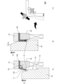
- FIG. 2(a) is a schematic cross-sectional view showing an example of such a bending process.
- FIG. 2 does not depict the entire material 100, but only a portion of one side wall portion 220 of the product 200 that is formed by the bending process.
- the end of the plate-shaped material 100 sandwiched between the first lower die 11 and the first pad 21, protruding from between the first lower die 11 and the first pad 21, is bent at a substantially right angle by the first bending blade 31 driven in the direction of the white arrow shown in the figure.
- a first intermediate material 110 is produced with an integrally formed side wall portion.
- the side wall portion opens due to springback, and the angle between the top plate portion and the side wall portion (hereinafter, sometimes referred to as the "flange angle") may become larger than an approximately right angle.
- a process called a "rise forming process” is widely performed as additional processing so that the flange angle becomes approximately a right angle as a result of the side wall portion opening due to springback after the bending process.
- the rise forming process is a process that offsets the amount of springback by pressing the side wall portion until the flange angle reaches the rise forming angle, which is an angle (acute angle) smaller than a right angle by an angle corresponding to the angle at which the side wall portion opens due to springback (hereinafter, sometimes referred to as the "springback amount").
- FIG. 2B is a schematic cross-sectional view showing an example of the above-mentioned bent portion forming process.
- the side wall portion of the first intermediate material 110 in which the top plate portion is sandwiched between the second lower die 12 and the first pad 21, and the angle of the corner facing the bent portion (boundary portion between the top plate portion and the side wall portion) of the first intermediate material 110 is an acute bent portion forming angle, is pushed in by the second bending blade 32 driven in the direction of the white arrow shown in the figure.
- the second intermediate material 120 is manufactured in which the angle (flange angle) between the top plate portion and the side wall portion is an acute bent portion forming angle (acute angle).
- the side wall portion opens due to springback, and the flange angle can become approximately a right angle.
- FIG. 2(c) is a schematic cross-sectional view showing an example of the above-mentioned edge cutting process.
- the surplus portion located at the tip of the side wall of the intermediate material 120, whose top plate portion is sandwiched between the third lower die 13 and the first pad 21 and whose side wall portion is sandwiched between the third lower die 13 and the second pad 22, is cut by the first punch 41 and the third lower die 13 driven in the direction of the white arrow shown in the figure.
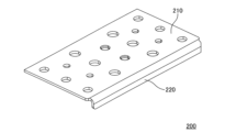
- scrap 300 is cut from the tip of the side wall of the intermediate material 120, and a product 200 having a top plate portion 210 and a side wall portion 220 that is erected at a substantially right angle from the end of the top plate portion 210 and has a desired length as shown in FIG. 1 is integrally formed.
- cutting off scrap 300 in the edge cutting process as described above leads to a waste of resources and causes a deterioration in product yield.
- the third lower die 13 when the length of the side wall portion 220 is short, as in the product 200 illustrated in FIG. 1, it is necessary to reduce the thickness (dimension in the extension direction of the side wall portion) of the third lower die 13 used in the above-mentioned edge cutting process. In other words, since the third lower die 13 needs to be thinned according to the required length of the side wall portion 220, as in the product 200, it may be difficult to configure the third lower die 13 to have durability that can withstand the stress and/or impact acting when the scrap 300 is cut off by the first punch 41.
- Patent Document 1 JP 2001-225111 A
- Patent Document 2 JP 2014-91140 A
- This method is said to improve the dimensional accuracy of the tip shape of the side wall, as well as impart sufficient compressive residual stress to improve fatigue strength.
- this method does not take into account the problem that, as mentioned above, when the product is removed from the mold after the bending process is completed, the side wall opens due to springback, causing the flange angle to become larger than a predetermined angle (for example, approximately a right angle).
- Patent Document 3 JP 2014-221493 A discloses a method of forming a box body having a top plate and side walls erected from the top plate by multiple warm press processes from a metal plate made of a specific material such as magnesium. This method is said to be able to provide a box body with sharp corners by simultaneously performing bending and/or drawing and coining. However, this method also does not take into consideration the problem that, as mentioned above, when the product is removed from the mold after the bending process is completed, the side walls open due to springback, causing the flange angle to become larger than a predetermined angle (for example, approximately a right angle).
- a predetermined angle for example, approximately a right angle
- a product having a top plate portion and a side wall portion (flange portion) erected at a predetermined angle (for example, approximately a right angle) from the end of the top plate portion is integrally formed from a plate-shaped material made of a general material by press working at room temperature, which can eliminate or reduce springback without performing the above-mentioned angle forming process as an additional process.
- a step forming process which is a process of pushing the sidewalls of the intermediate material toward the base end, by clamping the top plate of an intermediate material having a top plate and sidewalls that are integrally formed by bending the ends of the material at a predetermined first angle, and pushing back the sidewalls of the intermediate material until the flange angle, which is the angle between the top plate and the sidewalls, becomes equal to the first angle, until the flange angle matches the first angle, while maintaining this state.
- the method of forming a side wall portion according to the present invention is a method of forming a side wall portion in a construction method in which a product having a top plate portion and a side wall portion erected at a first angle, which is a predetermined angle, from an end of the top plate portion is integrally formed from a plate-shaped material by press working at room temperature.
- the method of the present invention includes the first to third steps listed below.
- the first step is to obtain an intermediate material having an integrally formed top plate and side wall by bending the end of the material at a first angle using bending and/or drawing.
- the second step is to clamp the top plate portion of the intermediate material between a first holding member arranged on the outside of the top plate portion of the intermediate material and a second holding member arranged on the inside of the top plate portion of the intermediate material.
- the third step is a step of changing the side wall portion of the intermediate material, which was in the first state, to the second state, and pressing the first end portion, which is the end portion on the tip side of the side wall portion of the intermediate material, toward the base end while maintaining the second state.
- the first state is a state in which the side wall portion of the intermediate material opens due to spring back and the flange angle, which is the angle between the top plate portion and the side wall portion of the intermediate material, is greater than the first angle.
- the second state is a state in which the side wall portion of the intermediate material is pushed back until the flange angle matches the first angle.
- the side wall of the intermediate material opens due to springback, causing the flange angle, which is the angle between the top plate and the side wall, to become larger than the desired first angle.
- the side wall of the intermediate material is pushed back until the flange angle becomes the first angle, while maintaining this state.
- the tip end of the side wall is pressed toward the base end. This eliminates or reduces the residual stress that causes springback in the intermediate material, and a product can be formed in which the flange angle matches the desired first angle.
- FIG. 1 is a schematic perspective view showing an example of a product having a top plate portion and a side wall portion erected at a substantially right angle from an end portion of the top plate portion.
- FIG. 1 is a schematic diagram showing an example of a conventional technique for forming a side wall portion erected at a substantially right angle from an end of a top plate portion.
- FIG. 4 is a flowchart illustrating a flow of steps included in a sidewall portion forming method (first method) according to the first embodiment of the present invention.
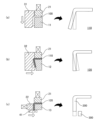
- 5A to 5C are schematic diagrams illustrating changes in shape during the molding process of a plate-shaped material into a product having a top plate portion and a side wall portion by the first method.
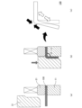
- FIG. 1 is a schematic diagram illustrating one specific means for obtaining an intermediate material having an integrally formed top plate portion and side wall portion by bending an end portion of the material at a first angle in a first step.
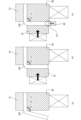
- FIG. 11 is a schematic diagram illustrating one specific means for pushing back the side wall portion of the intermediate material in a first state to change it to a second state in the third step while pressing the tip end (first end) of the side wall portion toward the base end.
- a schematic diagram illustrating how the third step is performed by advancing a punch having a predetermined shape in a first direction, which is a predetermined direction, in the side wall portion forming method (second method) according to the second embodiment of the present invention.
- FIG. 13 is a schematic diagram illustrating a state in which at least a portion including a first end of a side wall portion of an intermediate material is contained inside a closed space in a third step included in a method for forming a side wall portion (third method) according to a third embodiment of the present invention, and the first end is pressed toward the base end side.
- First Embodiment A method for forming a sidewall portion according to a first embodiment of the present invention (hereinafter, may be referred to as a "first method") will be described below.
- the first method is a method for forming a side wall portion in a method for integrally forming a product having a top plate portion and a side wall portion erected at a first angle, which is a predetermined angle, from a plate-shaped material by pressing at room temperature.
- the material constituting the material is not particularly limited as long as it is possible to obtain an intermediate material having a top plate portion and a side wall portion integrally formed by bending the end portion by bending and/or drawing. Specific examples of such materials include metals such as stainless steel, copper, and aluminum, and alloys containing these metals.
- the shape of the material is not particularly limited as long as at least the parts that will become the top plate portion and the side wall portion are plate-shaped, and may be planar or curved, and there may be non-plate-shaped parts in areas other than the parts that will become the top plate portion and the side wall portion.
- the shape of the material is, for example, a rectangular, elliptical, or circular flat plate.
- the number of side walls erected at the end of the top plate portion may be one or more. When there are more than one side walls, all of the side walls may be erected at the same first angle on the same side of the top plate portion, or some of the side walls may be erected at different first angles relative to the top plate portion. In the latter case, some of the side walls may be erected facing the opposite side of the top plate portion to the other side walls.
- the first method can also be applied to a construction method in which a ring-shaped side wall is provided to surround the periphery of the top plate portion to form a cylindrical product with a bottom.
- the first method includes the first to third steps described in detail below, as shown, for example, in the flow chart illustrated in FIG. 3.
- FIG. 3 is a flow chart illustrating the flow of each step included in the first method
- FIG. 4 is a schematic diagram illustrating the change in shape during the molding process of a plate-shaped material into a product having a top plate and side walls by the first method.
- FIGS. 4 and 5 depict only the portion of one side wall 220 of the product 200 that is formed by the bending process, rather than the entire material 100.
- the first process is first performed in step S10.
- the first process is a process for obtaining an intermediate material having an integrally formed top plate portion and side wall portion by bending the end portion of the material at a first angle by bending and/or drawing.
- the end portion of a plate-shaped material 100 as shown in FIG. 4(a) can be bent at a predetermined first angle ⁇ 1 by bending and/or drawing as shown by the black arrow in FIG. 4(b).
- FIG. 5 is a schematic diagram illustrating one specific means for obtaining an intermediate material 130 having a top plate portion 131 and a side wall portion 132 integrally formed by bending the end portion of the material 100 at a first angle ⁇ 1 in the first step as described above.
- the plate-shaped material 100 is sandwiched between the first lower die 11 and the first pad 21.
- the end portion of the material 100 protruding from between the first lower die 11 and the first pad 21 is bent at a predetermined first angle ⁇ 1 by the first bending blade 31 driven in the direction of the white arrow shown in the figure (see the arrow hatched with oblique lines in FIG. 5(b)).
- an intermediate material 130 having a top plate portion 131 and a side wall portion 132 integrally formed can be obtained.
- the first angle ⁇ 1 is typically a substantially right angle, but is not limited to a substantially right angle and can be any angle required for the final molded product.
- the side wall portion 132 may open due to springback, as shown by the open arrow in FIG. 4C.
- FIG. 5C tensile stress and compressive stress act on the outside and inside of the bent portion, which is the boundary between the top plate portion 131 and the side wall portion 132, respectively, when the material 100 is bent, resulting in residual stress in the contraction direction (black arrow) and stress in the expansion direction (open arrow) on the outside and inside of the bent portion of the intermediate material 130.
- the angle (flange angle ⁇ f) between the top plate portion 131 and the side wall portion 132 becomes a second angle ⁇ 2 that is larger than the desired first angle ⁇ 1.
- first state The state in which the side wall of the intermediate material opens due to spring back as described above, and the flange angle between the top plate and side wall of the intermediate material becomes an angle greater than the first angle, may be referred to as the "first state" hereinafter.
- the second step is executed in the next step S20, as illustrated in FIG. 3.
- the second step is a step of clamping the top plate portion of the intermediate material between a first holding member arranged on the outside of the top plate portion of the intermediate material and a second holding member arranged on the inside of the top plate portion of the intermediate material.
- a first holding member 51 e.g., a die
- a second holding member 52 e.g., a pad
- step S30 the third step is executed.
- the side wall portion of the intermediate material which was in the first state described above, is put into the second state, and the first end portion, which is the end portion on the tip side of the side wall portion of the intermediate material, is pressed toward the base end while maintaining the second state.
- the second state is a state in which the side wall portion of the intermediate material is pushed back until the flange angle matches the first angle. Specifically, as shown by the black arrow in FIG. 4(d), the side wall portion 132 of the intermediate material 130 is pushed back (for example, by a pad, not shown) until the flange angle ⁇ f matches the first angle ⁇ 1 to set it to the second state.
- the first end portion E1 which is the end portion on the tip side of the side wall portion 132 of the intermediate material 130, is pressed toward the base end side (bend portion side) as shown by the arrow with diagonal hatching in FIG. 4(d).
- the specific means for pushing back the side wall portion 132 of the intermediate material 130, which is in the first state due to the side wall portion 132 opening due to spring back, to the second state is not particularly limited. Furthermore, the specific means for pressing the tip end portion (first end portion E1) of the side wall portion 132 of the intermediate material 130 toward the base end portion while maintaining the second state is also not particularly limited.
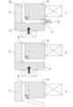
- FIG. 6(a) is a schematic diagram illustrating the state after the second step of clamping the top plate portion of intermediate material 130 between a first holding member 51 (die) arranged on the outside of the top plate portion of intermediate material 130 and a second holding member 52 (pad) arranged on the inside of the top plate portion of intermediate material 130 is completed.
- first holding member 51 die
- second holding member 52 pad
- the third step is started, and as shown in FIG. 6B, the first pressing member 61 (e.g., a pad) pushes the side wall of the intermediate material 130 back until the flange angle ⁇ f coincides with the first angle ⁇ 1 (see the black arrow) to bring the intermediate material 130 into the second state.
- the second pressing member 62 e.g., a punch
- the first pressing member 61 and the second pressing member 62 may be driven mechanically by a cam mechanism or the like, or may be driven by an actuator or the like.
- the side wall portion of the intermediate material which was in the first state, can be put into the second state, and the third step can be carried out in which the first end portion, which is the end portion on the tip side of the side wall portion of the intermediate material, is pressed toward the base end while maintaining the second state, but the above is merely one example of a means for carrying out the third step.
- step S30 By carrying out the third step (step S30) as described above, the stress history that the material 100 received in the first step (step S10) is overwritten, and the residual stress that causes the springback described above is cancelled. As a result, the possibility that the side wall portion 132 will open due to springback when the intermediate material 130 is removed from the mold after the completion of the third step is eliminated or reduced. That is, a product 200 having a top plate portion 210 and a side wall portion 220 erected at a predetermined angle ⁇ 1 (not shown in FIG. 1) from the end of the top plate portion 210 as illustrated in FIG. 1 can be integrally formed from the plate-shaped material 100 by pressing at room temperature.
- the first end E1 which is the tip end of the side wall portion 132 of the intermediate material 130, is pressed toward the base end side (bent portion side).
- stress in the elongation direction remains in the side wall portion 132, so when the intermediate material 130 is removed from the mold after the third step is completed, the side wall portion 132 is slightly elongated due to springback caused by the residual stress (see, for example, the hatched portion in (e) of FIG. 4). From the viewpoint of achieving high dimensional accuracy in the product 200, it is considered to perform the "edge cutting process" described at the beginning of this specification as an additional process.
- the pressing force and pressing amount of the first end E1 in the third step according to, for example, the material constituting the blank 100, the plate thickness of the blank 100, and the length of the side wall 220 in the product 200, so that the length of the side wall 132 after extension due to springback satisfies the dimensional accuracy required for the side wall 220 in the product 200.
- the side wall of the intermediate material is pushed back until the flange angle, which is the angle between the top plate and the side wall, becomes larger than the desired first angle due to springback, and the tip end of the side wall is pressed toward the base end while maintaining the side wall in a pushed-back state until the flange angle becomes the first angle.
- the first method in a manufacturing method in which a product having a top plate portion and a side wall portion (flange portion) erected at a predetermined angle (for example, approximately a right angle) from the end of the top plate portion is integrally formed from a plate-shaped material made of a general material by press working at room temperature, springback can be eliminated or reduced without performing the aforementioned overhang forming process as an additional process.
- Second Embodiment a method for forming a sidewall portion according to a second embodiment of the present invention (hereinafter, may be referred to as a "second method") will be described with reference to the drawings.
- the specific means for pushing back the side wall portion of the intermediate material, which is in the first state due to the side wall portion opening due to spring back, to the second state while pressing the tip end (first end) of the side wall portion of the intermediate material toward the base end is not particularly limited.
- the means illustrated in FIG. 6 is one example of a means for performing the third step.
- the means illustrated in FIG. 6 requires a first pressing member 61 and a drive device (not shown) for driving the first pressing member 61 to push back the side wall portion of the intermediate material 130 until the flange angle ⁇ f matches the first angle ⁇ 1 (see the solid black arrow) to bring the intermediate material 130 into the second state, as well as a second pressing member 62 and a drive device (not shown) for driving the second pressing member 62 to press the tip end (first end E1) of the side wall portion of the intermediate material 130 toward the base end while maintaining the second state (see the hatched arrow).
- the second method is the above-mentioned first method, which is a method for forming a side wall portion, characterized in that the third step is performed by advancing a punch having a predetermined shape in a first direction, which is a predetermined direction, relative to the intermediate material.
- the third step performed in the second method will be described in detail with reference to FIG. 7.
- FIG. 7 is a schematic diagram illustrating how the third step is performed in the second method by advancing a punch having a predetermined shape in a first direction, which is a predetermined direction, relative to the intermediate material.
- the first direction is a direction parallel to the direction from the tip end to the base end of the side wall portion of the intermediate material in the second state described above.
- the first direction is indicated by an upward-facing arrow D1 hatched with diagonal lines (hereinafter, this may be referred to as the "first direction D1").
- the punch 70 used in the second method has a first surface 71, a second surface 72, and a third surface 73 on the side surface facing the side wall portion 132 of the intermediate material 130 in the second state.
- the first surface 71 is formed at the end of the tip side of the punch 70 (the downstream side in the first direction D1, i.e., the upper side in the drawing) and is an inclined surface inclined at a predetermined angle ⁇ s with respect to the first direction D1 (see FIG. 7(b)). As illustrated in FIG. 7, the first surface 71 is inclined so that the distance from the intermediate material 130 (side wall portion 132) in the direction perpendicular to the first direction D1 decreases as the first surface 71 progresses from the tip side to the base end side of the punch 70 (the upstream side in the first direction D1, i.e., the lower side in the drawing).
- the second surface 72 is adjacent to the base end side of the first surface 71 and has a shape corresponding to the outer surface of the side wall portion 132 of the intermediate material 130 in the second state.
- the outer surface of the side wall portion 132 of the intermediate material 130 in the second state is a plane extending perpendicular to the top plate portion 131. Therefore, the second surface 72 of the punch 70, which has a shape corresponding to the outer surface of the side wall portion 132 of the intermediate material 130 in the second state, is also a plane extending perpendicular to the top plate portion 131 and faces the outer surface of the side wall portion 132 of the intermediate material 130 in the second state.
- the third surface 73 is adjacent to the base end side of the second surface 72 and has a shape that can abut against the first end E1 of the intermediate material 130 in the second state.
- the third surface 73 is formed as a plane that extends perpendicularly from the second surface 72, and forms a step having a height that corresponds to the thickness of the first end E1 of the intermediate material 130.
- the punch 70 having the above-described configuration is advanced in the first direction D1 relative to the intermediate material 130, and the processes listed below are executed in sequence.
- the punch 70 is advanced in the first direction D1 relative to the intermediate material 130 fixed in a predetermined position by clamping the top plate portion 131 between the first holding member 51 (die) and the second holding member 52 (pad).
- the punch 70 advances in the first direction D1 relative to the intermediate material 130.
- the intermediate material 130 with the top plate portion 131 clamped between the first holding member 51 and the second holding member 52 may be advanced in the opposite direction to the first direction D1 relative to the punch 70 fixed in a predetermined position.
- the first end E1 is brought into contact with the first surface 71 of the punch 70.
- the first end E1 is slid on the first surface 71, so that the side wall 132 of the intermediate material 130 begins to be accommodated from the first end E1 in the space between the second surface 72 of the punch 70 and the second holding member 52 (e.g., a pad).
- the flange angle ⁇ f coincides with the desired first angle ⁇ 1, and the second state is achieved.
- the second surface 72 is slid on the outer surface of the side wall 132 of the intermediate material 130, so that the first end E1 is brought into contact with the third surface 73 while maintaining the second state.
- the first end is pressed toward the base end by the third surface 73 of E1.
- step S10 As a result of executing the third step by advancing the punch 70 in the first direction D1 as described above, the stress history that the material 100 was subjected to in the first step (step S10) is overwritten, and as illustrated in FIG. 7(c), the stress in the contraction direction on the outside of the bent portion of the intermediate material 130 (solid black arrow) and the stress in the expansion direction on the inside (open arrow) are eliminated or reduced.
- the third step is performed by advancing a punch having a predetermined shape in the first direction, which is a predetermined direction, relative to the intermediate material. That is, in the second method, the third step can be performed with a simpler configuration without the need to drive many components in a complex manner, as illustrated in Fig. 6. Therefore, according to the second method, it is possible to eliminate or reduce springback of the intermediate material in a method of forming a product having an integrally formed top plate portion and side wall portion from a plate-shaped material made of a general material by press working at room temperature, while suppressing the increase in required labor, components, and costs.
- the side wall portion of the intermediate material opens due to springback, causing the flange angle, which is the angle between the top plate portion and the side wall portion, to become larger than the desired first angle.
- the side wall portion of the intermediate material is pushed back until the flange angle becomes the first angle, while maintaining this state. This eliminates or reduces the residual stress that causes springback in the intermediate material, and makes it possible to form a product whose flange angle matches the desired first angle.
- the third method is the above-mentioned second method, which is a method for forming a side wall portion, characterized in that in the third step, a portion of the side wall portion of the intermediate material including at least the first end portion is pressed toward the base end while being contained inside the closed space.
- the specific configuration of the closed space is not particularly limited, so long as it is possible to eliminate or reduce the residual stress that causes springback in the intermediate material by pressing the first end toward the base end, and to improve the dimensional accuracy of the shape of the side wall of the product formed by the third method.
- FIG. 8 is a schematic diagram illustrating a state in which at least a portion of the side wall of the intermediate material including the first end is pressed toward the base end in a state in which the portion is housed inside a closed space in the third step included in the third method.
- FIG. 8 is similar to FIG.
- the first end is pressed toward the base end side with at least the portion of the side wall of the intermediate material including the first end contained inside the closed space, similar to the above.
- a closed space is defined by the first holding member 51 and the second holding member 52 and the second surface 72 and the third surface 73 of the punch 70, and the first end E1 is pressed toward the base end side by the third surface 73 with the side wall of the intermediate material 130 contained inside the closed space.
- the first end is pressed toward the base end while at least a portion including the first end of the side wall of the intermediate material is housed inside the closed space. Therefore, according to the third method, it is possible to eliminate or reduce springback of the intermediate material in a method of forming a product having an integrally formed top plate and side wall from a plate-shaped material made of a general material by press working at room temperature while further improving the dimensional accuracy of the shape of the side wall of the formed product.
- the method of forming a side wall portion according to the present invention is not limited to application when molding a product having a flat side wall portion (flange) that rises from one linear edge of the top plate portion as described above.
- the method of the present invention can also be applied when molding a product having a curved side wall portion (flange) that rises from a curved edge of the top plate portion.
- the method of the present invention can also be applied when molding a product having a side wall portion (flange) that rises around the entire edge of the top plate portion.
- the method of the present invention can also be applied when molding a bowl-shaped product that has a side wall portion (flange) that rises around the entire edge of a disk-shaped top plate portion.
Landscapes
- Engineering & Computer Science (AREA)
- Mechanical Engineering (AREA)
- Shaping Metal By Deep-Drawing, Or The Like (AREA)
- Bending Of Plates, Rods, And Pipes (AREA)
Priority Applications (2)
| Application Number | Priority Date | Filing Date | Title |
|---|---|---|---|
| US18/863,836 US20260183819A1 (en) | 2023-05-09 | 2024-03-29 | Formation method of sidewall part |
| JP2024547146A JP7602097B1 (ja) | 2023-05-09 | 2024-03-29 | 側壁部の形成方法 |
Applications Claiming Priority (2)
| Application Number | Priority Date | Filing Date | Title |
|---|---|---|---|
| JP2023-076995 | 2023-05-09 | ||
| JP2023076995 | 2023-05-09 |
Publications (1)
| Publication Number | Publication Date |
|---|---|
| WO2024232182A1 true WO2024232182A1 (ja) | 2024-11-14 |
Family
ID=93429985
Family Applications (1)
| Application Number | Title | Priority Date | Filing Date |
|---|---|---|---|
| PCT/JP2024/013044 Ceased WO2024232182A1 (ja) | 2023-05-09 | 2024-03-29 | 側壁部の形成方法 |
Country Status (3)
| Country | Link |
|---|---|
| US (1) | US20260183819A1 (cg-RX-API-DMAC7.html) |
| JP (1) | JP7602097B1 (cg-RX-API-DMAC7.html) |
| WO (1) | WO2024232182A1 (cg-RX-API-DMAC7.html) |
Citations (5)
| Publication number | Priority date | Publication date | Assignee | Title |
|---|---|---|---|---|
| JPH07124657A (ja) * | 1993-11-09 | 1995-05-16 | Yutaka Giken Co Ltd | ボス部の増肉成形方法及び成形装置 |
| JPH08309469A (ja) * | 1995-05-16 | 1996-11-26 | Yamakawa Ind Co Ltd | 部品の成形方法 |
| WO2014065290A1 (ja) * | 2012-10-23 | 2014-05-01 | 新日鐵住金株式会社 | プレス加工方法及び底付容器 |
| WO2014109240A1 (ja) * | 2013-01-09 | 2014-07-17 | 新日鐵住金株式会社 | プレス成形方法 |
| JP2018164919A (ja) * | 2017-03-28 | 2018-10-25 | Jfeスチール株式会社 | プレス成形装置及びプレス成形品の製造方法 |
-
2024
- 2024-03-29 US US18/863,836 patent/US20260183819A1/en active Pending
- 2024-03-29 JP JP2024547146A patent/JP7602097B1/ja active Active
- 2024-03-29 WO PCT/JP2024/013044 patent/WO2024232182A1/ja not_active Ceased
Patent Citations (5)
| Publication number | Priority date | Publication date | Assignee | Title |
|---|---|---|---|---|
| JPH07124657A (ja) * | 1993-11-09 | 1995-05-16 | Yutaka Giken Co Ltd | ボス部の増肉成形方法及び成形装置 |
| JPH08309469A (ja) * | 1995-05-16 | 1996-11-26 | Yamakawa Ind Co Ltd | 部品の成形方法 |
| WO2014065290A1 (ja) * | 2012-10-23 | 2014-05-01 | 新日鐵住金株式会社 | プレス加工方法及び底付容器 |
| WO2014109240A1 (ja) * | 2013-01-09 | 2014-07-17 | 新日鐵住金株式会社 | プレス成形方法 |
| JP2018164919A (ja) * | 2017-03-28 | 2018-10-25 | Jfeスチール株式会社 | プレス成形装置及びプレス成形品の製造方法 |
Also Published As
| Publication number | Publication date |
|---|---|
| US20260183819A1 (en) | 2026-07-02 |
| JPWO2024232182A1 (cg-RX-API-DMAC7.html) | 2024-11-14 |
| JP7602097B1 (ja) | 2024-12-17 |
Similar Documents
| Publication | Publication Date | Title |
|---|---|---|
| JP2008055511A (ja) | ブランクから自動車用の金属薄板部材を製造する方法 | |
| KR101585439B1 (ko) | 차량용 테일게이트 인너패널의 제조방법 | |
| JP2020001055A (ja) | プレス成形品の製造方法 | |
| JP6171570B2 (ja) | 有底缶の製造方法 | |
| CN107666974B (zh) | 半开口式冲压件的成型 | |
| JP7602097B1 (ja) | 側壁部の形成方法 | |
| EP3085468A1 (en) | Press molding method and method for manufacturing press molded part | |
| JP7246349B2 (ja) | プレス成形方法及びプレス成形金型 | |
| JP2008284576A (ja) | 高張力鋼板のプレス成形加工方法及びプレス加工設備 | |
| JP4483578B2 (ja) | 枠体の製造方法 | |
| JP7454433B2 (ja) | ハット形状成形部品の製造方法、および金型 | |
| JP3497373B2 (ja) | ロッカーアーム及びその製造方法 | |
| JP4198675B2 (ja) | 複合成形品及びその製造方法 | |
| JP2000051958A (ja) | ヘミング加工方法 | |
| CN101448588A (zh) | 钢管的扩管成型方法以及钢管的扩管成型装置 | |
| JP7539307B2 (ja) | プレス部品の製造方法 | |
| JP2005186113A (ja) | 金属板のプレス成形方法 | |
| RU193520U1 (ru) | Установка для изготовления штамповкой изделия типа скрепа для бандажных систем | |
| JPWO2024232182A5 (cg-RX-API-DMAC7.html) | ||
| JP7060233B2 (ja) | プレス成形品の成形方法 | |
| WO2014175390A1 (ja) | プレス加工方法及び成形装置 | |
| JPH1190534A (ja) | 形状凍結性に優れた弓形プレス成形品の成形方法 | |
| JP2012250261A (ja) | ドア補強部材の製造方法及びドア補強部材 | |
| GB2467178A (en) | Forming a step in a sheet metal workpiece thereby reducing springback | |
| JP7317699B2 (ja) | プレス型 |
Legal Events
| Date | Code | Title | Description |
|---|---|---|---|
| WWE | Wipo information: entry into national phase |
Ref document number: 2024547146 Country of ref document: JP |
|
| WWE | Wipo information: entry into national phase |
Ref document number: 18863836 Country of ref document: US |
|
| 121 | Ep: the epo has been informed by wipo that ep was designated in this application |
Ref document number: 24803297 Country of ref document: EP Kind code of ref document: A1 |
|
| NENP | Non-entry into the national phase |
Ref country code: DE |
|
| 122 | Ep: pct application non-entry in european phase |
Ref document number: 24803297 Country of ref document: EP Kind code of ref document: A1 |
|
| WWP | Wipo information: published in national office |
Ref document number: 18863836 Country of ref document: US |