WO2024232174A1 - 模型玩具、及び可動構造体 - Google Patents
模型玩具、及び可動構造体 Download PDFInfo
- Publication number
- WO2024232174A1 WO2024232174A1 PCT/JP2024/011814 JP2024011814W WO2024232174A1 WO 2024232174 A1 WO2024232174 A1 WO 2024232174A1 JP 2024011814 W JP2024011814 W JP 2024011814W WO 2024232174 A1 WO2024232174 A1 WO 2024232174A1
- Authority
- WO
- WIPO (PCT)
- Prior art keywords
- movable
- parts
- model toy
- connecting portion
- movable mechanism
- Prior art date
- Legal status (The legal status is an assumption and is not a legal conclusion. Google has not performed a legal analysis and makes no representation as to the accuracy of the status listed.)
- Ceased
Links
Images

Classifications
-
- A—HUMAN NECESSITIES
- A63—SPORTS; GAMES; AMUSEMENTS
- A63H—TOYS, e.g. TOPS, DOLLS, HOOPS OR BUILDING BLOCKS
- A63H3/00—Dolls
-
- A—HUMAN NECESSITIES
- A63—SPORTS; GAMES; AMUSEMENTS
- A63H—TOYS, e.g. TOPS, DOLLS, HOOPS OR BUILDING BLOCKS
- A63H3/00—Dolls
- A63H3/36—Details; Accessories
- A63H3/46—Connections for limbs
Definitions
- the present invention relates to model toys and movable structures.
- Doll toys (model toys) are required to be able to move naturally and have a wide variety of poses. Therefore, to realize movements and poses similar to those of humans and animals, doll toys include various joints and movable parts.
- Patent Document 1 proposes a four-legged animal doll that has a joint structure that allows realistic movements similar to those of real animals.
- the present invention provides a novel mechanism for realizing a moving mechanism that performs movements with a natural appearance.
- the present invention is, for example, a model toy comprising a first part that serves as the base of multiple movable shafts having a spherical first connecting portion and a second connecting portion formed at one end, a second part that has a first connection portion that rotatably receives the first connecting portion, and a third part that has a second connection portion at one end that is rotatably connected to the second connecting portion, wherein a first movable mechanism of the model toy is formed by the first connecting portion and the first connection portion, and a second movable mechanism of the model toy that includes a movable shaft different from the first movable mechanism is formed by the second connecting portion and the second connection portion.
- the present invention also provides, for example, a movable structure comprising a first part that serves as a base for a plurality of movable shafts having a spherical first connecting portion and a second connecting portion formed at one end, a second part that has a first connection portion that rotatably receives the first connecting portion, and a third part that has a second connection portion at one end that is rotatably connected to the second connecting portion, wherein the first connecting portion and the first connection portion form a first movable mechanism of the movable structure, and the second connecting portion and the second connection portion form a second movable mechanism of the movable structure that includes a movable shaft different from the first movable mechanism.
- the present invention provides a novel mechanism that realizes a movable mechanism that operates in a natural way.
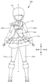
- FIG. 1 is a diagram showing an example of a front appearance of a doll-type toy according to an embodiment.
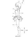
- FIG. 1 is a diagram showing an example of an exterior side view of a doll-type toy according to an embodiment.
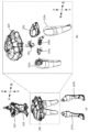
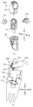
- 1A is an exploded perspective view of a torso portion of a doll-type toy according to one embodiment
- FIG. 1B is an exploded perspective view of a waist portion of the doll-type toy according to one embodiment.
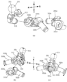
- FIG. 11 is an assembly diagram of a second movable mechanism of the doll-type toy according to one embodiment.
- 1A is an exploded view of a first movable mechanism of a doll-type toy according to one embodiment
- FIG. 1B is a plan view of the first movable mechanism
- FIG. 2 is an exploded perspective view of a leg of the doll-type toy according to one embodiment.
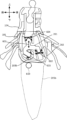
- FIG. 2 is a cross-sectional view of the body of the doll-type toy according to one embodiment.
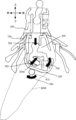
- 1A to 1C are cross-sectional views showing the operation of the lower body of a doll-type toy according to one embodiment.
- Fig. 1A shows the front appearance of the doll-type toy 100.
- Fig. 1B shows the side appearance of the doll-type toy 100. Note that the up/down, left/right, and front/back arrows indicate the orientation of the doll-type toy in the figure, and this also applies to the other figures.
- the doll toy (doll body) 100 includes a head 101, a chest 102, arms 103a, 103b, an abdomen 104, a waist 105, and legs 107a, 107b.
- the doll toy 100 is a movable doll toy such as a movable figure, and each part can be moved within a limited range caused by its relationship with other members.
- the head 101 is connected to the chest 102 by a spherical connecting member (hereinafter, also referred to as a ball joint).
- the chest 102 is further connected to arms 103 including a right arm 103a and a left arm 103b by a spherical connecting member, and is connected to the abdomen 104 at the bottom.
- the detailed structure of the chest will be described later.
- the waist 105 is connected to the abdomen 104.
- the legs 107 including the right leg 107a and the left leg 107b are connected to the waist 105, and are covered with clothing such as a skirt.
- the upper body including the head 101, chest 102, and arms 103 is referred to as the upper body.
- the lower body including the waist 105 and legs 107a, 107b is referred to as the lower body.
- the upper body and lower body are connected via the abdomen 104.
- the chest 102, abdomen 104, and waist 105 are also collectively referred to as the torso.
- the structures of the waist joint and hip joint are mainly described as the movable structure according to this embodiment. However, this is not intended to limit the present invention, and the movable structure described below is not limited to the waist joint and hip joint, but can also be applied to other joints, such as shoulder joints and chest joints that connect arms.
- FIG. 2(a) is an exploded perspective view of the chest 102 and abdomen 104, the waist 105 and the upper leg portion of the leg 107, and the lower leg portion of the leg 107.
- Figure 2(b) is an exploded view of the waist 105, including the waist joint and hip joint, and parts of the legs 107a and 107b.
- the waist 105 is connected to the abdomen 104 by a spherical connecting portion (ball joint) of part 201 shown in FIG. 2(b).
- the waist joint according to this embodiment connects the waist 105 to the abdomen 104 rotatably by a ball joint.
- this is not intended to limit the invention, and connecting portions of other shapes may be used in place of the spherical connecting portion.
- FIG. 2(b) shows the disassembled structure of the waist 105 and the upper thigh portion of the leg 107 surrounded by a dotted line in Figure 2(a).
- the waist 105 is composed of at least a plurality of parts 201 to 204.
- Part 201 is a part (first part) that serves as the base of a plurality of moving mechanisms.
- Part 202 (second part) is rotatably connected to part 201.
- Part 202 constitutes part of the waist and part of the clothing of the doll-type toy 100. Therefore, in the doll-type toy 100 according to this embodiment, part of the waist and part of the clothing move on an axis that is independent of other moving mechanisms and other parts.
- Each of the parts 203a and 203b is sequentially connected to a cylindrical portion formed at one end of the part 201. This forms the hip joint of the doll-type toy 100.
- Parts 205a and 205b which are the upper thigh portions of the legs 107a and 107b, are further connected to the parts 203a and 203, respectively.
- the parts group formed by assembling the parts 201, 202, 203a and 203b is covered with the part 204, which represents a skirt or the like that is part of the clothing of the doll-type toy 100.
- the parts 201, 202, 203a and 203b are inserted from the bottom of the part 204, and the spherical connecting portion of the part 201 is rotatably connected to the part that constitutes the abdomen 104, forming the waist joint movable mechanism.
- part 201 which serves as the base of the multiple moving mechanisms, is connected to other parts to realize the moving mechanism of part 202 (first moving mechanism), the moving mechanism of the hip joint (second moving mechanism), and the moving mechanism of the waist joint (third moving mechanism).
- first moving mechanism the moving mechanism of part 202
- second moving mechanism the moving mechanism of the hip joint
- third moving mechanism the moving mechanism of the waist joint
- this embodiment makes it possible to effectively utilize the open areas of the two openings of part 202 into which the connecting parts to the hip joints of parts 205a and 205b, which form part of legs 107a and 107b, are inserted.
- the cylindrical parts of parts 203a and 203b to which parts 205a and 205b are connected also rotate in conjunction with each other, and it is possible to obtain a movable range that makes maximum use of the open areas of the openings.
- the rotation of part 201 relative to part 204 can further expand the movable range. Therefore, more natural movements and a variety of poses can be realized. Details of the movements will be described later.
- Figures 3(a) and 3(b) show the assembled configuration of the second movable mechanism according to this embodiment.
- Figure 3(c) shows an example of the operation performed by the second movable mechanism according to this embodiment.
- part 201 includes a spherical connecting part 311 that is connected to a part of abdomen 104 to form a waist joint, a spherical connecting part 312 that is connected to part 202, and a cylindrical (or rod-shaped) connecting part 313 for forming a hip joint.
- Parts 203a and 203b also have ring-shaped connecting parts 331a and 331b at one end and cylindrical connecting parts 332a and 332b at the other end.
- one part 203b is connected to part 201.
- connecting part 313 is inserted into ring-shaped connecting part 331b and connected.
- Part 205b of leg 107b is further connected to cylindrical (or rod-shaped) connecting part 332b of part 203b.
- part 203b can rotate in the direction of the arrow with respect to part 201, with connecting part 313 as the rotation axis (movable axis). Therefore, leg 107b connected to part 203b also rotates in the direction of the arrow in conjunction with it.
- the other part 203a is further connected to part 201 to which part 203b is connected.
- cylindrical connecting part 313 is inserted into ring-shaped connecting part 331a for connection.
- Part 205a of leg 107a is further connected to cylindrical (or rod-shaped) connecting part 332a of part 203a.
- part 203b and part 203a are connected to part 201 in this order has been described, but this is not intended to limit the present invention, and they may be connected in the reverse order.
- part 203a can rotate in the direction of the arrow with respect to part 201, with connecting part 313 as the axis of rotation.
- Leg 107a connected to part 203a also rotates in the direction of the arrow in conjunction with it.
- the hip joint of doll-type toy 100 is formed by part 201 and parts 203a and 203b, and legs 107a and 107b connected to parts 203a and 203b can rotate with connecting part 313 of part 201 as the axis of rotation.
- legs 107a and 107b further include an additional movable mechanism. Details will be described later with reference to FIG. 5.
- the connecting part 313 is formed with a certain degree of inclination in the downward direction of the doll-type toy 100. This is for the purpose of realizing a movement similar to that of a human hip joint. From the hip joint of a human, the left leg and the right leg each extend in a diagonal downward direction, and do not extend straight to the side. Therefore, by forming the connecting part 313 with an inclination similar to that of a human, a movement with a more natural impression can be realized.
- the hip joint according to this embodiment can move in a diagonal downward direction. That is, the parts 203a, 203b connected to the connecting part 313 and the legs 107a, 107b connected to the parts can also rotate in a diagonal downward direction, or in a diagonal upward direction as a return direction.
- Figure 4 is a diagram illustrating the first movable mechanism according to this embodiment.
- Figure 4(a) shows how the hip joint described in Figure 3 is attached to part 202.
- Figure 4(b) shows a plan view after assembly, and
- Figure 4(c) shows a side view.
- the connecting portion 312 of part 201 is rotatably connected to the cylindrical receiving portion 401 of part 202 as a movable axis.
- Part 202 is, for example, a clothing part of doll-type toy 100, and by connecting it to part 201, it becomes able to move in accordance with the hip joint. For example, when performing an action to bend leg 107, a more natural movement can be achieved with a wider range of motion.
- Openings 402a, 402b are formed in part 202, into which legs 107a, 107b are inserted, respectively, for connection to connecting parts 332a, 332b of part 201.
- legs 107a, 107b are rotatably connected to connecting parts 332a, 332b, and can therefore move within a range corresponding to the rotational movement.
- the opening area of opening 402b formed in part 202 cannot be effectively utilized by simply rotating leg 107b around connecting part 332b as the axis of rotation.
- the connecting portion 312 of the part 201 is formed in a spherical shape and connected to the part 202.
- the part 201 can rotate in multiple directions within the range of the opening area of the openings 402a, 402b formed in the part 202. This makes it possible to effectively utilize the opening area of the openings 402a, 402b formed in the part 202, and further expand the range of movement.
- FIG. 5(a) shows an exploded view of part 205a, which is part of leg 107a.
- Figure 5(b) shows a cross-sectional view of part 203a and part 205a when connected. Note that the configuration of the right leg moving mechanism will be described using Figure 5, but the configuration of the left leg is similar and therefore will not be described.
- part 205a of leg 107a further includes parts 341 to 344.
- Part 341 is the base part of part 205a, and the spherical part 342 and the connection part 332a of part 203a are connected at the upper receiving part.
- part 342 and connection part 332a of part 203a it functions as a spherical connecting part (ball joint).
- ball joint By forming a ball joint with two parts, part 342 and part 203a, it is possible to secure the space required when assembling doll toy 100, compared to when it is realized with a single part.
- parts 203a and 342 are assembled to form a ball joint, which is provided inside leg 107a. Therefore, leg 107a, which is connected to part 205a, can rotate in all directions relative to the hip joint, as indicated by arrow 501, within the limits of the other parts.
- the cylindrical portion at the bottom of part 341 is rotatably inserted into the recess of part 344. Therefore, in leg 107a, the portion below part 344 can rotate in the direction of arrow 502 relative to part 341.
- Figure 6 shows a cross-sectional view of the torso when cut along the A-A' cut surface in Figure 1A.
- Part 201 is a connecting member that connects the abdomen 104 and waist 105, and is assembled with at least four movable mechanisms, indicated by arrows 601 to 604, together with the parts that are connected. Movement in the direction of arrow 601 indicates that part 201 can move in the vertical direction of the doll-type toy 100 from the abdomen 104, which is connected to the spherical connecting part 311. This allows part 201 and the waist 105 connected to part 201 to be shifted downward from the abdomen 104, creating a space between the abdomen 104 and waist 105. This space is intended to ensure space when moving in the directions of arrows 602 to 603, for example, and has the effect of further expanding the range of motion.
- Arrow 602 indicates that part 202 can rotate in multiple directions relative to part 201, as explained using Figure 4. This operation has already been explained, so details will be omitted.
- Arrow 603 indicates that parts 203a and 203b can rotate in the up and down directions of doll toy 100 relative to part 201, as explained using Figure 4. This operation has already been explained, so details will be omitted.
- Arrow 604 indicates that part 201 can rotate in all directions relative to abdomen 104 within the spatial limitations imposed by other parts. This is because connecting portion 311 of part 201 is formed in a spherical shape. In this way, the movable mechanism centered on part 201 according to this embodiment is capable of at least the four movements described above. By combining these four movements, doll-type toy 100 according to this embodiment can achieve a variety of movements with a wider range of motion using fewer parts.
- Figure 7 shows the posture when the leg 107 (part 205b of leg 107b) is rotated forward.
- part 201 is pulled out downward. This causes the various parts of waist 105 and leg 107 connected to part 201 to be pulled out downward at the same time.
- parts 203a and 203b can each be rotated diagonally downward (for example, 18 degrees) relative to connecting part 313 of part 201.
- legs 107a and 107b also move in a direction away from the upper body of doll-type toy 100. Therefore, a gap is created between legs 107 and the upper body around the buttocks of doll-type toy 100, which breaks the lines of the doll-type toy 100's body shape and gives an unnatural impression.
- part 202 can be rotated downward (for example, 20 degrees) relative to part 201.
- part 202 forms part of the waist and part of the clothing, it can move in accordance with the movement of leg 107, making the body lines appear smoother.
- the ball joint (610) formed by parts 205 and 203 allows the leg 107 to rotate within the spatial range of the clothing part. By operating in this manner, the leg 107 can be rotated greatly in the forward direction. Note that the order of the above-mentioned operations is not intended to limit the present invention, and the operations can be performed in any order.
- the model toy (100) includes a first part (201) that serves as the base of multiple movable shafts having a spherical first connecting part (312) and a second connecting part (313) formed at one end, a second part (202) that has a first connection part (401) that rotatably receives the first connecting part, and a third part (203a, 203b) that has a second connection part (331a, 331b) at one end that is rotatably connected to the second connecting part.
- first connecting part and the first connection part form a first movable mechanism of the model toy
- second connecting part and the second connection part form a second movable mechanism of the model toy that includes a movable shaft different from the first movable mechanism.
- the present invention can provide a mechanism for realizing multiple movable mechanisms with fewer parts, for example in a model toy.
- the present invention allows the legs 107a, 107b connected to the hip joints to rotate in multiple directions by the first and second moving mechanisms, and makes effective use of the opening areas of the openings 402a, 402b of the parts 202. This provides a mechanism for realizing a moving mechanism that performs movements with a natural impression.
- a doll-type toy was described as an example of a model toy, but the shape of the doll-type toy (doll body) is not particularly limited, and may include a variety of shapes such as people, animals, robots, insects, dinosaurs, and imaginary life forms.
- the shape of the model toy is not particularly limited as long as it includes movable parts.
- a model toy comprising: a first part serving as a base for a plurality of movable shafts, each having a spherical first coupling part and a second coupling part formed at one end; a second part having a first connection part for rotatably receiving the first coupling part; and a third part having a second connection part at one end rotatably connected to the second coupling part, wherein a first movable mechanism of the model toy is formed by the first coupling part and the first connection part, and a second movable mechanism of the model toy including a movable shaft different from the first movable mechanism is formed by the second coupling part and the second connection part.
- the model toy described in (3) characterized in that the first moving mechanism functions as a moving axis of the second part forming a part of the clothing of the model toy, the second moving mechanism functions as a moving axis of a hip joint of the model toy, and the third moving mechanism functions as a moving axis of a waist joint of the model toy.
- the model toy described in (2) characterized in that legs of the model toy are respectively connected to the other ends of the two third parts.
- a movable structure comprising: a first part serving as a base for a plurality of movable shafts having a spherical first connecting part and a second connecting part formed at one end; and a first connecting part that rotatably receives the first connecting part.
- a movable structure comprising: a second part having a connecting portion; and a third part having at one end a second connecting portion rotatably connected to the second connecting portion, wherein a first movable mechanism of the movable structure is formed by the first connecting portion and the first connecting portion, and a second movable mechanism of the movable structure including a movable axis different from the first movable mechanism is formed by the second connecting portion and the second connecting portion.
- 100 Doll type toy, 101: Head, 102: Chest, 103a, 103b: Arms, 104: Abdomen, 105: Waist, 107a, 107b: Legs
Landscapes
- Toys (AREA)
Abstract
【課題】本発明は、例えば自然な印象で動作を行う可動機構を実現する仕組みを提供する。【解決手段】本人形型玩具(100)は、球形状の第1連結部(312)と、一端に形成された第2連結部(313)とを有する複数の可動軸の基部となる第1パーツ(201)と、第1連結部を回動可能に受け入れる第1接続部(401)を有する第2パーツ(202)と、第2連結部に回転可能に接続される第2接続部(331a、331b)を一端に有する第3パーツ(203a、203b)とを備える。また、第1連結部と第1接続部によって模型玩具の第1可動機構が形成され、第2連結部と第2接続部によって、第1可動機構とは異なる可動軸を含む模型玩具の第2可動機構が形成される。
Description
本発明は、模型玩具、及び可動構造体に関する。
人形型玩具(模型玩具)においては、自然な動作や多彩なポージングを実現することが求められている。したがって、人間や動物に近い動作やポージングを実現すべく、人形型玩具には種々の関節や可動部が含まれるものである。特許文献1には、現実の動物と同様なリアルな動きを可能とした関節構造を有している四足動物人形が提案されている。
上記従来技術では、多彩な動作を実現するために種々の関節が含まれ、各関節は複数のパーツから構成されている。しかし、小型の人形型玩具においては、その空間的な制限からできる限り少ない数のパーツで多彩な動作を行うことが求められる。
本発明は、自然な印象で動作を行う可動機構を実現する新規な仕組みを提供する。
本発明は、例えば、模型玩具であって、球形状の第1連結部と、一端に形成された第2連結部とを有する複数の可動軸の基部となる第1パーツと、前記第1連結部を回動可能に受け入れる第1接続部を有する第2パーツと、前記第2連結部に回転可能に接続される第2接続部を一端に有する第3パーツとを備え、前記第1連結部と前記第1接続部によって前記模型玩具の第1可動機構が形成され、前記第2連結部と前記第2接続部によって、前記第1可動機構とは異なる可動軸を含む前記模型玩具の第2可動機構が形成されることを特徴とする。
また、本発明は、例えば、可動構造体であって、球形状の第1連結部と、一端に形成された第2連結部とを有する複数の可動軸の基部となる第1パーツと、前記第1連結部を回動可能に受け入れる第1接続部を有する第2パーツと、前記第2連結部に回転可能に接続される第2接続部を一端に有する第3パーツとを備え、前記第1連結部と前記第1接続部によって前記可動構造体の第1可動機構が形成され、前記第2連結部と前記第2接続部によって、前記第1可動機構とは異なる可動軸を含む前記可動構造体の第2可動機構が形成されることを特徴とする。
本発明によれば、自然な印象で動作を行う可動機構を実現する新規な仕組みを提供することができる。
以下、添付図面を参照して実施形態を詳しく説明する。尚、以下の実施形態は特許請求の範囲に係る発明を限定するものではなく、また実施形態で説明されている特徴の組み合わせの全てが発明に必須のものとは限らない。実施形態で説明されている複数の特徴うち二つ以上の特徴が任意に組み合わされてもよい。また、同一若しくは同様の構成には同一の参照番号を付し、重複した説明は省略する。
<人形型玩具の外観> まず、図1A及び図1Bを参照して、本実施形態に係る人形型玩具100の外観構成の一例について説明する。図1Aは人形型玩具100の外観正面を示す。図1Bは人形型玩具100の外観側面を示す。なお、上下、左右、前後の矢印については図における人形型玩具の向きを示し、他の図面についても同様である。
人形型玩具(人形体)100は、頭部101、胸部102、腕部103a、103b、腹部104、腰部105、及び脚部107a、107bを備える。人形型玩具100は、可動フィギアなどの可動式の人形型玩具であり、各パーツは他の部材との関係で生じる制限領域の範囲内で可動させることができる。頭部101は胸部102に球形状の連結部材によって連結される(以下では、ボールジョイントとも称する。)。胸部102には、さらに右腕部103a及び左腕部103bを含む腕部103が球形状の連結部材で連結され、下部において腹部104が連結される。胸部の詳細な構成については後述する。腹部104には腰部105が連結される。腰部105には右脚部107a及び左脚部107bを含む脚部107が連結され、スカート等の服飾部で覆われる。
なお、以下では、頭部101、胸部102、及び腕部103を含む上半身を上体部と称する。また、腰部105、脚部107a、107bを含む下半身を下体部と称する。上体部及び下体部は腹部104を介して連結される。また、胸部102、腹部104、及び腰部105をまとめて胴体部とも称する。以下では、本実施形態に係る可動構造体として、主に腰関節及び股関節の構造について説明する。しかしながら、本発明を限定する意図はなく、以下で説明する可動構造体は、腰関節や股関節に限らず、他の関節部、例えば腕部を連結する肩関節や胸関節などの関節部に適用することも可能である。
<腰部の構成> 次に、図2を参照して、本実施形態に係る人形型玩具100の腰部105を中心とした付近の詳細構成ついて説明する。図2(a)は胸部102及び腹部104と、腰部105及び脚部107の上腿部分と、脚部107の下腿部分とを分解した斜視図である。図2(b)は腰関節及び股関節を含む腰部105と、脚部107a、107bの一部との分解図である。
図2(a)に示すように、腰部105は腹部104に対して連結されるものであり、図2(b)に示すパーツ201の球形状の連結部(ボールジョイント)で連結される。即ち、本実施形態に係る腰関節はボールジョイントで回動可能に腰部105を腹部104に対して連結するものである。しかし、本発明を限定する意図はなく、球形状の連結部に代えて他の形状の連結部を採用してもよい。
図2(b)は図2(a)の点線で囲まれた腰部105及び脚部107の上腿部分の分解構成を示す。腰部105は、少なくとも複数のパーツ201~204を含んで構成される。パーツ201は、複数の可動機構の基部となるパーツ(第1パーツ)である。パーツ202(第2パーツ)はパーツ201に対して回動可能に接続される。パーツ202は、人形型玩具100の腰部の一部や服飾の一部を構成する。したがって、本実施形態に係る人形型玩具100では、腰部の一部や服飾の一部が他可動機構や他のパーツから独立した軸可動で動作するものである。
パーツ203a、203bのそれぞれは、パーツ201の一端に形成された円筒部に順次接続される。これにより、人形型玩具100の股関節が形成される。パーツ203a、203のそれぞれには、さらに、脚部107a、107bの上腿部分であるパーツ205a、205bが接続される。また、パーツ201、202、203a、203bが組み立てられたパーツ群が、人形型玩具100の服飾の一部であるスカート等を表現するパーツ204で覆われる。具体的には、パーツ201、202、203a、203bがパーツ204の下部から挿入され、パーツ201の球形状の連結部が腹部104を構成するパーツに回動可能に連結され、腰関節可動機構が構成される。
このように、複数可動機構の基部となるパーツ201が他のパーツと連結されることによって、パーツ202の可動機構(第1可動機構)、股関節の可動機構(第2可動機構)、及び腰関節の可動機構(第3可動機構)が実現される。これにより、少ないパーツで種々の動作を実現することができる。具体的には、パーツ201がボールジョイントによってパーツ202に対して多方向に回動可能に接続される。
複数の可動機構を実現することによって、本実施形態によれば、脚部107a、107bの一部を形成するパーツ205a、205bの股関節への接続部分がそれぞれ挿入されるパーツ202の2つの開口部の開口領域を有効に利用することができる。例えば、パーツ201がパーツ202に対して多方向に回動することにより、パーツ205a、205bがそれぞれ接続されるパーツ203a、203bの円筒部も連動して回動し、当該開口部の開口領域を最大限に活用した可動範囲を得ることができる。つまり、股関節の可動機構による可動に加えて、パーツ201によるパーツ204に対する回動により、さらに可動範囲を広げることができる。従って、より自然な動作や多彩なポージングを実現することができる。動作の詳細については後述する。
<複数の可動機構の詳細な構成> 次に、図3及び図4を参照して、本実施形態に係る人形型玩具100の複数の可動機構の詳細構成について説明する。図3(a)及び図3(b)は本実施形態に係る第2可動機構の組立構成を示す。図3(c)は本実施形態に係る第2可動機構による動作の一例を示す。
図3(a)に示すように、パーツ201には、腹部104のパーツに連結され、腰関節を形成する球形状の連結部311と、パーツ202に連結される球形状の連結部312と、股関節を形成するための円筒形状(又は棒形状)の連結部313とが含まれる。また、パーツ203a、203bは、一端にリング形状の接続部331a、331bと、他端に円筒形状の接続部332a、332bとを有する。まずパーツ201には一方のパーツ203bが接続される。具体的には、リング形状の接続部331bに対して連結部313が挿入されて連結される。パーツ203bの円筒形状(又は棒形状)の接続部332bにはさらに脚部107bのパーツ205bが接続される。
図3(b)に示すように、パーツ203bはパーツ201に対して連結部313を回転軸(可動軸)として矢印方向に回転可能である。したがって、パーツ203bに接続される脚部107bも連動して矢印方向に回動する。パーツ203bが接続されたパーツ201には、さらに他方のパーツ203aが接続される。具体的には、リング形状の接続部331aに対して円筒形状の連結部313が挿入されて連結される。パーツ203aの円筒形状(又は棒形状)の接続部332aにはさらに脚部107aのパーツ205aが接続される。ここでは、パーツ201に対してパーツ203b、パーツ203aの順序で連結する例について説明したが、本発明を限定する意図はなく、逆の順序で連結されてもよい。
図3(c)に示すように、パーツ203aはパーツ201に対して連結部313を回転軸として矢印方向に回転可能である。パーツ203aに接続される脚部107aも連動して矢印方向に回動する。このように、本実施形態に係る人形型玩具100の股関節はパーツ201とパーツ203a、203bとによって形成され、パーツ203a、203bに連結される脚部107a、107bがパーツ201の連結部313を回転軸として回動することができる。なお、脚部107a、107bはさらに追加の可動機構を備える。詳細については図5を用いて後述する。
また、図3(c)を参照すると明らかなように、連結部313は人形型玩具100の下方向にある程度の傾きを有して形成される。これは、人間の股関節に類似した動作を実現するためのものである。人間の股関節からは、左脚、右脚がそれぞれ斜め下方向に延伸しており、真横に延伸しているわけではない。したがって、連結部313を人間と同様の傾きで形成することにより、より自然な印象での動作を実現することができる。例えば、本実施形態に係る股関節は斜め下方向に動作することができる。即ち、連結部313に接続されるパーツ203a、203b及び当該
パーツに接続される脚部107a、107bについても斜め下方向、或いは戻る方向として斜め上方向への回動が可能となる。
パーツに接続される脚部107a、107bについても斜め下方向、或いは戻る方向として斜め上方向への回動が可能となる。
図4は本実施形態に係る第1可動機構を説明する図である。図4(a)は図3で説明した股関節をパーツ202へ組み付ける様子を示す。図4(b)は組立後の平面図を示し、図4(c)は側面図を示す。
図4(a)に示すように、股関節として組み立てられたパーツ群のうち、パーツ201の連結部312が可動軸としてパーツ202の円筒形状の受け入れ部401に回動可能に連結される。これにより第2可動機構が構成される。パーツ202は例えば人形型玩具100の服飾部であり、パーツ201と連結することにより股関節に追従して動作可能となり、例えば脚部107を屈折させる動作を行う場合に、より可動範囲を広げつつ自然な動作を実現することができる。
パーツ202には、脚部107a、107bがそれぞれ挿入されて、パーツ201の接続部332a、332bと連結させるための開口部402a、402bが形成されている。なお、パーツ201がパーツ202に対して可動しない構成である場合、脚部107a、107bは、接続部332a、332bに対して回転可能に連結されるため、当該回転動作に応じた範囲内で動作することができる。しかし、図4(c)に示すように、接続部332bを回転軸とした脚部107bの回転動作だけでは、パーツ202に形成された開口部402bの開口領域を有効に利用することができない。
そこで、本実施形態では、パーツ201の連結部312を球形状で形成し、パーツ202に対して連結させる。これにより、図4(b)及び図4(c)に示すように、パーツ201は、パーツ202に形成された開口部402a、402bの開口領域の範囲内で多方向に回動可能となる。これにより、パーツ202に形成された開口部402a、402bの開口領域を有効に利用し、より可動範囲を拡大させることができる。
<脚部の可動機構> 次に、図5を参照して、本実施形態に係る股関節に接続される脚部の可動機構ついて説明する。図5(a)は脚部107aの一部のパーツ205aの分解図を示す。図5(b)はパーツ203aとパーツ205aを接続した状態の断面図を示す。なお、図5を用いて、右脚の可動機構の構成について説明するが、左脚の構成については同様であるため説明を省略する。
図5(a)に示すように、脚部107aのパーツ205aは、さらにパーツ341~344を含んで構成される。パーツ341はパーツ205aの基部となるパーツであり、上部の受け入れ部において、球形状のパーツ342とパーツ203aの接続部332aが接続される。つまり、パーツ342とパーツ203aの接続部332aが組み付けられることにより、球形状の連結部(ボールジョイント)として機能する。なお、パーツ342とパーツ203aとの2つのパーツでボールジョイントを形成することにより、1つのパーツで実現する場合と比較して、人形型玩具100を組み立てる際に必要な空間を確保することができる。
図5(b)に示すように、パーツ203aとパーツ342とが組み付けられてボールジョイントを形成し、脚部107aの内部に設けられる。したがって、パーツ205aに接続される脚部107aは、股関節に対して他のパーツの制限の範囲内で矢印501に示すように全方向に回動可能となる。また、パーツ341の下部の円筒部がパーツ344の凹部に回転可能に挿入される。したがって、脚部107aでは、パーツ344以下の部分がパーツ341に対して矢印502の方向に回転可能である。
<下体部の動作> 以下では、図6及び図7を参照して、本実施形態に係る下体部の動作について説明する。図6は図1AのA-A’の切断面で切断した場合の胴体部の断面図を示す。
パーツ201は腹部104及び腰部105を連結する連結部材であり、接続されるパーツとともに矢印601~604の少なくとも4つの可動機構を有して組み付けられる。矢印601方向の動作は、球形状で形成された連結部311に接続される腹部104からパーツ201が人形型玩具100の上下方向への動作可能であることを示す。これにより、パーツ201及びパーツ201に接続された腰部105は、腹部104から下方向へずらすことができ、腹部104と腰部105と間に空間をつくることができる。この空間は、例えば矢印602~603方向へ動作する際の空間を確保するためのものであり、より可動域を広げる効果がある。
矢印602は、図4を用いて説明したように、パーツ201に対してパーツ202が多方向に回動可能であることを示す。当該動作については既に説明しているため詳細については省略する。矢印603は、図4を用いて説明したように、パーツ201に対してパーツ203a、203bが人形型玩具100の上下方向に回転可能であることを示す。当該動作については既に説明しているため詳細については省略する。
矢印604は、腹部104に対して他のパーツによる空間的制限の範囲内で全方向へ回動可能であることを示す。これは、パーツ201の連結部311が球形状で形成されているためである。このように、本実施形態に係るパーツ201を中心とした可動機構は上述した少なくとも4つの動作が可能である。これらの4つの動作を組み合わせることにより、本実施形態に係る人形型玩具100は少ないパーツでより広い可動域で種々の動作を実現することができる。
以下では、本実施形態に係る人形型玩具100の動作の一例を示す。図7は脚部107(脚部107bのパーツ205b)を前方向に回動させた状態での姿勢を示す。
まず矢印701に示すように、パーツ201を下方向に引き出す。これにより、パーツ201に接続された腰部105の各種パーツや脚部107も同時に下方向へ引き出される。続いて、矢印702に示すように、パーツ201の連結部313に対してパーツ203a、203bをそれぞれ斜め下方向に(例えば、18度)回動させることができる。この際、脚部107a、107bも同様に人形型玩具100の上体部から離れる方向に動作する。したがって、人形型玩具100の臀部あたりにおいて、脚部107と上体部との間に隙間が発生し、人形型玩具100の体形のラインが途切れてしまい不自然な印象となる。
そこで、本実施形態によればさらに、矢印703に示すように、パーツ201に対してパーツ202を下方向に(例えば、20度)回転させることができる。これにより、パーツ202が腰部の一部や服飾部の一部を形成しているため、脚部107の動きに追従した動作を行うことができ、体のラインを滑らかに見せることができる。
さらに、矢印704に示すように、パーツ205とパーツ203とによって形成されたボールジョイント(610)によって、脚部107を服飾パーツの空間の範囲内で回動させることができる。このように動作させることにより、脚部107を前方向に大きく回動させることができる。なお、上述した動作の順序については本発明を限定する意図はなく、任意の順序で動作することが可能である。
図7に示すように、腰部105及び脚部107bを前方向に回動させた場合において、人形型玩具100の背中から臀部にかけてのライン(点線で示す)が滑らに自然な印象で当該回動動作を行うことができる。なお、股関節が斜め方向に動作することから、脚部107a、107bをクロスさせるなどの姿勢を容易に行うことも可能である。
以上説明したように、本実施形態に係る模型玩具(100)は、球形状の第1連結部(312)と、一端に形成された第2連結部(313)とを有する複数の可動軸の基部となる第1パーツ(201)と、第1連結部を回動可能に受け入れる第1接続部(401)を有する第2パーツ(202)と、第2連結部に回転可能に接続される第2接続部(331a、331b)を一端に有する第3パーツ(203a、203b)とを備える。また、第1連結部と第1接続部によって模型玩具の第1可動機構が形成され、第2連結部と第2接続部によって、第1可動機構とは異なる可動軸を含む模型玩具の第2可動機構が形成される。これにより、本発明は、例えば模型玩具において、より少ないパーツで複数の可動機構を実現する仕組みを提供することができる。また、本発明は、例えば、第1可動機構及び第2可動機構によって、股関節に接続された脚部107a、107bが多方向に回動することができ、パーツ202の開口部402a、402bの開口領域を有効に利用することができる。これにより、自然な印象で動作を行う可動機構を実現する仕組みを提供することができる。
<変形例> 本発明は上記実施形態に制限されるものではなく、発明の要旨の範囲内で、種々の変形・変更が可能である。上記実施形態では、模型玩具として人形型玩具の例を説明したが、人形型玩具(人形体)の形状は、特に限定されるものではなく、人、動物、ロボット、昆虫、恐竜、仮想生命体等、様々な形状を含むものである。また、可動部を含む形態であれば、模型玩具の形状は特に限定されるものではない。
<実施形態のまとめ> 上記実施形態は以下の模型玩具、及び関節構造体を少なくとも開示する。(1)模型玩具であって、 球形状の第1連結部と、一端に形成された第2連結部とを有する複数の可動軸の基部となる第1パーツと、 前記第1連結部を回動可能に受け入れる第1接続部を有する第2パーツと、 前記第2連結部に回転可能に接続される第2接続部を一端に有する第3パーツとを備え、 前記第1連結部と前記第1接続部によって前記模型玩具の第1可動機構が形成され、 前記第2連結部と前記第2接続部によって、前記第1可動機構とは異なる可動軸を含む前記模型玩具の第2可動機構が形成されることを特徴とする模型玩具。(2)前記第3パーツは、それぞれが前記第2接続部を有する2つの第3パーツであり、 前記第2可動機構は、一方の前記第3パーツの第2接続部が前記第2連結部に回転可能に接続され、さらに、他方の前記第3パーツの第2接続部が該第2連結部に回転可能に接続されることにより形成されることを特徴とする(1)に記載の模型玩具。(3)前記第1パーツは他端に形成された球形状の第3連結部をさらに有し、 前記第3連結部は第4パーツと接続されて第3可動機構を形成することを特徴とする(1)又は(2)に記載の模型玩具。(4)前記第1可動機構は、前記模型玩具の服飾の一部を形成する前記第2パーツの可動軸として機能し、 前記第2可動機構は、前記模型玩具の股関節の可動軸として機能し、 前記第3可動機構は、前記模型玩具の腰関節の可動軸として機能することを特徴とする(3)に記載の模型玩具。(5)2つの前記第3パーツの他端には、前記模型玩具の脚部がそれぞれ接続されることを特徴とする(2)に記載の模型玩具。(6)2つの前記第3パーツの他端はそれぞれ円筒部を有し、 各円筒部が前記脚部の内部に設けられた球形状の接続部へ挿入され、各脚部が前記第3パーツに対して回動可能に接続されることを特徴とする(5)に記載の模型玩具。(7)前記第2パーツは、前記第1パーツに連結された際に、前記第1パーツ及び前記第3パーツを覆うように形成され、かつ、前記第3パーツの前記第2接続部に対して前記脚部を接続するための開口部が形成されており、 前記脚部は、前記第1可動機構及び前記第2可動機構によって前記開口部の開口領域の範囲内で多方向に回動可能であることを特徴とする(5)又は(6)に記載の模型玩具。(8)前記第2可動機構による前記脚部の回動に追従して、前記第1可動機構によって前記第2パーツが回動可能であることを特徴とする(5)乃至(7)の何れか1つに記載の模型玩具。(9)可動構造体であって、 球形状の第1連結部と、一端に形成された第2連結部とを有する複数の可動軸の基部となる第1パーツと、 前記第1連結部を回動可能に受け入れる第1
接続部を有する第2パーツと、 前記第2連結部に回転可能に接続される第2接続部を一端に有する第3パーツとを備え、 前記第1連結部と前記第1接続部によって前記可動構造体の第1可動機構が形成され、 前記第2連結部と前記第2接続部によって、前記第1可動機構とは異なる可動軸を含む前記可動構造体の第2可動機構が形成されることを特徴とする可動構造体。
接続部を有する第2パーツと、 前記第2連結部に回転可能に接続される第2接続部を一端に有する第3パーツとを備え、 前記第1連結部と前記第1接続部によって前記可動構造体の第1可動機構が形成され、 前記第2連結部と前記第2接続部によって、前記第1可動機構とは異なる可動軸を含む前記可動構造体の第2可動機構が形成されることを特徴とする可動構造体。
100:人形型玩具、101:頭部、102:胸部、103a、103b:腕部、104:腹部、105:腰部、107a、107b:脚部
Claims (9)
- 模型玩具であって、 球形状の第1連結部と、一端に形成された第2連結部とを有する複数の可動軸の基部となる第1パーツと、 前記第1連結部を回動可能に受け入れる第1接続部を有する第2パーツと、 前記第2連結部に回転可能に接続される第2接続部を一端に有する第3パーツとを備え、 前記第1連結部と前記第1接続部によって前記模型玩具の第1可動機構が形成され、 前記第2連結部と前記第2接続部によって、前記第1可動機構とは異なる可動軸を含む前記模型玩具の第2可動機構が形成されることを特徴とする模型玩具。
- 前記第3パーツは、それぞれが前記第2接続部を有する2つの第3パーツであり、 前記第2可動機構は、一方の前記第3パーツの第2接続部が前記第2連結部に回転可能に接続され、さらに、他方の前記第3パーツの第2接続部が該第2連結部に回転可能に接続されることにより形成されることを特徴とする請求項1に記載の模型玩具。
- 前記第1パーツは他端に形成された球形状の第3連結部をさらに有し、 前記第3連結部は第4パーツと接続されて第3可動機構を形成することを特徴とする請求項1に記載の模型玩具。
- 前記第1可動機構は、前記模型玩具の服飾の一部を形成する前記第2パーツの可動軸として機能し、 前記第2可動機構は、前記模型玩具の股関節の可動軸として機能し、 前記第3可動機構は、前記模型玩具の腰関節の可動軸として機能することを特徴とする請求項3に記載の模型玩具。
- 2つの前記第3パーツの他端には、前記模型玩具の脚部がそれぞれ接続されることを特徴とする請求項2に記載の模型玩具。
- 2つの前記第3パーツの他端はそれぞれ円筒部を有し、 各円筒部が前記脚部の内部に設けられた球形状の接続部へ挿入され、各脚部が前記第3パーツに対して回動可能に接続されることを特徴とする請求項5に記載の模型玩具。
- 前記第2パーツは、前記第1パーツに連結された際に、前記第1パーツ及び前記第3パーツを覆うように形成され、かつ、前記第3パーツの前記第2接続部に対して前記脚部を接続するための開口部が形成されており、 前記脚部は、前記第1可動機構及び前記第2可動機構によって前記開口部の開口領域の範囲内で多方向に回動可能であることを特徴とする請求項5又は6に記載の模型玩具。
- 前記第2可動機構による前記脚部の回動に追従して、前記第1可動機構によって前記第2パーツが回動可能であることを特徴とする請求項7に記載の模型玩具。
- 可動構造体であって、 球形状の第1連結部と、一端に形成された第2連結部とを有する複数の可動軸の基部となる第1パーツと、 前記第1連結部を回動可能に受け入れる第1接続部を有する第2パーツと、 前記第2連結部に回転可能に接続される第2接続部を一端に有する第3パーツとを備え、 前記第1連結部と前記第1接続部によって前記可動構造体の第1可動機構が形成され、 前記第2連結部と前記第2接続部によって、前記第1可動機構とは異なる可動軸を含む前記可動構造体の第2可動機構が形成されることを特徴とする可動構造体。
Applications Claiming Priority (2)
| Application Number | Priority Date | Filing Date | Title |
|---|---|---|---|
| JP2023077350A JP7360566B1 (ja) | 2023-05-09 | 2023-05-09 | 模型玩具、及び可動構造体 |
| JP2023-077350 | 2023-05-09 |
Publications (1)
| Publication Number | Publication Date |
|---|---|
| WO2024232174A1 true WO2024232174A1 (ja) | 2024-11-14 |
Family
ID=88242095
Family Applications (1)
| Application Number | Title | Priority Date | Filing Date |
|---|---|---|---|
| PCT/JP2024/011814 Ceased WO2024232174A1 (ja) | 2023-05-09 | 2024-03-26 | 模型玩具、及び可動構造体 |
Country Status (3)
| Country | Link |
|---|---|
| JP (2) | JP7360566B1 (ja) |
| CN (1) | CN117695678A (ja) |
| WO (1) | WO2024232174A1 (ja) |
Families Citing this family (1)
| Publication number | Priority date | Publication date | Assignee | Title |
|---|---|---|---|---|
| JP7456056B1 (ja) * | 2023-10-30 | 2024-03-26 | 株式会社バンダイ | 模型玩具、及び可動構造体 |
Citations (3)
| Publication number | Priority date | Publication date | Assignee | Title |
|---|---|---|---|---|
| JP3153501U (ja) * | 2009-06-05 | 2009-09-10 | 有限会社ダイスプロジェクト | 人形玩具における股関節及び腰関節を含む腰部の被覆構造 |
| JP2019171218A (ja) * | 2019-07-23 | 2019-10-10 | 株式会社バンダイ | 人形体の肩関節構造 |
| JP7168806B1 (ja) * | 2022-03-11 | 2022-11-09 | 株式会社バンダイ | 模型玩具、及び可動構造 |
-
2023
- 2023-05-09 JP JP2023077350A patent/JP7360566B1/ja active Active
- 2023-09-28 JP JP2023168856A patent/JP2024162961A/ja active Pending
- 2023-12-25 CN CN202311789526.8A patent/CN117695678A/zh active Pending
-
2024
- 2024-03-26 WO PCT/JP2024/011814 patent/WO2024232174A1/ja not_active Ceased
Patent Citations (3)
| Publication number | Priority date | Publication date | Assignee | Title |
|---|---|---|---|---|
| JP3153501U (ja) * | 2009-06-05 | 2009-09-10 | 有限会社ダイスプロジェクト | 人形玩具における股関節及び腰関節を含む腰部の被覆構造 |
| JP2019171218A (ja) * | 2019-07-23 | 2019-10-10 | 株式会社バンダイ | 人形体の肩関節構造 |
| JP7168806B1 (ja) * | 2022-03-11 | 2022-11-09 | 株式会社バンダイ | 模型玩具、及び可動構造 |
Also Published As
| Publication number | Publication date |
|---|---|
| CN117695678A (zh) | 2024-03-15 |
| JP2024162961A (ja) | 2024-11-21 |
| JP2024162121A (ja) | 2024-11-21 |
| JP7360566B1 (ja) | 2023-10-12 |
Similar Documents
| Publication | Publication Date | Title |
|---|---|---|
| JP7168806B1 (ja) | 模型玩具、及び可動構造 | |
| JP7079363B1 (ja) | 人形型玩具、及び関節構造 | |
| JP7670646B2 (ja) | 人形体、及び回動機構 | |
| JP7430286B1 (ja) | 模型玩具、及び関節構造体 | |
| WO2024232174A1 (ja) | 模型玩具、及び可動構造体 | |
| JP7778730B2 (ja) | 模型玩具、及び関節構造 | |
| JP7168805B1 (ja) | 模型玩具、及び可動構造 | |
| JP2026001154A (ja) | 人形体、及び関節構造 | |
| JP2025063887A (ja) | 模型玩具、及び可動構造体 | |
| JP2023166962A (ja) | 模型玩具、及び関節構造 | |
| JP2023165305A (ja) | 人形体、及び回動機構 | |
| JP7612065B1 (ja) | 模型玩具、及び可動構造体 | |
| JP7587667B1 (ja) | 模型玩具 | |
| JP7460842B1 (ja) | 模型玩具、及び可動構造体 | |
| JP7479556B1 (ja) | 模型玩具及び関節構造体 | |
| JP7752272B1 (ja) | 模型玩具、及び模型部品 | |
| WO2025094916A1 (ja) | 模型玩具、及び可動構造体 |
Legal Events
| Date | Code | Title | Description |
|---|---|---|---|
| 121 | Ep: the epo has been informed by wipo that ep was designated in this application |
Ref document number: 24803289 Country of ref document: EP Kind code of ref document: A1 |
|
| NENP | Non-entry into the national phase |
Ref country code: DE |