WO2024232153A1 - フッ素含有非晶質炭素膜、及びその製造方法 - Google Patents
フッ素含有非晶質炭素膜、及びその製造方法 Download PDFInfo
- Publication number
- WO2024232153A1 WO2024232153A1 PCT/JP2024/008463 JP2024008463W WO2024232153A1 WO 2024232153 A1 WO2024232153 A1 WO 2024232153A1 JP 2024008463 W JP2024008463 W JP 2024008463W WO 2024232153 A1 WO2024232153 A1 WO 2024232153A1
- Authority
- WO
- WIPO (PCT)
- Prior art keywords
- fluorine
- amorphous carbon
- containing amorphous
- film
- carbon film
- Prior art date
- Legal status (The legal status is an assumption and is not a legal conclusion. Google has not performed a legal analysis and makes no representation as to the accuracy of the status listed.)
- Ceased
Links
Images







Classifications
-
- C—CHEMISTRY; METALLURGY
- C03—GLASS; MINERAL OR SLAG WOOL
- C03C—CHEMICAL COMPOSITION OF GLASSES, GLAZES OR VITREOUS ENAMELS; SURFACE TREATMENT OF GLASS; SURFACE TREATMENT OF FIBRES OR FILAMENTS MADE FROM GLASS, MINERALS OR SLAGS; JOINING GLASS TO GLASS OR OTHER MATERIALS
- C03C17/00—Surface treatment of glass, not in the form of fibres or filaments, by coating
- C03C17/22—Surface treatment of glass, not in the form of fibres or filaments, by coating with other inorganic material
-
- C—CHEMISTRY; METALLURGY
- C23—COATING METALLIC MATERIAL; COATING MATERIAL WITH METALLIC MATERIAL; CHEMICAL SURFACE TREATMENT; DIFFUSION TREATMENT OF METALLIC MATERIAL; COATING BY VACUUM EVAPORATION, BY SPUTTERING, BY ION IMPLANTATION OR BY CHEMICAL VAPOUR DEPOSITION, IN GENERAL; INHIBITING CORROSION OF METALLIC MATERIAL OR INCRUSTATION IN GENERAL
- C23C—COATING METALLIC MATERIAL; COATING MATERIAL WITH METALLIC MATERIAL; SURFACE TREATMENT OF METALLIC MATERIAL BY DIFFUSION INTO THE SURFACE, BY CHEMICAL CONVERSION OR SUBSTITUTION; COATING BY VACUUM EVAPORATION, BY SPUTTERING, BY ION IMPLANTATION OR BY CHEMICAL VAPOUR DEPOSITION, IN GENERAL
- C23C16/00—Chemical coating by decomposition of gaseous compounds, without leaving reaction products of surface material in the coating, i.e. chemical vapour deposition [CVD] processes
- C23C16/22—Chemical coating by decomposition of gaseous compounds, without leaving reaction products of surface material in the coating, i.e. chemical vapour deposition [CVD] processes characterised by the deposition of inorganic material, other than metallic material
- C23C16/26—Deposition of carbon only
-
- G—PHYSICS
- G02—OPTICS
- G02B—OPTICAL ELEMENTS, SYSTEMS OR APPARATUS
- G02B1/00—Optical elements characterised by the material of which they are made; Optical coatings for optical elements
- G02B1/10—Optical coatings produced by application to, or surface treatment of, optical elements
- G02B1/11—Anti-reflection coatings
-
- G—PHYSICS
- G02—OPTICS
- G02B—OPTICAL ELEMENTS, SYSTEMS OR APPARATUS
- G02B1/00—Optical elements characterised by the material of which they are made; Optical coatings for optical elements
- G02B1/10—Optical coatings produced by application to, or surface treatment of, optical elements
- G02B1/11—Anti-reflection coatings
- G02B1/113—Anti-reflection coatings using inorganic layer materials only
-
- G—PHYSICS
- G02—OPTICS
- G02B—OPTICAL ELEMENTS, SYSTEMS OR APPARATUS
- G02B1/00—Optical elements characterised by the material of which they are made; Optical coatings for optical elements
- G02B1/10—Optical coatings produced by application to, or surface treatment of, optical elements
- G02B1/14—Protective coatings, e.g. hard coatings
-
- G—PHYSICS
- G02—OPTICS
- G02B—OPTICAL ELEMENTS, SYSTEMS OR APPARATUS
- G02B1/00—Optical elements characterised by the material of which they are made; Optical coatings for optical elements
- G02B1/10—Optical coatings produced by application to, or surface treatment of, optical elements
- G02B1/18—Coatings for keeping optical surfaces clean, e.g. hydrophobic or photo-catalytic films
Definitions
- the present invention relates to a fluorine-containing amorphous carbon film and a method for producing the same, and in particular to a fluorine-containing amorphous carbon film that provides a hard coating with a low refractive index and good water repellency, and a method for producing the same.
- a hard coat layer to prevent scratches and damage
- an anti-reflection layer to reduce light reflection
- an anti-soiling layer to prevent dirt and fingerprints from adhering
- a coating liquid that uses fluorine-containing alkoxysilane has been proposed to form an anti-reflection film with a low refractive index (see, for example, Patent Document 1).
- an anti-reflection film with scratch resistance and anti-soiling properties has been proposed, which is formed by laminating a hard coating layer and a low refractive index layer containing hollow inorganic nanoparticles (see, for example, Patent Document 2).
- Conventional display devices are coated with multiple thin films with different functions, such as anti-reflection layers and anti-fouling layers, making the production process complicated and expensive.
- a separate hard coating layer and anti-fouling layer are required.
- the anti-reflection film proposed in Patent Document 2 is a composite film of a hard coating layer and a low refractive index layer, and the production method is complicated and expensive.
- the present invention aims to provide a fluorine-containing amorphous carbon film that combines hard coat, anti-reflection, and anti-fouling properties, and a method for producing the same.
- the fluorine-containing amorphous carbon film is a single layer film consisting of carbon, fluorine, and oxygen, with an average fluorine content in the film thickness direction of 30 atomic % to 40 atomic %, an average oxygen content in the film thickness direction of 5 atomic % to 20 atomic %, and the remainder being carbon atoms.
- a method for producing a fluorine-containing amorphous carbon film includes the steps of: A substrate is placed in the chamber; A source gas whose chemical formula is represented only by carbon and fluorine and an inert gas for diluting the source gas are introduced into the chamber, and a fluorine-containing amorphous carbon film is formed on the surface of the substrate under plasma generation; The mixture ratio of the inert gas to the source gas is set to a flow rate ratio into the chamber that is greater than 1/4 and smaller than 11/1.
- a fluorine-containing amorphous carbon film that combines hard coat, anti-reflective, and anti-fouling properties and a method for manufacturing the same have been realized.
- FIG. 1 is a schematic diagram of an embodiment of a fluorine-containing amorphous carbon film formed on a substrate.
- FIG. 1 is a schematic diagram of a film forming apparatus used to form a fluorine-containing amorphous carbon film.
- FIG. 4 is a diagram showing the relationship between the gas flow rate ratio and the light transmittance in Example 1.
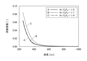
- FIG. 4 is a diagram showing the relationship between the gas flow rate ratio and the extinction coefficient in Example 1.
- FIG. 4 is a diagram showing the relationship between the gas flow rate ratio and the refractive index in Example 1.
- FIG. 11 is a diagram showing the relationship between the gas flow rate ratio and the water droplet contact angle in Example 1.
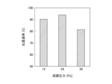
- FIG. 11 is a diagram showing the relationship between film formation pressure and light transmittance in Example 2.
- FIG. 4 is a diagram showing the relationship between the gas flow rate ratio and the light transmittance in Example 1.
- FIG. 13 is a diagram showing elemental contents of films formed at different pressures in Example 2.
- FIG. 11 is a diagram showing the relationship between the film formation pressure and the refractive index in Example 2.
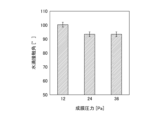
- FIG. 11 is a diagram showing the relationship between the film formation pressure and the water droplet contact angle in Example 2.
- FIG. 11 is a diagram showing element contents when the gas flow rate ratio is changed in Example 3.
- FIG. 11 is a diagram showing the relationship between the gas flow rate ratio and the refractive index in Example 3.
- FIG. 11 is a diagram showing the relationship between the gas flow rate ratio and the light transmittance in Example 3.
- FIG. 11 is a diagram showing the relationship between the gas flow rate ratio and the water droplet contact angle in Example 3.
- FIG. 11 is a diagram showing the relationship between the gas flow rate ratio and the film formation rate.
- ⁇ Configuration of fluorine-containing amorphous carbon film> 1 is a schematic diagram of a fluorine-containing amorphous carbon film 10 according to an embodiment formed on the surface of a substrate 11 as a base material.
- the fluorine-containing amorphous carbon film 10 is a single-layer thin film formed in a single film formation process.
- the thickness of the fluorine-containing amorphous carbon film 10 can be appropriately designed depending on the member to which the fluorine-containing amorphous carbon film 10 is applied, and is, for example, 25 nm to 500 nm, preferably 50 nm to 250 nm.
- the fluorine-containing amorphous carbon film 10 has a different fluorine content between a surface region and a region 12 deeper on the substrate 11 side.
- the fluorine-containing amorphous carbon film 10 is a single layer film made of carbon, fluorine, and oxygen.
- the fluorine-containing amorphous carbon film 10 is expressed as a film "made of carbon, fluorine, and oxygen" or a film “composed of carbon, fluorine, and oxygen,” this is intended to mean that trace amounts of impurities that are inevitably or unintentionally mixed in are not considered as constituent elements.
- the average fluorine content in the thickness direction of the fluorine-containing amorphous carbon film 10 is 30 atomic % to 40 atomic %, the average oxygen content in the thickness direction is 5 atomic % to 20 atomic %, and the remainder is carbon atoms.
- the fluorine content is 50 atomic % to 75 atomic %, the oxygen content is 5 atomic % to 20 atomic %, and the remainder is carbon atoms.
- the composition in the region 12 at a depth of 10 nm or more from the surface is fluorine content of 30 atomic % to 40 atomic %, oxygen content of 5 atomic % to 20 atomic %, and the remainder is carbon atoms.
- the average content of each element in the thickness direction is dominated by the composition of the region 12 at a depth of 10 nm or more from the surface.
- the fluorine-containing amorphous carbon film 10 is a highly hard film with a low refractive index and excellent water repellency, and has the functions of hard coat, anti-reflection, and anti-fouling in a single layer.
- the fluorine-containing amorphous carbon film 10 is applied to the surface of a glass substrate such as a display or transparent panel.
- the hard coat property is a property that suppresses the occurrence of scratches and cracks in the glass substrate when an external impact is applied, and includes abrasion resistance and scratch resistance. In order to be called a hard coat, not only is it possible to prevent scratches and cracks, but the film itself is required to have high hardness to protect the substrate.
- the substrate is formed of a glass material such as quartz glass, soda-lime glass, sapphire glass, or optical glass.
- the fluorine-containing amorphous carbon film 10 preferably has a hardness of 0.65 GPa or more as measured by the nanoindentation method.
- high light transmittance is also required.
- the light transmittance of the fluorine-containing amorphous carbon film 10 of the embodiment is 90%, preferably 95% or more, and more preferably 98% or more.
- Anti-reflection properties refer to the function of reducing light reflection by utilizing optical interference.
- the fluorine-containing amorphous carbon film 10 When the fluorine-containing amorphous carbon film 10 is applied to a display, it reduces light reflection on the display surface and improves visibility. To achieve this, it is required that the refractive index be low relative to the underlying substrate. Even in the highest case, the fluorine-containing amorphous carbon film 10 has a refractive index of 1.40 ⁇ 0.02, which is lower than the refractive index of quartz glass (1.50), and when formed under favorable conditions, the refractive index can be reduced to 1.32, providing a high anti-reflection function.
- Anti-soiling properties refer to the property of being resistant to adhesion of dirt.
- When applied to a display in order to prevent the adhesion of dirt and fingerprints on the outermost surface of the display, it is required that the surface free energy is small or that the contact angle with water is large (high water repellency).
- the fluorine-containing amorphous carbon film 10 has a large water droplet contact angle of 95° or more and is highly water repellent. The basis for this will be explained later.
- ⁇ Method for producing fluorine-containing amorphous carbon film> 2 is a schematic diagram of a film forming apparatus 100 used to produce the fluorine-containing amorphous carbon film 10.
- the fluorine-containing amorphous carbon film 10 is formed using a source gas whose chemical formula is represented only by carbon (C) and fluorine (F) and an inert gas. That is, a mixed gas of a fluorocarbon gas that does not contain hydrogen atoms and an inert gas is used.
- the film formation apparatus 100 is a CVD (Chemical Vapor Deposition) film formation apparatus.
- CVD has a high film formation speed, a large processing area, and can form a high density film compared to vacuum deposition.
- the film formation apparatus 100 is a capacitively coupled high frequency plasma CVD apparatus, and has a pair of parallel plate type electrodes 101 and 102 in a chamber 104.
- the chamber 104 is configured so that a substrate 11 can be placed between the electrodes 101 and 102, and for example, the substrate 11 can be placed on the lower electrode 101.
- the chamber 104 is maintained at a medium or high vacuum of 24 Pa or less.
- One electrode 101 is connected to a high-frequency power source 103, and the other electrode 102 is grounded.
- High-frequency power is applied between the electrodes 101 and 102 to generate plasma.
- Frequencies used to excite low-temperature plasma include the HF band (3 to 30 MHz), VHF band (30 to 300 MHz), and UHF band (300 to 3000 MHz), but in this embodiment, a power frequency of 13.56 MHz, which is common in plasma excitation processes, is used.
- a raw material gas and an inert gas that dilutes the raw material gas are introduced into the chamber 104 from the gas inlet Pin, and a gas plasma is generated in the chamber 104.
- the raw material gas molecules are decomposed by the plasma in the chamber 104, and the chemical species generated by the decomposition are deposited on the substrate 11. Unnecessary gas is exhausted from the exhaust port Pout.
- At least one gas selected from tetrafluoromethane ( CF4 ), hexafluoroethane ( C2F6 ), octafluoropropane ( C3F8 ), and octafluorocyclobutane ( C4F8 ) can be used.
- the inert gas for dilution is argon (Ar), nitrogen (N), krypton (Kr), xenon ( Xe ), etc.
- the method for producing a fluorine-containing amorphous carbon film includes the steps of: a) placing a substrate 11 in a chamber 104 of a film forming apparatus 100; b) introducing a source gas whose chemical formula is represented only by carbon and fluorine and an inert gas for diluting the source gas into the chamber 104, and forming a fluorine-containing amorphous carbon film on the surface of the substrate 11 under plasma generation; c) setting the mixture ratio of the inert gas to the source gas to be greater than 1/4 and less than 11/1 in terms of the flow rate into the chamber 104; More preferably, the flow rate ratio of the inert gas to the source gas into the chamber 104 is set to 1/2 or more and 7/2 or less. The reason for the preferable range of the mixture ratio of the inert gas to the source gas will be described later.
- Example 1 A SiO2 substrate is used as the substrate 11.
- the SiO2 substrate is placed on the electrode 101, and a high-frequency power of 13.56 MHz and 200 W is applied to the film-forming device 100 to excite low-temperature plasma.
- the pressure in the chamber 104 before plasma ignition is set to 24 Pa, and Ar gas and C4F8 gas are introduced into the chamber 104.
- the ratio of the flow rate of the Ar gas to the flow rate of the C4F8 gas ( Ar / C4F8 ) is changed to 1/4, 1/2, and 1/1.
- a high - frequency power is applied to generate plasma, and three types of samples are prepared by forming films with final film thicknesses of 50 nm, 100 nm, and 150 nm at each flow rate ratio.
- the film thickness, element content, light transmittance, extinction coefficient, refractive index, water droplet contact angle, and hardness are measured using the prepared samples.
- the film thickness is determined by creating a structural model of the thin film in a spectroscopic ellipsometry method used in measuring the extinction coefficient and refractive index, which will be described later, and then fitting the measured data.
- Elemental content The elemental content is measured using a sample with a film thickness of 150 nm, which is prepared by setting the Ar/ C4F8 flow rate ratio to 1/4 and 1/1, respectively.
- the elemental content of the sample surface and the inside of the film etched with Ar at an acceleration energy of 700 kV are measured by X-ray photoelectron spectroscopy (XPS).
- the depths of the film interior are 10 nm and 30 nm from the surface.
- the XPS device used is a JPS-9010TR manufactured by JEOL Ltd.
- the depth resolution of the film surface and the film interior is about 5 nm.
- the elemental content of the film interior is the same at a depth of 10 nm and 30 nm, so it is collectively referred to as the elemental content of the film interior.
- Element ratio of the film surface F content 50 atomic %, C content 38 atomic %, O content 12 atomic %
- Element ratio inside the film F content 32 atomic %, C content 58 atomic %, O content 10 atomic %, It is.
- Light transmittance Figure 3 shows the light transmittance characteristics of samples made with different film thicknesses and gas flow ratios.
- the light transmittance of samples made with film thicknesses set to 50 nm, 100 nm, and 150 nm for each of the three types of gas flow ratios described above is measured using an ultraviolet-visible spectrometer (UV- Vis3600Plus manufactured by Shimadzu Corporation).
- the gray circles indicate the light transmittance of samples with an Ar/ C4F8 flow ratio of 1/1
- the gray squares indicate the light transmittance of samples with an Ar/ C4F8 flow ratio of 1/2
- the white triangles indicate the light transmittance of samples with an Ar/ C4F8 flow ratio of 1/4.
- the slight variation in film thickness among samples is due to process variations.
- the film thickness is 100 nm or less, the light transmittance is 94% or more, and when the film thickness is 50 nm, the light transmittance is 97% or more. Even when the Ar/C 4 F 8 flow rate ratio is 1/4, the film has a high light transmittance that is applicable to displays.
- FIG. 4 shows the light absorption characteristics of samples prepared with different gas flow ratios.
- Sample A corresponds to the sample whose transmission characteristics are dependent on film thickness, indicated by gray squares in FIG. 3.
- Sample B corresponds to the sample whose transmission characteristics are dependent on film thickness, indicated by gray circles in FIG. 3.
- Sample C corresponds to the sample whose transmission characteristics are dependent on film thickness, indicated by white triangles in FIG. 3.
- the horizontal axis represents wavelength
- the vertical axis represents extinction coefficient.
- the extinction coefficient, together with the refractive index, which will be described later, is measured by spectroscopic ellipsometry using an imaging ellipsometer EP4 manufactured by Accurion.
- the extinction coefficient represents the degree of light absorption.
- the extinction coefficient at a wavelength of 350 nm is small, at 0.025 or less, and there is almost no light absorption for visible light.
- the extinction coefficient is 0.010 or less. Even when the Ar/C 4 F 8 flow rate ratio is 1/4, the extinction characteristics are sufficient for use in displays.
- FIG. 5 shows the refractive index at a wavelength of 550 nm of samples made with different gas flow ratios.
- the refractive index of the sample with an Ar/ C4F8 flow ratio of 1/2 is 1.40
- the refractive index of the sample with an Ar/ C4F8 flow ratio of 1/1 is 1.39.
- the refractive index of the sample with an Ar/ C4F8 flow ratio of 1/4 is 1.46.
- the sample with an Ar/ C4F8 flow ratio of 1/4 has good light transmittance and extinction coefficient, but the refractive index cannot be sufficiently reduced, making it difficult to apply in situations where anti-reflection function is required as a priority.
- FIG. 6 shows the water drop contact angle of samples prepared at different gas flow ratios.
- the water drop contact angle of each sample is measured by the sessile method using DM-500 manufactured by Kyowa Interface Science Co., Ltd.
- the water drop contact angle of the sample with an Ar/C 4 F 8 flow ratio of 1/2 is 95°
- the water drop contact angle of the sample with an Ar/ C 4 F 8 flow ratio of 1/4 is 92.5°. Both have sufficient water drop contact angles and have high antifouling effects.
- the water drop contact angle of the sample prepared by further increasing the Ar ratio to 2/1 is 101.7° and has high water repellency.
- the Ar/C 4 F 8 flow ratio is 1/4 or more, preferably 1/2 or more.
- the hardness of each sample is measured by nanoindentation.
- the film thickness is preferably 250 nm or more, so the hardness is measured using a sample with a film thickness of 250 nm.
- the measurement is performed using Nano Indenter G200 manufactured by Toyo Corporation.
- the hardness of the sample with an Ar/C 4 F 8 flow rate ratio of 1/2 is 0.76 GPa, and the hardness of the sample with an Ar/C 4 F 8 flow rate ratio of 1/1 is 0.65 GPa.
- the hardness of the sample with an Ar/C 4 F 8 flow rate ratio of 1/4 is 0.48 GPa, which is slightly less hard than the other samples.
- Example 1 in order to satisfy all the requirements for hard coating, anti-reflection, and anti-soiling, it is preferable that the flow rate ratio of the raw material gas (fluorocarbon gas) to the inert gas is greater than 1/4, and more preferably 1/2 or more.
- Example 2 In Example 2, the Ar/ C4F8 flow rate ratio is fixed, and the deposition pressure is changed to prepare a plurality of types of samples.
- the same high-frequency plasma CVD deposition apparatus 100 as in Example 1 is used.
- the inert gas is Ar
- the raw material gas is C4F8
- a high-frequency power of 13.56 MHz and 200 W is applied to the electrode 101 under reduced pressure, and plasma is excited between the electrode 102 facing the electrode 101 to deposit a fluorine-containing amorphous carbon film 10 on a quartz glass substrate 11 placed on the electrode 101.
- the Ar/ C4F8 flow rate ratio is set to 1/2, and the deposition pressure is changed to 12 Pa, 24 Pa, and 48 Pa.
- the film thickness, light transmittance, element content inside the film, refractive index, and water drop contact angle are measured for the samples prepared at each deposition pressure.
- Figure 7 shows the relationship between the film formation pressure and the light transmittance.
- the film formation pressure is shown as the composite pressure of the gas pressures in the chamber 104 during film formation.
- the film formation pressure is 12 Pa and 24 Pa, a light transmittance of 90% or more is obtained, but when the film formation pressure is 36 Pa, the light transmittance drops to less than 85%.
- Figure 8 shows the elemental content of films deposited at different pressures.
- the elemental content was measured at a depth of 20 nm from the film surface by etching and XPS. No significant difference was observed in the carbon (C) content, but the fluorine (F) content was 45 atomic % at deposition pressures of 12 Pa and 24 Pa, while it was 40 atomic % at a deposition pressure of 36 Pa, with the oxygen (O) content increasing accordingly.
- the deposition pressure it is desirable for the deposition pressure to be less than 36 Pa, for example 35 Pa or less, preferably 30 Pa or less, and more preferably 24 Pa or less.
- Figure 9 shows the relationship between the deposition pressure and the refractive index.
- the deposition pressure is 24 Pa, a refractive index of 1.38 is obtained, and when it is 12 Pa, a refractive index lower than 1.36 is realized.
- the deposition pressure is 36 Pa, the refractive index becomes 1.40.
- a refractive index of 1.40 can be used as an anti-reflective film, taking into consideration hardness and transparency, it can be seen that the deposition pressure is preferably less than 36 Pa, for example, 35 Pa or less, preferably 30 Pa or less, and more preferably 24 Pa or less.
- Figure 10 shows the relationship between the film formation pressure and the water droplet contact angle. At film formation pressures of 24 Pa and 36 Pa, a contact angle of nearly 95° was obtained, and at 12 Pa, a contact angle of over 100° was obtained. Even at a pressure of 36 Pa, a fluorine-containing amorphous carbon film with antifouling properties was obtained.
- Example 2 confirmed that in order to provide all the functions of hard coating, anti-reflection, and anti-soiling, the deposition pressure should be less than 36 Pa, for example, 35 Pa or less, preferably 30 Pa or less, and more preferably 24 Pa or less.
- the deposition speed also decreases as the deposition pressure decreases (1 nm/s at a deposition pressure of 24 Pa, and 0.5 nm/s at 12 Pa), in order to achieve a deposition speed suitable for practical use at the industrial level, it is desirable for the deposition pressure to be 6 Pa or more.
- Example 3 the composition and characteristics are evaluated by fixing the deposition pressure and increasing the ratio of the inert gas to the raw material gas.
- a quartz glass substrate 11 is placed in the same deposition apparatus 100 as in Examples 1 and 2, and the deposition pressure is fixed at 24 Pa.
- the inert gas is Ar gas
- the raw material gas is C 4 F 8 gas.
- the Ar/C 4 F 8 flow rate ratio is changed to 1/2, 3/2, 5/2, and 7/2 to prepare a sample with a film thickness of 250 nm, and the element content, refractive index, light transmittance, and water droplet contact angle are measured.
- the measurement method is the same as in Examples 1 and 2.
- Elemental content Figure 11 shows the elemental content in the film when the gas flow rate ratio is changed in Example 3. Etching is performed by accelerating Ar ions at 700 kV, and the elemental content in the thin film is measured by XPS using JPS-9010TR manufactured by JEOL Ltd. The surface layer is measured from the surface to a depth of 5 nm, the intermediate layer is measured from a depth of 80-160 nm, and the substrate vicinity is measured at a depth of 240 nm, and XPS is measured at each depth. In the surface layer to a depth of 5 nm, the fluorine (F) content increases as the Ar/C 4 F 8 flow rate ratio increases, and is 61 atomic % or more in all cases.
- F fluorine
- the F content is stable at 40 atomic % when the Ar/C 4 F 8 flow rate ratio is 1/2, 3/2, and 5/2, but when the flow rate ratio is increased to 7/, the F content increases to 43 atomic %. Even near the substrate, the F content is stable at nearly 40 atomic % except for the flow rate ratio of 3/2, and even at the flow rate ratio of 3/2, the F content is 30 atomic % or more. This result is consistent with the result of Example 1.
- the C element content is higher in the intermediate layer and near the substrate than in the surface layer. The O element content does not change significantly in the film thickness direction, and is not significantly affected by changes in the Ar / C4F8 flow rate ratio.
- Light transmittance Figure 13 shows the relationship between the Ar/ C4F8 flow rate ratio and the light transmittance.
- Each sample prepared in Example 3 is measured using ultraviolet-visible spectroscopy. For reference, light with a wavelength of 400 nm to 800 nm is transmitted through the sample of a quartz glass substrate 11 with no film formed on the surface, and the transmittance is measured. D "without film” is the transmission spectrum of a quartz glass substrate 11 with no film formed on the surface.
- the Ar/ C4F8 flow rate ratios of E, F, G, and H are 1/2, 3/2, 5/2, and 7/2, respectively. All samples have a transmittance of 90% or more in the visible light region, showing high light transmittance.
- FIG. 14 shows the relationship between the Ar/C 4 F 8 flow rate ratio and the water drop contact angle.
- the water drop contact angle is measured by the droplet method for each sample prepared in Example 3.
- the water drop contact angle of a quartz glass substrate with no film formed on its surface is measured. In all samples, the water drop contact angle is 90° or more.
- the water drop contact angle increases when the ratio of Ar gas is increased.
- the water drop contact angle is 94.6° when the flow rate ratio is 1/2, and the water drop contact angle is 100.3° when the flow rate ratio is 7/2.
- the water drop contact angle does not even reach 60°, and it can be seen that the fluorine-containing amorphous carbon film of Example 3 has a high antifouling effect.
- the fluorine-containing amorphous carbon film 10 of the embodiment is characterized in that the fluorine content in a region shallower than 10 nm from the surface is higher than the region 12 at a depth of 10 nm or more. If there are many CF bonds in the surface layer, polarization is suppressed, and interactions such as reverse polarization induced by light or electromagnetic waves are small, making it easy to transmit light and resulting in low refraction.
- the fluorine content inside the film is also 40 atomic % on average, and polarization inside the film is also suppressed, resulting in an extremely low refractive index.
- the fluorine-containing amorphous carbon film 10 of the embodiment has an amorphous carbon fluoride film with a high fluorine content formed near the surface, and also has a high fluorine content inside and does not contain hydrogen, resulting in extremely excellent optical properties.
- C4F8 is used as the raw material gas
- fluorocarbon gas such as CF4 , C2F6 , C3F8 , etc. may be used, or a mixture gas of two or more gases selected from CF4 , C2F6 , C3F8 , C4F8 may be used.
- the plasma excitation of Ar gas promotes the decomposition of fluorocarbon molecules, and promotes the radicalization and ionization of C, F, and CF groups.
- the flow rate of Ar gas is 50% or more of the flow rate of fluorocarbon raw material gas, the decomposition and activation of fluorocarbon gas are promoted, and the fluorine content in the film is increased.
- the fluorocarbon gas is dissociated by the Ar plasma to produce an amorphous CF film, but Ar ions also have an etching effect, and when the Ar gas flow rate is four times or more that of the fluorocarbon raw material gas, the etching effect becomes greater and the film formation speed decreases.
- Figure 15 shows the relationship between each flow rate ratio and the film formation speed at a film formation pressure of 24 Pa. The higher the Ar ratio, the lower the film formation speed, but if we extrapolate the bar graph in Figure 15, it is possible to increase the Ar gas flow rate ratio until the film formation speed drops to 0.1 nm/s, which is considered to be unsuitable for practical use at an industrial level, and further improvement in optical properties can be expected.
- the Ar gas flow rate ratio to the raw material gas can be increased to 11/1. From the above, it is preferable that the flow rate ratio of Ar gas to the raw material gas is greater than 1/4 and less than or equal to 11/1.
- the etching effect of Ar ions decreases, and activated CF radicals and CF ions accumulate near the surface to a thickness of several nm, forming an amorphous CF film with a high fluorine content.
- the higher the surface fluorine content the lower the surface reflectance due to weak polarization of the F atoms, and the better the optical properties are, such as increased light transmittance and a lower refractive index.
- the surface free energy decreases, increasing water repellency and improving anti-fouling properties.
- the fluorine-containing amorphous carbon film 10 of the embodiment is a single layer film made of carbon, fluorine, and oxygen, with an average fluorine content of 30 atomic % to 40 atomic % in the thickness direction, an average oxygen content of 5 atomic % to 20 atomic % in the thickness direction, and the remainder being carbon atoms.
- the region shallower than 10 nm deep from the surface becomes a high-concentration fluorine-containing region 13, with a fluorine content of 50 atomic % to 75 atomic % in the thickness direction, an oxygen content of 5 atomic % to 20 atomic % in the thickness direction, and the remainder being carbon atoms.
- the fluorine-containing amorphous carbon film 10 of the embodiment is a thin film with excellent optical properties (low reflectance, high light transmittance, low refractive index) and excellent anti-fouling properties, and is highly hard, making it suitable as a protective coating for mobile displays such as smartphones.
- the film can be formed at low cost in a short time using plasma CVD at low pressure.
- the fluorine-containing amorphous carbon film 10 can be formed at low cost in a single film formation process, and is also advantageous in terms of cost. Using a raw material gas whose chemical formula is represented only by carbon and fluorine, a thin film with excellent optical properties and anti-fouling properties can be produced at low cost, making it suitable for mass production of protective films for displays and transparent panels.
- a fluorine-containing amorphous carbon film It is composed of a single layer of carbon, fluorine, and oxygen, an average fluorine content in the film thickness direction is 30 atomic % or more and 40 atomic % or less, an average oxygen content in the film thickness direction is 5 atomic % or more and 20 atomic % or less, and the remainder is carbon atom; Fluorine-containing amorphous carbon film.
- (Item 2) a high-concentration fluorine-containing region having a higher fluorine content in a region shallower than 10 nm in depth from the surface than in a region having a depth of 10 nm or more; the high-concentration fluorine-containing region has a fluorine content of 50 atomic % or more and 75 atomic % or less, an oxygen content of 5 atomic % or more and 20 atomic % or less, and the remainder being carbon atoms;
- Item 2 A fluorine-containing amorphous carbon film according to item 1.
- the refractive index of the monolayer film is 1.32 or more and less than 1.40.
- Item 3. A fluorine-containing amorphous carbon film according to item 1 or 2.
- the light transmittance of the monolayer film is 90% or more.
- Item 4. A fluorine-containing amorphous carbon film according to any one of items 1 to 3. (Item 5) The water droplet contact angle of the monolayer film is 90° or more.
- Item 5. A fluorine-containing amorphous carbon film according to any one of items 1 to 4. (Item 6) The hardness of the monolayer film is 0.65 GPa or more as measured by a nanoindentation method.
- Item 6. A fluorine-containing amorphous carbon film according to any one of items 1 to 5.
- the thickness of the monolayer film is 25 nm or more and 500 nm or less.
- a fluorine-containing amorphous carbon film according to any one of items 1 to 6. (Item 8) The thickness of the monolayer film is 50 nm to 250 nm.
- Item 8. A fluorine-containing amorphous carbon film according to item 7. (Item 9) A substrate is placed in the chamber; A source gas whose chemical formula is represented only by carbon and fluorine and an inert gas for diluting the source gas are introduced into the chamber, and a fluorine-containing amorphous carbon film is formed on the surface of the substrate under plasma generation; A mixing ratio of the inert gas to the source gas is set to be greater than 1/4 and smaller than 11/1 in terms of a flow rate ratio into the chamber; A method for producing a fluorine-containing amorphous carbon film.
- a mixing ratio of the inert gas to the source gas is set to 1/2 or more and 7/2 or less in terms of a flow rate ratio into the chamber;
- Item 10 A method for producing a fluorine-containing amorphous carbon film according to item 9.
- (Item 11) Set the pressure in the chamber to 24 Pa or less.
- Item 11. A method for producing a fluorine-containing amorphous carbon film according to item 9 or 10.
- the source gas is CF4 , C2F6 , C3F8 , C4F8 , or a mixed gas of two or more gases selected therefrom ;
- Item 11 A method for producing a fluorine-containing amorphous carbon film according to any one of items 9 and 10.
- the inert gas is Ar gas.
- Item 13 A method for producing a fluorine-containing amorphous carbon film according to any one of items 9 to 12.
Landscapes
- Chemical & Material Sciences (AREA)
- Physics & Mathematics (AREA)
- General Physics & Mathematics (AREA)
- Optics & Photonics (AREA)
- Chemical Kinetics & Catalysis (AREA)
- Materials Engineering (AREA)
- General Chemical & Material Sciences (AREA)
- Engineering & Computer Science (AREA)
- Inorganic Chemistry (AREA)
- Organic Chemistry (AREA)
- Mechanical Engineering (AREA)
- Metallurgy (AREA)
- Life Sciences & Earth Sciences (AREA)
- Geochemistry & Mineralogy (AREA)
- Chemical Vapour Deposition (AREA)
- Surface Treatment Of Optical Elements (AREA)
- Surface Treatment Of Glass (AREA)
Abstract
ハードコート、反射防止、及び防汚の特性を合わせ持つフッ素含有非晶質炭素膜とその製造方法を提供する。フッ素含有非晶質炭素膜は、炭素、フッ素、及び酸素からなる単層膜であり、膜厚方向での平均フッ素含有率が30原子%以上40原子%以下、膜厚方向での平均酸素含有率が5原子%以上20原子%以下であり、残りが炭素原子である。このフッ素含有非晶質炭素膜は、チャンバ内に基板を設置し、化学式が炭素とフッ素のみで表される原料ガスと、前記原料ガスを希釈する不活性ガスを前記チャンバ内に導入して、プラズマ発生下で前記基板上にフッ素含有非晶質炭素膜を形成し、前記原料ガスに対する前記不活性ガスの混合比を、前記チャンバ内への流量比で1/4よりも大きく、11/1よりも小さく設定する。
Description
本発明は、フッ素含有非晶質炭素膜、及びその製造方法に関し、特に、低屈折率かつ撥水性の良い硬質のコーティングを実現するフッ素含有非晶質炭素膜とその製造方法に関する。
スマートフォン、タブレット端末などの携帯ディスプレイデバイスにおいて、ディスプレイの基材となるガラス基板の表面に、何層もの機能層が積層されている。たとえば、擦り傷や損傷の発生防止のためのハードコート層、光の反射低減のための反射防止層、汚れや指紋の付着防止のための防汚層が設けられている。低屈折率の反射防止膜を形成するために、フッ素含有アルコキシシランを利用したコーティング液が提案されている(たとえば、特許文献1参照)。また、ハードコーティング層と、中空無機ナノ粒子を含む低屈折率層を積層した耐スクラッチ性、及び防汚性を有する反射防止フィルムが提案されている(たとえば、特許文献2参照)。
従来のディスプレイデバイスは、反射防止層、防汚層という、異なる機能をもつ複数の薄膜でコーティングされるため、その生産プロセスは複雑で、コストも高い。特許文献1で提案される低屈折率の反射防止膜を用いる場合、別途ハードコーティング層と防汚層が必要になる。特許文献2で提案される反射防止フィルムは、ハードコーティング層と低屈折率層の複合膜であり、その生産方法は複雑でコストが高い。
本発明は、上記の問題に鑑みて、ハードコート、反射防止、及び防汚の特性を合わせ持つフッ素含有非晶質炭素膜とその製造方法を提供することを目的とする。
本発明の一つの側面で、フッ素含有非晶質炭素膜は、炭素、フッ素、及び酸素からなる単層膜であり、膜厚方向での平均フッ素含有率が30原子%以上40原子%以下、膜厚方向での平均酸素含有率が5原子%以上20原子%以下であり、残りが炭素原子である。
本発明の別の側面で、フッ素含有非晶質炭素膜の製造方法は、
チャンバ内に基板を設置し、
化学式が炭素とフッ素のみで表される原料ガスと、前記原料ガスを希釈する不活性ガスを前記チャンバ内に導入して、プラズマ発生下で前記基板の表面にフッ素含有非晶質炭素膜を形成し、
前記原料ガスに対する前記不活性ガスの混合比を、前記チャンバ内への流量比で1/4よりも大きく、11/1よりも小さく設定する。
チャンバ内に基板を設置し、
化学式が炭素とフッ素のみで表される原料ガスと、前記原料ガスを希釈する不活性ガスを前記チャンバ内に導入して、プラズマ発生下で前記基板の表面にフッ素含有非晶質炭素膜を形成し、
前記原料ガスに対する前記不活性ガスの混合比を、前記チャンバ内への流量比で1/4よりも大きく、11/1よりも小さく設定する。
ハードコート、反射防止、及び防汚の特性を合わせ持つフッ素含有非晶質炭素膜とその製造方法が実現される。
以下で、図面を参照して本発明のフッ素含有非晶質炭素膜とその製造方法について詳細に述べる。下記の実施形態は、発明の技術思想を具体化するための例示であり、本発明を記載された構成や数値に限定するものではない。図面中、同一の機能を有する構成要素には、同一符号を付して、重複する記載を省略する場合がある。異なる実施形態や構成例の間での部分的な置換または組み合わせは可能である。各図面が示す各部材の大きさ、位置関係等は、発明の理解を容易にするために誇張して描かれている場合がある。
<フッ素含有非晶質炭素膜の構成>
図1は、基材としての基板11の表面に成膜された実施形態のフッ素含有非晶質炭素膜10の模式図である。フッ素含有非晶質炭素膜10は、一回の成膜工程で形成される単層の薄膜である。フッ素含有非晶質炭素膜10の厚さは、フッ素含有非晶質炭素膜10が適用される部材に応じて適宜設計可能であり、たとえば、25nm以上500nm以下、好ましくは、50nm以上250nmである。フッ素含有非晶質炭素膜10は、表面領域と、それよりも深い基板11側の領域12で、フッ素の含有率が異なる。フッ素含有非晶質炭素膜10の表面近傍、具体的には表面から10nmよりも浅い領域は、深さが10nm以上の領域12よりもフッ素の含有率が高い高濃度フッ素含有領域13である。
図1は、基材としての基板11の表面に成膜された実施形態のフッ素含有非晶質炭素膜10の模式図である。フッ素含有非晶質炭素膜10は、一回の成膜工程で形成される単層の薄膜である。フッ素含有非晶質炭素膜10の厚さは、フッ素含有非晶質炭素膜10が適用される部材に応じて適宜設計可能であり、たとえば、25nm以上500nm以下、好ましくは、50nm以上250nmである。フッ素含有非晶質炭素膜10は、表面領域と、それよりも深い基板11側の領域12で、フッ素の含有率が異なる。フッ素含有非晶質炭素膜10の表面近傍、具体的には表面から10nmよりも浅い領域は、深さが10nm以上の領域12よりもフッ素の含有率が高い高濃度フッ素含有領域13である。
フッ素含有非晶質炭素膜10は、炭素、フッ素、及び酸素からなる単層膜である。実施形態、及び特許請求の範囲で、フッ素含有非晶質炭素膜10を「炭素、フッ素、及び酸素からなる」膜、あるいは「炭素、フッ素、及び酸素で構成される」膜として表現されるときは、不可避的に、あるいは意図せずに混入する微量の不純物を構成元素として考慮しないという趣旨である。
フッ素含有非晶質炭素膜10の膜厚方向での平均フッ素含有率は、30原子%以上40原子%以下、膜厚方向での平均酸素含有率が5原子%以上20原子%以下であり、残りが炭素原子である。表面の高濃度フッ素含有領域13では、フッ素の含有率が50原子%以上75原子%以下、酸素の含有率が5原子%以上20原子%以下であり、残りが炭素原子である。表面から10nm以上の深さの領域12での組成は、フッ素含有率が30原子%以上40原子%以下、酸素含有率が5原子%以上20原子%以下であり、残りが炭素原子である。膜厚方向での各元素の平均含有率は、表面から10nm以上の深さの領域12の組成が支配的となっている。
フッ素含有非晶質炭素膜10は、低屈折率かつ撥水性に優れた高硬質の膜であり、単層でハードコート、反射防止、及び防汚の機能を合わせもつ。フッ素含有非晶質炭素膜10は、ディスプレイや透明パネル等のガラス基材の表面に適用される。ハードコート性は、外部から衝撃が加わった際に、ガラス基材に傷やクラックが生じることを抑制する性質であり、耐摩耗性や、耐スクラッチ性が含まれる。ハードコートと呼ぶためには、傷、クラックを防止できるだけでなく、基材を保護するために膜自体が高い硬度をもつことが求められる。基材は、石英ガラス、ソーダ石灰ガラス、サファイアガラス、光学ガラスなどのガラス材料で形成されている。基材を保護するために、フッ素含有非晶質炭素膜10は、好ましくはナノインデンテーション法による硬度で0.65GPa以上の硬度をもつ。ディスプレイ端末や透明パネルに適用される場合は、高い光透過率も求められる。後述するように、実施形態のフッ素含有非晶質炭素膜10の光透過率は90%、好ましくは95%以上、より好ましくは98%以上である。
反射防止特性は、光学的干渉作用を利用して光の反射を低減する機能をいう。フッ素含有非晶質炭素膜10がディスプレイに適用される場合は、ディスプレイ表面での光の反射を低減して、視認性を高める。このためには、下地の基材に対して屈折率が低いことが求められる。フッ素含有非晶質炭素膜10は、屈折率が最も高い場合においても、1.40±0.02と石英ガラスの屈折率(1.50)に比べて低く、好ましい条件で成膜した場合は、屈折率は1.32まで低下させることが可能であり、高い反射防止機能を有する。
防汚特性は、汚れの付きにくい性質をいう。ディスプレイに適用される場合、ディスプレイの最外面で汚れや指紋の付着を防止するため、表面自由エネルギーが小さい、あるいは、水に対する接触角が大きい(撥水性の高い)ことが求められる。フッ素含有非晶質炭素膜10は、水滴接触角が95°以上と大きく、高い撥水性をもつ。この根拠についても後述する。
<フッ素含有非晶質炭素膜の製造方法>
図2は、フッ素含有非晶質炭素膜10の作製に用いる成膜装置100の模式図である。フッ素含有非晶質炭素膜10は、化学式が炭素(C)とフッ素(F)のみで表される原料ガスと、不活性ガスを用いて形成される。すなわち、水素原子を含まないフッ化炭素系のガスと、不活性ガスとの混合ガスを用いる。
図2は、フッ素含有非晶質炭素膜10の作製に用いる成膜装置100の模式図である。フッ素含有非晶質炭素膜10は、化学式が炭素(C)とフッ素(F)のみで表される原料ガスと、不活性ガスを用いて形成される。すなわち、水素原子を含まないフッ化炭素系のガスと、不活性ガスとの混合ガスを用いる。
成膜装置100は、CVD(Chemical Vapor Deposition:化学気相成長)成膜装置である。CVDは、成膜速度が速く、処理面積が大きく、真空蒸着と比べて高密度の膜を形成できる。この例で、成膜装置100は容量結合型の高周波プラズマCVD装置であり、チャンバ104内に平行平板型の一対の電極101と102を有する。チャンバ104は電極101と102の間に基板11を設置できるように構成されており、たとえば、下部の電極101上に基板11を設置可能である。
成膜時に、チャンバ104内は24Pa以下の中真空または高真空に維持される。一方の電極101は高周波電源103に接続され、他方の電極102は接地されている。電極101と102の間に高周波パワーを印加してプラズマを発生させる。低温プラズマの励起に使用される周波数には、HF帯(3~30MHz)、VHF帯(30~300MHz)、UHF帯(300~3000MHz)があるが、実施形態では、プラズマ励起プロセスで一般的な13.56MHzの電源周波数を用いる。ガス流入口Pinから、原料ガスと、原料ガスを希釈する不活性ガスとがチャンバ104内に導入され、チャンバ104内にガスプラズマが発生する。チャンバ104内のプラズマによって原料ガス分子が分解され、分解により生成された化学種が基板11の上に堆積する。不要なガスは排気口Poutから排気される。
原料ガスとして、四フッ化メタン(CF4)、六フッ化エタン(C2F6)、八フッ化プロパン(C3F8)、八フッ化シクロブタン(C4F8)から選ばれる少なくとも一種のガスを用いることができる。希釈用の不活性ガスは、アルゴン(Ar)、窒素(N)、クリプトン(Kr)、キセノン(Xe)等である。原料ガスとして、水素原子を含まないフッ化炭素系ガスを用いることで、分極により屈折率を増大させがちなCH結合を排除することができる。
フッ素含有非晶質炭素膜の製造方法は、
a)成膜装置100のチャンバ104内に基板11を設置し、
b)化学式が炭素とフッ素のみで表される原料ガスと、原料ガスを希釈する不活性ガスをチャンバ104内に導入し、プラズマ発生下で基板11の表面にフッ素含有非晶質炭素膜を形成し、
c)原料ガスに対する不活性ガスの混合比を、チャンバ104内への流量比で1/4よりも大きく、11/1より小さく設定する、
工程を含む。より好ましくは、原料ガスに対する不活性ガスのチャンバ104内への流量比は、1/2以上、7/2以下とする。原料ガスに対する不活性ガスの混合比の好ましい範囲の根拠については、後述する。
a)成膜装置100のチャンバ104内に基板11を設置し、
b)化学式が炭素とフッ素のみで表される原料ガスと、原料ガスを希釈する不活性ガスをチャンバ104内に導入し、プラズマ発生下で基板11の表面にフッ素含有非晶質炭素膜を形成し、
c)原料ガスに対する不活性ガスの混合比を、チャンバ104内への流量比で1/4よりも大きく、11/1より小さく設定する、
工程を含む。より好ましくは、原料ガスに対する不活性ガスのチャンバ104内への流量比は、1/2以上、7/2以下とする。原料ガスに対する不活性ガスの混合比の好ましい範囲の根拠については、後述する。
<特性評価>
以下で、フッ素含有非晶質炭素膜10の成膜条件を変えて複数種類のサンプルを作製し特性を評価する。
以下で、フッ素含有非晶質炭素膜10の成膜条件を変えて複数種類のサンプルを作製し特性を評価する。
<実施例1>
基板11としてSiO2基板を用いる。SiO2基板を電極101の上に設置し、成膜装置100に、13.56MHz、200Wの高周波パワーを印加して、低温プラズマを励起する。プラズマ着火前のチャンバ104内の圧力を24Paに設定し、チャンバ104にArガスとC4F8ガスを導入する。C4F8ガスに対するArガスの導入流量の比率(Ar/C4F8)を、1/4、1/2、1/1と変える。高周波パワーを印加してプラズマを発生させ、それぞれの流量比で、最終膜厚が50nm、100nm、及び150nmとなるように成膜した3種類のサンプルを作製する。作製したサンプルを用いて、膜厚、元素含有率、光透過率、消衰係数、屈折率、水滴接触角、及び硬度を測定する。膜厚は、後述する消衰係数、及び屈折率の測定で用いる分光エリプソメトリ法において薄膜の構造モデルを作成したうえで、測定データのフィッティングにより求める。
基板11としてSiO2基板を用いる。SiO2基板を電極101の上に設置し、成膜装置100に、13.56MHz、200Wの高周波パワーを印加して、低温プラズマを励起する。プラズマ着火前のチャンバ104内の圧力を24Paに設定し、チャンバ104にArガスとC4F8ガスを導入する。C4F8ガスに対するArガスの導入流量の比率(Ar/C4F8)を、1/4、1/2、1/1と変える。高周波パワーを印加してプラズマを発生させ、それぞれの流量比で、最終膜厚が50nm、100nm、及び150nmとなるように成膜した3種類のサンプルを作製する。作製したサンプルを用いて、膜厚、元素含有率、光透過率、消衰係数、屈折率、水滴接触角、及び硬度を測定する。膜厚は、後述する消衰係数、及び屈折率の測定で用いる分光エリプソメトリ法において薄膜の構造モデルを作成したうえで、測定データのフィッティングにより求める。
(1)元素含有率
Ar/C4F8流量比を、それぞれ1/4と1/1に設定して作製された膜厚150nmのサンプルを用いて、元素含有率を測定する。サンプルの表面と、加速エネルギー700kVでArエッチングした膜内部の元素割合を、X線光電子分光法(XPS:X-ray Photoelectron Spectroscopy)により測定する。膜内部の測定の深さは、表面から10nm、30nmである。XPS装置として、日本電子株式会社製のJPS-9010TRを用いる。膜表面、及び膜内部の測定の深さ分解能は約5nmである。膜内部の元素割合は、深さ10nmと30nmで同じであったので、まとめて膜内部の元素割合とする。
Ar/C4F8流量比を、それぞれ1/4と1/1に設定して作製された膜厚150nmのサンプルを用いて、元素含有率を測定する。サンプルの表面と、加速エネルギー700kVでArエッチングした膜内部の元素割合を、X線光電子分光法(XPS:X-ray Photoelectron Spectroscopy)により測定する。膜内部の測定の深さは、表面から10nm、30nmである。XPS装置として、日本電子株式会社製のJPS-9010TRを用いる。膜表面、及び膜内部の測定の深さ分解能は約5nmである。膜内部の元素割合は、深さ10nmと30nmで同じであったので、まとめて膜内部の元素割合とする。
具体的には、Ar/C4F8流量比が1/4のサンプルで、
・膜表面の元素割合:F含有率50原子%、C含有率38原子%、O含有率12原子%、
・膜内部の元素割合:F含有率32原子%、C含有率58原子%、O含有率10原子%、
である。
・膜表面の元素割合:F含有率50原子%、C含有率38原子%、O含有率12原子%、
・膜内部の元素割合:F含有率32原子%、C含有率58原子%、O含有率10原子%、
である。
一方、Ar/C4F8流量比が1/1のサンプルで、
・膜表面の元素割合:F含有率73原子%、C含有率23原子%、O含有率4原子%、
・膜内部の元素割合:F含有率38原子%、C含有率54原子%、O含有率8原子%、
である。Ar/C4F8流量比を1/1にすることで、膜表面のF含有率は73原子%に向上した。膜内部でも、膜表面ほどではないがF含有率が増加している。Ar/C4F8流量比は、フッ素含有非晶質炭素膜10の膜厚方向の元素プロファイルに影響することがわかる。
・膜表面の元素割合:F含有率73原子%、C含有率23原子%、O含有率4原子%、
・膜内部の元素割合:F含有率38原子%、C含有率54原子%、O含有率8原子%、
である。Ar/C4F8流量比を1/1にすることで、膜表面のF含有率は73原子%に向上した。膜内部でも、膜表面ほどではないがF含有率が増加している。Ar/C4F8流量比は、フッ素含有非晶質炭素膜10の膜厚方向の元素プロファイルに影響することがわかる。
(2)光透過率
図3は、異なる膜厚とガス流量比で作製されたサンプルの光透過特性を示す。上述した3種類のガス流量比のそれぞれについて膜厚を50nm、100nm、及び150nmに設定して作製したサンプルの光透過率を、紫外可視分光器(島津製作所製のUV-Vis3600Plus)により測定する。グレイの丸印はAr/C4F8流量比が1/1のサンプルの光透過率、グレイの四角はAr/C4F8流量比が1/2のサンプルの光透過率、白三角はAr/C4F8流量比が1/4のサンプルの光透過率を示す。サンプルによって膜厚が若干ばらついているのは、プロセスばらつきによるものである。ガス流量比にかかわらず、すべてのサンプルで高い光透過率が達成されている。膜厚が150nmになっても90%を超える光透過率が得られ、ディスプレイの保護膜として実用性が高い。膜厚が100nm以下のときは、光線透過率が94%以上になり、膜厚が50nmで、光透過率は97%以上になる。Ar/C4F8流量比が1/4の場合でも、ディスプレイに適用可能な高い光透過率を有する。
図3は、異なる膜厚とガス流量比で作製されたサンプルの光透過特性を示す。上述した3種類のガス流量比のそれぞれについて膜厚を50nm、100nm、及び150nmに設定して作製したサンプルの光透過率を、紫外可視分光器(島津製作所製のUV-Vis3600Plus)により測定する。グレイの丸印はAr/C4F8流量比が1/1のサンプルの光透過率、グレイの四角はAr/C4F8流量比が1/2のサンプルの光透過率、白三角はAr/C4F8流量比が1/4のサンプルの光透過率を示す。サンプルによって膜厚が若干ばらついているのは、プロセスばらつきによるものである。ガス流量比にかかわらず、すべてのサンプルで高い光透過率が達成されている。膜厚が150nmになっても90%を超える光透過率が得られ、ディスプレイの保護膜として実用性が高い。膜厚が100nm以下のときは、光線透過率が94%以上になり、膜厚が50nmで、光透過率は97%以上になる。Ar/C4F8流量比が1/4の場合でも、ディスプレイに適用可能な高い光透過率を有する。
(3)消衰係数
図4は、異なるガス流量比で作製されたサンプルの光吸収特性を示す。サンプルAは、図3でグレイの四角で透過特性の膜厚依存性を示したサンプルに対応する。サンプルBは、図3でグレイの丸印で透過特性の膜厚依存性を示したサンプルに対応する。サンプルCは、図3で白の三角で透過特性の膜厚依存性を示したサンプルに対応する。横軸に波長、縦軸に消衰係数をとっている。消衰係数は、後述する屈折率とともに、Accurion社製のイメージグエリプソメータEP4を使用して分光エリプソメトリ法により測定する。消衰係数は、光の吸収程度を表す。すべてのサンプルで、波長350nmにおける消衰係数が0.025以下と小さく、可視光に対する光吸収がほとんどない。特に、Ar/C4F8流量比が1/2になると、消衰係数は0.010以下になる。Ar/C4F8流量比が1/4の場合でも、十分にディスプレイに適用可能な消衰特性を示す。
図4は、異なるガス流量比で作製されたサンプルの光吸収特性を示す。サンプルAは、図3でグレイの四角で透過特性の膜厚依存性を示したサンプルに対応する。サンプルBは、図3でグレイの丸印で透過特性の膜厚依存性を示したサンプルに対応する。サンプルCは、図3で白の三角で透過特性の膜厚依存性を示したサンプルに対応する。横軸に波長、縦軸に消衰係数をとっている。消衰係数は、後述する屈折率とともに、Accurion社製のイメージグエリプソメータEP4を使用して分光エリプソメトリ法により測定する。消衰係数は、光の吸収程度を表す。すべてのサンプルで、波長350nmにおける消衰係数が0.025以下と小さく、可視光に対する光吸収がほとんどない。特に、Ar/C4F8流量比が1/2になると、消衰係数は0.010以下になる。Ar/C4F8流量比が1/4の場合でも、十分にディスプレイに適用可能な消衰特性を示す。
(4)屈折率
図5は、異なるガス流量比で作製されたサンプルの波長550nmにおける屈折率を示す。Ar/C4F8流量比が1/2のサンプルの屈折率は1.40、Ar/C4F8流量比が1/1のサンプルの屈折率は1.39である。これに対し、Ar/C4F8流量比が1/4のサンプルの屈折率は、1.46である。Ar/C4F8流量比が1/4のサンプルは、光透過率や消衰係数は良好であるが、屈折率を十分に下げることができず、反射防止機能が優先的に求められる場面では適用が難しい。
図5は、異なるガス流量比で作製されたサンプルの波長550nmにおける屈折率を示す。Ar/C4F8流量比が1/2のサンプルの屈折率は1.40、Ar/C4F8流量比が1/1のサンプルの屈折率は1.39である。これに対し、Ar/C4F8流量比が1/4のサンプルの屈折率は、1.46である。Ar/C4F8流量比が1/4のサンプルは、光透過率や消衰係数は良好であるが、屈折率を十分に下げることができず、反射防止機能が優先的に求められる場面では適用が難しい。
(5)水滴接触角
図6は、異なるガス流量比で作製されたサンプルの水滴接触角を示す。各サンプルの水滴接触角を、協和界面化学株式会社製のDM-500を用いて、液滴法により測定する。Ar/C4F8流量比が1/2のサンプルの水滴接触角は95°、Ar/C4F8流量比が1/4のサンプルの水滴接触角は92.5°である。双方ともに十分な水滴接触角を持ち、防汚効果が高い。参考として、Ar比率をさらに高くしてAr/C4F8流量比を2/1にして作製したサンプルの水滴接触角は、101.7°であり、高い撥水性をもつ。ここから、防汚の観点から、Ar/C4F8流量比は1/4以上、好ましくは1/2以上である。
図6は、異なるガス流量比で作製されたサンプルの水滴接触角を示す。各サンプルの水滴接触角を、協和界面化学株式会社製のDM-500を用いて、液滴法により測定する。Ar/C4F8流量比が1/2のサンプルの水滴接触角は95°、Ar/C4F8流量比が1/4のサンプルの水滴接触角は92.5°である。双方ともに十分な水滴接触角を持ち、防汚効果が高い。参考として、Ar比率をさらに高くしてAr/C4F8流量比を2/1にして作製したサンプルの水滴接触角は、101.7°であり、高い撥水性をもつ。ここから、防汚の観点から、Ar/C4F8流量比は1/4以上、好ましくは1/2以上である。
(6)硬度
各サンプルの硬度をナノインデンテーション法により測定する。ナノインデンテーション法で測定する場合は、膜厚は250nm以上であることが好ましいため、硬度に関しては、膜厚250nmのサンプルを用いて測定する。測定は、株式会社東陽テクニカ製のNano Indenter G200を用いる。Ar/C4F8流量比が1/2のサンプルの硬度は0.76GPa、Ar/C4F8流量比が1/1のサンプルの硬度は0.65GPaである。Ar/C4F8流量比が1/4のサンプルの硬度は0.48GPaであり、他のサンプルと比較して硬度がやや不足する。
各サンプルの硬度をナノインデンテーション法により測定する。ナノインデンテーション法で測定する場合は、膜厚は250nm以上であることが好ましいため、硬度に関しては、膜厚250nmのサンプルを用いて測定する。測定は、株式会社東陽テクニカ製のNano Indenter G200を用いる。Ar/C4F8流量比が1/2のサンプルの硬度は0.76GPa、Ar/C4F8流量比が1/1のサンプルの硬度は0.65GPaである。Ar/C4F8流量比が1/4のサンプルの硬度は0.48GPaであり、他のサンプルと比較して硬度がやや不足する。
実施例1において、上記の特性評価によると、ハードコート、反射防止、及び防汚のすべての要求を満たすためには、不活性ガスに対する原料ガス(フッ化炭素ガス)の流量比は1/4よりも大きいことが望ましく、1/2以上であることがさらに望ましい。
<実施例2>
実施例2では、Ar/C4F8流量比を固定にし、成膜圧力を変化させて複数種類のサンプルを作製する。実施例1と同じ高周波プラズマCVDの成膜装置100を用いる。不活性ガスをAr、原料ガスをC4F8とし、減圧状態で13.56MHz、200Wの高周波電力を電極101に印加して、対向する電極102との間でプラズマ励起して、電極101の上に設置した石英ガラスの基板11の上にフッ素含有非晶質炭素膜10を成膜する。Ar/C4F8流量比を1/2に設定し、成膜圧力を12Pa、24Pa、48Paと変化させる。各成膜圧力で作製されたサンプルについて、膜厚、光透過率、膜内部の元素含有率、屈折率、及び水滴接触角を測定する。
実施例2では、Ar/C4F8流量比を固定にし、成膜圧力を変化させて複数種類のサンプルを作製する。実施例1と同じ高周波プラズマCVDの成膜装置100を用いる。不活性ガスをAr、原料ガスをC4F8とし、減圧状態で13.56MHz、200Wの高周波電力を電極101に印加して、対向する電極102との間でプラズマ励起して、電極101の上に設置した石英ガラスの基板11の上にフッ素含有非晶質炭素膜10を成膜する。Ar/C4F8流量比を1/2に設定し、成膜圧力を12Pa、24Pa、48Paと変化させる。各成膜圧力で作製されたサンプルについて、膜厚、光透過率、膜内部の元素含有率、屈折率、及び水滴接触角を測定する。
図7は、成膜圧力と光透過率の関係を示す。成膜圧力は、成膜時のチャンバ104内のガス圧の合成圧力として示されている。成膜圧力が12Paと24Paのときは90%以上の光透過率が得られているが36Paのときは光透過率が85%未満に低下している。ここから、成膜圧力を36Pa未満、たとえば、35Pa以下、好ましくは30Pa以下、より好ましくは24Pa以下とするのが好ましい。
図8は、異なる圧力で成膜された膜の元素含有率を示す。エッチングとXPSにより膜表面から20nmの深さで元素含有率を測定する。炭素(C)含有率に大きな差はみられないが、フッ素(F)含有率は、成膜圧力が12Paと24Paで45原子%であるのに対し、成膜圧力36Paで40原子%になり、その分酸素(O)含有率が増えている。フッ素割合を高くして屈折率を下げ、かつ、硬度と透明度を確保するためには、成膜圧力は36Pa未満、たとえば、35Pa以下、好ましくは30Pa以下、より好ましくは24Pa以下であることが望ましい。
図9は、成膜圧力と屈折率の関係を示す。成膜圧力が24Paのときは、屈折率1.38が得られ、12Paのときは1.36よりも低い屈折率が実現される。成膜圧力36Paで、屈折率は1.40になる。屈折率1.40でも反射防止膜として使用され得るが、硬度と透明度を考え合わせると、成膜圧力は36Pa未満、たとえば、35Pa以下、好ましくは30Pa以下、より好ましくは24Pa以下が好ましいことがわかる。
図10は、成膜圧力と水滴接触角の関係を示す。成膜圧力が24Paと36Paで、95°近くの接触角が得られ、12Paで100°を超える接触角が得られる。圧力36Paでも防汚効果のあるフッ素含有非晶質炭素膜が得られる。
実施例2の結果から、ハードコート、反射防止、及び防汚のすべての機能を持たせるには、成膜圧力は36Pa未満、たとえば、35Pa以下、好ましくは30Pa以下であり、24Pa以下がより好ましいと確認された。一方、成膜圧力が小さくなると成膜速度も減少することから(成膜圧力24Paで1nm/s、12Paでは0.5nm/s)、工業レベルで実用に適した成膜速度を実現するためには、成膜圧力は6Pa以上であるのが望ましい。
<実施例3>
実施例3では、成膜圧力を固定して、原料ガスに対する不活性ガスの割合を高くする方向に変化させて、組成と特性を評価する。実施例1、及び2と同じ成膜装置100に、石英ガラスの基板11を設置し、成膜圧力を24Paに固定する。不活性ガスはArガス、原料ガスはC4F8ガスである。Ar/C4F8流量比を1/2、3/2、5/2、7/2と変えて、膜厚250nmのサンプルを作製し、元素含有率、屈折率、光透過率、及び水滴接触角を測定する。測定方法は実施例1、及び2と同じである。
実施例3では、成膜圧力を固定して、原料ガスに対する不活性ガスの割合を高くする方向に変化させて、組成と特性を評価する。実施例1、及び2と同じ成膜装置100に、石英ガラスの基板11を設置し、成膜圧力を24Paに固定する。不活性ガスはArガス、原料ガスはC4F8ガスである。Ar/C4F8流量比を1/2、3/2、5/2、7/2と変えて、膜厚250nmのサンプルを作製し、元素含有率、屈折率、光透過率、及び水滴接触角を測定する。測定方法は実施例1、及び2と同じである。
(1)元素含有率
図11は、実施例3でガス流量比を変えたときの膜内の元素含有率を示す。Arイオンを700kVで加速してエッチングを行い、日本電子株式会社製のJPS-9010TRを使用してXPSにより薄膜中の元素含有率を測定する。表面から深さ5nmまでを表面層、深さ80-160nmを中間層、深さ240nmを基板近傍として、それぞれの深さでXPS測定する。深さ5nmまでの表面層においては、Ar/C4F8流量比が高くなるほどフッ素(F)含有率は増加し、いずれも61原子%以上である。中間層では、Ar/C4F8流量比が1/2、3/2、5/2のときに、F含有率は40原子%と安定しているが、流量比を7/まで高くするとF含有率は43原子%に増える。基板近傍でも流量比3/2を除いて、F含有率は40原子%近くで安定しており、流量比3/2でもF含有率は30原子%以上である。この結果は、実施例1の結果と整合している。一方、C元素は、表面層よりも中間層と基板近傍での含有率が高くなっている。O元素は膜厚方向の含有率に大きな変化はなく、また、Ar/C4F8流量比の変化にそれほど影響を受けていない。
図11は、実施例3でガス流量比を変えたときの膜内の元素含有率を示す。Arイオンを700kVで加速してエッチングを行い、日本電子株式会社製のJPS-9010TRを使用してXPSにより薄膜中の元素含有率を測定する。表面から深さ5nmまでを表面層、深さ80-160nmを中間層、深さ240nmを基板近傍として、それぞれの深さでXPS測定する。深さ5nmまでの表面層においては、Ar/C4F8流量比が高くなるほどフッ素(F)含有率は増加し、いずれも61原子%以上である。中間層では、Ar/C4F8流量比が1/2、3/2、5/2のときに、F含有率は40原子%と安定しているが、流量比を7/まで高くするとF含有率は43原子%に増える。基板近傍でも流量比3/2を除いて、F含有率は40原子%近くで安定しており、流量比3/2でもF含有率は30原子%以上である。この結果は、実施例1の結果と整合している。一方、C元素は、表面層よりも中間層と基板近傍での含有率が高くなっている。O元素は膜厚方向の含有率に大きな変化はなく、また、Ar/C4F8流量比の変化にそれほど影響を受けていない。
(2)屈折率
図12は、Ar/C4F8流量比と屈折率の関係を示す。実施例3で作製した各サンプルについて、分光エリプソメトリ法により、波長500nmに対する屈折率を測定する。Ar/C4F8流量比が高くなるほど、屈折率が低くなり、流量比7/2のときに、屈折率の値は、1.32から1.36の範囲の分布となり、中央値は1.34である。成膜圧力の低減とガス流量比の増加によって、安定して屈折率1.32が得られると見込まれる。フッ素含有非晶質炭素膜は、反射防止膜として効果的に用いられる。
図12は、Ar/C4F8流量比と屈折率の関係を示す。実施例3で作製した各サンプルについて、分光エリプソメトリ法により、波長500nmに対する屈折率を測定する。Ar/C4F8流量比が高くなるほど、屈折率が低くなり、流量比7/2のときに、屈折率の値は、1.32から1.36の範囲の分布となり、中央値は1.34である。成膜圧力の低減とガス流量比の増加によって、安定して屈折率1.32が得られると見込まれる。フッ素含有非晶質炭素膜は、反射防止膜として効果的に用いられる。
(3)光透過率
図13は、Ar/C4F8流量比と光透過率の関係を示す。実施例3で作製した各サンプルについて、紫外可視分光法を用いて測定する。参考として、表面に膜形成がされていない石英ガラスの基板11の波長400nmから800nmの光をサンプルに透過させ、透過率を測定する。Dの「膜なし」は、表面に膜形成がされていない石英ガラスの基板11の透過スペクトルである。E、F、G、HのAr/C4F8流量比は、それぞれ1/2、3/2、5/2、7/2である。すべてのサンプルで可視光領域での透過率が90%以上であり、高い光透過率を示す。
図13は、Ar/C4F8流量比と光透過率の関係を示す。実施例3で作製した各サンプルについて、紫外可視分光法を用いて測定する。参考として、表面に膜形成がされていない石英ガラスの基板11の波長400nmから800nmの光をサンプルに透過させ、透過率を測定する。Dの「膜なし」は、表面に膜形成がされていない石英ガラスの基板11の透過スペクトルである。E、F、G、HのAr/C4F8流量比は、それぞれ1/2、3/2、5/2、7/2である。すべてのサンプルで可視光領域での透過率が90%以上であり、高い光透過率を示す。
(4)水滴接触角
図14は、Ar/C4F8流量比と水滴接触角の関係を示す。実施例3で作製した各サンプルについて、水滴接触角を液滴法により測定する。参考として、表面に膜形成がされていない石英ガラスの基板の水滴接触角を測定する。すべてのサンプルにおいて、水滴接触角は90°以上である。Arガスの比率を上げると水滴接触角は大きくなる。流量比1/2のときの水滴接触角94.6°であり、流量比を7/2にすると水滴接触角は100.3°になる。表面に成膜されていない石英ガラスでは、水滴接触角は60°にも達せず、実施例3のフッ素含有非晶質炭素膜は高い防汚効果を持つことがわかる。
図14は、Ar/C4F8流量比と水滴接触角の関係を示す。実施例3で作製した各サンプルについて、水滴接触角を液滴法により測定する。参考として、表面に膜形成がされていない石英ガラスの基板の水滴接触角を測定する。すべてのサンプルにおいて、水滴接触角は90°以上である。Arガスの比率を上げると水滴接触角は大きくなる。流量比1/2のときの水滴接触角94.6°であり、流量比を7/2にすると水滴接触角は100.3°になる。表面に成膜されていない石英ガラスでは、水滴接触角は60°にも達せず、実施例3のフッ素含有非晶質炭素膜は高い防汚効果を持つことがわかる。
実施例1から3の測定と評価に基づくと、実施形態のフッ素含有非晶質炭素膜10は、表面から深さ10nmよりも浅い領域におけるフッ素含有率が、深さ10nm以上の領域12に比べて高いことが特徴的である。表面層においてCF結合が多いと分極が抑制され、光や電磁波によって誘起される逆分極などの相互作用が小さく、光を透過させやすく低屈折となる。膜内部においても、フッ素含有率は平均して40原子%であり、膜内部の分極も抑制されて、きわめて低屈折率となる。このように、実施形態のフッ素含有非晶質炭素膜10は、フッ素含有率の高いフッ化炭素非晶質膜が表面近傍に形成され、かつ内部においてもフッ素含有率が高く、水素を含まないためきわめて光学特性にすぐれている。
上記の実施例では、原料ガスとしてC4F8を使用したが、CF4、C2F6、C3F8などのフッ化炭素系のガスを用いてもよく、あるいは、CF4、C2F6、C3F8、C4F8から選択される2種以上のガスの混合ガスを用いてもよい。Arガスのプラズマ励起によってフッ化炭素分子の分解が促進され、C、F、CF基のラジカル化とイオン化が促進される。特に、Arガスの流量がフッ化炭素系の原料ガスの流量に対して50%以上であると、フッ化炭素系ガスの分解と活性化が促進され、膜中のフッ素含有率が高くなる。
フッ化炭素系ガスは、Arプラズマによって解離し、非晶質のCF膜が生成されるが、Arイオンはエッチング効果もあり、Arガス流量がフッ化炭素系の原料ガスの4倍以上になるとエッチング効果が大きくなって、成膜速度が低下する。図15は、成膜圧力24Paにおける各流量比と成膜速度の関係を示す。Arの比率が高くなるほど成膜速度は低下するが、図15の棒グラフを外挿すると、成膜速度が工業レベルで実用に適さないと考えられる0.1nm/sに低下するまではArガス流量比を高くすることが可能であり、光学特性のさらなる向上も期待できる。この場合原料ガスに対するArガス流量比は、11/1まで高くすることが可能である。以上から、原料ガスに対するArガスの流量比は1/4より大きく、11/1以下であることが好ましい。
一方、プラズマ励起が停止した瞬間には、Arイオンによるエッチング効果が減少し、活性化しているCFラジカルやCFイオンが数nmの厚みで表面近傍に堆積して、フッ素含量率の高い非晶質のCF膜を形成する。表面のフッ素含有率が高いほど、F原子の分極の弱さによって表面反射率が低下し、光透過率の増加、低屈折率化など、光学特性が向上する。また、表面自由エネルギーが減少して撥水性が高くなり、防汚性が向上する。
結論として、実施形態のフッ素含有非晶質炭素膜10は、炭素、フッ素、及び酸素からなる単層膜であり、膜厚方向での平均値で、フッ素含有率が30原子%以上40原子%以下、膜厚方向での平均酸素含有率が5原子%以上20原子%以下であり、残りが炭素原子である。一方、表面から深さ10nmよりも浅い領域は、高濃度フッ素含有領域13となり、フッ素の含有率が50原子%以上75原子%以下、酸素の含有率が5原子%以上20原子%以下であり、残りが炭素原子である。
実施形態のフッ素含有非晶質炭素膜10は、スマートフォン等の携帯ディスプレイ用の保護コーティングとして、光学特性(低反射率、高光透過率、低屈折率)に優れ、かつ防汚性に優れた高硬度の薄膜である。また、低圧でのプラズマCVDを利用して、を低コストで短時間に成膜することができる。フッ素含有非晶質炭素膜10は、一回の成膜工程によって、低コストで形成することができ、コスト的にも有利である。化学式で炭素とフッ素のみで表される原料ガスを用いて、光学特性、防汚特性に優れた薄膜を安価に作製でき、ディスプレイや透明パネルの保護膜の大量生産に適している。
上記の開示は以下の態様を含む。
(項1)
フッ素含有非晶質炭素膜であって、
炭素と、フッ素と、酸素からなる単層膜として構成され、
膜厚方向での平均フッ素含有率が30原子%以上40原子%以下、膜厚方向での平均酸素含有率が5原子%以上20原子%以下であり、残りが炭素原子である、
フッ素含有非晶質炭素膜。
(項2)
表面から深さ10nmよりも浅い領域に、深さ10nm以上の領域と比較してフッ素含有率の高い高濃度フッ素含有領域を有し、
前記高濃度フッ素含有領域におけるフッ素含有率は50原子%以上75原子%以下、酸素含有率は5原子%以上20原子%以下であり、残りが炭素原子である、
項1に記載のフッ素含有非晶質炭素膜。
(項3)
前記単層膜の屈折率は1.32以上1.40未満である、
項1または2に記載のフッ素含有非晶質炭素膜。
(項4)
前記単層膜の光透過率は90%以上である、
項1から3のいずれかに記載のフッ素含有非晶質炭素膜。
(項5)
前記単層膜の水滴接触角は90°以上である、
項1から4のいずれかに記載のフッ素含有非晶質炭素膜。
(項6)
前記単層膜の硬度は、ナノインデンテーション法による硬度で0.65GPa以上である、
項1から5のいずれかに記載のフッ素含有非晶質炭素膜。
(項7)
前記単層膜の厚さは25nm以上500nm以下である、
項1から6のいずれかに記載のフッ素含有非晶質炭素膜。
(項8)
前記単層膜の厚さは50nm以上250nmである、
項7に記載のフッ素含有非晶質炭素膜。
(項9)
チャンバ内に基板を設置し、
化学式が炭素とフッ素のみで表される原料ガスと、前記原料ガスを希釈する不活性ガスを前記チャンバ内に導入して、プラズマ発生下で前記基板の表面にフッ素含有非晶質炭素膜を形成し、
前記原料ガスに対する前記不活性ガスの混合比を、前記チャンバ内への流量比で1/4よりも大きく、11/1よりも小さく設定する、
フッ素含有非晶質炭素膜の製造方法。
(項10)
前記原料ガスに対する前記不活性ガスの混合比を、前記チャンバ内への流量比で1/2以上、7/2以下に設定する、
項9に記載のフッ素含有非晶質炭素膜の製造方法。
(項11)
前記チャンバ内の圧力を24Pa以下に設定する、
項9または10に記載のフッ素含有非晶質炭素膜の製造方法。
(項12)
前記原料ガスは、CF4、C2F6、C3F8、C4F8、またはこれらから選択される2種以上のガスの混合ガスである、
項9から10のいずれかに記載のフッ素含有非晶質炭素膜の製造方法。
(項13)
前記不活性ガスはArガスである、
項9から12のいずれかに記載のフッ素含有非晶質炭素膜の製造方法。
(項1)
フッ素含有非晶質炭素膜であって、
炭素と、フッ素と、酸素からなる単層膜として構成され、
膜厚方向での平均フッ素含有率が30原子%以上40原子%以下、膜厚方向での平均酸素含有率が5原子%以上20原子%以下であり、残りが炭素原子である、
フッ素含有非晶質炭素膜。
(項2)
表面から深さ10nmよりも浅い領域に、深さ10nm以上の領域と比較してフッ素含有率の高い高濃度フッ素含有領域を有し、
前記高濃度フッ素含有領域におけるフッ素含有率は50原子%以上75原子%以下、酸素含有率は5原子%以上20原子%以下であり、残りが炭素原子である、
項1に記載のフッ素含有非晶質炭素膜。
(項3)
前記単層膜の屈折率は1.32以上1.40未満である、
項1または2に記載のフッ素含有非晶質炭素膜。
(項4)
前記単層膜の光透過率は90%以上である、
項1から3のいずれかに記載のフッ素含有非晶質炭素膜。
(項5)
前記単層膜の水滴接触角は90°以上である、
項1から4のいずれかに記載のフッ素含有非晶質炭素膜。
(項6)
前記単層膜の硬度は、ナノインデンテーション法による硬度で0.65GPa以上である、
項1から5のいずれかに記載のフッ素含有非晶質炭素膜。
(項7)
前記単層膜の厚さは25nm以上500nm以下である、
項1から6のいずれかに記載のフッ素含有非晶質炭素膜。
(項8)
前記単層膜の厚さは50nm以上250nmである、
項7に記載のフッ素含有非晶質炭素膜。
(項9)
チャンバ内に基板を設置し、
化学式が炭素とフッ素のみで表される原料ガスと、前記原料ガスを希釈する不活性ガスを前記チャンバ内に導入して、プラズマ発生下で前記基板の表面にフッ素含有非晶質炭素膜を形成し、
前記原料ガスに対する前記不活性ガスの混合比を、前記チャンバ内への流量比で1/4よりも大きく、11/1よりも小さく設定する、
フッ素含有非晶質炭素膜の製造方法。
(項10)
前記原料ガスに対する前記不活性ガスの混合比を、前記チャンバ内への流量比で1/2以上、7/2以下に設定する、
項9に記載のフッ素含有非晶質炭素膜の製造方法。
(項11)
前記チャンバ内の圧力を24Pa以下に設定する、
項9または10に記載のフッ素含有非晶質炭素膜の製造方法。
(項12)
前記原料ガスは、CF4、C2F6、C3F8、C4F8、またはこれらから選択される2種以上のガスの混合ガスである、
項9から10のいずれかに記載のフッ素含有非晶質炭素膜の製造方法。
(項13)
前記不活性ガスはArガスである、
項9から12のいずれかに記載のフッ素含有非晶質炭素膜の製造方法。
この出願は、2023年5月8日に出願された日本国特許出願第2023-076611号に基づいてその優先権を主張するものであり、この日本国特許出願の全内容を含む。
10 フッ素含有非晶質炭素膜
11 基板
12 領域
13 高濃度フッ素含有領域
100 成膜装置
104 チャンバ
11 基板
12 領域
13 高濃度フッ素含有領域
100 成膜装置
104 チャンバ
Claims (13)
- フッ素含有非晶質炭素膜であって、
炭素と、フッ素と、酸素からなる単層膜として構成され、
膜厚方向での平均フッ素含有率が30原子%以上40原子%以下、膜厚方向での平均酸素含有率が5原子%以上20原子%以下であり、残りが炭素原子である、
フッ素含有非晶質炭素膜。 - 表面から深さ10nmよりも浅い領域に、深さ10nm以上の領域と比較してフッ素含有率の高い高濃度フッ素含有領域を有し、
前記高濃度フッ素含有領域におけるフッ素含有率は50原子%以上75原子%以下、酸素含有率は5原子%以上20原子%以下であり、残りが炭素原子である、
請求項1に記載のフッ素含有非晶質炭素膜。 - 前記単層膜の屈折率は1.32以上1.40未満である、
請求項1に記載のフッ素含有非晶質炭素膜。 - 前記単層膜の光透過率は90%以上である、
請求項1に記載のフッ素含有非晶質炭素膜。 - 前記単層膜の水滴接触角は90°以上である、
請求項1に記載のフッ素含有非晶質炭素膜。 - 前記単層膜の硬度は、ナノインデンテーション法による硬度で0.65GPa以上である、
請求項1に記載のフッ素含有非晶質炭素膜。 - 前記単層膜の厚さは25nm以上500nm以下である、
請求項1から6のいずれか1項に記載のフッ素含有非晶質炭素膜。 - 前記単層膜の厚さは50nm以上250nmである、
請求項7に記載のフッ素含有非晶質炭素膜。 - チャンバ内に基板を設置し、
化学式が炭素とフッ素のみで表される原料ガスと、前記原料ガスを希釈する不活性ガスを前記チャンバ内に導入して、プラズマ発生下で前記基板の表面にフッ素含有非晶質炭素膜を形成し、
前記原料ガスに対する前記不活性ガスの混合比を、前記チャンバ内への流量比で1/4よりも大きく、11/1よりも小さく設定する、
フッ素含有非晶質炭素膜の製造方法。 - 前記原料ガスに対する前記不活性ガスの混合比を、前記チャンバ内への流量比で1/2以上、7/2以下に設定する、
請求項9に記載のフッ素含有非晶質炭素膜の製造方法。 - 前記チャンバ内の圧力を24Pa以下に設定する、
請求項9に記載のフッ素含有非晶質炭素膜の製造方法。 - 前記原料ガスは、CF4、C2F6、C3F8、C4F8、またはこれらから選択される2種以上のガスの混合ガスである、
請求項9に記載のフッ素含有非晶質炭素膜の製造方法。 - 前記不活性ガスはArガスである、
請求項9から12のいずれか1項に記載のフッ素含有非晶質炭素膜の製造方法。
Applications Claiming Priority (2)
| Application Number | Priority Date | Filing Date | Title |
|---|---|---|---|
| JP2023076611A JP2024161697A (ja) | 2023-05-08 | 2023-05-08 | フッ素含有非晶質炭素膜、及びその製造方法 |
| JP2023-076611 | 2023-05-08 |
Publications (1)
| Publication Number | Publication Date |
|---|---|
| WO2024232153A1 true WO2024232153A1 (ja) | 2024-11-14 |
Family
ID=93429942
Family Applications (1)
| Application Number | Title | Priority Date | Filing Date |
|---|---|---|---|
| PCT/JP2024/008463 Ceased WO2024232153A1 (ja) | 2023-05-08 | 2024-03-06 | フッ素含有非晶質炭素膜、及びその製造方法 |
Country Status (2)
| Country | Link |
|---|---|
| JP (1) | JP2024161697A (ja) |
| WO (1) | WO2024232153A1 (ja) |
Citations (3)
| Publication number | Priority date | Publication date | Assignee | Title |
|---|---|---|---|---|
| US20020098285A1 (en) * | 1999-11-30 | 2002-07-25 | Hakovirta Marko J. | Method for producing fluorinated diamond-like carbon films |
| US20170166753A1 (en) * | 2014-02-11 | 2017-06-15 | The Mackinac Technology Company | Fluorinated and Hydrogenated Diamond-Like Carbon Materials for Anti-Reflective Coatings |
| JP2020143348A (ja) * | 2019-03-07 | 2020-09-10 | 学校法人慶應義塾 | フッ素含有非晶質硬質炭素膜及びその製造方法 |
-
2023
- 2023-05-08 JP JP2023076611A patent/JP2024161697A/ja active Pending
-
2024
- 2024-03-06 WO PCT/JP2024/008463 patent/WO2024232153A1/ja not_active Ceased
Patent Citations (3)
| Publication number | Priority date | Publication date | Assignee | Title |
|---|---|---|---|---|
| US20020098285A1 (en) * | 1999-11-30 | 2002-07-25 | Hakovirta Marko J. | Method for producing fluorinated diamond-like carbon films |
| US20170166753A1 (en) * | 2014-02-11 | 2017-06-15 | The Mackinac Technology Company | Fluorinated and Hydrogenated Diamond-Like Carbon Materials for Anti-Reflective Coatings |
| JP2020143348A (ja) * | 2019-03-07 | 2020-09-10 | 学校法人慶應義塾 | フッ素含有非晶質硬質炭素膜及びその製造方法 |
Non-Patent Citations (2)
| Title |
|---|
| ANONYMOUS: "Fluorine doped Diamond-Like Carbon Film and its coating method", KEIO UNIVERSITY HEADQUARTERS FOR RESEARCH COORDINATION & ADMINISTRATION, 6 October 2020 (2020-10-06), XP093238157, Retrieved from the Internet <URL:https://www.research.keio.ac.jp/ip/files/3143_suzuki.pdf> * |
| IMAI TAKAHIRO; HARIGAI TORU; TANIMOTO TSUYOSHI; ISONO RYO; IIJIMA YUSHI; SUDA YOSHIYUKI; TAKIKAWA HIROFUMI; KAMIYA MASAO; TAKI MAK: "Hydrogen-free fluorinated DLC films with high hardness prepared by using T-shape filtered arc deposition system", VACUUM., PERGAMON PRESS., GB, vol. 167, 6 July 2018 (2018-07-06), GB , pages 536 - 541, XP085758293, ISSN: 0042-207X, DOI: 10.1016/j.vacuum.2018.07.009 * |
Also Published As
| Publication number | Publication date |
|---|---|
| JP2024161697A (ja) | 2024-11-20 |
Similar Documents
| Publication | Publication Date | Title |
|---|---|---|
| KR101091851B1 (ko) | 투명성 기재에 반사방지 효과를 부여하는 코팅조성물 및 그 코팅조성물을 사용하여 반사방지 기능을 갖는 투명성 기재의 제조방법 | |
| JP5435168B2 (ja) | 透光性部材および時計 | |
| CN111183373A (zh) | 防反射薄膜及其制造方法、以及带防反射层的偏光板 | |
| Ma et al. | Broadband antireflection and hydrophobic CaF2 film prepared with magnetron sputtering | |
| US8158211B2 (en) | Anti-reflection plate and method for manufacturing anti-reflection structure thereof | |
| CN115803192B (zh) | 带防污层的光学薄膜 | |
| CN115812035B (zh) | 带防污层的光学薄膜 | |
| KR102227369B1 (ko) | 폴더블 커버 윈도우용 박막 하드코팅 필름 제조방법 및 이에 따라 제조된 폴더블 커버 윈도우용 박막 하드코팅 필름 | |
| US20070059942A1 (en) | Plasma cvd process for manufacturing multilayer anti-reflection coatings | |
| US20260015285A1 (en) | Textured glass-based articles | |
| JP7219849B2 (ja) | 防汚層付き光学フィルム | |
| JP2024161697A (ja) | フッ素含有非晶質炭素膜、及びその製造方法 | |
| CN114728497B (zh) | 层叠体和门或墙壁 | |
| WO2014061613A1 (ja) | 複層ガラス | |
| JP5750718B2 (ja) | 透光性部材、および時計 | |
| CN101487904A (zh) | 抗反射板及其抗反射结构的制造方法 | |
| JP6372590B2 (ja) | カバー部材、および携帯情報機器 | |
| CN116219364A (zh) | 一种用于显示屏表面的超硬消反光复合薄膜及其镀制方法 | |
| CN116075425B (zh) | 层叠体 | |
| JP5992185B2 (ja) | 反射防止シート | |
| JP6278055B2 (ja) | カバー部材、および携帯電話 | |
| CN116157263A (zh) | 层叠体 | |
| JP2004223769A (ja) | 透明積層フィルム、反射防止フィルム及びそれを用いた偏光板、液晶表示装置 | |
| JP2006039007A (ja) | 反射防止部材 | |
| CN221668065U (zh) | 一种光学复合膜层 |
Legal Events
| Date | Code | Title | Description |
|---|---|---|---|
| 121 | Ep: the epo has been informed by wipo that ep was designated in this application |
Ref document number: 24803268 Country of ref document: EP Kind code of ref document: A1 |
|
| NENP | Non-entry into the national phase |
Ref country code: DE |
|
| 122 | Ep: pct application non-entry in european phase |
Ref document number: 24803268 Country of ref document: EP Kind code of ref document: A1 |