WO2024232102A1 - 工作機械の表示装置及び制御システム - Google Patents
工作機械の表示装置及び制御システム Download PDFInfo
- Publication number
- WO2024232102A1 WO2024232102A1 PCT/JP2023/017815 JP2023017815W WO2024232102A1 WO 2024232102 A1 WO2024232102 A1 WO 2024232102A1 JP 2023017815 W JP2023017815 W JP 2023017815W WO 2024232102 A1 WO2024232102 A1 WO 2024232102A1
- Authority
- WO
- WIPO (PCT)
- Prior art keywords
- unit
- acceleration
- display
- machining
- display device
- Prior art date
- Legal status (The legal status is an assumption and is not a legal conclusion. Google has not performed a legal analysis and makes no representation as to the accuracy of the status listed.)
- Ceased
Links
Images


Classifications
-
- G—PHYSICS
- G05—CONTROLLING; REGULATING
- G05B—CONTROL OR REGULATING SYSTEMS IN GENERAL; FUNCTIONAL ELEMENTS OF SUCH SYSTEMS; MONITORING OR TESTING ARRANGEMENTS FOR SUCH SYSTEMS OR ELEMENTS
- G05B19/00—Program-control systems
- G05B19/02—Program-control systems electric
- G05B19/18—Numerical control [NC], i.e. automatically operating machines, in particular machine tools, e.g. in a manufacturing environment, so as to execute positioning, movement or co-ordinated operations by means of program data in numerical form
- G05B19/4093—Numerical control [NC], i.e. automatically operating machines, in particular machine tools, e.g. in a manufacturing environment, so as to execute positioning, movement or co-ordinated operations by means of program data in numerical form characterised by part programming, e.g. entry of geometrical information as taken from a technical drawing, combining this with machining and material information to obtain control information, named part program, for the NC machine
-
- B—PERFORMING OPERATIONS; TRANSPORTING
- B23—MACHINE TOOLS; METAL-WORKING NOT OTHERWISE PROVIDED FOR
- B23Q—DETAILS, COMPONENTS, OR ACCESSORIES FOR MACHINE TOOLS, e.g. ARRANGEMENTS FOR COPYING OR CONTROLLING; MACHINE TOOLS IN GENERAL CHARACTERISED BY THE CONSTRUCTION OF PARTICULAR DETAILS OR COMPONENTS; COMBINATIONS OR ASSOCIATIONS OF METAL-WORKING MACHINES, NOT DIRECTED TO A PARTICULAR RESULT
- B23Q17/00—Arrangements for observing, indicating or measuring on machine tools
-
- G—PHYSICS
- G05—CONTROLLING; REGULATING
- G05B—CONTROL OR REGULATING SYSTEMS IN GENERAL; FUNCTIONAL ELEMENTS OF SUCH SYSTEMS; MONITORING OR TESTING ARRANGEMENTS FOR SUCH SYSTEMS OR ELEMENTS
- G05B19/00—Program-control systems
- G05B19/02—Program-control systems electric
- G05B19/18—Numerical control [NC], i.e. automatically operating machines, in particular machine tools, e.g. in a manufacturing environment, so as to execute positioning, movement or co-ordinated operations by means of program data in numerical form
- G05B19/406—Numerical control [NC], i.e. automatically operating machines, in particular machine tools, e.g. in a manufacturing environment, so as to execute positioning, movement or co-ordinated operations by means of program data in numerical form characterised by monitoring or safety
-
- B—PERFORMING OPERATIONS; TRANSPORTING
- B23—MACHINE TOOLS; METAL-WORKING NOT OTHERWISE PROVIDED FOR
- B23Q—DETAILS, COMPONENTS, OR ACCESSORIES FOR MACHINE TOOLS, e.g. ARRANGEMENTS FOR COPYING OR CONTROLLING; MACHINE TOOLS IN GENERAL CHARACTERISED BY THE CONSTRUCTION OF PARTICULAR DETAILS OR COMPONENTS; COMBINATIONS OR ASSOCIATIONS OF METAL-WORKING MACHINES, NOT DIRECTED TO A PARTICULAR RESULT
- B23Q2230/00—Special operations in a machine tool
- B23Q2230/004—Using a cutting tool reciprocating at high speeds, e.g. "fast tool"
Definitions
- This disclosure relates to a display device and control system for a machine tool.
- Patent Document 1 In machine tools that perform oscillating machining, there is known technology that displays various parameters such as feed speed in order to set machining conditions (for example, Patent Document 1).
- acceleration and jerk are indicators of the forces acting on the machine tool.
- the possibility of air cutting is mutually related to frequency parameters and amplitude parameters, so it is cumbersome for the operator to calculate and check acceleration and jerk at the stage of setting the machining conditions.
- This disclosure has been made in consideration of the above problems, and aims to provide a technology that makes it easy to grasp the acceleration and jerk of a machine tool during swing machining.
- the present disclosure relates to a display device for a machine tool that performs swing machining while shredding chips by swinging a cutting tool and a workpiece relative to one another, the display device including a machining condition acquisition unit that acquires at least a frequency parameter and an amplitude parameter as machining conditions for performing the swing machining, a calculation unit that calculates acceleration information including the acceleration, jerk, or both of the swing motion based on at least the frequency parameter and the amplitude parameter, and a display control unit that displays an image based on the acceleration information on a display unit.
- the present disclosure also relates to a control system including a control device and a display device for a machine tool that performs swing machining while shredding chips by swinging a cutting tool and a workpiece relative to one another, the control system including: a machining condition acquisition unit that is disposed in the control device and acquires at least a frequency parameter and an amplitude parameter as machining conditions for performing the swing machining; a swing motion generation unit that is disposed in the control device and generates a swing motion based on the machining conditions; a drive control unit that is disposed in the control device and controls a motion axis based on the swing motion generated by the swing motion generation unit; a calculation unit that is disposed in the display device or the control device and calculates acceleration information including the acceleration, jerk, or both of the swing motion based on at least the frequency parameter and the amplitude parameter; and a display control unit that is disposed in the display device and displays an image based on the acceleration information on the display unit during the swing motion by the drive control unit.
- FIG. 2 is a functional block diagram of the display device of the machine tool according to the first embodiment.
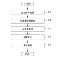
- 10 is a flowchart showing an example of a process flow of display control by the display device.
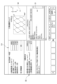
- 5A and 5B are diagrams illustrating examples of images displayed on a display unit by a display device.
- FIG. 11 is a functional block diagram of a display device for a machine tool according to a second embodiment.
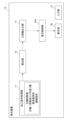
- FIG. 11 is a functional block diagram of a control system according to a third embodiment.
- FIG. 1 is a functional block diagram of a display device 1 of a machine tool according to the first embodiment.
- the display device 1 according to the first embodiment is a computer that displays various information of a machine tool that performs swing machining while swinging a cutting tool and a workpiece relative to one another on a display unit 20.
- the display device 1 is used, for example, by being connected to a control device (not shown) that is a computer that controls the machine tool.
- a machine tool processes a workpiece with a cutting tool by operating at least one spindle that rotates the cutting tool and the workpiece relative to one another, and at least one feed axis that moves the cutting tool relative to the workpiece.
- the machine tool performs various types of machining based on a machining program.
- the shape of the workpiece is not limited when machining with the machine tool according to this embodiment. In other words, it can be applied even when the workpiece has a tapered or arc-shaped portion on the machining surface, requiring multiple feed axes (Z-axis and X-axis), or when the workpiece is cylindrical or cylindrical and only one specific feed axis (Z-axis) is sufficient.
- the display device 1 is configured, for example, using a computer equipped with memories such as a ROM (read only memory) and a RAM (random access memory), a CPU (control processing unit), and a communication control unit, all connected to each other via a bus.
- the display device 1 also further comprises a display unit 20 that displays various information, and an input unit 21 into which an operator inputs various information.
- the display unit 20 is configured, for example, by a display that displays various information.
- the input unit 21 is, for example, an operating means such as a touch panel, keyboard, or button.
- the display device 1 of the machine tool may be configured as a CNC (Computer Numerical Controller) and may be connected to a higher-level computer (not shown) such as a CNC or a PLC (Programmable Logic Controller).
- a higher-level computer such as a CNC or a PLC (Programmable Logic Controller).
- machining conditions such as the rotation speed may be input to the display device 1 of the machine tool from the higher-level computer.
- the display device 1 has a processing condition acquisition unit 11, a calculation unit 12, an upper limit acquisition unit 13, an index output unit 14, and a display control unit 15 as its functional units. These functional units of the display device 1 are realized by the cooperation of the CPU, memory, and the control program stored in the memory.
- the machining condition acquisition unit 11 is a machining condition acquisition function that acquires machining conditions for performing oscillation machining.
- the machining conditions may be, for example, those input by an operator to the display device 1 via the input unit 21 or an external computer in accordance with the display on the display unit 20 of the display device 1, or may be those automatically acquired from the machining program, setting parameters of the machine tool, etc.
- the machining conditions include information necessary for machining, such as the spindle speed (1/min), the feed amount per spindle revolution (mm/rev), the command position of the feed axis, and the oscillation conditions.
- the feed amount per spindle revolution (mm/rev) may be calculated from a combination of the spindle speed (1/min) and the feed rate (mm/min) of the cutting tool.
- the oscillation conditions included in the processing conditions include at least a frequency parameter, which is information on the oscillation frequency of the cutting tool or the workpiece, and an amplitude parameter, which is information on the oscillation amplitude of the cutting tool or the workpiece, as information for uniquely identifying the vibration waveform.
- the frequency parameter may be the relative oscillation frequency per rotation of the cutting tool and the workpiece, or the oscillation frequency per unit time. It may also be a periodic parameter of the forward and backward movement.
- the amplitude parameter may be information on the oscillation amplitude with respect to the relative feed amount per rotation of the cutting tool and the workpiece, or a distance parameter of the forward and backward movement.
- These periodic parameters of the forward and backward movement and the distance parameter of the forward and backward movement may be determined from the forward speed, the backward speed, the forward distance, the backward distance, the spindle rotation speed, the control period, etc.
- the frequency parameter and the amplitude parameter may be determined from the spindle rotation speed, the feed rate per minute, the frequency magnification, which is the relative oscillation frequency per rotation of the cutting tool and the workpiece, and the amplitude magnification, which is the oscillation amplitude with respect to the relative feed amount per rotation of the cutting tool and the workpiece, etc.
- the frequency magnification and the amplitude magnification may be calculated based on the above-mentioned multiple conditions.
- the oscillation frequency multiplier I (times) indicating the oscillation frequency per rotation of the spindle is used as the frequency parameter.
- the oscillation frequency multiplier I (times) is directly specified by the operator via the input unit 21.
- the oscillation amplitude magnification K (times) is used as an amplitude parameter, which indicates the magnitude of the oscillation amplitude relative to the magnitude of the feed rate per rotation of the spindle.
- the oscillation amplitude magnification K (times) is also directly specified by the operator from the input unit 21.
- the values of the frequency magnification and amplitude magnification themselves may be obtained from input from an external computer, a machining program, or setting parameters.
- Whether or not air cutting is possible is determined by only two factors, the frequency magnification and the amplitude magnification, so by directly setting the two conditions, the frequency magnification and the amplitude magnification, as the conditions for oscillation cutting, it becomes easy to determine the conditions for air cutting, and so this setting method is common.
- the calculation unit 12 is a calculation function that calculates acceleration information including at least one of the acceleration and jerk of the feed axis of the oscillating operation based on the machining conditions. In this embodiment, the calculation unit 12 calculates both the acceleration and jerk using at least a frequency parameter and an amplitude parameter included in the machining conditions.
- the upper limit value acquisition unit 13 acquires the upper limit value of at least one of the acceleration and the jerk.
- the upper limit value may be stored in advance in the display device 1 as a parameter of the machine tool, for example, or may be input by the operator through the input unit 21.
- the index output unit 14 outputs indices of acceleration and jerk based on the acceleration information calculated by the calculation unit 12 and the upper limit value of acceleration and the upper limit value of jerk acquired by the upper limit value acquisition unit 13. In this embodiment, the index output unit 14 calculates the indices as a ratio of the upper limit values of acceleration and jerk calculated by the calculation unit 12. The index output unit 14 also outputs indices of acceleration and jerk based on the acceleration and jerk calculated by the calculation unit 12 and the upper limit values of acceleration and jerk acquired by the upper limit value acquisition unit 13. The index output unit 14 calculates the indices as a ratio of the upper limit values of acceleration and jerk calculated by the calculation unit 12. The ratio may be a percentage or a ratio.
- the index output unit 14 is not limited to a configuration that outputs an index using a numerical value such as a ratio.
- the index output unit 14 may output an index at multiple levels determined in advance, or may express the index using text or symbols rather than numerical values so that the degree of change can be distinguished.
- the display control unit 15 is a display control function that displays various information of the display device 1 and information on the operator's input results on the display unit 20.
- the display control unit 15 also executes display control that displays an image based on acceleration information on the display unit 20. In the display control, the ratio of acceleration and jerk to the upper limit is displayed on the display unit 20 as an image based on acceleration information.
- FIG. 2 is a flowchart showing an example of the process flow of display control by a display device. Note that the order and content of the processes shown in the flowchart are merely examples, and the order and content of the processes can be changed as appropriate.
- the machining condition acquisition unit 11 acquires machining conditions from the operator's input or from the machining program or machine tool parameters (step S11).
- the machining conditions acquired by the machining condition acquisition unit 11 include, for example, the spindle speed S (rev/min), the feed rate F (mm/rev), the oscillation frequency magnification I (times), the oscillation amplitude magnification K (times), etc.
- the calculation unit 12 calculates the acceleration and jerk as acceleration information based on the machining conditions acquired by the machining condition acquisition unit 11 (step S12).
- the machining condition acquisition unit 11 calculates the maximum acceleration and maximum jerk. Note that the acceleration and jerk calculated by the machining condition acquisition unit 11 are not limited to maximum values.
- the calculation unit 12 calculates the maximum acceleration based on the formula (1).
- the calculation unit 12 also calculates the maximum jerk based on the formula (2).
- a max indicates the maximum acceleration
- J max indicates the maximum jerk
- K indicates the oscillation amplitude magnification
- f indicates the feed amount
- S indicates the spindle rotation speed
- I indicates the oscillation frequency magnification.
- the upper limit acquisition unit 13 acquires the upper acceleration limit A up and the upper jerk limit J up that are set in advance from the memory unit of the display device 1, parameters of the control device or the machine tool, etc. (step S13).
- the index output unit 14 outputs an acceleration index indicating the degree of the maximum acceleration A max relative to the upper acceleration limit A up and a jerk index indicating the degree of the maximum jerk J max relative to the upper jerk limit J up (step S14).
- the index output unit 14 outputs YA, which is the ratio (proportion) of the maximum acceleration Amax to the upper acceleration limit Aup , as the acceleration index based on the formula (3).
- the index output unit 14 also outputs YJ, which is the ratio (proportion) of the maximum jerk Jmax to the upper jerk limit Jup , as the jerk index based on the formula (4).
- the display control unit 15 executes display control to display the acceleration information including the maximum acceleration A max and the maximum jerk J max on the display unit 20 as an image based on the acceleration information (step S15).
- FIG. 3 is a diagram showing an example of an image displayed on the display unit 20 by the display device 1.
- the image shown in FIG. 3 includes a program display 51 that shows the contents of the machining program, a tool path check display 52 that shows the machining path of the cutting tool, a condition display 53 that shows the machining conditions and the judgment results, and an acceleration information display 54 that displays information related to acceleration.
- condition display 53 includes the spindle speed S (rev/min), the feed rate F (mm/rev), the oscillation frequency magnification I (times), the oscillation amplitude magnification K (times), and information indicating whether air cutting is possible.
- the acceleration information display 54 indicates the maximum acceleration Amax , the maximum jerk Jmax , and the upper limit mechanical load rate (%).
- the upper limit mechanical load rate (%) is the ratio (proportion) of the maximum acceleration Amax to the upper acceleration limit value Aup , the ratio (proportion) of the maximum jerk Jmax to the upper jerk limit value Jup , or information calculated based on these ratios.
- the display device 1 for a machine tool that performs swing machining while swinging the cutting tool and the workpiece relative to one another provides the following effects:
- the display device 1 of the machine tool includes a machining condition acquisition unit 11 that acquires at least frequency parameters and amplitude parameters as machining conditions for performing oscillating machining, a calculation unit 12 that calculates acceleration information including the acceleration, jerk, or both of the oscillating motion based on at least the frequency parameters and the amplitude parameters, and a display control unit 15 that displays an image based on the acceleration information on the display unit 20.
- acceleration information including automatically calculated acceleration and jerk is displayed on the display unit 20, so the operator can easily grasp the forces acting on the machine tool through the acceleration and jerk.
- the machining condition acquisition unit 11 acquires the spindle speed, the feed rate per spindle rotation, the frequency multiplication factor as a frequency parameter which is the number of oscillations per spindle rotation, and the amplitude multiplication factor as an amplitude parameter which is the amplitude ratio to the feed rate per spindle rotation as machining conditions
- the calculation unit 12 calculates the acceleration information of the oscillation operation based on the spindle speed, the feed rate per spindle rotation, the frequency multiplication factor, and the amplitude multiplication factor.
- Whether or not air cutting is performed is determined by only two factors, the frequency multiplication factor and the amplitude multiplication factor, so by directly setting the two conditions, the frequency multiplication factor and the amplitude multiplication factor, as conditions for oscillation cutting, it is easy to determine the conditions for air cutting, and this setting method is common. On the other hand, it is even more complicated to calculate and check acceleration and jerk from the two factors, the frequency multiplication factor and the amplitude multiplication factor.
- the display device 1 of this embodiment also includes an upper limit value acquisition unit 13 that acquires upper limit values set for each of the acceleration and jerk, and an index output unit 14 that outputs an index indicating the degree of acceleration relative to the set upper limit value and an index indicating the degree of jerk relative to the set upper limit value, and the display control unit 15 displays the index on the display unit 20.
- an upper limit value acquisition unit 13 that acquires upper limit values set for each of the acceleration and jerk
- an index output unit 14 that outputs an index indicating the degree of acceleration relative to the set upper limit value and an index indicating the degree of jerk relative to the set upper limit value
- the display control unit 15 displays the index on the display unit 20.
- an index is output that indicates the magnitude relationship between the force applied to the machine, such as acceleration and jerk based on the machining conditions, and the upper limit value.
- the operator can intuitively grasp the degree of shaking based on the index.
- a display device 1A according to a second embodiment which has a different configuration from the display device 1 according to the first embodiment, will be described with reference to Fig. 4.
- Fig. 4 is a functional block diagram of the display device 1A for a machine tool according to the second embodiment.
- the same reference numerals may be used to designate configurations similar to or common to the above embodiment, and detailed description thereof may be omitted.
- the display device 1A of the second embodiment includes a processing condition acquisition unit 11, a calculation unit 12, a force information output unit 17, and a display control unit 15A as functional units.
- the display device 1A of the second embodiment is configured with the same hardware as the display device 1 of the first embodiment.
- the force information output unit 17 acquires the weight and inertia of the cutting tool of the machine tool and the workpiece as mass parameters.
- the weight and inertia may be stored in advance in a storage unit (not shown) of the display device 1A, or may be input by the operator according to the display screen of the display unit 20.
- the force information output unit 17 outputs the force or torque applied to the machine tool as force information based on the acceleration information including the acceleration calculated by the calculation unit 12 and the weight or inertia.
- the display control unit 15A displays an image including force information based on the acceleration information on the display unit 20.
- the force information may be only force or torque, or both. It may also be displayed including weight and inertia.
- the display control unit 15A may also execute display control to display an image including the acceleration or jerk, or weight and inertia, which are the original data used for the calculation, together with the force information on the display unit 20.
- the display device 1A of the second embodiment further includes a force information output unit 17 that acquires mass parameters including mass, inertia, or both, and outputs the force, torque, or both of the swinging motion based on the mass parameters and acceleration information, and the display control unit 15A displays the force, torque, or both of the swinging motion on the display unit 20. This makes it possible to confirm the numerical values of the force and torque generated by the swinging motion, and directly grasp the load on the machine tool.
- a control system 100 including a control device 2 and a display device 1B for a machine tool that performs swing machining while swinging a cutting tool and a workpiece relative to each other will be described with reference to Fig. 5.
- Fig. 5 is a functional block diagram of the control system 100 according to the third embodiment.
- the control device 2 of the control system 100 is a computer that controls a machine tool that performs machining while moving a cutting tool and a workpiece relative to each other.
- the configuration of the machine tool is the same as in the first embodiment.
- the control device 2 is configured using a computer equipped with memories such as ROM and RAM, a CPU, a communication control unit, and a display screen such as a display, which are connected to each other via a bus, for example.
- the control device 2 of the machine tool may be configured as a CNC, and may be connected to a higher-level computer (not shown) such as a CNC or PLC.
- machining conditions such as rotation speed may be input to the control device 2 of the machine tool from the higher-level computer.
- the control device 2 includes, as functional units, a processing condition acquisition unit 11, a swing motion generation unit 25, and a drive control unit 30. These functional units of the control device 2 are realized by the cooperation of the CPU, memory, and the control program stored in the memory.
- the machining condition acquisition unit 11 has the same function as the machining condition acquisition unit 11 of the first embodiment.
- the swing motion generation unit 25 generates a swing motion based on the machining conditions acquired by the machining condition acquisition unit 11. Note that the acceleration generated by the swing motion generation unit 25 may be generated taking into account factors other than the machining conditions.
- the drive control unit 30 is an axis control function that, when it receives a rocking motion generated by the rocking motion generation unit 25 from the rocking motion generation unit 25, controls the motion axis based on the content of the rocking motion.
- the display device 1B includes a calculation unit 12 and a display control unit 15B as functional units.
- the hardware configuration of the display device 1B is the same as that of the display device 1 of the first embodiment, and these functional units of the display device 1B are realized by the cooperation of a CPU, a memory, and a control program stored in the memory.
- the calculation unit 12 has the same functions as the calculation unit 12 of the first embodiment.
- the display control unit 15B executes display control to display an image including the acceleration and jerk calculated by the calculation unit 12 on the display unit 20 while the swing operation is being controlled by the drive control unit 30.
- the display control unit 15B may display the maximum acceleration and maximum jerk, or may display the acceleration and jerk that change sequentially in real time.
- the control system 100 of the third embodiment includes a processing condition acquisition unit 11 arranged in the control device 2 and configured to acquire at least frequency parameters and amplitude parameters as processing conditions for performing oscillation processing, a swing motion generation unit 25 arranged in the control device 2 and configured to generate an oscillation motion based on the processing conditions, a drive control unit 30 arranged in the control device 2 and configured to control the motion axis based on the oscillation motion generated by the swing motion generation unit 25, a calculation unit 12 arranged in the display device 1B and configured to calculate acceleration information including the acceleration, jerk, or both of the oscillation motion based on at least the frequency parameters and the amplitude parameters, and a display control unit 15 arranged in the display device 1B and configured to display an image based on the acceleration information on the display unit 20 during the oscillation motion by the drive control unit 30.
- a processing condition acquisition unit 11 arranged in the control device 2 and configured to acquire at least frequency parameters and amplitude parameters as processing conditions for performing oscillation processing
- a swing motion generation unit 25 arranged in the
- the calculation unit 12 is disposed on the display device 1B side, but the position of the calculation unit 12 is not limited to the display device 1B.
- the calculation unit 12 may be disposed on the control device 2.
- the machining condition acquisition unit 11 directly acquires the four items of spindle speed S (rev/min), feed amount F (mm/rev), oscillation frequency magnification I (times), and oscillation amplitude magnification K (times), but this configuration is not limited to this.
- the machining condition acquisition unit 11 may be configured to indirectly acquire the spindle speed S (rev/min), feed amount F (mm/rev), oscillation frequency magnification I (times), and oscillation amplitude magnification K (times) by calculating them from other information.
- the display device and control device may be configured as an integrated single computer.
- the processing condition acquisition unit (11) The machining conditions include a spindle rotation speed, a feed amount per one spindle rotation, a frequency magnification as the frequency parameter which is the number of oscillations per one spindle rotation, and an amplitude magnification as the amplitude parameter which is an amplitude ratio to the feed amount per one spindle rotation;
- the calculation unit (12) The acceleration information of the swing motion is calculated based on the spindle rotation speed, the feed amount per rotation of the spindle, the frequency magnification, and the amplitude magnification.
- an upper limit value acquisition unit (13) that acquires an upper limit value set for the acceleration or the jerk
- an index output unit (14) that outputs an index indicating a degree of the acceleration with respect to the set upper limit value, or a degree of the jerk with respect to the set upper limit value
- the display control unit (15) displays the indicator on the display unit (20).
- a force information output unit (17) that acquires a mass parameter including a mass, an inertia, or both of them, and outputs a force, a torque, or both of them of a swinging motion based on the mass parameter and the acceleration information
- the display control unit (15A) displays the force of the rocking motion, the torque, or both of them on the display unit (20).
- a calculation unit that is disposed in the display device (1B) or the control device (2) and calculates acceleration information including an acceleration, a jerk, or both of the acceleration and the jerk of a swinging motion based on at least the frequency parameter and the amplitude parameter; and a display control unit (15) arranged in the display device (1B)
Landscapes
- Engineering & Computer Science (AREA)
- Physics & Mathematics (AREA)
- Human Computer Interaction (AREA)
- Manufacturing & Machinery (AREA)
- General Physics & Mathematics (AREA)
- Automation & Control Theory (AREA)
- Mechanical Engineering (AREA)
- Geometry (AREA)
- Machine Tool Sensing Apparatuses (AREA)
- Numerical Control (AREA)
- Automatic Control Of Machine Tools (AREA)
Priority Applications (4)
| Application Number | Priority Date | Filing Date | Title |
|---|---|---|---|
| PCT/JP2023/017815 WO2024232102A1 (ja) | 2023-05-11 | 2023-05-11 | 工作機械の表示装置及び制御システム |
| CN202380097153.XA CN121100313A (zh) | 2023-05-11 | 2023-05-11 | 机床的显示装置以及控制系统 |
| JP2025519301A JPWO2024232102A1 (cg-RX-API-DMAC7.html) | 2023-05-11 | 2023-05-11 | |
| DE112023005893.8T DE112023005893T5 (de) | 2023-05-11 | 2023-05-11 | Anzeigevorrichtung und Steuerungssystem für Werkzeugmaschinen |
Applications Claiming Priority (1)
| Application Number | Priority Date | Filing Date | Title |
|---|---|---|---|
| PCT/JP2023/017815 WO2024232102A1 (ja) | 2023-05-11 | 2023-05-11 | 工作機械の表示装置及び制御システム |
Publications (1)
| Publication Number | Publication Date |
|---|---|
| WO2024232102A1 true WO2024232102A1 (ja) | 2024-11-14 |
Family
ID=93430039
Family Applications (1)
| Application Number | Title | Priority Date | Filing Date |
|---|---|---|---|
| PCT/JP2023/017815 Ceased WO2024232102A1 (ja) | 2023-05-11 | 2023-05-11 | 工作機械の表示装置及び制御システム |
Country Status (4)
| Country | Link |
|---|---|
| JP (1) | JPWO2024232102A1 (cg-RX-API-DMAC7.html) |
| CN (1) | CN121100313A (cg-RX-API-DMAC7.html) |
| DE (1) | DE112023005893T5 (cg-RX-API-DMAC7.html) |
| WO (1) | WO2024232102A1 (cg-RX-API-DMAC7.html) |
Citations (3)
| Publication number | Priority date | Publication date | Assignee | Title |
|---|---|---|---|---|
| JP2019028597A (ja) * | 2017-07-27 | 2019-02-21 | ファナック株式会社 | 揺動切削を行う工作機械の制御装置 |
| WO2022181594A1 (ja) * | 2021-02-26 | 2022-09-01 | ファナック株式会社 | 計算装置 |
| WO2023007678A1 (ja) * | 2021-07-29 | 2023-02-02 | ファナック株式会社 | 工作機械の制御装置及び工作機械の制御システム |
-
2023
- 2023-05-11 DE DE112023005893.8T patent/DE112023005893T5/de active Pending
- 2023-05-11 JP JP2025519301A patent/JPWO2024232102A1/ja active Pending
- 2023-05-11 WO PCT/JP2023/017815 patent/WO2024232102A1/ja not_active Ceased
- 2023-05-11 CN CN202380097153.XA patent/CN121100313A/zh active Pending
Patent Citations (3)
| Publication number | Priority date | Publication date | Assignee | Title |
|---|---|---|---|---|
| JP2019028597A (ja) * | 2017-07-27 | 2019-02-21 | ファナック株式会社 | 揺動切削を行う工作機械の制御装置 |
| WO2022181594A1 (ja) * | 2021-02-26 | 2022-09-01 | ファナック株式会社 | 計算装置 |
| WO2023007678A1 (ja) * | 2021-07-29 | 2023-02-02 | ファナック株式会社 | 工作機械の制御装置及び工作機械の制御システム |
Also Published As
| Publication number | Publication date |
|---|---|
| CN121100313A (zh) | 2025-12-09 |
| DE112023005893T5 (de) | 2025-12-18 |
| JPWO2024232102A1 (cg-RX-API-DMAC7.html) | 2024-11-14 |
Similar Documents
| Publication | Publication Date | Title |
|---|---|---|
| JP4648471B2 (ja) | 工作機械の工具軌跡表示装置 | |
| TWI570532B (zh) | 數値控制裝置 | |
| JP5582240B1 (ja) | モータの最適動作パターン選定方法、モータの最適動作パターン選定プログラム及びモータ選定装置 | |
| JP7252426B1 (ja) | 工作機械の制御装置及び工作機械の表示装置 | |
| JP6843314B1 (ja) | 数値制御装置、数値制御方法および機械学習装置 | |
| WO2022181594A1 (ja) | 計算装置 | |
| CN104932419A (zh) | 使用手动操作工作机械的模拟装置 | |
| US6895297B2 (en) | Numerical control device | |
| JP2022149202A (ja) | ロボットの制御プログラムの生成方法、ロボットの制御プログラムを生成する処理をプロセッサーに実行させるコンピュータープログラム、及び教示装置 | |
| WO2024232102A1 (ja) | 工作機械の表示装置及び制御システム | |
| JP2762788B2 (ja) | 移動体の動作表示装置及びその表示方法 | |
| JPWO2020261473A1 (ja) | 数値制御装置、機械学習装置、及び数値制御方法 | |
| JP4639058B2 (ja) | ねじ切り加工装置 | |
| WO2023007678A1 (ja) | 工作機械の制御装置及び工作機械の制御システム | |
| US6842651B1 (en) | Programmable controller having plural speed pattern generators | |
| JP2000235411A (ja) | 加工情報を用いた数値制御装置 | |
| JP2009223354A (ja) | アラーム情報を表示する機能を有する数値制御装置 | |
| WO2024232103A1 (ja) | 工作機械の表示装置 | |
| CN106843163A (zh) | 一种数控系统、控制方法及控制装置 | |
| WO2024232099A1 (ja) | 計算装置 | |
| WO2024232104A1 (ja) | 工作機械の表示装置及びプログラム | |
| JP6471446B2 (ja) | ロボット操作装置、ロボットシステム、及びロボット操作プログラム | |
| WO2023181301A9 (ja) | 表示装置およびコンピュータ読み取り可能な記憶媒体 | |
| US20210268656A1 (en) | Method for controlling drives of a robot, and robot system | |
| JP7827878B2 (ja) | 工作機械の制御装置及び工作機械の表示装置 |
Legal Events
| Date | Code | Title | Description |
|---|---|---|---|
| 121 | Ep: the epo has been informed by wipo that ep was designated in this application |
Ref document number: 23936650 Country of ref document: EP Kind code of ref document: A1 |
|
| ENP | Entry into the national phase |
Ref document number: 2025519301 Country of ref document: JP Kind code of ref document: A |
|
| WWE | Wipo information: entry into national phase |
Ref document number: 2025519301 Country of ref document: JP |
|
| WWE | Wipo information: entry into national phase |
Ref document number: 112023005893 Country of ref document: DE |
|
| WWP | Wipo information: published in national office |
Ref document number: 112023005893 Country of ref document: DE |