WO2024232002A1 - 内燃機関の制御装置 - Google Patents
内燃機関の制御装置 Download PDFInfo
- Publication number
- WO2024232002A1 WO2024232002A1 PCT/JP2023/017384 JP2023017384W WO2024232002A1 WO 2024232002 A1 WO2024232002 A1 WO 2024232002A1 JP 2023017384 W JP2023017384 W JP 2023017384W WO 2024232002 A1 WO2024232002 A1 WO 2024232002A1
- Authority
- WO
- WIPO (PCT)
- Prior art keywords
- angle
- angular velocity
- interval
- section
- ideal
- Prior art date
- Legal status (The legal status is an assumption and is not a legal conclusion. Google has not performed a legal analysis and makes no representation as to the accuracy of the status listed.)
- Ceased
Links
Images










Classifications
-
- F—MECHANICAL ENGINEERING; LIGHTING; HEATING; WEAPONS; BLASTING
- F02—COMBUSTION ENGINES; HOT-GAS OR COMBUSTION-PRODUCT ENGINE PLANTS
- F02D—CONTROLLING COMBUSTION ENGINES
- F02D45/00—Electrical control not provided for in groups F02D41/00 - F02D43/00
Definitions
- This application relates to a control device for an internal combustion engine.
- Patent Document 1 is configured to calculate the crank angular velocity and crank angular acceleration based on the output signal of the crank angle sensor, calculate the gas pressure torque generated by combustion based on the crank angular velocity and crank angular acceleration, and calculate the amount of work due to the gas pressure torque.
- the crank angular acceleration includes an acceleration component due to the external load torque applied to the crankshaft from outside the internal combustion engine. Therefore, unless the gas pressure torque is calculated based on the crank angular velocity and crank angular acceleration after grasping the external load torque, the calculation accuracy will decrease. For this reason, it is possible to estimate the external load torque based on the crank angular velocity, etc. However, if the crank angular velocity, etc. fluctuates due to manufacturing errors in the teeth of the detection part detected by the crank angle sensor, the estimation accuracy of the external load torque will deteriorate.
- the present application aims to provide a control device for an internal combustion engine that can accurately estimate external load torque even if the crank angular velocity, etc., fluctuates due to variations in the teeth of the detection part, etc.
- the control device for an internal combustion engine is a control device for an internal combustion engine, the control device for an internal combustion engine including a plurality of detection targets provided at a plurality of predetermined crank angles on a rotating member that rotates integrally with a crankshaft, a specific crank angle sensor that is fixed to a non-rotating member and detects the detection targets, and a gas pressure sensor that detects a gas pressure in an intake pipe, an angle information detection unit that detects a crank angle and a detection time when the crank angle is detected based on an output signal of the specific crank angle sensor, calculates an angle interval corresponding to an angle section between the detected angles based on the detected crank angle, and calculates a time interval corresponding to the angle section based on the detection time; an angle information correction unit that corrects the angle interval or the time interval of each of the angle sections by a correction value provided corresponding to each of the angle sections; an intake pipe gas pressure detection unit that detects a gas pressure in the intake pipe based on an output signal of the gas pressure sensor;
- an estimated value of the first axial torque due to the gas pressure in the cylinder and the reciprocating motion of the piston is estimated using a physical model equation of the crank mechanism based on the detected value of the gas pressure in the intake pipe and the detected angle, and a first ideal section angular velocity in a first ideal state in which it is assumed that there is no angular variation in the multiple detected parts and no external load torque is calculated based on the estimated value of the first axial torque and the moment of inertia of the crankshaft system.
- a detection section angular velocity that reflects the effects of the angular variation in the multiple detected parts and the external load torque is calculated based on the output signal of a specific crank angle sensor.
- the detection section angular velocity fluctuates due to the angular variation in the multiple detected parts and the setting error of the correction value, etc. Therefore, the instantaneous difference between the first ideal section angular velocity and the detection section angular velocity is affected greatly by the fluctuation in the detection section angular velocity, and the external load torque cannot be accurately estimated.
- the difference between the average value of the detection section angular velocity and the average value of the first ideal section angular velocity in the average processing angle section is used, so the effect of fluctuations in the detection section angular velocity is smoothed, allowing the external load torque to be estimated with high accuracy.
- FIG. 1 is a schematic configuration diagram of an internal combustion engine and a control device according to a first embodiment.
- 1 is a schematic configuration diagram of an internal combustion engine and a control device according to a first embodiment.
- FIG. 2 is a block diagram of a control device according to the first embodiment.
- FIG. 2 is a hardware configuration diagram of a control device according to the first embodiment.
- 4 is a time chart for explaining an angle information detection process according to the first embodiment.
- 5 is a diagram for explaining correction values stored in a storage device according to the first embodiment;
- FIG. 5 is a time chart for illustrating a process for calculating a crank acceleration and an angular acceleration according to the first embodiment.
- 5 is a diagram for explaining a process of a first ideal angular velocity calculation unit according to the first embodiment.
- FIG. 5 is a diagram for explaining the estimation principle of an external load torque according to the first embodiment.
- FIG. 5 is a diagram for explaining the estimation principle of an external load torque according to the first embodiment.
- FIG. 5 is a diagram for explaining the estimation principle of an external load torque according to the first embodiment.
- FIG. 5 is a diagram for explaining estimation of an external load torque according to the first embodiment.
- FIG. 10 is a diagram for explaining fluctuations in crank angular velocity when the correction process according to the first embodiment is not performed.
- FIG. 10 is a diagram for explaining fluctuations in crank angular velocity when the correction process according to the first embodiment is not performed.
- FIG. 6 is a diagram for explaining a process of a second ideal angular velocity calculation unit according to the first embodiment.
- FIG. 10A to 10C are diagrams for explaining the behavior of the crank angular velocity when the correction process according to the first embodiment is not performed.
- 5A to 5C are diagrams for explaining the behavior of the crank angular velocity when the correction process according to the first embodiment is performed.
- 5 is a diagram for explaining fluctuations in crank angular velocity when performing correction processing according to the first embodiment.
- FIG. 13 is a diagram for explaining a process of a first ideal angular velocity calculation unit according to the second embodiment.
- FIG. 13 is a diagram for explaining a process of a second ideal angular velocity calculation unit according to the second embodiment.
- FIG. 13 is a diagram for explaining the processing of a correction value changing unit according to the third embodiment.
- FIG. 1 A control device 50 for an internal combustion engine 1 according to a first embodiment (hereinafter simply referred to as the control device 50) will be described with reference to the drawings.
- Figures 1 and 2 are schematic configuration diagrams of the internal combustion engine 1 and the control device 50 according to this embodiment
- Figure 3 is a block diagram of the control device 50 according to this embodiment.
- the internal combustion engine 1 and the control device 50 are mounted on a vehicle, and the internal combustion engine 1 serves as a driving force source for the vehicle (wheels).
- the internal combustion engine 1 has a cylinder 7 that burns a mixture of air and fuel.
- the internal combustion engine 1 has an intake passage 23 that supplies air to the cylinder 7, and an exhaust passage 17 that discharges exhaust gas burned in the cylinder 7.
- the internal combustion engine 1 is a gasoline engine.
- the internal combustion engine 1 has a throttle valve 4 that opens and closes the intake passage 23.
- the throttle valve 4 is an electronically controlled throttle valve that is driven to open and close by an electric motor controlled by a control device 50.
- the throttle valve 4 is provided with a throttle opening sensor 19 that outputs an electric signal according to the opening of the throttle valve 4.
- the intake passage 23 upstream of the throttle valve 4 is provided with an airflow sensor 3 that outputs an electrical signal according to the amount of intake air drawn into the intake passage 23.
- the internal combustion engine 1 is provided with an exhaust gas recirculation device 20.
- the exhaust gas recirculation device 20 has an EGR flow path 21 that recirculates exhaust gas from the exhaust passage 17 to the intake manifold 12, and an EGR valve 22 that opens and closes the EGR flow path 21.
- the intake manifold 12 is the part of the intake passage 23 downstream of the throttle valve 4.
- the EGR valve 22 is an electronically controlled EGR valve that is driven to open and close by an electric motor controlled by the control device 50.
- the exhaust passage 17 is provided with an air-fuel ratio sensor 18 that outputs an electrical signal according to the air-fuel ratio of the exhaust gas in the exhaust passage 17.
- the intake manifold 12 is provided with a gas pressure sensor 8 that outputs an electrical signal corresponding to the pressure inside the intake manifold 12.
- An injector 13 that injects fuel is provided in the downstream portion of the intake manifold 12. The injector 13 may be provided so as to inject fuel directly into the cylinder 7.
- the internal combustion engine 1 is provided with an atmospheric pressure sensor 33 that outputs an electrical signal corresponding to the atmospheric pressure.
- the intake valve 14 is provided with an intake variable valve timing mechanism that varies the valve opening and closing timing.
- the exhaust valve 15 is provided with an exhaust variable valve timing mechanism that varies the valve opening and closing timing.
- the variable valve timing mechanisms 14 and 15 have electric actuators.
- the internal combustion engine 1 has a number of cylinders 7 (three in this example). Each cylinder 7 has a piston 5 inside. The piston 5 of each cylinder 7 is connected to the crankshaft 2 via a connecting rod 9 and a crank 32. The crankshaft 2 is rotationally driven by the reciprocating motion of the piston 5. The combustion gas pressure generated in each cylinder 7 presses against the top surface of the piston 5, and rotates the crankshaft 2 via the connecting rod 9 and the crank 32.
- the crankshaft 2 is connected to a power transmission mechanism that transmits driving force to the wheels.
- the power transmission mechanism is composed of a transmission, a differential gear, etc. Note that a vehicle equipped with the internal combustion engine 1 may be a hybrid vehicle equipped with a motor generator in the power transmission mechanism.
- the internal combustion engine 1 is equipped with a signal plate 10 that rotates integrally with the crankshaft 2.
- the signal plate 10 has multiple teeth at multiple predetermined crank angles.
- the signal plate 10 has teeth arranged at 10 degree intervals.
- the teeth of the signal plate 10 have missing teeth.
- the internal combustion engine 1 is equipped with a first crank angle sensor 11 that is fixed to the engine block 24 and detects the teeth of the signal plate 10.
- the internal combustion engine 1 is equipped with a camshaft 29 connected to the crankshaft 2 by a chain 28.
- the camshaft 29 drives the intake valve 14 and the exhaust valve 15 to open and close.
- the camshaft 29 rotates once while the crankshaft 2 rotates twice.
- the internal combustion engine 1 is equipped with a cam signal plate 31 that rotates together with the camshaft 29.
- the cam signal plate 31 has a number of teeth at a number of predetermined camshaft angles.
- the internal combustion engine 1 is equipped with a cam angle sensor 30 that is fixed to the engine block 24 and detects the teeth of the cam signal plate 31.
- the control device 50 detects the crank angle based on the top dead center of each piston 5 and determines the stroke of each cylinder 7 based on two types of output signals from the first crank angle sensor 11 and the cam angle sensor 30.
- the internal combustion engine 1 is a four-stroke engine with an intake stroke, a compression stroke, a combustion stroke, and an exhaust stroke.
- the internal combustion engine 1 is equipped with a flywheel 27 that rotates integrally with the crankshaft 2.
- the outer periphery of the flywheel 27 is the ring gear 25, which has multiple teeth at multiple predetermined crank angles.
- the teeth of the ring gear 25 are arranged at equal angular intervals in the circumferential direction. In this example, 60 teeth are provided at intervals of 6 degrees.
- the teeth of the ring gear 25 are not missing teeth.
- the internal combustion engine 1 is equipped with a second crank angle sensor 6 that is fixed to the engine block 24 and detects the teeth of the ring gear 25.
- the second crank angle sensor 6 is arranged radially outside the ring gear 25, facing the ring gear 25 with a gap between them.
- the side of the flywheel 27 opposite the crankshaft 2 is connected to a power transmission mechanism. Therefore, the output torque of the internal combustion engine 1 is transmitted to the wheels through the flywheel 27.
- the first crank angle sensor 11, cam angle sensor 30, and second crank angle sensor 6 output an electrical signal according to the change in distance between each sensor and the teeth due to the rotation of the crankshaft 2.
- the output signal of each angle sensor 11, 30, 6 is a square wave that turns on and off depending on whether the sensor is close to the teeth or far away.
- Each angle sensor 11, 30, 6 is, for example, an electromagnetic pickup type sensor.
- the flywheel 27 (ring gear 25) has a greater number of teeth than the signal plate 10 and is free of any missing teeth, allowing for high-resolution angle detection.
- the flywheel 27 also has a greater mass than the signal plate 10, suppressing high-frequency vibrations, allowing for high-precision angle detection.
- the second crank angle sensor 6 corresponds to the "specific crank angle sensor” in this application
- the flywheel 27 corresponds to the “rotating member” in this application
- the teeth of the ring gear 25 provided on the flywheel 27 correspond to the "detected part” in this application
- the engine block 24 corresponds to the "non-rotating member” in this application.
- the control device 50 is a control device that controls the internal combustion engine 1.
- the control device 50 includes control units such as an intake pipe gas pressure detection unit 51, an angle information detection unit 52, an angle information correction unit 53, an average interval setting unit 54, a one-revolution time detection unit 55, a first shaft torque estimation unit 56, a first ideal angular velocity calculation unit 57, a detection interval angular velocity calculation unit 58, an ideal average value calculation unit 59, a detection average value calculation unit 60, an external load torque estimation unit 61, a second shaft torque estimation unit 62, a second ideal angular velocity calculation unit 63, a correction value change unit 64, and an abnormality determination unit 65.
- control units such as an intake pipe gas pressure detection unit 51, an angle information detection unit 52, an angle information correction unit 53, an average interval setting unit 54, a one-revolution time detection unit 55, a first shaft torque estimation unit 56, a first ideal angular velocity calculation unit 57, a detection interval angular velocity calculation unit 58, an ideal average
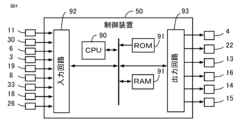
- control device 50 includes, as processing circuits, a calculation processing device 90 (computer) such as a CPU (Central Processing Unit), a memory device 91 connected to the calculation processing device 90 via a signal line such as a bus, an input circuit 92 that inputs external signals to the calculation processing device 90, and an output circuit 93 that outputs signals from the calculation processing device 90 to the outside.
- a calculation processing device 90 computer
- CPU Central Processing Unit
- memory device 91 connected to the calculation processing device 90 via a signal line such as a bus
- input circuit 92 that inputs external signals to the calculation processing device 90
- output circuit 93 that outputs signals from the calculation processing device 90 to the outside.
- the arithmetic processing device 90 may be an ASIC (Application Specific Integrated Circuit), an IC (Integrated Circuit), a DSP (Digital Signal Processor), an FPGA (Field Programmable Gate Array), various logic circuits, and various signal processing circuits.
- ASIC Application Specific Integrated Circuit
- IC Integrated Circuit
- DSP Digital Signal Processor
- FPGA Field Programmable Gate Array
- various logic circuits and various signal processing circuits.
- multiple arithmetic processing devices 90 of the same type or different types may be provided, and each process may be shared and executed.
- the memory device 91 includes volatile and non-volatile memory devices such as RAM (Random Access Memory), ROM (Read Only Memory), and EEPROM (Electrically Erasable Programmable ROM).
- the input circuit 92 is connected to various sensors and switches and includes A/D converters and the like that input the output signals of these sensors and switches to the arithmetic processing device 90.
- the output circuit 93 is connected to electrical loads and includes drive circuits and the like that output control signals from the arithmetic processing device 90 to these electrical loads.
- control units 51 to 65 of the control device 50 are realized by the arithmetic processing device 90 executing software (programs) stored in a storage device 91 such as a ROM or EEPROM, and working in cooperation with other hardware of the control device 50 such as the storage device 91, input circuit 92, and output circuit 93.
- the setting data of the moment of inertia Icrk and judgment values used by the control units 51 to 65 are stored in the storage device 91 such as a ROM or EEPROM.
- the data of the calculated values and detected values of the correction value Kc, angle interval ⁇ d, time interval ⁇ Td, first shaft torque estimate value Tcrke1, first ideal interval angular velocity ⁇ id1, detection interval angular velocity ⁇ sd, and external load torque Tload calculated by the control units 51 to 65 are stored in a rewritable storage device 91 such as a RAM.
- the input circuit 92 is connected to the first crank angle sensor 11, the cam angle sensor 30, the second crank angle sensor 6, the airflow sensor 3, the throttle opening sensor 19, the gas pressure sensor 8, the atmospheric pressure sensor 33, the air-fuel ratio sensor 18, and the accelerator position sensor 26.
- the output circuit 93 is connected to the throttle valve 4 (electric motor), the EGR valve 22 (electric motor), the injector 13, the ignition coil 16, the intake variable valve timing mechanism 14, and the exhaust variable valve timing mechanism 15.
- various sensors, switches, actuators, etc. are connected to the control device 50.
- the control device 50 detects the operating state of the internal combustion engine 1, such as the intake air volume, the pressure in the intake manifold, the atmospheric pressure, the air-fuel ratio, and the accelerator opening, based on the output signals of the various sensors.
- the control device 50 calculates the fuel injection amount, ignition timing, etc. based on the output signals of various sensors inputted, and drives and controls the injector 13 and the ignition coil 16, etc.
- the control device 50 calculates the output torque of the internal combustion engine 1 requested by the driver based on the output signal of the accelerator position sensor 26, etc., and controls the throttle valve 4, etc. so that the intake air volume realizes the requested output torque.
- the control device 50 calculates the target throttle opening, and drives and controls the electric motor of the throttle valve 4 so that the throttle opening detected based on the output signal of the throttle opening sensor 19 approaches the target throttle opening.
- the control device 50 also calculates the target opening of the EGR valve 22 based on the output signals of various sensors inputted, and drives and controls the electric motor of the EGR valve 22.
- the control device 50 calculates the target opening and closing timing of the intake valve and the target opening and closing timing of the exhaust valve based on the output signals of various sensors input, and controls the operation of the intake and exhaust variable valve timing mechanisms 14, 15 based on each target opening and closing timing.
- the intake pipe gas pressure detection unit 51 detects the gas pressure Pind in the intake pipe based on the output signal of the gas pressure sensor 8. The gas pressure Pind in the intake pipe is detected at every predetermined detection period.
- the angle information detection unit 52 detects the crank angle ⁇ d based on the output signal of the second crank angle sensor 6 designated as the specific crank angle sensor, and detects the detection time Td at which the crank angle ⁇ d is detected. Then, the angle information detection unit 52 calculates an angle interval ⁇ d corresponding to an angle section Sd between the detected angles ⁇ d based on the detected crank angle ⁇ d, and calculates a time interval ⁇ Td corresponding to the angle section Sd based on the detection time Td.
- the angle information detection unit 52 is configured to determine the crank angle ⁇ d when the falling edge (or rising edge) of the output signal (rectangular wave) of the second crank angle sensor 6 is detected.
- the angle information detection unit 52 determines a base falling edge, which is a falling edge corresponding to a base angle (for example, 0 degrees, which is the top dead center of the piston 5 of the first cylinder 7), and determines the crank angle ⁇ d corresponding to the number n of the falling edge counted up from the base falling edge (hereinafter referred to as angle identification number n).
- angle identification number n For example, when the angle information detection unit 52 detects a base falling edge, it sets the crank angle ⁇ d to the base angle (for example, 0 degrees) and sets the angle identification number n to 1.
- each time the angle information detection unit 52 detects a falling edge it increases the crank angle ⁇ d by a preset angle interval ⁇ d (6 degrees in this example) and increases the angle identification number n by one.
- the angle information detection unit 52 may be configured to read out the crank angle ⁇ d corresponding to the current angle identification number n using an angle table in which the relationship between the angle identification number n and the crank angle ⁇ d is preset.
- the angle information detection unit 52 associates the crank angle ⁇ d (detected angle ⁇ d) with the angle identification number n. After the maximum number (60 in this example), the angle identification number n returns to 1.
- the detection time Td and detection angle ⁇ d in which the missing tooth portion is complemented with information before and after the missing tooth portion may be used, or the detection time Td and detection angle ⁇ d in which the missing tooth portion is not complemented may be used as is. If the missing tooth portion is not complemented, the angle interval ⁇ d corresponding to the missing tooth portion is used in each calculation.
- the angle information detection unit 52 determines the base point falling edge of the second crank angle sensor 6 by referring to the reference crank angle ⁇ r detected based on the first crank angle sensor 11 and the cam angle sensor 30, which will be described later. For example, the angle information detection unit 52 determines that the falling edge of the reference crank angle ⁇ r at the time when the falling edge of the second crank angle sensor 6 is detected is closest to the base point angle, as the base point falling edge.
- the angle information detection unit 52 also refers to the stroke of each cylinder 7 determined based on the first crank angle sensor 11 and the cam angle sensor 30 to determine the stroke of each cylinder 7 corresponding to the crank angle ⁇ d.
- the angle information detection unit 52 detects the detection time Td when it detects the falling edge of the output signal (rectangular wave) of the second crank angle sensor 6, and associates the detection time Td with the angle identification number n. Specifically, the angle information detection unit 52 detects the detection time Td using a timer function provided in the calculation processing device 90.
- the angle information detection unit 52 when the angle information detection unit 52 detects a falling edge, it sets the angle interval between the detection angle ⁇ d(n) corresponding to the current angle identification number (n) and the detection angle ⁇ d(n-1) corresponding to the previous angle identification number (n-1) to the angle interval Sd(n) corresponding to the current angle identification number (n).
- the angle information detection unit 52 when the angle information detection unit 52 detects a falling edge, it calculates the deviation between the detection angle ⁇ d(n) corresponding to the current angle identification number (n) and the detection angle ⁇ d(n-1) corresponding to the previous angle identification number (n-1), and sets this as the angle interval ⁇ d(n) corresponding to the current angle identification number (n) (current angle interval Sd(n)).
- the angular intervals of the teeth of the ring gear 25 are all equal, so the angle information detection unit 52 sets the angular intervals ⁇ d of all angle identification numbers n to a preset angle (6 degrees in this example).
- the angle information detection unit 52 when the angle information detection unit 52 detects a falling edge, it calculates the deviation between the detection time Td(n) corresponding to the current angle identification number (n) and the detection time Td(n-1) corresponding to the previous angle identification number (n-1), and sets this as the time interval ⁇ Td(n) corresponding to the current angle identification number (n) (current angle interval Sd(n)).
- the angle information detection unit 52 detects the reference crank angle ⁇ r based on the top dead center of the piston 5 of the first cylinder 7 based on two types of output signals from the first crank angle sensor 11 and the cam angle sensor 30, and determines the stroke of each cylinder 7. For example, the angle information detection unit 52 determines the falling edge immediately after the missing tooth part of the signal plate 10 from the time interval of the falling edges of the output signal (rectangular wave) of the first crank angle sensor 11. Then, the angle information detection unit 52 determines the correspondence between each falling edge based on the falling edge immediately after the missing tooth part and the reference crank angle ⁇ r based on the top dead center, and calculates the reference crank angle ⁇ r based on the top dead center when each falling edge is detected. In addition, the angle information detection unit 52 determines the stroke of each cylinder 7 from the relationship between the position of the missing tooth part in the output signal (rectangular wave) of the first crank angle sensor 11 and the output signal (rectangular wave) of the cam angle sensor 30.
- the angle information correction unit 53 corrects each angle interval ⁇ d or each time interval ⁇ Td of the angle interval Sd by a correction value Kc provided for each angle interval Sd.
- the angle information correction unit 53 provides one correction value Kc(n) for each angle interval Sd(n) of each angle identification number n.
- each correction value Kc is associated with each angle identification number n and stored in a rewritable storage device 91 such as a RAM of the control device 50.
- the angle information correction unit 53 multiplies the time interval ⁇ Td(n) corresponding to the current angle identification number (n) by the correction value Kc(n) corresponding to the current angle identification number (n) to calculate the corrected time interval ⁇ Tdc(n) corresponding to the current angle identification number (n).
- the angle information correction unit 53 divides the angle interval ⁇ d(n) corresponding to the current angle identification number (n) by the correction value Kc(n) corresponding to the current angle identification number (n) to calculate the corrected angle interval ⁇ dc(n) corresponding to the current angle identification number (n).
- the angle information correction unit 53 may be configured to correct the crank angular velocity ⁇ d(n) calculated based on the angle interval ⁇ d(n) and the time interval ⁇ Td(n) before correction with the correction value Kc(n).
- the time interval ⁇ Td is corrected by the correction value Kc.
- the angle interval ⁇ d that has not been corrected by the correction value Kc is also referred to as the angle interval ⁇ dc after correction processing.
- crank angular velocity ⁇ d which is the time rate of change of the crank angle ⁇ d
- crank angular acceleration ⁇ d which is the time rate of change of the crank angular velocity ⁇ d
- the angle information detection unit 52 calculates the crank angular velocity ⁇ d(n) corresponding to the angle interval Sd(n) to be processed based on the corrected angle interval ⁇ dc(n) and time interval ⁇ Tdc(n) corresponding to the angle interval Sd(n) to be processed. Specifically, as shown in equation (4), the angle information detection unit 52 calculates the crank angular velocity ⁇ d(n) by dividing the corrected angle interval ⁇ dc(n) corresponding to the angle interval Sd(n) to be processed by the corrected time interval ⁇ Tdc(n).
- the angle information detection unit 52 calculates the crank angular acceleration ⁇ d(n) corresponding to the detection angle ⁇ d(n) to be processed based on the crank angular velocity ⁇ d(n) corresponding to one angle section Sd(n) immediately before the detection angle ⁇ d(n) to be processed and the time interval after correction ⁇ Tdc(n), and the crank angular velocity ⁇ d(n+1) corresponding to one angle section Sd(n+1) immediately after the detection angle ⁇ d(n) to be processed and the time interval after correction ⁇ Tdc(n+1).
- the angle information detection unit 52 calculates the crank angular acceleration ⁇ d(n) by dividing the subtracted value obtained by subtracting the immediately preceding crank angular velocity ⁇ d(n) from the immediately following crank angular velocity ⁇ d(n+1) by the average value of the immediately following time interval after correction ⁇ Tdc(n+1) and the immediately preceding time interval after correction ⁇ Tdc(n).
- crank angular velocity ⁇ d(n) and the crank angular acceleration ⁇ d(n) are used to estimate the combustion state and control various known internal combustion engines.
- the averaging interval setting unit 54 sets an averaging processing angle interval Save within a one-rotation angle interval S360 that corresponds to one rotation of the crankshaft.
- the average interval setting unit 54 sets the angle interval that overlaps between the first one-rotation angle interval S360_1 and the second one-rotation angle interval S360_2 described below as the average processing angle interval Save.
- the average interval setting unit 54 sets the average processing angle interval Save in correspondence with the compression stroke of each cylinder.
- the average interval setting unit 54 sets the average processing angle interval Save to the compression stroke of each cylinder.
- the average processing angle interval Save is set to 180 degrees.
- the one-revolution time detection unit 55 detects a one-revolution time interval ⁇ T360, which is the time interval of the one-revolution angular interval S360 that the crankshaft takes to rotate once, based on the output signal of the second crank angle sensor 6, and calculates an average detected angular velocity ⁇ saved, which is the average angular velocity of the average processing angle interval Save set within the range of the one-revolution angular interval S360, based on the detected value ⁇ T360 of the one-revolution time interval.
- ⁇ T360 is the time interval of the one-revolution angular interval S360 that the crankshaft takes to rotate once
- the one-rotation time detection unit 55 detects a first one-rotation time interval ⁇ T360_1 and a second one-rotation time interval ⁇ T360_2 for a first one-rotation angle interval S360_1 and a second one-rotation angle interval S360_2 that overlap with each other but are offset in angle.
- the one-rotation time detection unit 55 then calculates a time interval ⁇ Tsave of the average processing angle interval based on the average value of the first one-rotation time interval ⁇ T360_1 and the second one-rotation time interval ⁇ T360_2, and calculates an average detected angular velocity ⁇ saved based on the time interval ⁇ Tsave of the average processing angle interval.
- the average processing angle interval Save is set to 180 degrees.
- the first one rotation angle interval S360_1 is set to an angle interval from an angle 180 degrees retarded from the start angle of the average processing angle interval Save to the end angle of the average processing angle interval Save.
- the second one rotation angle interval S360_2 is set to an angle interval from the start angle of the average processing angle interval Save to an angle 180 degrees advanced from the end angle of the average processing angle interval Save. The process of calculating the average detected angular velocity ⁇ saved is performed for each average processing angle interval Save.
- the one-rotation time detection unit 55 calculates the average detected angular velocity ⁇ saved by using the following equation.
- the average processing angle interval Save may be set to any angle within 360 degrees.
- the average processing angle interval Save may be set to 360 degrees.
- the first one-rotation angle interval S360_1 and the second one-rotation angle interval S360_2 are the same, so the average detected angular velocity ⁇ saved can be calculated based on the one-rotation time interval ⁇ T360 of one one-rotation angle interval S360.
- the first axial torque estimation unit 56 estimates a first axial torque estimate value Tcrke1(n), which is the axial torque of the crankshaft due to the gas pressure in the cylinder and the reciprocating motion of the piston, for each angle interval Sd(n) using a physical model equation of the crank mechanism based on the detected value Pind of the gas pressure in the intake pipe and the detected angle ⁇ d.
- the first axial torque estimation unit 56 calculates the gas pressure torque Tgas generated by the gas pressure Pcyl in the cylinder and the inertia torque Tin generated by the reciprocating motion of the piston, and calculates the first axial torque estimate Tcrke1 by summing the gas pressure torque Tgas and the inertia torque Tin.
- the first shaft torque estimation unit 56 uses a physical model equation to calculate the gas pressure torque generated by the gas pressure in the cylinder, and calculates the gas pressure torque Tgas generated by the gas pressure Pcyl in the cylinder based on the detected value Pind of the gas pressure in the intake pipe.
- the first shaft torque estimation unit 56 calculates the gas pressure torque Tgas generated by the gas pressure in the cylinder when it is assumed that the internal combustion engine is in an uncombusted state where no combustion is occurring.
- the first axial torque estimation unit 56 uses an equation for calculating gas pressure using a polytropic change to calculate the gas pressure in the cylinder i for a cylinder i whose intake valve and exhaust valve are closed, and calculates the gas pressure Pcyl_i in the cylinder based on the detection value Pind of the gas pressure in the intake pipe and the crank angle ⁇ d.
- the first axial torque estimation unit 56 calculates the gas pressure Pcyl_i in the cylinder i for a cylinder i whose intake valve is open and whose exhaust valve is closed based on the detection value Pind of the gas pressure in the intake pipe, and calculates the gas pressure Pcyl_i in the cylinder i for a cylinder i whose exhaust valve is open based on the gas pressure Pex in the exhaust pipe.
- Nply is a polytropic index
- Vcyl0 is the cylinder volume when the intake valve is closed, and a preset value may be used, or it may be changed according to the intake valve closing timing by the intake variable valve timing mechanism 14.
- Vcly_ ⁇ _i is the cylinder volume of each cylinder i at the crank angle ⁇ d_i of each cylinder i, and is a function of the crank angle ⁇ d_i of each cylinder i.
- Vcyltop is the cylinder volume when the piston is located at the top dead center
- Sp is the projected area of the top surface of the piston
- r is the crank length
- L is the connecting rod length
- ⁇ _i is the angle of the connecting rod of each cylinder i.
- crank angle ⁇ d_i of each cylinder i used in the calculation of the trigonometric function a crank angle obtained by shifting the crank angle ⁇ d so that the top dead center of the compression stroke is 0 degrees for each cylinder i is used.
- the detected value Pind of the gas pressure in the intake pipe may be a value obtained by averaging, such as the average value of the stroke period, or the detected value when the intake valve is closed.
- the detected value of the atmospheric pressure or a predetermined value may be used for the gas pressure Pex in the exhaust pipe.
- the first shaft torque estimation unit 56 calculates the gas pressure torque Tgas based on the gas pressure Pcyl_i in each cylinder i and the crank angle ⁇ d_i, using the following equation for converting gas pressure into torque.
- Pcase is the internal pressure in the crankcase (piston back pressure) and may be set to a predetermined value or may be changed according to the detected gas pressure value Pind in the intake pipe, atmospheric pressure, etc.
- R_i is a conversion coefficient that converts the force generated in the piston of each cylinder i into torque about the crankshaft and is a function of the crank angle ⁇ d_i of each cylinder i.
- map data in which the relationship between the crank angle ⁇ d and the conversion coefficient R is preset may be used. Note that in the case of an offset crank, the offset may be taken into account when calculating the conversion coefficient R_i.
- the first shaft torque estimation unit 56 uses a physical model equation that calculates the inertia torque generated by the reciprocating motion of the piston at each crank angle ⁇ d, and calculates the inertia torque Tin generated by the reciprocating motion of the piston based on the crank angular velocity ⁇ d.
- the first axial torque estimation unit 56 uses the following equation, which converts the piston acceleration and the piston inertia force into torque, to calculate the inertia torque Tin generated by the reciprocating motion of the piston of each cylinder i based on the crank angular velocity ⁇ d and the crank angle ⁇ d.
- mp is the mass of the piston
- Ka_i is a coefficient for calculating the acceleration of the piston based on the crank angular velocity ⁇ d, which is a function of the crank angle ⁇ d_i of each cylinder i.
- the acceleration calculation coefficient Ka_i of each cylinder i may be set based on the third equation of equation (9).
- the third equation of equation (9) is an approximation, but an exact value may be calculated.
- map data in which the relationship between the crank angle ⁇ d and the acceleration calculation coefficient Ka is preset may be used.
- an offset may be taken into account in the calculation of the acceleration calculation coefficient Ka_i of each cylinder i.
- the conversion coefficient R_i of each cylinder i is the same as equation (8).
- an inertia torque generated by the inertia of the connecting rod, etc. may be added to the inertia torque Tin.
- the first shaft torque estimating unit 56 sums up the gas pressure torque Tgas and the inertia torque Tin calculated at each crank angle ⁇ d to calculate an estimated value Tcrke1 of the first shaft torque for each crank angle ⁇ d.
- the first shaft torque estimator 56 calculates the first shaft torque estimate Tcrke1(n) of each angle section Sd(n) based on the first shaft torque estimate Tcrke1 of each crank angle ⁇ d. For example, the first shaft torque estimate Tcrke1(n) corresponding to the center position of each angle section Sd(n) is calculated.
- the first shaft torque estimator 56 calculates the average value of the first shaft torque estimate Tcrke1( ⁇ d(n-1)) of the start crank angle ⁇ d(n-1) of each angle section Sd(n) and the first shaft torque estimate Tcrke1( ⁇ d(n)) of the end crank angle ⁇ d(n) of each angle section Sd(n) as the first shaft torque estimate Tcrke1(n) of each angle section Sd(n).
- crank angle ⁇ d used to calculate the first shaft torque estimate value Tcrke1 may be set to the crank angle ⁇ d corresponding to the center position of each angle interval Sd, and the first shaft torque estimate value Tcrke1 corresponding to the center position of each angle interval Sd may be directly calculated.
- the first ideal angular velocity calculation unit 57 calculates a first ideal section angular velocity ⁇ id1, which is the angular velocity corresponding to each of the angle sections Sd(n) in a first ideal state assuming that there is no fluctuation in the multiple crank angles at which multiple teeth are arranged (hereinafter also referred to as tooth arrangement crank angles) and that there is no external load torque Tload, based on the first shaft torque estimate value Tcrke1(n) for each of the angle sections Sd(n) and the moment of inertia Icrk of the crankshaft system.
- the first shaft torque estimate Tcrke1 is calculated using a physical model equation for the crank mechanism, and therefore is the shaft torque in the first ideal state, which assumes that there is no variation in the tooth arrangement crank angle and no external load torque Tload.
- the first ideal interval angular velocity ⁇ id1 is calculated based on the first shaft torque estimate Tcrke1, and therefore is the interval angular velocity in the first ideal state.
- the first ideal angular velocity calculation unit 57 calculates the first ideal interval angular acceleration ⁇ id1(n), which is the angular acceleration of the first ideal state corresponding to each angle interval Sd(n), based on the estimated value Tcrke1(n) of the first shaft torque for each angle interval Sd(n) and the moment of inertia Icrk of the crankshaft system.
- the first ideal angular velocity calculation unit 57 sets the first ideal section angular velocity ⁇ id1(Q-1) of the angle section Sd(Q-1) immediately before the average processing angle section Save to the second ideal section angular velocity ⁇ id2(Q-1) calculated in the last angle section Sd(Q-1) of the previous average processing angle section Save, which corresponds to the angle section Sd(Q-1) immediately before the average processing angle section Save.
- the first ideal angular velocity calculation unit 57 may set the first ideal section angular velocity ⁇ id1(Q-1) of the angle section Sd(Q-1) immediately before the average processing angle section Save to the average value of the detection section angular velocities ⁇ sd of the angle section Sd(Q-1) immediately before the average processing angle section Save and the multiple angle sections Sd before and after it.
- the first ideal angular velocity calculation unit 57 integrates the first ideal section angular acceleration ⁇ id1(n) in the averaging processing angle section Save to calculate the first ideal section angular velocity ⁇ id1(n), which is the angular velocity of the first ideal state corresponding to each of the angle sections Sd(n).
- the first ideal angular velocity calculation unit 57 calculates the first ideal section angular velocity ⁇ id1 using the following formula.
- Q is an angle identification number corresponding to the first angle section of the averaging processing angle section Save, and the angle section corresponding to the start angle is set to the angle section immediately after the start angle of the averaging processing angle section Save.
- angle section corresponding to the start angle may be set to the angle section immediately before the start angle.
- R is an angle identification number corresponding to the last angle section of the averaging processing angle section Save. This calculation process is performed for each angle section Sd(n) of the averaging processing angle section Save.
- the detection section angular velocity calculation unit 58 calculates, for each angle section Sd, a detection section angular velocity ⁇ sd that is the angular velocity corresponding to the angle section Sd, based on the time interval ⁇ Tdc and the angle interval after correction processing using the correction value Kc.
- the detection section angular velocity calculation unit 58 calculates the detection section angular velocity ⁇ sd(n) corresponding to each of the angle sections Sd(n) using the following equation.
- the ideal average value calculation unit 59 calculates the average value ⁇ id1_ave of the first ideal interval angular velocity ⁇ id1 in the averaging processing angular interval Save.
- the detection average value calculation unit 60 calculates the average value ⁇ sd_ave of the detection section angular velocity ⁇ sd in the averaging processing angular section Save.
- the average detected angular velocity ⁇ saved calculated by the one-rotation time detection unit 55 may be used as the average value ⁇ sd_ave of the detected section angular velocity ⁇ sd.
- the external load torque estimating unit 61 estimates an external load torque Tload, which is a torque applied to the crankshaft from outside the internal combustion engine, based on the difference between the average value ⁇ sd_ave of the detection section angular velocity and the average value ⁇ id1_ave of the first ideal section angular velocity.
- the external load torque Tload causes a difference between the first ideal section angular velocity ⁇ id1 and the detection section angular velocity ⁇ sd.
- the detection section angular velocity ⁇ sd fluctuates due to variations in the angle of the teeth of the signal plate 10 and setting errors in the correction value Kc, etc. Therefore, the instantaneous difference between the first ideal section angular velocity ⁇ id1 and the detection section angular velocity ⁇ sd is greatly affected by the fluctuations in the detection section angular velocity ⁇ sd, and the external load torque Tload cannot be estimated accurately.
- the difference between the average detection section angular velocity ⁇ sd_ave and the average first ideal section angular velocity ⁇ id1_ave is used, so the influence of the fluctuations in the detection section angular velocity ⁇ sd is smoothed, and the external load torque Tload can be estimated accurately.
- the external load torque estimator 61 subtracts the average value ⁇ id1_ave of the first ideal section angular velocities from the average value ⁇ sd_ave of the detection section angular velocities, multiplies the result by 2, divides the result by the time interval ⁇ Tsave of the averaging processing angle section, and multiplies the result by the moment of inertia Icrk of the crankshaft system to calculate the external load torque Tload.
- the second ideal section angular velocity ⁇ id2(Q-1) calculated in the last angle section Sd(Q-1) of the previous average processing angle section Save which corresponds to the angle section Sd(Q-1) immediately before the average processing angle section Save, is set as the first ideal section angular velocity ⁇ id1(Q-1) of the angle section Sd(Q-1) immediately before the average processing angle section Save, so that it generally matches the behavior of the detection section angular velocity ⁇ sd.
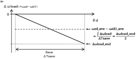
- the external load torque Tload is constant in the average processing angle section Save, and that the crank angular acceleration ⁇ load generated by the external load torque is constant. Therefore, as shown in FIG.
- the difference between the average value ⁇ sd_ave of the detection section angular velocity and the average value ⁇ id1_ave of the first ideal section angular velocity corresponds to the average value of the speed fluctuation amount ⁇ load in the averaging processing angle section Save.
- the average value of the speed fluctuation amount ⁇ load is a value obtained by dividing the speed fluctuation ⁇ load_end of the end angle of the averaging processing angle section Save by 2.
- the speed fluctuation ⁇ load_end of the end angle of the averaging processing angle section Save is a value obtained by multiplying the crank angular acceleration ⁇ load due to the external load torque by the averaging processing angle section Save.
- crank angular acceleration ⁇ load due to the external load torque is a value obtained by dividing the external load torque Tload by the moment of inertia Icrk.
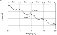
- Figure 10 shows a time chart of the test data. Note that the correction value Kc is set to 1, and the detection section angular velocity ⁇ sd fluctuates due to variation in the angle of the teeth of the signal plate 10.
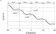
- FIG. 11 shows a time chart in which the second ideal interval angular velocity ⁇ id2 calculated using the accurately estimated external load torque Tload is overlaid on FIG. 10.
- the second ideal interval angular velocity ⁇ id2 overlaps with the detection interval angular velocity ⁇ sd, and it can be seen that the correction value Kc can be changed with high precision by comparing the second ideal interval angular velocity ⁇ id2 with the detection interval angular velocity ⁇ sd.
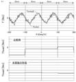
- the middle shows a time chart of a comparative example of the external load torque Tload calculated by multiplying the real shaft torque Tcrkd near the top dead center by the inertia torque Tin
- the bottom shows a time chart of the external load torque Tload according to this embodiment.
- the amount of fluctuation in the detection section angular velocity ⁇ sd near the top dead center differs for each average processing angle section Save
- the external load torque Tload fluctuates greatly for each average processing angle section Save.
- the effect of the fluctuation in the detection section angular velocity ⁇ sd during the average processing angle section Save is smoothed, so the amount of fluctuation in the external load torque Tload for each average processing angle section Save is small, and the external load torque Tload can be estimated with high accuracy.
- the external load torque estimation unit 61 estimates the external load torque Tload when the internal combustion engine is in an uncombusted state where no combustion is occurring (when the first condition is met). On the other hand, the external load torque estimation unit 61 does not estimate the external load torque Tload when the internal combustion engine is in a combusted state where combustion is occurring (when the first condition is not met).
- the uncombusted state includes a fuel cut state where the supply of fuel is stopped.
- the external load torque estimation unit 61 may calculate the final external load torque Tload by performing a smoothing process on the external load torque Tload estimated corresponding to the current and past average processing angle intervals Save.
- the rate of change of the external load torque Tload is slow, so by performing smoothing processing on multiple average processing angle intervals Save, the calculation accuracy of the external load torque Tload can be further improved.
- smoothing processes include moving average processing, weighted average processing, and low-pass filter processing such as first-order lag.
- Fig. 13 shows the behavior of the crank angular velocity ⁇ dcmp without correction processing calculated based on the angle interval ⁇ d and the time interval ⁇ Td that are not corrected by the correction value Kc, and the high-precision crank angular velocity ⁇ * detected by a high-precision rotation sensor provided for measurement, when the tooth arrangement crank angle varies.
- the crank angular velocity ⁇ dcmp without correction processing varies with respect to the high-precision crank angular velocity ⁇ * for measurement.
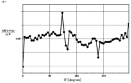
- FIG. 14 shows the angular velocity ratio at each crank angle, obtained by dividing the uncorrected crank angular velocity ⁇ dcmp by the high-precision crank angular velocity ⁇ * used for measurement.
- the angular velocity ratio is greater than 1, the actual angular interval is shorter than the specified angular interval (6 degrees), and when it is less than 1, the actual angular interval is longer than the specified angular interval (6 degrees). Therefore, unless the correction value Kc is appropriately changed and correction is performed using the correction value Kc to cancel out the fluctuations in the tooth arrangement crank angle, high-frequency components will be superimposed on the calculated crank angular velocity ⁇ d and crank angular acceleration ⁇ d, deteriorating the accuracy of internal combustion engine control, such as the estimation of the combustion state and combustion control.
- the process for appropriately changing the correction value Kc is described below.
- the second shaft torque estimation unit 62 adds the external load torque Tload to the estimated value Tcrke1(n) of the first shaft torque in each angle interval Sd(n) to calculate an estimated value Tcrke2(n) of the second shaft torque in each angle interval Sd(n).
- the second ideal angular velocity calculation unit 63 calculates a second ideal section angular velocity ⁇ id2, which is the angular velocity corresponding to each of the angle sections Sd(n) in a second ideal state assuming that there is no fluctuation in the multiple crank angles at which multiple teeth are arranged (hereinafter also referred to as tooth arrangement crank angles), based on the second shaft torque estimate value Tcrke2(n) for each of the angle sections Sd(n) and the moment of inertia Icrk of the crankshaft system.
- the second shaft torque estimate Tcrke2 is calculated by adding the external load torque Tload to the first shaft torque estimate Tcrk1 calculated using the physical model equation of the crank mechanism, and is therefore the shaft torque in the second ideal state assuming that there is no variation in the tooth arrangement crank angle.
- the second ideal interval angular velocity ⁇ id2 is calculated based on the second shaft torque estimate Tcrke2, and is therefore the interval angular velocity in the second ideal state.
- the second ideal angular velocity calculation unit 63 changes the correction value Kc(n) for each angle section Sd(n) so that the average value ⁇ sd_ave of the detection section angular velocity ⁇ sd in the average processing angle section Save does not deviate from the average detected angular velocity ⁇ saved, and matches the average value ⁇ id2_ave of the second ideal section angular velocity ⁇ id2 in the average processing angle section Save to the average detected angular velocity ⁇ saved.
- the second ideal angular velocity calculation unit 63 calculates the second ideal section angular acceleration ⁇ id2(n) which is the angular acceleration in the second ideal state corresponding to each of the angle sections Sd(n) based on the estimated value Tcrke2(n) of the second shaft torque in each of the angle sections Sd(n) and the moment of inertia Icrk of the crankshaft system, and integrates the second ideal section angular acceleration ⁇ id2(n) to calculate the provisional second ideal section angular velocity ⁇ id2tmp(n) which is the angular velocity in the second ideal state corresponding to each of the angle sections Sd(n).
- the second ideal angular velocity calculation unit 63 calculates the provisional second ideal section angular velocity ⁇ id2tmp using the following equation. This calculation process is performed for each angle section Sd(n) of the averaging processing angle section Save.
- the second ideal angular velocity calculation unit 63 calculates an average value ⁇ id2tmp_ave of the provisional second ideal section angular velocities ⁇ id2tmp in the averaging processing angle section Save, where Q is the angle identification number corresponding to the first angle section of the averaging processing angle section Save, and R is the angle identification number corresponding to the last angle section of the averaging processing angle section Save.
- the second ideal angular velocity calculation unit 63 subtracts the average value ⁇ id2tmp_ave of the provisional second ideal section angular velocity from the provisional second ideal section angular velocity ⁇ id2tmp and adds the average detected angular velocity ⁇ saved to calculate the second ideal section angular velocity ⁇ id2. This calculation process is performed for each angle section Sd(n) of the averaging processing angle section Save.
- This calculation process makes it possible to make the average value ⁇ id2_ave of the second ideal section angular velocity ⁇ id2 in the average processing angle section Save coincide with the average detected angular velocity ⁇ saved. Therefore, as described below, the correction value Kc is changed so that the detected section angular velocity ⁇ sd approaches the second ideal section angular velocity ⁇ id2, so that the correction value Kc can be changed so that the average value ⁇ sd_ave of the detected section angular velocity ⁇ sd in the average processing angle section Save does not deviate from the average detected angular velocity ⁇ saved.
- Figure 16 shows the control behavior when the provisional second ideal interval angular velocity ⁇ id2tmp is set as the second ideal interval angular velocity ⁇ id2 under the condition of a constant crank angular velocity.
- the average value ⁇ id2_ave of the second ideal interval angular velocity ⁇ id2 deviates from the average detected angular velocity ⁇ saved
- the average value ⁇ sd_ave of the detected interval angular velocity ⁇ sd deviates from the average detected angular velocity ⁇ saved
- Figure 17 shows the control behavior when corrected as in equation (21).
- the average value ⁇ id2_ave of the second ideal section angular velocity ⁇ id2 matches the average detected angular velocity ⁇ saved, so the average value ⁇ sd_ave of the detected section angular velocity ⁇ sd does not deviate from the average detected angular velocity ⁇ saved, the detected section angular velocity ⁇ sd does not shift, and no error occurs.
- the correction value changing unit 64 changes the correction value Kc(n) for each angle interval Sd(n) so that the detection interval angular velocity ⁇ sd(n), which is the angular velocity corresponding to the angle interval calculated from the time interval ⁇ Tdc and the angle interval ⁇ dc after correction processing using the correction value Kc, approaches the second ideal interval angular velocity ⁇ id2(n).
- the second ideal interval angular velocity ⁇ id2 is an interval angular velocity in the second ideal state, so high-frequency components due to fluctuations in the tooth arrangement crank angle are not superimposed.
- the second ideal interval angular velocity ⁇ id2 has good accuracy because it reflects the accurately estimated external load torque Tload. Therefore, by changing the correction value Kc(n) for each angle interval Sd(n) so that the detected interval angular velocity ⁇ sd(n) approaches the second ideal interval angular velocity ⁇ id2(n), the correction value Kc(n) can be appropriately changed to cancel out fluctuations in the tooth arrangement crank angle.
- the correction value change unit 64 increases the correction value Kc(n) when the detection section angular velocity ⁇ sd(n) exceeds the second ideal section angular velocity ⁇ id2(n) for each angle section Sd(n), and decreases the correction value Kc(n) when the detection section angular velocity ⁇ sd(n) falls below the second ideal section angular velocity ⁇ id2(n).
- the correction value changing unit 64 updates the correction value Kc(n) using the following equation: where Klrn is a learning rate, and a value of 1 or less is set.
- the correction value change unit 64 executes the process of changing the correction value Kc(n) for each angle section Sd(n) of the average processing angle section Save collectively each time the process of calculating the second ideal section angular velocity ⁇ id2(n) for each angle section Sd(n) of the average processing angle section Save is completed.
- the correction value change unit 64 changes the correction value Kc when the internal combustion engine is in an uncombusted state where no combustion is occurring (when the first condition is met). On the other hand, the correction value change unit 64 does not change the correction value Kc when the internal combustion engine is in a combusted state where combustion is occurring (when the first condition is not met).
- the uncombusted state includes a fuel cut state where the supply of fuel is stopped.
- the correction value change unit 64 also changes the correction value Kc when the absolute value of the amount of change in the average value of the detection section angular velocity ⁇ sd is equal to or less than the amount of change judgment value (when the second condition is satisfied). On the other hand, the correction value change unit 64 does not change the correction value Kc when the absolute value of the amount of change is greater than the amount of change judgment value (when the second condition is not satisfied).
- the average value of the detection section angular velocity ⁇ sd is set to, for example, the average value of an averaging period such as the average processing angle section Save or the stroke period.
- the correction value change unit 64 changes the correction value Kc when the operating amount of the brake mechanism of a vehicle equipped with an internal combustion engine is equal to or less than the operating amount judgment value (when the third condition is satisfied). On the other hand, the correction value change unit 64 does not change the correction value Kc when the operating amount of the brake mechanism is greater than the operating amount judgment value (when the third condition is not satisfied).
- the braking force of the brakes can cause the external load torque Tload to fluctuate significantly, which can lead to a deterioration in the accuracy of the change in the correction value Kc. Therefore, by changing the correction value Kc in a stable state where the amount of movement of the brake mechanism is small, the accuracy of the change in the correction value Kc can be improved.
- the correction value change unit 64 changes the correction value Kc when the clutch mechanism to which the crankshaft is connected is in a released state (when the fourth condition is satisfied). On the other hand, the correction value change unit 64 does not change the correction value Kc when the clutch mechanism is in a connected state (when the fourth condition is not satisfied).
- the clutch mechanism is provided between the crankshaft and the transmission.
- the accuracy of the change in the correction value Kc may deteriorate due to the external load torque Tload transmitted from the wheel side. Therefore, by changing the correction value Kc when the clutch mechanism is in a disengaged state, the accuracy of the change in the correction value Kc can be improved.
- the correction value change unit 64 changes the correction value Kc when the cooling water temperature of the internal combustion engine is equal to or higher than the first water temperature judgment value (when the fifth condition is satisfied). On the other hand, the correction value change unit 64 does not change the correction value Kc when the cooling water temperature is lower than the first water temperature judgment value (when the fifth condition is not satisfied). Alternatively, the correction value change unit 64 changes the correction value Kc when the cooling water temperature is equal to or higher than the first water temperature judgment value and is equal to or lower than a second water temperature judgment value higher than the first water temperature judgment value (when the fifth condition is satisfied).
- the correction value change unit 64 does not change the correction value Kc when the cooling water temperature is lower than the first water temperature judgment value or is higher than the second water temperature judgment value (when the fifth condition is not satisfied).
- the first water temperature judgment value and the second water temperature judgment value are preset to values such that the correction value Kc is changed when the internal combustion engine is warmed up and the cooling water temperature is at a normal operating temperature.
- the correction value change unit 64 changes the correction value Kc when all of the above first to fifth conditions are met, and does not change the correction value Kc when any one of the first to fifth conditions is not met.
- Figure 18 shows the behavior of the crank angular velocity ⁇ dcmp without correction calculated based on the angle interval ⁇ d and time interval ⁇ Td not corrected by the correction value Kc, the high-precision crank angular velocity ⁇ * detected by a high-precision rotation sensor provided for measurement, and the crank angular velocity ⁇ d after correction using the correction value Kc when a variation occurs in the tooth arrangement crank angle.
- the crank angular velocity ⁇ d after correction approaches the high-precision crank angular velocity ⁇ * used for measurement from the crank angular velocity ⁇ dcmp without correction. Therefore, the correction value Kc can be appropriately changed to cancel out the variation in the tooth arrangement crank angle, and the detection error of the crank angle ⁇ d can be accurately corrected.
- the abnormality determination unit 65 performs a smoothing process on the external load torque Tload estimated corresponding to the current and past average processing angle sections Save to calculate a smoothed value Tload_ave of the external load torque, calculates a torque difference ⁇ Tload between the external load torque Tload estimated corresponding to the current average processing angle section Save and the smoothed value Tload_ave of the external load torque, and determines the cylinder in which an abnormality has occurred based on the torque difference ⁇ Tload and the number i of the cylinder in the compression stroke corresponding to the current average processing angle section Save.
- the average section setting unit 54 sets the average processing angle section Save in correspondence with the compression stroke of each cylinder.
- the abnormality determination unit 65 determines that an abnormality has occurred in the cylinder in the compression stroke corresponding to the current average processing angle section Save.
- the judgment threshold may be different for the positive side and the negative side of the torque difference ⁇ Tload.
- the abnormality determination unit 65 may ultimately determine that an abnormality has been detected when the frequency at which an abnormality has been detected becomes greater than the judgment frequency. The abnormality determination unit 65 notifies the user of the occurrence of an abnormality by, for example, turning on a warning light.
- control device 50 according to a second embodiment will be described with reference to the drawings. Description of components similar to those of the first embodiment will be omitted.
- the basic configuration of the control device 50 according to the second embodiment is similar to that of the first embodiment, but the processing of the first ideal angular velocity calculation unit 57 and the second ideal angular velocity calculation unit 63 differs from that of the first embodiment.
- the first ideal angular velocity calculation unit 57 calculates the first ideal section angular velocity ⁇ id1, which is the angular velocity corresponding to each of the angle sections Sd in the first ideal state assuming that there is no fluctuation in the tooth arrangement crank angle and no external load torque Tload, based on the estimated value Tcrke1(n) of the first axial torque for each of the angle sections Sd(n) and the moment of inertia Icrk of the crankshaft system.
- the first ideal angular velocity calculation unit 57 calculates the first ideal section angular acceleration ⁇ id1(n), which is the angular acceleration in the first ideal state corresponding to each angle section Sd(n), based on the estimated value Tcrke1(n) of the first shaft torque for each angle section Sd(n) and the moment of inertia Icrk of the crankshaft system. This calculation process is performed for each angle section Sd(n) of the averaging processing angle section Save.
- the first ideal angular velocity calculation unit 57 changes the angle interval Sd one by one toward the advance angle side to set the angle interval Scal(n) to be calculated, calculates a first ideal time interval ⁇ Tid1(n) which is the time interval of the first ideal state corresponding to the angle interval Scal(n) to be calculated based on the first ideal interval angular acceleration ⁇ id1(n) corresponding to the angle interval Scal(n) to be calculated and the first ideal interval angular velocity ⁇ id1(n-1) calculated in the angle interval Scal(n-1) to be calculated one phase retard side, and calculates a first ideal interval angular velocity ⁇ id1(n) which is the angular velocity of the first ideal state corresponding to the angle interval Scal(n) to be calculated based on the first ideal time interval ⁇ Tid1(n) corresponding to the angle interval Scal(n).
- Q is the angle identification number corresponding to the first angle interval of the average processing angle interval Save
- R is the angle identification number corresponding to the end angle interval of the average processing angle interval Save.
- the first ideal angular velocity calculation unit 57 calculates a first ideal time interval ⁇ Tid1(n), which is the time interval of the first ideal state corresponding to the angle interval Scal(n) to be calculated, based on the first ideal interval angular acceleration ⁇ id1(n) corresponding to the angle interval Scal(n) to be calculated and the first ideal interval angular velocity ⁇ id1(n-1) calculated in the angle interval Scal(n-1) to be calculated on the one retard side.
- the first ideal angular velocity calculation unit 57 calculates the first ideal interval angular velocity ⁇ id1(n), which is the angular velocity of the first ideal state corresponding to the angle interval Scal(n) to be calculated, based on the first ideal time interval ⁇ Tid1(n) corresponding to the angle interval Scal(n) to be calculated.
- the angle identification number n is increased by one from Q to R, and the calculations of equations (24) and (25) are performed for each angle identification number n.
- the first ideal angular velocity calculation unit 57 sets the first ideal section angular velocity ⁇ id1 of the start angle of the average processing angle section Save to the detection section angular velocity ⁇ sd of the start angle of the average processing angle section Save.
- the second ideal angular velocity calculation unit 63 calculates the second ideal section angular velocity ⁇ id2, which is the angular velocity corresponding to each of the angle sections Sd in a second ideal state assuming that there is no fluctuation in the tooth arrangement crank angle, based on the second axial torque estimate value Tcrke2(n) for each of the angle sections Sd(n) and the moment of inertia Icrk of the crankshaft system.
- the second ideal angular velocity calculation unit 63 also changes the correction value Kc(n) for each angle section Sd(n) so that the average value ⁇ sd_ave of the detection section angular velocity ⁇ sd in the average processing angle section Save does not deviate from the average detected angular velocity ⁇ saved, and matches the average value ⁇ id2_ave of the second ideal section angular velocity ⁇ id2 in the average processing angle section Save to the average detected angular velocity ⁇ saved.
- the second ideal angular velocity calculation unit 63 calculates the second ideal section angular acceleration ⁇ id2(n), which is the angular acceleration in the second ideal state corresponding to each angle section Sd(n), based on the second shaft torque estimate value Tcrke2(n) for each angle section Sd(n) and the moment of inertia Icrk of the crankshaft system. This calculation process is performed for each angle section Sd(n) of the averaging processing angle section Save.
- the second ideal angular velocity calculation unit 63 changes the angle interval Sd one by one toward the advance angle side to set the angle interval Scal(n) to be calculated, calculates a second ideal time interval ⁇ Tid2(n) which is the time interval of the second ideal state corresponding to the angle interval Scal(n) to be calculated based on the second ideal interval angular acceleration ⁇ id2(n) corresponding to the angle interval Scal(n) to be calculated and the provisional second ideal interval angular velocity ⁇ id2tmp(n-1) calculated in the angle interval Scal(n-1) to be calculated one phase retard side, and calculates a provisional second ideal interval angular velocity ⁇ id2tmp(n) which is the angular velocity of the second ideal state corresponding to the angle interval Scal(n) to be calculated based on the second ideal time interval ⁇ Tid2(n) corresponding to the angle interval Scal(n).
- Q is the angle identification number corresponding to the first angle interval of the average processing angle interval Save
- R is the angle identification number corresponding to the end angle interval of the average processing angle interval Save.
- the second ideal angular velocity calculation unit 63 calculates a second ideal time interval ⁇ Tid2(n), which is the time interval of the second ideal state corresponding to the angle interval Scal(n) to be calculated, based on the second ideal interval angular acceleration ⁇ id2(n) corresponding to the angle interval Scal(n) to be calculated and the tentative second ideal interval angular velocity ⁇ id2tmp(n-1) calculated in the angle interval Scal(n-1) to be calculated on the one retard side.
- the second ideal angular velocity calculation unit 63 calculates a tentative second ideal interval angular velocity ⁇ id2tmp(n), which is the angular velocity of the second ideal state corresponding to the angle interval Scal(n) to be calculated, based on the second ideal time interval ⁇ Tid2(n) corresponding to the angle interval Scal(n) to be calculated.
- the angle identification number n is increased by one from Q to R, and the calculations of equations (27) and (28) are performed for each angle identification number n.
- the second ideal angular velocity calculation unit 63 calculates the average value ⁇ id2tmp_ave of the provisional second ideal section angular velocities ⁇ id2tmp in the averaging processing angle section Save.
- the second ideal angular velocity calculation unit 63 subtracts the average value ⁇ id2tmp_ave of the provisional second ideal section angular velocity from the provisional second ideal section angular velocity ⁇ id2tmp and adds the average detected angular velocity ⁇ saved to calculate the second ideal section angular velocity ⁇ id2. This calculation process is performed for each angle section Sd(n) of the averaging processing angle section Save.
- control device 50 according to a third embodiment will be described with reference to the drawings. Descriptions of components similar to those of the first or second embodiment will be omitted.
- the basic configuration of the control device 50 according to this embodiment is similar to that of the first or second embodiment, but the processing of the correction value changing unit 64 differs from that of the first or second embodiment.
- the correction value change unit 64 changes the correction value Kc(n) for each angle section Sd(n) so that the average value ⁇ sd_ave of the detection section angular velocity ⁇ sd in the average processing angle section Save does not deviate from the average detected angular velocity ⁇ saved, thereby matching the average value ⁇ sd_ave of the detection section angular velocity ⁇ sd in the average processing angle section Save to the average detected angular velocity ⁇ saved.
- the correction value changing unit 64 calculates the basic detection interval angular velocity ⁇ sdbs(n), which is the angular velocity corresponding to each angle interval Sd(n), based on the time interval ⁇ Tdc(n) and the angle interval ⁇ dc(n) after correction using the correction value. The following equation is used for this calculation. This calculation is performed for each angle interval Sd(n) of the averaging processing angle interval Save.
- the correction value change unit 64 calculates a basic detection section angular acceleration ⁇ sdbs(n), which is the angular acceleration corresponding to each angle section Sd(n), based on the basic detection section angular velocity ⁇ sdbs(n) corresponding to each angle section Sd(n) and the time interval ⁇ Tdc(n), and integrates the basic detection section angular acceleration ⁇ sdbs(n) to calculate a temporary detection section angular velocity ⁇ sdtmp(n), which is the angular velocity corresponding to each angle section Sd(n).
- the following equation is used for this calculation process. This calculation process is performed for each angle section Sd(n) of the averaging processing angle section Save.
- the correction value changing unit 64 calculates an average value ⁇ sdtmp_ave of the provisional detection section angular velocity ⁇ sdtmp in the averaging processing angle section Save.
- the correction value change unit 64 subtracts the average value ⁇ sdtmp_ave of the provisional detection section angular velocity ⁇ sdtmp(n) from the provisional detection section angular velocity ⁇ sdtmp(n) and adds the average detection angular velocity ⁇ saved to calculate the detection section angular velocity ⁇ sd(n). This calculation process is performed for the angle section Sd(n) of the averaging processing angle section Save.
- This calculation process makes it possible to make the average value ⁇ sd_ave of the detection section angular velocity in the averaging processing angle section Save coincide with the average detected angular velocity ⁇ saved. Therefore, the correction value Kc can be changed so that the average value ⁇ sd_ave of the detection section angular velocity ⁇ sd in the averaging processing angle section Save does not deviate from the average detected angular velocity ⁇ saved.
- the correction value change unit 64 changes the correction value Kc(n) for each angle interval Sd(n) so that the detection interval angular velocity ⁇ sd(n) approaches the second ideal interval angular velocity ⁇ id2(n) for each angle interval Sd(n).
- the second crank angle sensor 6 corresponds to the "specific crank angle sensor” in the present application
- the flywheel 27 corresponds to the "rotating member” in the present application
- the teeth of the ring gear 25 provided on the flywheel 27 correspond to the "detected portion” in the present application.
- the embodiments of the present application are not limited to this. That is, the first crank angle sensor 11 may correspond to the "specific crank angle sensor” in the present application, the signal plate 10 may correspond to the "rotating member” in the present application, and the multiple teeth provided on the signal plate 10 may correspond to the "detected portion” in the present application.
- the internal combustion engine 1 has been described as a gasoline engine. However, the embodiments of the present application are not limited to this. In other words, the internal combustion engine 1 may be any type of internal combustion engine, such as a diesel engine or an engine that performs Homogeneous-Charge Compression Ignition Combustion (HCCI combustion).
- HCCI combustion Homogeneous-Charge Compression Ignition Combustion
Landscapes
- Engineering & Computer Science (AREA)
- Chemical & Material Sciences (AREA)
- Combustion & Propulsion (AREA)
- Mechanical Engineering (AREA)
- General Engineering & Computer Science (AREA)
- Combined Controls Of Internal Combustion Engines (AREA)
Priority Applications (2)
| Application Number | Priority Date | Filing Date | Title |
|---|---|---|---|
| JP2025519218A JP7756839B2 (ja) | 2023-05-09 | 2023-05-09 | 内燃機関の制御装置 |
| PCT/JP2023/017384 WO2024232002A1 (ja) | 2023-05-09 | 2023-05-09 | 内燃機関の制御装置 |
Applications Claiming Priority (1)
| Application Number | Priority Date | Filing Date | Title |
|---|---|---|---|
| PCT/JP2023/017384 WO2024232002A1 (ja) | 2023-05-09 | 2023-05-09 | 内燃機関の制御装置 |
Publications (1)
| Publication Number | Publication Date |
|---|---|
| WO2024232002A1 true WO2024232002A1 (ja) | 2024-11-14 |
Family
ID=93431451
Family Applications (1)
| Application Number | Title | Priority Date | Filing Date |
|---|---|---|---|
| PCT/JP2023/017384 Ceased WO2024232002A1 (ja) | 2023-05-09 | 2023-05-09 | 内燃機関の制御装置 |
Country Status (2)
| Country | Link |
|---|---|
| JP (1) | JP7756839B2 (https=) |
| WO (1) | WO2024232002A1 (https=) |
Citations (7)
| Publication number | Priority date | Publication date | Assignee | Title |
|---|---|---|---|---|
| JP2006233941A (ja) * | 2005-02-28 | 2006-09-07 | Daihatsu Motor Co Ltd | 内燃機関の回転数制御方法 |
| JP2009275618A (ja) * | 2008-05-15 | 2009-11-26 | Mitsubishi Electric Corp | 角速度及び角加速度算出装置、トルク推定装置、燃焼状態推定装置 |
| JP2017072086A (ja) * | 2015-10-08 | 2017-04-13 | 三菱電機株式会社 | 内燃機関の制御装置 |
| JP2018199373A (ja) * | 2017-05-26 | 2018-12-20 | 日産自動車株式会社 | ハイブリッド車両のクランク角度推定方法、クランク角度制御方法およびクランク角度推定装置 |
| WO2022044092A1 (ja) * | 2020-08-24 | 2022-03-03 | 日産自動車株式会社 | ハイブリッド車両の制御方法、及び、ハイブリッド車両の制御装置 |
| JP7146131B1 (ja) * | 2022-04-15 | 2022-10-03 | 三菱電機株式会社 | 内燃機関の制御装置 |
| JP2022164167A (ja) * | 2021-04-16 | 2022-10-27 | 三菱電機株式会社 | 内燃機関の制御装置及び制御方法 |
-
2023
- 2023-05-09 JP JP2025519218A patent/JP7756839B2/ja active Active
- 2023-05-09 WO PCT/JP2023/017384 patent/WO2024232002A1/ja not_active Ceased
Patent Citations (7)
| Publication number | Priority date | Publication date | Assignee | Title |
|---|---|---|---|---|
| JP2006233941A (ja) * | 2005-02-28 | 2006-09-07 | Daihatsu Motor Co Ltd | 内燃機関の回転数制御方法 |
| JP2009275618A (ja) * | 2008-05-15 | 2009-11-26 | Mitsubishi Electric Corp | 角速度及び角加速度算出装置、トルク推定装置、燃焼状態推定装置 |
| JP2017072086A (ja) * | 2015-10-08 | 2017-04-13 | 三菱電機株式会社 | 内燃機関の制御装置 |
| JP2018199373A (ja) * | 2017-05-26 | 2018-12-20 | 日産自動車株式会社 | ハイブリッド車両のクランク角度推定方法、クランク角度制御方法およびクランク角度推定装置 |
| WO2022044092A1 (ja) * | 2020-08-24 | 2022-03-03 | 日産自動車株式会社 | ハイブリッド車両の制御方法、及び、ハイブリッド車両の制御装置 |
| JP2022164167A (ja) * | 2021-04-16 | 2022-10-27 | 三菱電機株式会社 | 内燃機関の制御装置及び制御方法 |
| JP7146131B1 (ja) * | 2022-04-15 | 2022-10-03 | 三菱電機株式会社 | 内燃機関の制御装置 |
Also Published As
| Publication number | Publication date |
|---|---|
| JP7756839B2 (ja) | 2025-10-20 |
| JPWO2024232002A1 (https=) | 2024-11-14 |
Similar Documents
| Publication | Publication Date | Title |
|---|---|---|
| CN107269409B (zh) | 内燃机的控制装置及其控制方法 | |
| CN106988919B (zh) | 内燃机的控制装置及其控制方法 | |
| US10724461B2 (en) | Controller and control method for internal combustion engine | |
| JP7146131B1 (ja) | 内燃機関の制御装置 | |
| US11473517B1 (en) | Controller and control method for internal combustion engine | |
| US11480121B2 (en) | Controller and control method for internal combustion engine | |
| US11555462B2 (en) | Controller and control method for internal combustion engine | |
| JP7030884B2 (ja) | 内燃機関の制御装置 | |
| JP7756839B2 (ja) | 内燃機関の制御装置 | |
| JP7191187B1 (ja) | 内燃機関の制御装置 | |
| US11703418B2 (en) | Controller for internal combustion engine | |
| WO2025182061A1 (ja) | 内燃機関の制御装置 | |
| WO2025182062A1 (ja) | 内燃機関の制御装置 | |
| JP7621562B2 (ja) | 内燃機関のトルク推定装置 | |
| JP7814617B2 (ja) | 内燃機関の制御装置 | |
| JP7191188B1 (ja) | 内燃機関の制御装置 | |
| WO2025197019A1 (ja) | 内燃機関の制御装置 |
Legal Events
| Date | Code | Title | Description |
|---|---|---|---|
| 121 | Ep: the epo has been informed by wipo that ep was designated in this application |
Ref document number: 23936556 Country of ref document: EP Kind code of ref document: A1 |
|
| WWE | Wipo information: entry into national phase |
Ref document number: 2025519218 Country of ref document: JP |
|
| NENP | Non-entry into the national phase |
Ref country code: DE |