WO2024225439A1 - 蓄放電システム、及び蓄電素子 - Google Patents
蓄放電システム、及び蓄電素子 Download PDFInfo
- Publication number
- WO2024225439A1 WO2024225439A1 PCT/JP2024/016460 JP2024016460W WO2024225439A1 WO 2024225439 A1 WO2024225439 A1 WO 2024225439A1 JP 2024016460 W JP2024016460 W JP 2024016460W WO 2024225439 A1 WO2024225439 A1 WO 2024225439A1
- Authority
- WO
- WIPO (PCT)
- Prior art keywords
- terminal
- storage
- power
- storage battery
- electrode
- Prior art date
- Legal status (The legal status is an assumption and is not a legal conclusion. Google has not performed a legal analysis and makes no representation as to the accuracy of the status listed.)
- Ceased
Links
Images






Classifications
-
- Y—GENERAL TAGGING OF NEW TECHNOLOGICAL DEVELOPMENTS; GENERAL TAGGING OF CROSS-SECTIONAL TECHNOLOGIES SPANNING OVER SEVERAL SECTIONS OF THE IPC; TECHNICAL SUBJECTS COVERED BY FORMER USPC CROSS-REFERENCE ART COLLECTIONS [XRACs] AND DIGESTS
- Y02—TECHNOLOGIES OR APPLICATIONS FOR MITIGATION OR ADAPTATION AGAINST CLIMATE CHANGE
- Y02E—REDUCTION OF GREENHOUSE GAS [GHG] EMISSIONS, RELATED TO ENERGY GENERATION, TRANSMISSION OR DISTRIBUTION
- Y02E60/00—Enabling technologies; Technologies with a potential or indirect contribution to GHG emissions mitigation
- Y02E60/10—Energy storage using batteries
Definitions
- the present invention relates to a storage and discharge system and a storage element.
- Patent Documents 1 and 2 Power generation and storage units and storage elements that use solar panels are known (see, for example, Patent Documents 1 and 2).
- the above-mentioned power generation/storage units and storage elements may not be able to efficiently generate and output stable electricity from unstable electricity generated from natural energy sources, etc.
- the present invention was conceived in consideration of these problems, and aims to provide a storage/discharge system that generates and outputs stable power with high efficiency from unstable power generated from natural energy sources, etc., and a storage element that can be used therewith.
- this is not the only objective of the present invention.
- Another objective of the present invention is to achieve effects that cannot be obtained by conventional technology, which are derived from the configurations shown in the embodiments of the invention described below.
- a storage/discharge system for solving the above problems includes a power generating unit having a first internal resistance and supplying DC power from an output terminal, and a storage battery connected in parallel to the output terminal of the power generating unit and having a second internal resistance lower than the first internal resistance.
- the energy storage element for solving the above problems is an energy storage element constituting a storage battery capable of being charged with DC power supplied from a power generating unit, comprising: a first electrode having a first polarity current collector and an active material layer formed on the surface of the first polarity current collector; a second electrode having a second polarity current collector and an active material layer formed on the surface of the second polarity current collector; a separator sandwiched between the first electrode and the second electrode; a first terminal for charging connected to the first polarity current collector; a second terminal for charging connected to the second polarity current collector; a third terminal for discharging connected to the first polarity current collector and separated from the first terminal; and a fourth terminal connected to the second polarity current collector and the same as or separated from the second terminal.
- the maximum current supplied by the power generation unit is defined as I INMAX
- the rated input current of the storage battery is defined as I BR
- the longer of the distance between the first terminal and the second terminal and the distance between the third terminal and the fourth terminal is defined as L P-N
- the distance between the first terminal and the third terminal is defined as L P-P
- the disclosed storage/discharge system and storage element make it possible to realize a storage/discharge system that can generate stable power with high efficiency.
- FIG. 1 is a block diagram illustrating a storage/discharge system according to a first embodiment.
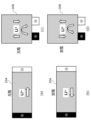
- 5A to 5D are diagrams illustrating the charge and discharge operation of the two-terminal element according to the embodiment.
- 5A and 5B are diagrams illustrating the movement of electrons and lithium ions in a two-terminal element having a double-sided tab structure in accordance with the embodiment.
- 5A and 5B are diagrams illustrating the movement of electrons and lithium ions in a two-terminal element with a one-side tab structure in the embodiment.
- 2 is a diagram illustrating a configuration of a storage battery using a two-terminal element according to the embodiment;
- FIG. 2 is a block diagram illustrating a storage/discharge system according to a first comparative example to the embodiment.
- FIG. 11 is a block diagram illustrating a storage/discharge system according to a second comparative example to the embodiment.
- 5A and 5B are diagrams illustrating the influence of the output voltage of a solar power generator in the storage and discharge system according to the first and second embodiments.
- FIG. 11 is a diagram illustrating a first configuration of a three-terminal element according to a second embodiment.
- FIG. 5A and 5B are diagrams illustrating a second configuration of the three-terminal element according to the embodiment.
- 13A and 13B are diagrams showing the configuration of a three-terminal element according to a comparative example of the embodiment.
- 11A to 11C are diagrams illustrating the movements of electrons and lithium ions in a second configuration of the three-terminal element according to the embodiment.
- FIG. 2 is a diagram illustrating a configuration of a storage battery using a three-terminal element according to the embodiment
- FIG. 11A and 11B are diagrams illustrating another configuration of a storage battery using a three-terminal element according to the same embodiment.
- FIG. 11 is a block diagram illustrating a storage-discharge system including a wind power generator according to a third embodiment.
- 2 is a block diagram illustrating a storage-discharge system including a plurality of wind power generators according to the embodiment.
- FIG. 2 is a block diagram illustrating a storage-discharge system including a solar power generator, a wind power generator, and a hydroelectric power generator according to the embodiment.
- FIG. 1 is a block diagram illustrating a storage/discharge system 100 according to an embodiment.
- the storage and discharge system 100 comprises one or more storage batteries 1, one or more solar panels 2A (photovoltaic generators), a D-CS (Direct-Charge System) 3, and a DC/AC inverter 4.
- the storage battery 1 may be, for example, a lithium ion secondary battery (hereinafter simply referred to as a "lithium ion battery”), preferably a manganese-based lithium ion battery.
- a lithium ion secondary battery hereinafter simply referred to as a "lithium ion battery”
- a manganese-based lithium ion battery preferably a manganese-based lithium ion battery.
- the storage battery 1 is connected in parallel to the solar panel 2A via the D-CS3.
- the D-CS3 has the function of cutting off the input circuit or output circuit depending on the battery voltage to prevent overcharging or over-discharging of the storage battery 1, but in the normal state when charging and discharging are performed, the solar panel 2A and the storage battery 1 are directly connected, and are also directly connected to the DC/AC inverter 4.
- the D-CS3 may simply be a switch.
- the panel voltage (e.g., 300V to 400V) is fixed to the battery voltage.
- MPPT Maximum Power Point Tracking
- the panel voltage is constant in the storage/discharge system 100 shown in Figure 1.
- the panel voltage increases due to the cable resistance and current up to the storage battery 1, but is basically the battery voltage.
- the input voltage to the DC/AC inverter 4 is fixed to the battery voltage, and fluctuations in the required power are handled by changing the amount of current. If the required current of the DC/AC inverter 4 is smaller than the generated current, it is covered by the current from the solar panel 2A, and the surplus current is automatically diverted to charge the storage battery 1. Also, if the required current of the DC/AC inverter 4 is greater than the amount of power generated by the solar panel 2A, the shortfall in current is automatically discharged from the storage battery 1.
- the solar panel 2A may have a first internal resistance and function as an example of a power generating unit that supplies DC power from an output terminal.
- the storage battery 1 may be connected in parallel with the output terminal of the power generating unit and have a second internal resistance lower than the first internal resistance.
- the DC power discharged by the storage battery 1 may be converted to at least one of a desired AC power or DC power and output.
- the first internal resistance varies depending on the environmental temperature of the power generating unit, and the second internal resistance may be lower than the minimum value of the first internal resistance.
- the storage battery 1 is composed of one or more storage elements (cells). Each storage element is usually composed of a sheet-like body formed by laminating a positive electrode, a negative electrode, and a separator that insulates them. There are two types of storage element structures: a jelly roll type in which the sheet-like body is wound into a roll, and a stack type in which multiple sheet-like bodies are stacked.
- stack-type storage elements mainly include a double-side tab structure in which a positive electrode tab (positive electrode terminal) and a negative electrode tab (negative electrode terminal) are provided on opposing sides of the sheet-like body, and a single-side tab structure in which a positive electrode tab and a negative electrode tab are provided on the same side of the sheet-like body.
- storage elements include a two-terminal element in which one positive electrode tab and one negative electrode tab are shared for charging and discharging, and an element that has a separate positive electrode tab for charging and a positive electrode tab for discharging.
- an element that has two positive electrode tabs for charging and discharging and one negative electrode tab shared for charging and discharging is called a three-terminal element.
- a case where a two-terminal element is used will be described.
- FIG. 2 is a diagram explaining the charging and discharging operation of a two-terminal element.
- FIG. 2(a) shows the charging operation of a two-terminal element 20A with a double-sided tab structure
- FIG. 2(b) shows the discharging operation thereof
- FIG. 2(c) shows the charging operation of a two-terminal element 20B with a single-sided tab structure
- FIG. 2(d) shows the discharging operation thereof.
- lithium ions (Li + in the figure) move in the active material layer from the positive electrode to the negative electrode
- lithium ions move in the active material layer from the negative electrode to the positive electrode
- lithium ions move through the active material layer from the positive electrode to the negative electrode, and also move back and forth within the active material layer.
- lithium ions move through the active material layer from the negative electrode to the positive electrode, and also move back and forth within the active material layer.
- the active material layer structure is the same in both the double-sided tab structure and the single-sided tab structure, differences occur in the movement of lithium ions depending on the position of the electrodes.
- the movement of lithium ions is relatively uniform, but because there is a distance between the positive and negative electrodes, the lithium ions travel a long distance.
- the lithium ions travel a short distance at the start of charging and discharging, making it possible to discharge large currents with low resistance.
- the diffusion of available lithium ions gradually becomes farther, so the resistance gradually increases.
- repeated charging and discharging can cause the distribution of lithium ions to become uneven.
- FIGS. 3A and 3B are diagrams illustrating the movement of electrons (e ⁇ in the figure) and lithium ions (Li + in the figure) in a two-terminal element 20A with a double-sided tab structure.
- Fig. 3A shows the case of charging
- Fig. 3B shows the case of discharging.
- the two-terminal element 20A includes a positive electrode composed of a positive electrode collector 21 and a positive electrode side active material layer 22 formed on the surface of the positive electrode collector 21, a negative electrode composed of a negative electrode collector 25 and a negative electrode side active material layer 24 formed on the surface of the negative electrode collector 25, and a separator 23 that separates the positive electrode side active material layer 22 and the negative electrode side active material layer 24.
- FIGS. 4A and 4B are diagrams illustrating the movement of electrons (e ⁇ in the figure) and lithium ions (Li + in the figure) in a two-terminal element 20B with a one-side tab structure.
- Fig. 4A shows the case of charging
- Fig. 4B shows the case of discharging.
- the positive electrode tab and the negative electrode tab are close to each other, so that lithium ions move quickly when charging and discharging begins, enabling high input and output.
- the lithium ion diffusion area 26 is not between the positive electrode tab and the negative electrode tab, but is located far from both tabs, it does not contribute to the diffusion of lithium ions that affects charging and discharging. As a result, the movement of lithium ions gradually slows down, and the charge and discharge rate decreases over time. In addition, because the movement of lithium ions increases in places close to both tabs, it is prone to becoming uneven.
- FIG. 5 is a diagram illustrating the configuration of a storage battery 1 using a two-terminal element 20.
- the two-terminal element 20 in the diagram may be either a two-terminal element 20A with a double-side tab structure or a two-terminal element 20B with a single-side tab structure.
- the two-terminal elements 20 are connected in series as shown in Figure 5, in both the one-side tab structure and the two-side tab structure. This makes it possible to configure a storage battery 1 whose battery voltage is the sum of the cell voltages of the two-terminal elements 20.
- the charging input and the load output are directly connected, so the input voltage affects the output voltage, and conversely, the output voltage affects the input voltage.
- the panel voltage In direct charging, the panel voltage is fixed at the battery voltage (normally the discharge voltage), so it is necessary to choose whether to charge or discharge. To build a system that passes through only the amount used as a load and charges only the surplus, the charge voltage and discharge voltage of storage battery 1 must be equal.
- Lithium ion batteries which use the intercalation phenomenon rather than an electrochemical reaction that has a polarization potential during charging and discharging, achieve these characteristics and are well suited for use in the storage and discharging system 100 shown in Figure 1.
- FIG. 6 is a block diagram illustrating a storage/discharge system 600 according to a first comparative example to this embodiment.
- the storage/discharge system 600 includes a storage battery 6, one or more solar panels 2A (photovoltaic generators), a charge/discharge controller 7, and a power controller that combines a DC/AC inverter 8a and an MPPT circuit 8b.
- a storage battery 6 one or more solar panels 2A (photovoltaic generators), a charge/discharge controller 7, and a power controller that combines a DC/AC inverter 8a and an MPPT circuit 8b.
- the current and voltage of the solar panel 2A change depending on the state, but the role of the MPPT circuit 8b is to maximize this power P.
- the MPPT circuit 8b continuously changes the voltage of the solar panel 2A and searches for the point where the change in current x voltage is at a maximum.
- the charge/discharge controller 7 is connected to the DC/AC inverter 8a and controls the charging and discharging of the storage battery 6.
- the output of the solar panel 2A is converted to 100V AC voltage by the power controller.
- This 100V AC voltage is then AC/DC converted to a DC voltage and charged to the storage battery 6.
- the DC voltage discharged from the storage battery 6 is also converted back to 100V AC voltage and returned to the power controller.
- FIG. 7 is a block diagram illustrating a storage/discharge system 700 according to a second comparative example to this embodiment.
- the storage/discharge system 700 includes a storage battery 6, one or more solar panels 2A, a charge/discharge controller 7, and a power controller that combines a DC/AC inverter 8a and an MPPT circuit 8b.
- the storage/discharge system 700 is an efficiency-improved system known as a multi-DC link type, in which the DC voltage output from the MPPT circuit 8b is directly charged to the storage battery 6, and the DC voltage discharged from the storage battery 6 is returned to the MPPT bus and output via the DC/AC inverter 8a.
- storage and discharge system 700 tends to have a higher power generation amount relative to the amount of solar radiation, i.e., a higher power generation efficiency. Also, in storage and discharge system 600, a phenomenon called recombination often occurs, in which the amount of power generation and power generation efficiency vary when the amount of solar radiation or temperature increases, but this recombination is less likely to occur in storage and discharge system 700.
- the current amount from the MPPT circuit 8b is detected, the missing power is requested from the storage battery 6, and after DC/AC ⁇ AC/DC ⁇ DC/DC conversion, it is necessary to mix and further perform DC/AC conversion.
- the missing power from the MPPT circuit 8b is requested from the storage battery 6, and the missing power is supplied to the DC/AC inverter 8a through a DC/DC converter (not shown).
- monitoring of the current amount and management of charging and discharging the storage battery 1 are required, but according to the storage/discharge system 100 shown in FIG. 1, the panel voltage is fixed at the battery voltage, so charging and discharging of the storage battery 1 is automatically switched at the requested current amount, enabling efficient operation without DC/DC conversion.
- the resistance of the elements decreases as the temperature rises.
- the internal resistance of electronic circuits such as the MPPT circuit 8b does not change because they are placed in the shade.
- the resistance of the conductors included in the MPPT circuit 8b increases with increasing temperature, so while the resistance of the solar panel 2A decreases as the temperature of the solar panel 2A rises, the circuit resistance of the MPPT circuit 8b remains the same or increases.
- lithium-ion batteries have a lower internal resistance than many chemical batteries.
- Manganese-based lithium-ion batteries in particular have a low internal resistance, and can maintain a lower resistance even when solar panel 2A heats up and its resistance drops, making it possible to maintain the power generation efficiency of solar panel 2A even when it is exposed to strong light at a high temperature.
- the storage battery can be configured with a three-terminal element or a four-terminal element in addition to the two-terminal element 20 described in the first embodiment. Therefore, in the second embodiment, a storage and discharge system using a three-terminal element will be described. Note that a four-terminal element is also applicable in this embodiment.
- the energy storage element described in Patent Document 2 comprises a positive electrode, a negative electrode, a separator, and first to third terminals.
- the first terminal is a charging terminal (tab) connected to the outer periphery of the positive electrode current collector
- the second terminal is connected to the outer periphery of the negative electrode current collector and is a terminal used for at least one of charging and discharging
- the third terminal is a discharging terminal connected to the outer periphery of one of the positive electrode current collector and the negative electrode current collector at a distance from the first terminal or the second terminal.
- the amount of current changes depending on the size of the load, so as the load (current) increases, the panel voltage rises and the current decreases accordingly.
- the storage battery is disconnected from the load, and the storage battery is also disconnected from the solar panel. Therefore, even if the load (current) increases, the relationship between the storage battery voltage and the panel voltage does not change, preventing a decrease in current.
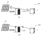
- FIG. 8 is a diagram explaining the influence of the output voltage of the solar panel 2A in the storage/discharge system.
- FIG. 8(a) shows the case of a storage/discharge system 100 using the two-terminal element 20 according to the first embodiment
- FIG. 8(b) shows the case of a storage/discharge system 200 using the three-terminal element 30 according to this embodiment.
- the input terminal of the three-terminal element 30 is connected in parallel to the solar panel 2A, and the output terminal is connected to the DC/AC inverter 4.
- the solar panel 2A and the storage battery 1 circuit are separated, and the storage battery 1 and the DC/AC inverter 4 circuit are separated.
- the two-terminal element 20 absorbs current fluctuations, current, and voltage noise that may occur when the storage battery 1 is connected in parallel. Also, when the current required from the DC/AC inverter 4 exceeds the current from the solar panel 2A, the terminal voltage of the storage battery 1 drops, but because the input circuit (connection to the solar panel 2A) and the output circuit (connection to the DC/AC inverter 4) are separated by the three-terminal element 30, the battery voltage becomes the standard, the panel voltage is the battery voltage + cable resistance x current, and the voltage to the DC/AC inverter 4 is the battery voltage - cable resistance x current. As a result, the voltage of the entire storage/discharge system 200 becomes high, and the power generation efficiency itself becomes high.
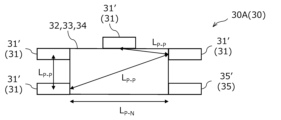
- FIG. 9 is a diagram illustrating a first configuration ( 30 A) of the three-terminal element 30 .
- the three-terminal element 30 is composed of a positive electrode (first electrode) having a positive electrode collector 31 (first polarity collector) and an active material layer 32 formed on the surface of the positive electrode collector 31 (first polarity collector), a negative electrode (second electrode) having a negative electrode collector 35 (second polarity collector) and an active material layer 34 formed on the surface of the negative electrode collector 35 (second polarity collector), and a separator 33 sandwiched between the positive electrode and the negative electrode.
- the three-terminal element 30 also includes a positive electrode tab 31' (first terminal) for charging connected to the positive electrode collector 31 (first polarity collector), a negative electrode tab 35' (second terminal) for both charging and discharging connected to the negative electrode collector 35 (second polarity collector), and a positive electrode tab 31' (third terminal) for discharging connected to the positive electrode collector 31 (first polarity collector) and separated from the positive electrode tab 31' (first terminal) for charging.
- a negative electrode tab (second terminal) for charging connected to the negative electrode collector (second polarity collector) and a negative electrode tab (fourth terminal) for discharging separate from this negative electrode tab (second terminal) may be provided to form a four-terminal element.
- four positive electrode tabs 31' are shown in Figure 9, these are examples of the arrangement of the positive electrode tabs 31', and in reality, two positive electrode tabs 31' should be provided.
- the distance between the positive electrode tab 31′ (first terminal) and the negative electrode tab 35′ (second terminal) for charging and the distance between the positive electrode tab 31′ (third terminal) and the negative electrode tab 35′ for discharging is defined as L P-N
- the distance between the positive electrode tabs 31′ is defined as L P-P
- the maximum current supplied by the solar panel 2A (power generating unit) is defined as I INMAX
- the rated input current of the storage battery 1 is defined as I BR , then the following formula 1 may be obtained.
- Formula 1 can also be applied to a four-terminal element having two negative electrode tabs, one for charging and one for discharging.
- the longer of the distance between the positive electrode tab for charging (first terminal) and the negative electrode tab for charging (second terminal) and the distance between the positive electrode tab for discharging (third terminal) and the negative electrode tab for discharging (fourth terminal) can be defined as L P-N .
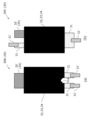
- FIG. 10 is a diagram illustrating a second configuration (30B, 30C) of the three-terminal element 30, and FIG. 11 is a diagram illustrating the configurations of three-terminal elements 30D and 30E, which are comparative examples of the three-terminal elements 30B and 30C.
- two positive electrode tabs 31' are provided at the end of the positive electrode collector 31, and one negative electrode tab 35' is provided at the end of the negative electrode collector 35.
- a bypass circuit is formed between the two positive electrode tabs 31' that does not pass through the active material layers 32 and 34, but passes through the uncoated portion of the active material.
- the three-terminal elements 30B and 30C also have two positive electrode tabs 31' on the positive electrode current collector 31, as in the comparative example.
- the positive electrode first electrode
- at least active material layers 32 and 34 are formed on the path between the two positive electrode tabs 31' (first terminal and third terminal).
- the three-terminal element 30B like the comparative three-terminal elements 30D and 30E, has two positive electrode tabs 31' provided on the positive electrode collector 31 and a negative electrode tab 35' provided on the negative electrode collector 35, and the two positive electrode tabs 31' are both positioned with the active material layers 32, 34 sandwiched between them and the negative electrode tab 35'.
- the three-terminal element 30B has a notch 31a that reaches the active material layers 32, 34 in the portion of the positive electrode collector 31 located between the two positive electrode tabs 31', so that the active material layers 32, 34 are always present between the two positive electrode tabs 31'.
- the two positive electrode tabs 31' provided on the positive electrode collector 31 are arranged with the active material layers 32 and 34 sandwiched between them. Even in this case, as in the case shown in FIG. 10(a), the active material layers 32 and 34 are always interposed between the two positive electrode tabs 31'.
- FIG. 12 is a diagram for explaining the movement of electrons (e ⁇ in the figure) and lithium ions (Li + in the figure) in the three-terminal element 30B having the second configuration. The same applies to the three-terminal element 30C.
- the three-terminal element 30B is divided into a charging section 37 located on the side of the negative electrode collector 35 where electrons flow in and the side of the positive electrode collector 31 where electrons flow out, a discharging section 38 located on the side of the positive electrode collector 31 where electrons flow in and the side of the negative electrode collector 35 where electrons flow out, and a diffusion section 36 located between the charging section 37 and the discharging section 38.
- the charging section 37 is the area where lithium ions move from the active material layer 32 on the positive electrode side to the active material layer 34 on the negative electrode side during charging.
- the discharging section 38 is the area where lithium ions move from the active material layer 34 on the negative electrode side to the active material layer 32 on the positive electrode side during discharging. This is the same for a four-terminal element.
- the active material layers of the positive electrode (first electrode) and negative electrode (second electrode) have a charging section 37 that serves as a path between the positive electrode tab (first terminal) and negative electrode tab (second terminal) for charging, a discharging section 38 that serves as a path between the positive electrode tab (third terminal) and negative electrode tab (fourth terminal) for discharging, and a diffusion section 36 through which lithium ions diffuse and which separates the charging section 37 and the discharging section 38.
- the input terminal and output terminal are connected to the same positive electrode tab.
- the part where the active material is applied, that is, the diffusion part 26, has a constant voltage depending on the distribution amount of lithium ions, whereas the uncoated part is located closer to the input terminal and output terminal, so when the output current is greater than the input current, the terminal voltage drops below the voltage of the diffusion part 26. This is because the uncoated part acts as a bypass, causing a voltage drop.
- the positive electrode tabs 31' are separate for charging and discharging, but there is an uncoated portion of active material between the two positive electrode tabs 31'. And because this uncoated portion becomes a bypass between the two positive electrode tabs 31', it is affected by the voltage drop from the load.
- FIG. 13 is a diagram showing an example of the configuration of a storage battery 1 using a three-terminal element 30.
- the three-terminal element 30 in the diagram is any one of three-terminal elements 30A to 30C.
- the storage battery 1 shown in Figure 13 is composed of a three-terminal element 30 and multiple two-terminal elements 20 connected in series to the charging section 37, the diffusion section 36, and the discharging section 38 of the three-terminal element 30. Of these, the three-terminal element 30 is used for input and output. The two-terminal elements 20 connected in series are used for voltage adjustment to increase the voltage. Note that the same position in the horizontal direction in Figure 13 indicates equal voltages.
- the charging section 37, the diffusion section 36, and the discharging section 38 are depicted as being of the same size, but in reality, the charging section 37 and the discharging section 38 are very narrow regions near the positive or negative electrode tab.
- the charging section 37 and the discharging section 38 are very narrow regions near the positive or negative electrode tab.
- lithium ions Li + in Fig. 12
- the charging section 37 and the discharging section 38 have the same voltage as the overwhelmingly large diffusion section 36.
- the charging section 37, the diffusion section 36, and the discharging section 38 are connected by a conductor (current collector), so they are affected by the voltage of the discharging section 38, but in reality, they are fixed by the voltage of the diffusion section 36.
- the solar panel 2A which is the power generating unit, accepts it as a current regardless of the voltage, transmits it to the diffusion unit 36 in the form of the movement of electrons (e - in FIG. 12), and can be taken out as a current of a constant voltage from the output unit.
- the input terminal and the output terminal are electrically connected by the two-terminal element 20, part of the noise that enters the solar panel 2A is absorbed by the diffusion unit 26, but the amount proportionally distributed by the internal resistance is output from the discharge unit 28 as noise.
- FIG. 14 is a diagram showing another example of the configuration of a storage battery 1 using a three-terminal element 30.
- the three-terminal element 30 in the diagram is any one of three-terminal elements 30A to 30C.
- the storage battery 1 is configured such that the charging section 37, the diffusion section 36, and the discharge section 38 are electrically connected within the three-terminal element 30, of which the diffusion section 36 is connected in series with a number of two-terminal elements 20.
- the negative electrodes of the charging section 37, the diffusion section 36, and the discharge section 38 are common, so that a two-terminal element 20 can be connected in series thereto as necessary to realize a high-voltage device.
- two-terminal elements 20 that match the voltage, including the three-terminal element 30, can be connected in series, and a positive electrode tab for discharging can be connected to the positive electrode with the highest voltage, absorbing input noise and configuring a system capable of discharging a large current by increasing the number of storage batteries 1 in parallel.
- the two-terminal element 20 is connected to the diffusion portion 36 of the three-terminal element 30, but this embodiment is not limited to this, and the two-terminal element 20 may be connected to the charging portion 37 or the discharging portion 38.
- FIG. 15 is a block diagram illustrating a storage/discharge system 300 equipped with a wind power generator (wind turbine 2B).
- the storage and discharge system 300 is an example in which a wind power generator is used instead of the solar power generator of the storage and discharge system 100.
- Wind power generation by the wind turbine 2B (power generation source) is an AC power generation source in which the voltage and current change depending on the rotation speed.
- the storage and discharge system 300 is equipped with a diode bridge 5 (AC-DC conversion section) that converts AC power to DC power on the output side of the wind turbine 2B.
- the storage battery 1 can be charged by connecting the output of this diode bridge 5 in parallel.
- the battery voltage fixes the output voltage of the diode bridge 5, similar to the power generation by the solar panel 2A, so the voltage of the wind power generator (windmill 2B) is fixed.
- the rotation speed is fixed, and the energy from the wind current is converted into current, similar to the power generation by the solar panel 2A.
- the input circuit and output circuit are separated, so spikes (current and voltage fluctuations) caused by wind fluctuations (gusts of wind, etc.) are absorbed and do not affect the DC/AC inverter side, eliminating the need for the noise filter that was previously required, is expensive, and causes efficiency to decrease.
- the generated energy can be stored or discharged without loss, achieving maximum efficiency.
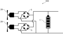
- FIG. 16 is a block diagram illustrating a storage/discharge system 400 equipped with multiple wind power generators (wind turbines 2B).
- the storage and discharge system 400 includes a power generation unit configured by connecting in parallel a combination of wind turbines 2B and a diode bridge 5 connected to the output of the wind turbines 2B.
- the storage and discharge system 400 also includes a storage battery 1 connected in parallel to each diode bridge 5. In this configuration, each wind turbine 2B can be controlled by the voltage of the common storage battery 1, so electricity can be generated and stored without using a control circuit.
- the cost of the wind turbine control circuits such as the over-speed control circuit and pulse power generation control, or the noise filter circuit that absorbs the generated noise, is higher than the cost of the wind turbine 2B itself.
- the storage and discharge system 400 allows multiple wind turbines 2B to be managed and stored with just the storage circuit, making it possible to significantly reduce costs.
- FIG. 17 is a block diagram illustrating a storage/discharge system 500 equipped with a solar power generator (solar panel 2A), a wind power generator (wind turbine 2B), and a hydroelectric power generator (water turbine 2C).
- a solar power generator solar panel 2A
- a wind power generator wind turbine 2B
- a hydroelectric power generator water turbine 2C
- the storage and discharge system 500 is a combined power generation system that combines solar power generation, wind power generation, and hydroelectric power generation.
- the voltage of the storage battery 1 controls the solar power generation, wind power generation, and hydroelectric power generation, respectively, so the difference between DC and AC power generation is not an issue, and the storage battery 1 performs the power generation control itself. Therefore, by optimizing the voltage setting, combined power generation is easily possible.
- the power charged in the storage battery 1 corresponding to each of the solar panel 2A, wind turbine 2B, and water turbine 2C may be discharged and charged into a common main battery 9.
- the storage battery 1 can also discharge large currents, in locations where solar, wind or hydroelectric power generation is possible, it is possible to create an EV station where electricity is generated from natural energy and stored in the storage battery 1, and then used to rapidly charge EV vehicles. It can also be used as emergency power in the event of a disaster.
- the solar power generation, the wind power generation, and the hydroelectric power generation are described, but the present invention is not limited thereto.
- the storage battery 1 and the storage/discharge system 100, 200, 300, 400, 500 in the above-mentioned embodiment can be used for stabilizing the generated power of any power generation system, such as a general dynamo, a geothermal power generation system, and a waste heat power generation system.
- the storage battery 1 is a lithium ion secondary battery or a manganese-based lithium ion secondary battery, but is not limited to this.
- the storage battery 1 may be, for example, a sodium ion secondary battery or a magnesium ion secondary battery.
Landscapes
- Secondary Cells (AREA)
- Charge And Discharge Circuits For Batteries Or The Like (AREA)
Priority Applications (1)
| Application Number | Priority Date | Filing Date | Title |
|---|---|---|---|
| JP2025516923A JP7835956B2 (ja) | 2023-04-28 | 2024-04-26 | 蓄放電システム、及び蓄電素子 |
Applications Claiming Priority (2)
| Application Number | Priority Date | Filing Date | Title |
|---|---|---|---|
| JP2023-074877 | 2023-04-28 | ||
| JP2023074877 | 2023-04-28 |
Publications (1)
| Publication Number | Publication Date |
|---|---|
| WO2024225439A1 true WO2024225439A1 (ja) | 2024-10-31 |
Family
ID=93256726
Family Applications (1)
| Application Number | Title | Priority Date | Filing Date |
|---|---|---|---|
| PCT/JP2024/016460 Ceased WO2024225439A1 (ja) | 2023-04-28 | 2024-04-26 | 蓄放電システム、及び蓄電素子 |
Country Status (2)
| Country | Link |
|---|---|
| JP (1) | JP7835956B2 (https=) |
| WO (1) | WO2024225439A1 (https=) |
Citations (3)
| Publication number | Priority date | Publication date | Assignee | Title |
|---|---|---|---|---|
| WO2019240192A1 (ja) * | 2018-06-14 | 2019-12-19 | 国立大学法人東北大学 | 太陽光発電・蓄電ユニットおよび太陽光発電・蓄電システム |
| WO2019240183A1 (ja) * | 2018-06-14 | 2019-12-19 | 国立大学法人東北大学 | 蓄電素子、蓄電池及び蓄放電システム |
| WO2020194666A1 (ja) * | 2019-03-28 | 2020-10-01 | 国立大学法人東北大学 | 太陽光ユニット、太陽光システム、太陽光ユニットの制御方法および太陽光システムの制御方法 |
Family Cites Families (1)
| Publication number | Priority date | Publication date | Assignee | Title |
|---|---|---|---|---|
| JP7326675B2 (ja) * | 2020-08-06 | 2023-08-16 | 株式会社リコー | 蓄電システム |
-
2024
- 2024-04-26 WO PCT/JP2024/016460 patent/WO2024225439A1/ja not_active Ceased
- 2024-04-26 JP JP2025516923A patent/JP7835956B2/ja active Active
Patent Citations (3)
| Publication number | Priority date | Publication date | Assignee | Title |
|---|---|---|---|---|
| WO2019240192A1 (ja) * | 2018-06-14 | 2019-12-19 | 国立大学法人東北大学 | 太陽光発電・蓄電ユニットおよび太陽光発電・蓄電システム |
| WO2019240183A1 (ja) * | 2018-06-14 | 2019-12-19 | 国立大学法人東北大学 | 蓄電素子、蓄電池及び蓄放電システム |
| WO2020194666A1 (ja) * | 2019-03-28 | 2020-10-01 | 国立大学法人東北大学 | 太陽光ユニット、太陽光システム、太陽光ユニットの制御方法および太陽光システムの制御方法 |
Also Published As
| Publication number | Publication date |
|---|---|
| JPWO2024225439A1 (https=) | 2024-10-31 |
| JP7835956B2 (ja) | 2026-03-25 |
Similar Documents
| Publication | Publication Date | Title |
|---|---|---|
| CN113939968B (zh) | 储能系统 | |
| US8482155B2 (en) | Power converting device for renewable energy storage system | |
| JP5279147B2 (ja) | 系統連系型電力保存システム及び電力保存システムの制御方法 | |
| JP5571129B2 (ja) | ハイブリッド電源システム | |
| CN114665587B (zh) | 一种太阳能与市电切换的低压直供系统 | |
| KR20130138611A (ko) | 에너지 저장 시스템 | |
| CN102545291A (zh) | 太阳能蓄电系统及太阳能供电系统 | |
| JP2012100504A (ja) | 電力供給システム | |
| CN102257700B (zh) | 光伏系统 | |
| US8525369B2 (en) | Method and device for optimizing the use of solar electrical power | |
| JP7835956B2 (ja) | 蓄放電システム、及び蓄電素子 | |
| JP7042527B2 (ja) | 太陽光発電・蓄電ユニットおよび太陽光発電・蓄電システム | |
| Thounthong et al. | Performance investigation of high-energy high-power densities storage devices by li-ion battery and supercapacitor for fuel cell/photovoltaic hybrid power plant for autonomous system applications | |
| CN210957808U (zh) | 光伏发电系统及设备 | |
| JP2017127173A (ja) | 蓄電装置 | |
| JP2021197823A (ja) | 直流マイクログリッドシステム及びその制御方法 | |
| JP2026071375A (ja) | 蓄電素子 | |
| CN101268598B (zh) | 用于对蓄电池进行充电的装置和方法 | |
| KR20150069729A (ko) | 스마트 하이브리드 전력 공급 시스템 | |
| CN111342495B (zh) | 一种可再生能源-储能混合发电系统 | |
| Anand et al. | Power management control for solar photovoltaic based DC system | |
| JP7795035B1 (ja) | 蓄電ユニット及び蓄電システム | |
| US20220190632A1 (en) | Solar unit, solar system, method of controlling solar unit, and method of controlling solar system | |
| CN217427757U (zh) | 一种逆变器及其电源供电电路 | |
| Yao et al. | Dynamic study of a battery change-over scheme of a windfarm containing dual BESS |
Legal Events
| Date | Code | Title | Description |
|---|---|---|---|
| 121 | Ep: the epo has been informed by wipo that ep was designated in this application |
Ref document number: 24797184 Country of ref document: EP Kind code of ref document: A1 |
|
| ENP | Entry into the national phase |
Ref document number: 2025516923 Country of ref document: JP Kind code of ref document: A |
|
| WWE | Wipo information: entry into national phase |
Ref document number: 2025516923 Country of ref document: JP |
|
| WWE | Wipo information: entry into national phase |
Ref document number: 202517114433 Country of ref document: IN |
|
| NENP | Non-entry into the national phase |
Ref country code: DE |
|
| WWP | Wipo information: published in national office |
Ref document number: 202517114433 Country of ref document: IN |