WO2024225367A1 - ポンプ装置およびポンプシステム - Google Patents
ポンプ装置およびポンプシステム Download PDFInfo
- Publication number
- WO2024225367A1 WO2024225367A1 PCT/JP2024/016205 JP2024016205W WO2024225367A1 WO 2024225367 A1 WO2024225367 A1 WO 2024225367A1 JP 2024016205 W JP2024016205 W JP 2024016205W WO 2024225367 A1 WO2024225367 A1 WO 2024225367A1
- Authority
- WO
- WIPO (PCT)
- Prior art keywords
- purge gas
- motor
- tank
- piping
- liquid fuel
- Prior art date
- Legal status (The legal status is an assumption and is not a legal conclusion. Google has not performed a legal analysis and makes no representation as to the accuracy of the status listed.)
- Ceased
Links
Images

Classifications
-
- F—MECHANICAL ENGINEERING; LIGHTING; HEATING; WEAPONS; BLASTING
- F04—POSITIVE - DISPLACEMENT MACHINES FOR LIQUIDS; PUMPS FOR LIQUIDS OR ELASTIC FLUIDS
- F04B—POSITIVE-DISPLACEMENT MACHINES FOR LIQUIDS; PUMPS
- F04B15/00—Pumps adapted to handle specific fluids, e.g. by selection of specific materials for pumps or pump parts
- F04B15/04—Pumps adapted to handle specific fluids, e.g. by selection of specific materials for pumps or pump parts the fluids being hot or corrosive
-
- F—MECHANICAL ENGINEERING; LIGHTING; HEATING; WEAPONS; BLASTING
- F04—POSITIVE - DISPLACEMENT MACHINES FOR LIQUIDS; PUMPS FOR LIQUIDS OR ELASTIC FLUIDS
- F04D—NON-POSITIVE-DISPLACEMENT PUMPS
- F04D7/00—Pumps adapted for handling specific fluids, e.g. by selection of specific materials for pumps or pump parts
- F04D7/02—Pumps adapted for handling specific fluids, e.g. by selection of specific materials for pumps or pump parts of centrifugal type
- F04D7/06—Pumps adapted for handling specific fluids, e.g. by selection of specific materials for pumps or pump parts of centrifugal type the fluids being hot or corrosive, e.g. liquid metals
Definitions
- the present invention relates to a pump device and a pump system for pumping corrosive liquid fuel materials such as liquid ammonia.
- Submerged motor pumps have traditionally been used as pumping devices for pumping liquid fuel materials (see, for example, Patent Document 1).
- Conventional submerged motor pumps have a structure in which the stator and rotor of the motor are filled with liquid fuel, and are capable of pumping insulating liquids such as liquefied natural gas (LNG, LPG).
- LNG liquefied natural gas
- liquid ammonia which does not emit carbon dioxide when burned, has been attracting attention as a liquid fuel material.
- liquid ammonia is corrosive, but pumping corrosive liquid fuel materials such as liquid ammonia has not been taken into consideration in conventional pump devices.
- the motor of the pump device is changed to a canned motor (see Patent Document 2, for example), in which the stator and rotor of the motor are sealed like a can.
- the pump device In a pump device using a canned motor, the pump device is installed in liquid ammonia, etc., so it is necessary to protect the electrical system components of the pump device from corrosion by liquid ammonia, etc. In addition, if liquid ammonia, etc., enters the storage room for electrical system components such as the motor winding room of the pump device, it is necessary to detect this. Furthermore, even if liquid ammonia, etc., enters the storage room for electrical system components of the pump device, it is necessary to protect the electrical system components from corrosion by liquid ammonia, etc.
- the present invention has been made against the above background.
- the object of the present invention is to provide a pump device that can detect when corrosive liquid fuel material has entered the storage chamber for electrical system components of the pump device and can protect the electrical system components of the pump device from corrosion.
- One aspect of the present invention is a pump device that pumps liquid fuel material from inside a tank in which the corrosive liquid fuel material is stored, the pump device being made of a material that is corrosion-resistant to the liquid fuel material and including a motor casing that covers a motor of the pump device inside the tank, a motor that is installed within the motor casing and generates a driving force for the pump device, a motor cable that is connected to a power supply device that is installed outside the tank and supplies power from the power supply device to the motor, a motor cable protective tube that is made of a material that is corrosion-resistant to the liquid fuel material and covers the motor cable inside the tank, tank internal piping that is made of a material that is corrosion-resistant to the liquid fuel material and connected to the motor casing inside the tank, and a purge pipe that is installed outside the tank.
- the purge gas piping is connected to the gas supply unit and through which the purge gas supplied from the purge gas supply unit flows; a pressure adjustment unit is installed in the purge gas piping and maintains a constant pressure inside the purge gas piping; a pressure sensor is installed in the purge gas piping and detects changes in the pressure of the purge gas inside the purge gas piping; and a flow rate sensor is installed in the purge gas piping and detects changes in the flow rate of the purge gas inside the purge gas piping.
- the purge gas piping is connected to the motor cable protection tube and the tank internal piping, and the purge gas supplied from the purge gas supply unit is supplied from the purge gas piping through either the motor cable protection tube or the tank internal piping to the inside of the motor casing, and is returned from the inside of the motor casing to the purge gas piping through the other of the motor cable protection tube or the tank internal piping.
- a pump system comprising a tank for storing a corrosive liquid fuel material, and a pump device for pumping the liquid fuel material from the tank, the pump device being made of a material that is corrosion-resistant to the liquid fuel material and including a motor casing that covers a motor of the pump device inside the tank, a motor that is installed within the motor casing and generates a driving force for the pump device, a motor cable that is connected to a power supply device that is installed outside the tank and supplies power from the power supply device to the motor, a motor cable protective tube that is made of a material that is corrosion-resistant to the liquid fuel material and covers the motor cable inside the tank, tank internal piping that is made of a material that is corrosion-resistant to the liquid fuel material and is connected to the motor casing inside the tank, and ...
- the motor casing is provided with a purge gas pipe connected to a purge gas supply unit installed in the motor casing and through which purge gas supplied from the purge gas supply unit flows, a pressure adjustment unit installed in the purge gas pipe and maintaining a constant pressure inside the purge gas pipe, a pressure sensor installed in the purge gas pipe and detecting a change in the pressure of the purge gas inside the purge gas pipe, and a flow rate sensor installed in the purge gas pipe and detecting a change in the flow rate of the purge gas inside the purge gas pipe.
- the purge gas pipe is connected to the motor cable protection tube and the tank internal piping, and the purge gas supplied from the purge gas supply unit is supplied from the purge gas pipe through either the motor cable protection tube or the tank internal piping to the inside of the motor casing, and is returned from the inside of the motor casing to the purge gas pipe through the other of the motor cable protection tube or the tank internal piping.
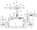
- FIG. 1 is an explanatory diagram showing a configuration of a pump device according to an embodiment of the present invention.
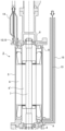
- FIG. 2 is a cross-sectional view of the pump device according to the embodiment of the present invention.
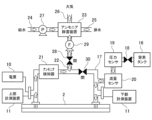
- FIG. 3 is an explanatory diagram showing the flow of nitrogen gas (when the ammonia concentration is less than a threshold value) in the embodiment of the present invention.
- FIG. 4 is an explanatory diagram showing the flow of nitrogen gas (when the ammonia concentration is equal to or higher than a threshold) in the embodiment of the present invention.
- the pump device of the present invention is a pump device that pumps up a liquid fuel material from inside a tank in which a corrosive liquid fuel material is stored, the pump device being made of a material that is corrosion-resistant to the liquid fuel material and including a motor that generates a driving force for the pump device inside the tank, a motor casing that covers the motor, a motor cable that is connected to a power supply device installed outside the tank and supplies power from the power supply device to the motor, a motor cable protective tube that is made of a material that is corrosion-resistant to the liquid fuel material and covers the motor cable inside the tank, tank internal piping that is made of a material that is corrosion-resistant to the liquid fuel material and is connected to the motor casing inside the tank, and a purge gas supply unit that is connected to a purge gas supply unit installed outside the tank.
- the purge gas piping includes a purge gas piping through which the purge gas supplied from flows, a pressure adjustment unit installed in the purge gas piping to keep the pressure inside the purge gas piping constant, a pressure sensor installed in the purge gas piping to detect changes in the pressure of the purge gas inside the purge gas piping, and a flow rate sensor installed in the purge gas piping to detect changes in the flow rate of the purge gas inside the purge gas piping.
- the purge gas piping is connected to the motor cable protection tube and the tank internal piping, and the purge gas supplied from the purge gas supply unit is supplied from the purge gas piping through either the motor cable protection tube or the tank internal piping to the inside of the motor casing, and is returned from the inside of the motor casing to the purge gas piping through the other of the motor cable protection tube or the tank internal piping.
- the pump device is installed inside the tank that stores the corrosive liquid fuel material (e.g., liquid ammonia), but since the motor of the pump device is covered by a motor casing made of a material that is corrosion-resistant to the liquid fuel material (e.g., stainless steel), the pump device can be appropriately protected from corrosion.
- the motor cable that supplies power to the motor of the pump device is also installed inside the tank that stores the corrosive liquid fuel material, but since the motor cable is covered by a motor cable protective tube made of a material that is corrosion-resistant to the liquid fuel material, the motor cable can be appropriately protected from corrosion.
- the purge gas (e.g., nitrogen gas, etc.) supplied from the purge gas supply unit is supplied from the purge gas piping through either the motor cable protection tube or the tank internal piping to the inside of the motor casing, and is returned from the inside of the motor casing through the other of the motor cable protection tube or the tank internal piping to the purge gas piping.
- the purge gas can be circulated using the motor cable protection tube and the tank internal piping, so the inside of the motor casing can be purged more effectively with the purge gas than when the purge gas cannot be circulated. Therefore, even if a liquid fuel material gets into the inside of the motor casing, the pump device can be appropriately protected from corrosion by purging.
- the inside of the motor cable protection tube can also be effectively purged with the purge gas. Therefore, even if a liquid fuel material gets into the inside of the motor casing, the motor cable can be appropriately protected from corrosion by purging.
- the pressure inside the purge gas piping is kept constant by the pressure adjustment unit. If liquid fuel material gets into the motor casing, motor cable protection tube, or tank internal piping, vaporized fuel gas (e.g., ammonia gas) is generated from the liquid fuel material, and the pressure inside the purge gas piping changes.
- the pressure sensor can detect the change in the pressure of the purge gas inside the purge gas piping, making it possible to detect that liquid fuel material has gotten into the motor casing, motor cable protection tube, or tank internal piping.
- the flow sensor can detect the change in the flow rate of the purge gas inside the purge gas piping, making it possible to detect that liquid fuel material has gotten into the motor casing, motor cable protection tube, or tank internal piping.
- the pump device of the present invention may also include a detector that is installed in the purge gas piping and detects whether fuel gas vaporized from the liquid fuel material has entered the inside of the purge gas piping.
- a detector can detect whether or not fuel gas vaporized from the liquid fuel material has gotten into the purge gas piping, making it possible to detect that liquid fuel material has gotten into the motor casing, motor cable protection tube, or tank internal piping.
- the pump device of the present invention may also include a detoxification device that is connected to the purge gas piping and that detoxifies the fuel gas vaporized from the liquid fuel material that has been mixed inside the purge gas piping.
- the decontamination device can decontaminate the fuel gas (such as ammonia gas) that has evaporated from the liquid fuel material that has gotten into the purge gas piping, rendering it harmless.
- the fuel gas such as ammonia gas
- the pump system of the present invention includes a tank for storing a corrosive liquid fuel material, and a pump device for pumping the liquid fuel material from the tank, the pump device being made of a material that is corrosion-resistant to the liquid fuel material and including a motor that generates a driving force for the pump device inside the tank, a motor casing that covers the motor, a motor cable that is connected to a power supply device installed outside the tank and supplies power from the power supply device to the motor, a motor cable protective tube that is made of a material that is corrosion-resistant to the liquid fuel material and covers the motor cable inside the tank, tank internal piping that is made of a material that is corrosion-resistant to the liquid fuel material and is connected to the motor casing inside the tank, and a purge gas supply unit that is installed outside the tank.
- the purge gas supply system includes a purge gas pipe through which purge gas supplied from the purge gas supply unit flows, a pressure adjustment unit installed in the purge gas pipe to keep the pressure inside the purge gas pipe constant, a pressure sensor installed in the purge gas pipe to detect changes in the pressure of the purge gas inside the purge gas pipe, and a flow rate sensor installed in the purge gas pipe to detect changes in the flow rate of the purge gas inside the purge gas pipe.
- the purge gas pipe is connected to the motor cable protection tube and the tank internal piping, and the purge gas supplied from the purge gas supply unit is supplied from the purge gas pipe through either the motor cable protection tube or the tank internal piping to the inside of the motor casing, and is returned from the inside of the motor casing to the purge gas pipe through the other of the motor cable protection tube or the tank internal piping.
- the pump device is installed inside a tank that stores a corrosive liquid fuel material (e.g., liquid ammonia), but since the motor is covered by a motor casing made of a material that is corrosion-resistant to the liquid fuel material (e.g., stainless steel), the pump device can be adequately protected from corrosion.
- the motor cable that supplies power to the motor of the pump device is also installed inside the tank that stores the corrosive liquid fuel material, but since the motor cable is covered by a motor cable protective tube made of a material that is corrosion-resistant to the liquid fuel material, the motor cable can be adequately protected from corrosion.
- the purge gas (such as nitrogen gas) supplied from the purge gas supply unit is supplied from the purge gas piping through either the motor cable protection tube or the tank internal piping to the inside of the motor casing, and is returned from the inside of the motor casing through the other of the motor cable protection tube or the tank internal piping to the purge gas piping.
- the purge gas can be circulated using the motor cable protection tube and the tank internal piping, so the inside of the motor casing can be purged more effectively with the purge gas than when the purge gas cannot be circulated. Therefore, even if a liquid fuel material gets into the inside of the motor casing, the pump device can be appropriately protected from corrosion by purging.
- the inside of the motor cable protection tube can also be effectively purged with the purge gas. Therefore, even if a liquid fuel material gets into the inside of the motor casing, the motor cable can be appropriately protected from corrosion by purging.
- the pressure inside the purge gas piping is kept constant by the pressure adjustment unit. If liquid fuel material gets into the motor casing, motor cable protection tube, or tank internal piping, vaporized fuel gas (such as ammonia gas) is generated from the liquid fuel material, and the pressure inside the purge gas piping changes.
- the pressure sensor can detect the change in purge gas pressure inside the purge gas piping, making it possible to detect that liquid fuel material has gotten into the motor casing, motor cable protection tube, or tank internal piping.
- the flow sensor can detect the change in the flow rate of the purge gas inside the purge gas piping, making it possible to detect that liquid fuel material has gotten into the motor casing, motor cable protection tube, or tank internal piping.
- liquid fuel material gets inside the motor of a pump device, this can be detected and the pump device can be protected from corrosion.
- FIG. 1 is an explanatory diagram showing the configuration of a pump system according to this embodiment
- FIG. 2 is a cross-sectional view of the pump device according to this embodiment.
- the pump system 1 includes a tank 2 that stores liquid ammonia (a corrosive liquid fuel material), and a pump device 3 that is installed inside the tank 2 and pumps up the liquid ammonia.
- liquid ammonia a corrosive liquid fuel material
- the tank 2 includes a tank casing 4 made of a material (e.g., stainless steel) that is resistant to corrosion by liquid ammonia, and the pump device 3 includes a motor casing 5 made of a material (e.g., stainless steel) that is resistant to corrosion by liquid ammonia.
- a tank casing 4 made of a material (e.g., stainless steel) that is resistant to corrosion by liquid ammonia
- the pump device 3 includes a motor casing 5 made of a material (e.g., stainless steel) that is resistant to corrosion by liquid ammonia.
- a motor (stator) 6 that generates the driving force for the pump device 3
- a motor (rotor) 6 a rotating shaft 7 that is rotated by the driving force of the motor (rotor) 6'
- a pair of upper and lower bearings 8 that rotatably support the rotating shaft 7.
- the motor (stator) 6 and the motor (rotor) 6' each have a canned motor structure that is sealed so as not to come into contact with liquid.
- acceleration sensors 9 that measure high-frequency vibrations of the bearings 8 are installed near the pair of upper and lower bearings 8.
- a power supply unit 10 that supplies power to the pump device 3, and two measuring devices 11 (upper measuring device 11 and lower measuring device 11) to which output signals from a pair of upper and lower acceleration sensors 9 are input.
- a motor cable 12 that supplies power from the power supply unit 10 is connected to the motor (stator) 6, and a sensor cable 13 that transmits output signals to the measuring devices 11 (upper measuring device 11 and lower measuring device 11) is connected to each of the pair of upper and lower acceleration sensors 9.
- the motor cable and sensor cable 13 are covered by a motor cable protective tube 14 and a sensor cable protective tube 15, respectively, which are made of a material (such as stainless steel) that is resistant to corrosion by liquid ammonia.
- the sensor cable protective tube 15 can also be called an in-tank piping.
- a nitrogen tank 16 for supplying nitrogen gas, which is a purge gas, and a nitrogen gas pipe 17 through which the nitrogen gas supplied from the nitrogen tank 16 flows.
- the nitrogen tank 16 corresponds to the purge gas supply unit of the present invention
- the nitrogen gas pipe 17 corresponds to the purge gas pipe of the present invention.
- the nitrogen gas pipe 17 is connected to the motor cable protective tube 14 and the sensor cable protective tube 15, and is configured so that the nitrogen gas supplied from the nitrogen tank 16 is supplied from the nitrogen gas pipe 17 through the sensor cable protective tube 15 to the inside of the motor casing 5, and is returned from the inside of the motor casing 5 through the motor cable protective tube 14 to the nitrogen gas pipe 17.
- the nitrogen gas pipe 17 is provided with a pressure adjustment unit 18 that keeps the pressure inside the nitrogen gas pipe 17 constant, a pressure sensor 19 that detects changes in the pressure of the nitrogen gas inside the nitrogen gas pipe 17, and a flow rate sensor 20 that detects changes in the flow rate of the nitrogen gas inside the nitrogen gas pipe 17.
- the pressure adjustment unit 18 can be composed of, for example, a pressure reducing valve.
- the nitrogen gas pipe 17 is also provided with an ammonia detector 21 that detects whether ammonia gas vaporized from liquid ammonia is mixed inside the nitrogen gas pipe 17.
- the ammonia detector 21 can detect that ammonia gas is mixed inside the nitrogen gas pipe 17, for example, when the concentration of ammonia contained in the nitrogen gas in the nitrogen gas pipe 17 becomes equal to or higher than a predetermined threshold value.
- an ammonia abatement pipe 22 for abating ammonia gas is branched off from the nitrogen gas pipe 17.
- the ammonia abatement pipe 22 is connected to an ammonia abatement device 23 that abats ammonia gas vaporized from the liquid ammonia mixed inside the nitrogen gas pipe 17.
- a water supply pipe 24 for supplying water (washing water) used to detoxify the ammonia gas
- a drain pipe 25 for discharging the ammonia water produced by the ammonia gas detoxification
- an exhaust pipe 26 for discharging the nitrogen gas from which the ammonia gas has been removed.
- a water pump 27 is provided on the water supply pipe for sending the water (washing water) used to detoxify the ammonia gas to the ammonia detoxification device 23.
- the ammonia abatement pipe 22 is provided with an automatic valve 28 that is controlled to be open when ammonia gas is being abatement treated, and a blower 29 for sending nitrogen gas mixed with ammonia gas to the ammonia abatement device 23.
- the automatic valve 28 of the ammonia abatement pipe 22 is controlled to be closed when ammonia gas is not being abatement treated.
- the nitrogen gas pipe 17 is provided with an automatic valve 30 that is controlled to be closed when ammonia gas is being abatement treated.
- the automatic valve 30 of the nitrogen gas pipe 17 is controlled to be open when ammonia gas is not being abatement treated.
- FIGS. 3 and 4 are explanatory diagrams showing the flow of nitrogen gas in the pump system 1 of this embodiment.
- the flow of nitrogen gas is indicated by arrows.
- the ammonia detector 21 does not detect that ammonia gas is mixed inside the nitrogen gas pipe 17, that is, when the concentration of ammonia contained in the nitrogen gas in the nitrogen gas pipe 17 is below a predetermined threshold value, the automatic valve 30 of the nitrogen gas pipe 17 is controlled to be open, and the automatic valve 28 of the ammonia abatement pipe 22 is controlled to be closed.
- the ammonia detector 21 detects that ammonia gas has been mixed inside the nitrogen gas pipe 17, that is, if the concentration of ammonia contained in the nitrogen gas in the nitrogen gas pipe 17 is equal to or higher than a predetermined threshold value, the automatic valve 30 in the nitrogen gas pipe 17 is controlled to close, and the automatic valve 28 in the ammonia abatement pipe 22 is controlled to open.
- the pump device 3 is installed inside the tank 2 in which corrosive liquid ammonia is stored, but since the motor (stator) 6 is covered by the motor casing 5 made of a material (e.g., stainless steel) that is corrosion-resistant to liquid ammonia, the pump device 3 can be appropriately protected from corrosion.
- the motor cable 12 that supplies power to the motor 6 of the pump device 3 is also installed inside the tank 2 in which liquid ammonia is stored, but since the motor cable 12 is covered by the motor cable protective tube 14 made of a material that is corrosion-resistant to liquid ammonia, the motor cable 12 can be appropriately protected from corrosion.
- nitrogen gas supplied from the nitrogen tank 16 is supplied from the nitrogen gas pipe 17 to the inside of the motor casing 5 through one of the motor cable protection pipe 14 or the tank internal pipe 15, and is returned from the inside of the motor casing 5 to the nitrogen gas pipe 17 through the other of the motor cable protection pipe 14 or the tank internal pipe 15.
- nitrogen gas can be circulated using the motor cable protection pipe 14 and the tank internal pipe 15, so the inside of the motor casing 5 can be purged more effectively with nitrogen gas than when nitrogen gas cannot be circulated. Therefore, even if liquid ammonia gets into the inside of the motor casing 5, the motor (stator) 6 can be appropriately protected from corrosion by purging.
- the inside of the motor cable protection pipe 14 can also be effectively purged with nitrogen gas. Therefore, even if liquid ammonia gets into the inside of the motor casing 5, the motor cable 12 can be appropriately protected from corrosion by purging.
- the pressure inside the nitrogen gas piping 17 is kept constant by the pressure adjustment unit 18. If liquid ammonia gets into the motor casing 5, the motor cable protection tube 14, or the tank inner piping 15, ammonia gas is vaporized from the liquid ammonia, and the pressure inside the nitrogen gas piping 17 changes.
- the pressure sensor 19 can detect the change in the pressure of the nitrogen gas inside the nitrogen gas piping 17, and thereby it can be detected that liquid ammonia has gotten into the motor casing 5, the motor cable protection tube 14, or the tank inner piping 15.
- the flow sensor 20 can detect the change in the flow rate of nitrogen gas inside the nitrogen gas piping 17, making it possible to detect that liquid ammonia has gotten into the motor casing 5, the motor cable protection tube 14, or the tank internal piping 15.
- the ammonia detector 21 can detect whether ammonia gas vaporized from liquid ammonia has got into the nitrogen gas piping 17, and thus it can detect that liquid ammonia has gotten into the motor casing 5, the motor cable protection tube 14, or the tank inner piping 15.
- the ammonia detoxification device 23 can detoxify the ammonia gas that has evaporated from the liquid ammonia that has gotten into the nitrogen gas piping 17, making it harmless.
- the pump device of the present invention has the effect of being able to detect when liquid fuel material has entered the storage chamber for the pump device's electrical system components and protecting the pump device from corrosion, and is useful as a canned motor pump for liquid ammonia, etc.
Landscapes
- Engineering & Computer Science (AREA)
- Mechanical Engineering (AREA)
- General Engineering & Computer Science (AREA)
- Structures Of Non-Positive Displacement Pumps (AREA)
Abstract
Description
以下、本発明の実施の形態のポンプ装置について、図面を用いて説明する。本実施の形態では、液体アンモニア用のキャンドモータポンプ等として用いられるポンプ装置の場合を例示する。
2 タンク
3 ポンプ装置
4 タンクケーシング
5 モータケーシング
6 モータ(固定子)
6’ モータ(回転子)
7 回転シャフト
8 軸受け
9 加速度センサ(センサ)
10 電源装置
11 計測装置(上部計測装置、下部計測装置)
12 モータケーブル
13 センサケーブル
14 モータケーブル保護管
15 センサケーブル保護管(タンク内配管)
16 窒素タンク(パージガス供給部)
17 窒素ガス配管(パージガス配管)
18 圧力調整部
19 圧力センサ
20 流量センサ
21 アンモニア検知器(検知器)
22 アンモニア除害配管
23 アンモニア除害装置(除害装置)
24 給水菅
25 排水管
26 排気菅
27 送水ポンプ
28 自動弁
29 送風機
30 自動弁
Claims (4)
- 腐食性を有する液体燃料材料が溜められるタンクの内部から前記液体燃料材料を汲み上げるポンプ装置において、
前記ポンプ装置は、
前記液体燃料材料に対して耐腐食性を有する材料で構成され、前記タンクの内部において前記ポンプ装置のモータを覆うモータケーシングと、
前記モータケーシング内に設置され、前記ポンプ装置の駆動力を発生させるモータと、
前記タンクの外部に設置される電源装置に接続され、前記電源装置から前記モータに電力を供給するモータケーブルと、
前記液体燃料材料に対して耐腐食性を有する材料で構成され、前記タンクの内部において前記モータケーブルを覆うモータケーブル保護管と、
前記液体燃料材料に対して耐腐食性を有する材料で構成され、前記タンクの内部において前記モータケーシングに接続されるタンク内配管と、
前記タンクの外部に設置されるパージガス供給部に接続され、前記パージガス供給部から供給されるパージガスが流れるパージガス配管と、
前記パージガス配管に設置され、前記パージガス配管の内部の圧力を一定に保つ圧力調整部と、
前記パージガス配管に設置され、前記パージガス配管の内部における前記パージガスの圧力の変化を検知する圧力センサと、
前記パージガス配管に設置され、前記パージガス配管の内部における前記パージガスの流量の変化を検知する流量センサと、
を備え、
前記パージガス配管は、前記モータケーブル保護管および前記タンク内配管と接続され、前記パージガス供給部から供給されるパージガスが、前記パージガス配管から前記モータケーブル保護管または前記タンク内配管の一方を通って前記モータケーシングの内部に供給され、前記モータケーシングの内部から前記モータケーブル保護管または前記タンク内配管の他方を通って前記パージガス配管に戻されるように構成されている、ポンプ装置。 - 前記パージガス配管に設置され、前記パージガス配管の内部に前記液体燃料材料から気化した燃料ガスが混入しているか否かを検知する検知器を備える、請求項1に記載のポンプ装置。
- 前記パージガス配管に接続され、前記パージガス配管の内部に混入した前記液体燃料材料から気化した燃料ガスを除害処理する除害装置を備える、請求項1または請求項2に記載のポンプ装置。
- 腐食性を有する液体燃料材料が溜められるタンクと、
前記タンクから前記液体燃料材料を汲み上げるポンプ装置と、
を備えるポンプシステムにおいて、
前記ポンプ装置は、
前記液体燃料材料に対して耐腐食性を有する材料で構成され、前記タンクの内部において前記ポンプ装置のモータを覆うモータケーシングと、
前記モータケーシング内に設置され、前記ポンプ装置の駆動力を発生させるモータと、
前記タンクの外部に設置される電源装置に接続され、前記電源装置から前記モータに電力を供給するモータケーブルと、
前記液体燃料材料に対して耐腐食性を有する材料で構成され、前記タンクの内部において前記モータケーブルを覆うモータケーブル保護管と、
前記液体燃料材料に対して耐腐食性を有する材料で構成され、前記タンクの内部において前記モータケーシングに接続されるタンク内配管と、
前記タンクの外部に設置されるパージガス供給部に接続され、前記パージガス供給部から供給されるパージガスが流れるパージガス配管と、
前記パージガス配管に設置され、前記パージガス配管の内部の圧力を一定に保つ圧力調整部と、
前記パージガス配管に設置され、前記パージガス配管の内部における前記パージガスの圧力の変化を検知する圧力センサと、
前記パージガス配管に設置され、前記パージガス配管の内部における前記パージガスの流量の変化を検知する流量センサと、
を備え、
前記パージガス配管は、前記モータケーブル保護管および前記タンク内配管と接続され、前記パージガス供給部から供給されるパージガスが、前記パージガス配管から前記モータケーブル保護管または前記タンク内配管の一方を通って前記モータケーシングの内部に供給され、前記モータケーシングの内部から前記モータケーブル保護管または前記タンク内配管の他方を通って前記パージガス配管に戻されるように構成されている、ポンプシステム。
Applications Claiming Priority (2)
| Application Number | Priority Date | Filing Date | Title |
|---|---|---|---|
| JP2023072206 | 2023-04-26 | ||
| JP2023-072206 | 2023-04-26 |
Publications (1)
| Publication Number | Publication Date |
|---|---|
| WO2024225367A1 true WO2024225367A1 (ja) | 2024-10-31 |
Family
ID=93256749
Family Applications (1)
| Application Number | Title | Priority Date | Filing Date |
|---|---|---|---|
| PCT/JP2024/016205 Ceased WO2024225367A1 (ja) | 2023-04-26 | 2024-04-25 | ポンプ装置およびポンプシステム |
Country Status (2)
| Country | Link |
|---|---|
| TW (1) | TW202443025A (ja) |
| WO (1) | WO2024225367A1 (ja) |
Cited By (1)
| Publication number | Priority date | Publication date | Assignee | Title |
|---|---|---|---|---|
| JP7821363B1 (ja) * | 2025-08-15 | 2026-02-26 | 日機装株式会社 | コラム封止部材およびサブマージドポンプシステム |
Citations (2)
| Publication number | Priority date | Publication date | Assignee | Title |
|---|---|---|---|---|
| JP2013092145A (ja) * | 2011-10-26 | 2013-05-16 | Assoma Inc | 永久磁石モータポンプ |
| JP2019113067A (ja) * | 2017-12-20 | 2019-07-11 | マン・エナジー・ソリューションズ・エスイー | 排ガス再循環送風機及び内燃機関 |
-
2024
- 2024-04-25 WO PCT/JP2024/016205 patent/WO2024225367A1/ja not_active Ceased
- 2024-04-25 TW TW113115369A patent/TW202443025A/zh unknown
Patent Citations (2)
| Publication number | Priority date | Publication date | Assignee | Title |
|---|---|---|---|---|
| JP2013092145A (ja) * | 2011-10-26 | 2013-05-16 | Assoma Inc | 永久磁石モータポンプ |
| JP2019113067A (ja) * | 2017-12-20 | 2019-07-11 | マン・エナジー・ソリューションズ・エスイー | 排ガス再循環送風機及び内燃機関 |
Cited By (1)
| Publication number | Priority date | Publication date | Assignee | Title |
|---|---|---|---|---|
| JP7821363B1 (ja) * | 2025-08-15 | 2026-02-26 | 日機装株式会社 | コラム封止部材およびサブマージドポンプシステム |
Also Published As
| Publication number | Publication date |
|---|---|
| TW202443025A (zh) | 2024-11-01 |
Similar Documents
| Publication | Publication Date | Title |
|---|---|---|
| WO2024225367A1 (ja) | ポンプ装置およびポンプシステム | |
| US8357304B2 (en) | Hazardous material storage and leak mitigation system | |
| JP4214965B2 (ja) | 蒸発燃料処理装置の漏れ検出装置 | |
| ES2740123T3 (es) | Unidad de descontaminación asistida por vacío y transportable, y procedimiento de descontaminación | |
| WO2019044504A1 (ja) | シールシステム | |
| WO2024225373A1 (ja) | ポンプ装置およびポンプシステム | |
| US5151250A (en) | Automatic purge method for ozone generators | |
| CN116529489A (zh) | 流路切换装置以及用于防止潜没式泵的空转的方法 | |
| KR102492784B1 (ko) | 위험 물질용 프로세스 유닛 | |
| KR100673148B1 (ko) | 잠수함 | |
| JP2002156092A (ja) | 水中軸受潤滑システム | |
| US10611562B2 (en) | Liquid storage system and method of supplying nonflammable gases in the same | |
| US20100025258A1 (en) | Hydrogen generating apparatus with hydrogen concentration sensors | |
| JP4508374B2 (ja) | ガス漏れ検知システム | |
| JP5611377B2 (ja) | 液体吸い込み装置 | |
| JP3257450B2 (ja) | 硫化水素除去剤の薬注制御方法及び薬注制御装置 | |
| CN104246131B (zh) | 密封结构、具有密封结构的输送装置以及密封结构的操作方法 | |
| KR100558907B1 (ko) | 수중항해중의 배기배출구조를 갖는 잠수함 | |
| KR102584151B1 (ko) | 선박의 암모니아처리시스템 | |
| TW202511619A (zh) | 泵浦裝置及泵浦系統 | |
| JP5868229B2 (ja) | オゾンを用いた有機物分解システム | |
| JP4009566B2 (ja) | 溶存酸素低減装置 | |
| JP2025523840A (ja) | 接続スペース及び水素供給装置 | |
| JP2001193122A (ja) | 水封式ドレンタンク圧力調整装置 | |
| JP2006196265A (ja) | パッケージ型発電装置とその換気制御方法 |
Legal Events
| Date | Code | Title | Description |
|---|---|---|---|
| 121 | Ep: the epo has been informed by wipo that ep was designated in this application |
Ref document number: 24797112 Country of ref document: EP Kind code of ref document: A1 |
|
| WWE | Wipo information: entry into national phase |
Ref document number: 202517114170 Country of ref document: IN |
|
| NENP | Non-entry into the national phase |
Ref country code: DE |
|
| WWP | Wipo information: published in national office |
Ref document number: 202517114170 Country of ref document: IN |
|
| 122 | Ep: pct application non-entry in european phase |
Ref document number: 24797112 Country of ref document: EP Kind code of ref document: A1 |