WO2024225018A1 - 二次電池用正極および二次電池 - Google Patents
二次電池用正極および二次電池 Download PDFInfo
- Publication number
- WO2024225018A1 WO2024225018A1 PCT/JP2024/014361 JP2024014361W WO2024225018A1 WO 2024225018 A1 WO2024225018 A1 WO 2024225018A1 JP 2024014361 W JP2024014361 W JP 2024014361W WO 2024225018 A1 WO2024225018 A1 WO 2024225018A1
- Authority
- WO
- WIPO (PCT)
- Prior art keywords
- positive electrode
- region
- mixture layer
- length
- negative electrode
- Prior art date
- Legal status (The legal status is an assumption and is not a legal conclusion. Google has not performed a legal analysis and makes no representation as to the accuracy of the status listed.)
- Ceased
Links
Images


Classifications
-
- H—ELECTRICITY
- H01—ELECTRIC ELEMENTS
- H01M—PROCESSES OR MEANS, e.g. BATTERIES, FOR THE DIRECT CONVERSION OF CHEMICAL ENERGY INTO ELECTRICAL ENERGY
- H01M10/00—Secondary cells; Manufacture thereof
- H01M10/04—Construction or manufacture in general
-
- H—ELECTRICITY
- H01—ELECTRIC ELEMENTS
- H01M—PROCESSES OR MEANS, e.g. BATTERIES, FOR THE DIRECT CONVERSION OF CHEMICAL ENERGY INTO ELECTRICAL ENERGY
- H01M10/00—Secondary cells; Manufacture thereof
- H01M10/05—Accumulators with non-aqueous electrolyte
- H01M10/058—Construction or manufacture
- H01M10/0587—Construction or manufacture of accumulators having only wound construction elements, i.e. wound positive electrodes, wound negative electrodes and wound separators
-
- H—ELECTRICITY
- H01—ELECTRIC ELEMENTS
- H01M—PROCESSES OR MEANS, e.g. BATTERIES, FOR THE DIRECT CONVERSION OF CHEMICAL ENERGY INTO ELECTRICAL ENERGY
- H01M4/00—Electrodes
- H01M4/02—Electrodes composed of, or comprising, active material
- H01M4/13—Electrodes for accumulators with non-aqueous electrolyte, e.g. for lithium-accumulators; Processes of manufacture thereof
- H01M4/134—Electrodes based on metals, Si or alloys
-
- H—ELECTRICITY
- H01—ELECTRIC ELEMENTS
- H01M—PROCESSES OR MEANS, e.g. BATTERIES, FOR THE DIRECT CONVERSION OF CHEMICAL ENERGY INTO ELECTRICAL ENERGY
- H01M4/00—Electrodes
- H01M4/02—Electrodes composed of, or comprising, active material
- H01M4/36—Selection of substances as active materials, active masses, active liquids
- H01M4/38—Selection of substances as active materials, active masses, active liquids of elements or alloys
-
- Y—GENERAL TAGGING OF NEW TECHNOLOGICAL DEVELOPMENTS; GENERAL TAGGING OF CROSS-SECTIONAL TECHNOLOGIES SPANNING OVER SEVERAL SECTIONS OF THE IPC; TECHNICAL SUBJECTS COVERED BY FORMER USPC CROSS-REFERENCE ART COLLECTIONS [XRACs] AND DIGESTS
- Y02—TECHNOLOGIES OR APPLICATIONS FOR MITIGATION OR ADAPTATION AGAINST CLIMATE CHANGE
- Y02E—REDUCTION OF GREENHOUSE GAS [GHG] EMISSIONS, RELATED TO ENERGY GENERATION, TRANSMISSION OR DISTRIBUTION
- Y02E60/00—Enabling technologies; Technologies with a potential or indirect contribution to GHG emissions mitigation
- Y02E60/10—Energy storage using batteries
-
- Y—GENERAL TAGGING OF NEW TECHNOLOGICAL DEVELOPMENTS; GENERAL TAGGING OF CROSS-SECTIONAL TECHNOLOGIES SPANNING OVER SEVERAL SECTIONS OF THE IPC; TECHNICAL SUBJECTS COVERED BY FORMER USPC CROSS-REFERENCE ART COLLECTIONS [XRACs] AND DIGESTS
- Y02—TECHNOLOGIES OR APPLICATIONS FOR MITIGATION OR ADAPTATION AGAINST CLIMATE CHANGE
- Y02P—CLIMATE CHANGE MITIGATION TECHNOLOGIES IN THE PRODUCTION OR PROCESSING OF GOODS
- Y02P70/00—Climate change mitigation technologies in the production process for final industrial or consumer products
- Y02P70/50—Manufacturing or production processes characterised by the final manufactured product
Definitions
- This disclosure relates to a positive electrode for a secondary battery and a secondary battery, and more specifically to a positive electrode constituting a wound electrode body and a secondary battery including the electrode body.
- the positive electrode constituting the wound electrode body comprises a long positive electrode core and a positive electrode mixture layer disposed on both sides of the positive electrode core (see, for example, Patent Document 1).
- Patent Document 1 discloses an electrode plate in which multiple grooves are formed on the surface of the mixture layer.
- secondary batteries such as lithium ion batteries
- the volume of the electrode body changes significantly with charging and discharging, and for example, the electrode plate core expands in the width direction, causing plastic deformation of the core, which can result in a short circuit.
- insulation measures are taken, such as placing insulating plates between the electrode body and the lead, sealing body, bottom of the outer can, etc.
- the positive electrode for a secondary battery is a positive electrode for a secondary battery comprising an elongated positive electrode core and a positive electrode mixture layer disposed on both sides of the positive electrode core, the positive electrode mixture layer including a first region and a second region thinner than the first region, the thickness of the second region being 20% to 98% of the average thickness of the first region, and the second region being provided with a length of 8% or more of the length of the positive electrode mixture layer from one end in the longitudinal direction of the positive electrode mixture layer.
- the secondary battery according to the present disclosure includes the above-mentioned positive electrode, a negative electrode, and a separator, and is equipped with an electrode assembly in which the positive electrode and the negative electrode are wound with the separator interposed therebetween, and the positive electrode is arranged so that the second region is located on the winding core side of the electrode assembly.
- the secondary battery positive electrode disclosed herein can effectively suppress plastic deformation of the electrode plate that occurs during charging and discharging of the battery.
- FIG. 2 is an axial cross-sectional view of a cylindrical battery according to an embodiment of the present invention.
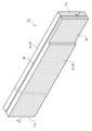
- FIG. 2 is a perspective view of a positive electrode according to an embodiment of the present invention.
- 3 is a cross-sectional view taken along line AA in FIG. 2.
- FIG. 2 is a cross-sectional view of a positive electrode which is another example of the embodiment.
- a cylindrical battery 10 in which a wound electrode body 14 is housed in a cylindrical exterior can 16 with a bottom is exemplified, but the exterior body of the battery is not limited to a cylindrical exterior can.
- Other embodiments of the nonaqueous electrolyte secondary battery according to the present disclosure include a prismatic battery with a prismatic exterior can, a pouch-type battery with an exterior body composed of a laminate sheet including a metal layer and a resin layer, etc.
- FIG. 1 is a cross-sectional view of a cylindrical battery 10 according to an embodiment.
- the cylindrical battery 10 has a positive electrode 11, a negative electrode 12, and a separator 13, and is provided with an electrode assembly 14 in which the positive electrode 11 and the negative electrode 12 are wound with the separator 13 interposed therebetween.
- the cylindrical battery 10 also has a cylindrical outer can 16 with a bottom that houses the electrode assembly 14, and a sealing body 17 that closes the opening of the outer can 16.
- the outer can 16 houses an electrolyte together with the electrode assembly 14.
- the outer can 16 has a grooved portion 22 formed in its side wall, and the sealing body 17 is supported by the grooved portion 22 to close the opening of the outer can 16.
- the sealing body 17 side of the cylindrical battery 10 is referred to as the top
- the bottom side of the outer can 16 is referred to as the bottom.
- the positive electrode mixture layer 31 constituting the positive electrode 11 includes a first region 32 and a thin portion 33 (see FIG. 2, etc.), which is a second region thinner than the first region 32.
- the thin portion 33 is preferably located on the winding core side of the electrode body 14. According to the cylindrical battery 10, by using the positive electrode 11 including the thin portion 33, plastic deformation of the electrode plate accompanying charging and discharging of the battery is effectively suppressed. It is believed that the provision of the specific thin portion 33 can effectively alleviate the stress acting on the electrode plate during charging and discharging, and plastic deformation of not only the positive electrode 11 but also the negative electrode 12 is suppressed.
- the electrolyte may be an aqueous electrolyte, but in this embodiment, a non-aqueous electrolyte is used.
- the non-aqueous electrolyte has lithium ion conductivity.
- the non-aqueous electrolyte may be a liquid electrolyte (electrolytic solution) or a solid electrolyte.
- the cylindrical battery 10 is, for example, a non-aqueous electrolyte secondary battery, and is preferably a lithium ion battery.
- the liquid electrolyte includes a non-aqueous solvent and an electrolyte salt dissolved in the non-aqueous solvent.
- a non-aqueous solvent for example, esters, ethers, nitriles, amides, and mixed solvents of two or more of these are used as the non-aqueous solvent.
- the non-aqueous solvent include ethylene carbonate (EC), ethyl methyl carbonate (EMC), dimethyl carbonate (DMC), diethyl carbonate (DEC), and mixed solvents of these.
- the non-aqueous solvent may contain a halogen-substituted product (e.g., fluoroethylene carbonate, etc.) in which at least a part of the hydrogen of these solvents is replaced with a halogen atom such as fluorine.
- a halogen-substituted product e.g., fluoroethylene carbonate, etc.
- a lithium salt such as LiPF6 is used as the electrolyte salt.
- the solid electrolyte for example, a solid or gel-like polymer electrolyte, an inorganic solid electrolyte, etc. can be used.
- the inorganic solid electrolyte a material known in all-solid-state lithium ion secondary batteries, etc. (for example, an oxide-based solid electrolyte, a sulfide-based solid electrolyte, a halogen-based solid electrolyte, etc.) can be used.
- the polymer electrolyte includes, for example, a lithium salt and a matrix polymer, or a non-aqueous solvent, a lithium salt, and a matrix polymer.
- the matrix polymer for example, a polymer material that absorbs a non-aqueous solvent and gels is used.
- the polymer material for example, a fluororesin, an acrylic resin, a polyether resin, etc. can be used.
- the positive electrode 11, negative electrode 12, and separator 13 that make up the electrode body 14 are all long, strip-shaped bodies that are wound in a spiral shape and stacked alternately in the radial direction of the electrode body 14.
- the negative electrode 12 is formed to be slightly larger than the positive electrode 11 in order to prevent lithium precipitation. That is, the negative electrode 12 is formed to be longer in the longitudinal and transverse directions than the positive electrode 11.
- the separator 13 is formed to be at least slightly larger than the positive electrode 11, and for example, two separators 13 are arranged to sandwich the positive electrode 11.
- the electrode body 14 has a positive electrode lead 20 connected to the positive electrode 11 by welding or the like, and a negative electrode lead 21 connected to the negative electrode 12 by welding or the like.
- Insulating plates 18, 19 are arranged above and below the electrode body 14.
- the positive electrode lead 20 passes through a through hole in the insulating plate 18 and extends toward the sealing body 17, and the negative electrode lead 21 passes outside the insulating plate 19 and extends toward the bottom side of the outer can 16.
- the positive electrode lead 20 is connected to the underside of the internal terminal plate 23 of the sealing body 17 by welding or the like, and the cap 27, which is the top plate of the sealing body 17 and is electrically connected to the internal terminal plate 23, serves as the positive electrode terminal.
- the negative electrode lead 21 is connected to the inner bottom surface of the outer can 16 by welding or the like, and the outer can 16 serves as the negative electrode terminal.
- the negative electrode 12 may be disposed on the outer peripheral surface of the electrode body 14, and an exposed portion may be provided in which the surface of the negative electrode core 40 constituting the negative electrode 12 is exposed. In this case, the exposed portion may be in contact with the inner peripheral surface of the outer can 16, and the negative electrode 12 and the outer can 16 may be electrically connected.
- a gasket 28 is provided between the exterior can 16 and the sealing body 17 to ensure airtightness inside the battery.
- the gasket 28 also functions as an insulating member that prevents electrical contact between the exterior can 16 and the sealing body 17.
- the exterior can 16 is formed with a grooved portion 22 that supports the sealing body 17, with part of the side surface protruding inward.
- the grooved portion 22 is preferably formed in an annular shape along the circumferential direction of the exterior can 16, and supports the sealing body 17 on its upper surface.
- the sealing body 17 is fixed to the top of the exterior can 16 by the grooved portion 22 and the open end of the exterior can 16 that is crimped against the sealing body 17.
- the sealing body 17 has a structure in which, in order from the electrode body 14 side, an internal terminal plate 23, a lower valve body 24, an insulating member 25, an upper valve body 26, and a cap 27 are stacked.
- Each member constituting the sealing body 17 has, for example, a disk or ring shape, and each member except for the insulating member 25 is electrically connected to each other.
- the lower valve body 24 and the upper valve body 26 are connected at their respective centers, and the insulating member 25 is interposed between their respective peripheral edges.
- the positive electrode 11 includes a positive electrode core 30 and a positive electrode mixture layer 31 disposed on the positive electrode core 30.
- a foil of a metal stable in the potential range of the positive electrode 11, such as aluminum, an aluminum alloy, stainless steel, or titanium, or a film having the metal disposed on the surface layer can be used.
- the positive electrode mixture layer 31 contains a positive electrode active material, a conductive agent, and a binder, and is preferably provided on both sides of the positive electrode core 30.
- a protective layer containing inorganic particles and a binder may be disposed between the positive electrode core 30 and the positive electrode mixture layer 31, or on the positive electrode mixture layer 31.
- the positive electrode 11 can be produced, for example, by applying a positive electrode mixture slurry containing a positive electrode active material, a conductive agent, and a binder onto the positive electrode core 30, drying the coating, and then compressing it to form a positive electrode mixture layer 31 on both sides of the positive electrode core 30.
- a positive electrode mixture slurry containing a positive electrode active material, a conductive agent, and a binder onto the positive electrode core 30, drying the coating, and then compressing it to form a positive electrode mixture layer 31 on both sides of the positive electrode core 30.
- NMP N-methyl-2-pyrrolidone
- the positive electrode mixture slurry is applied to the entire area of both sides of the positive electrode core 30 except for the part where the positive electrode lead 20 is connected.
- the thin part 33 of the positive electrode mixture layer 31 may be formed by controlling the application method of the positive electrode mixture slurry, or may be formed by forming the positive electrode mixture layer 31 and then peeling off a part of it.
- the positive electrode active material is a lithium transition metal composite oxide containing transition metal elements such as Ni, Co, and Mn.
- Metal elements contained in the lithium transition metal composite oxide include Ni, Co, Mn, Al, Be, B, Na, Mg, Si, K, Ca, Sc, Ti, V, Cr, Fe, Cu, Zn, Ga, Sr, Y, Zr, Nb, Mo, In, Sn, Sb, Ba, Ta, W, Pb, and Bi. Among them, it is preferable to contain at least one of Ni, Co, and Mn.
- suitable composite oxides include lithium transition metal composite oxides containing Ni, Co, and Mn, and lithium transition metal composite oxides containing Ni, Co, and Al. The lithium transition metal composite oxides may be used alone or in combination.
- the lithium transition metal composite oxide has, for example, a layered rock salt structure.
- layered rock salt structures include a layered rock salt structure belonging to space group R-3m and a layered rock salt structure belonging to space group C2/m. Among them, from the viewpoints of high capacity and stability of the crystal structure, a layered rock salt structure belonging to space group R-3m is preferred.
- the content of the positive electrode active material is, for example, 90% to 99% of the mass of the positive electrode mixture layer 31. From the viewpoint of high capacity of the battery, the density of the positive electrode mixture layer 31 is preferably 3.3 g/cc or more, and as an example, is 3.3 cc to 3.8 g/cc.
- Examples of the conductive agent contained in the positive electrode mixture layer 31 include carbon black such as acetylene black and ketjen black, graphite, carbon nanotubes (CNT), carbon nanofibers, graphene, metal fibers, metal powder, conductive whiskers, etc.
- carbon black such as acetylene black and ketjen black
- graphite carbon nanotubes (CNT)
- carbon nanofibers graphene
- metal fibers metal powder
- conductive whiskers conductive whiskers
- One type of conductive agent may be used alone, or multiple types may be used in combination.
- the content of the conductive agent is, for example, 0.1% to 5% of the mass of the positive electrode mixture layer 31.
- binder contained in the positive electrode mixture layer 31 examples include fluorine-containing resins such as polytetrafluoroethylene (PTFE) and polyvinylidene fluoride (PVDF), olefin resins such as polyethylene, polypropylene, ethylene-propylene-isoprene copolymer, and ethylene-propylene-butadiene copolymer, and acrylic resins such as polyacrylonitrile (PAN), polyimide, polyamide, and ethylene-acrylic acid copolymer. These resins may also be used in combination with carboxymethylcellulose (CMC) or a salt thereof, polyethylene oxide (PEO), and the like.
- CMC carboxymethylcellulose
- PEO polyethylene oxide
- One type of binder may be used alone, or multiple types may be used in combination.
- the content of the binder is, for example, 0.1% to 5% of the mass of the positive electrode mixture layer 31.
- FIG. 1 is a perspective view of the positive electrode 11, and Figure 3 is a cross-sectional view taken along line AA in Figure 2.
- the positive electrode mixture layer 31 includes a first region 32 and a thin portion 33, which is a second region thinner than the first region 32.
- the average thickness of the thin portion 33 is 20% to 98% of the average thickness T of the first region 32.
- the thin portion 33 is formed in a portion of the positive electrode mixture layer 31, and from the viewpoint of increasing the capacity of the battery, it is preferable that the area of the thin portion 33 is smaller than that of the first region 32.
- the thickness T of the first region 32 is preferably substantially constant throughout its entire area, but may have a thickness difference of, for example, about 1%.
- the average thickness T of the first region 32 is preferably 10 ⁇ m or more and 150 ⁇ m or less on one side of the positive electrode core 30, and more preferably 50 ⁇ m or more and 120 ⁇ m or less. In addition, it is preferable that the thickness of the first region 32 is substantially the same on both sides of the positive electrode core 30.
- the thickness T 33 of the thin portion 33 may be substantially constant throughout its entire area, and may have a step between the first region 32 and the thin portion 33, as shown in FIG. 3, where the thickness changes sharply. Alternatively, the thickness T 33 of the thin portion 33 may gradually increase toward the first region 32 or toward both ends of the thin portion 33 in the longitudinal direction. The region where the thickness of the thin portion 33 gradually increases may be formed in a step shape, or may be a gentle slope without a step. The densities of the first region 32 and the thin portion 33 may be different from each other, but are substantially the same in this embodiment.
- the average thickness T 33 of the thin portion 33 is more preferably 40% to 90% of the average thickness T of the first region 32, and particularly preferably 50% to 85%. If the average thickness T 33 is within this range, the electrode plate deformation can be efficiently suppressed while maintaining a high capacity.
- the positive electrode mixture layer 31 is formed on the entire area of both sides of the positive electrode core 30 except for the portion where the positive electrode lead 20 is connected.
- the positive electrode lead 20 is connected, for example, to the center of the positive electrode 11 in the longitudinal direction.
- a core exposed portion where the surface of the positive electrode core 30 is exposed is provided in the center of the positive electrode 11 in the longitudinal direction.
- the length L of the positive electrode mixture layer 31 means the length of the positive electrode mixture layer 31 along the longitudinal direction of the positive electrode 11.
- the length L of the positive electrode mixture layer 31 is approximately the same as the length of the positive electrode 11 and the positive electrode core 30, but more precisely, it is the length obtained by subtracting the length of the core exposed portion from the length of the positive electrode core 30.
- the thin portion 33 is provided with a length L33 that is 8% or more of the length L of the positive electrode mixture layer 31 from a starting end 11x, which is one end in the longitudinal direction of the positive electrode mixture layer 31.
- the length L33 of the thin portion 33 means the length of the thin portion 33 along the longitudinal direction of the positive electrode 11.
- the starting end 11x is the longitudinal end of the positive electrode mixture layer 31 that is located on the winding core side of the electrode body 14. In this embodiment, the winding start end of the positive electrode 11 and the starting end 11x of the positive electrode mixture layer 31 coincide with each other.
- the thin-walled portion 33 is thought to form a minute space between the positive electrode 11 and the negative electrode 12, absorbing the expansion of the negative electrode 12 and relieving the stress caused by the expansion.
- the thin-walled portion 33 also reduces the expansion of the negative electrode 12 itself during charging to a certain extent. As a result, the expansion of the electrode plate in the width direction is suppressed, and insulation measures can be simplified, for example, by omitting insulating plates arranged above and below the electrode body 14.
- the length L33 of the thin portion 33 is preferably 10% or more of the length L of the positive electrode mixture layer 31, more preferably 15% or more, and particularly preferably 18% or more.
- the length L 33 of the thin portion 33 is, for example, 70% or less of the length L of the positive electrode mixture layer 31, more preferably 50% or less, and particularly preferably 40% or less. If the length L 33 of the thin portion 33 is too long, the effect of suppressing plate deformation will plateau while the capacity will be significantly reduced, so the length L 33 of the thin portion 33 is particularly preferably 40% or less of the length L, and may be 35% or less.
- An example of a suitable range of the length L 33 is 10% or more and 40% or less, or 15% or more and 35% or less of the length L. If the length L 33 is within this range, the plate deformation can be efficiently suppressed while maintaining a high capacity.
- the length L 33 of the thin portion 33 is, for example, 70 mm or more and 300 mm or less, more preferably 100 mm or more and 300 mm or less, and particularly preferably 120 mm or more and 250 mm or less.
- the thin portion 33 has a length of, for example, 3.5 to 15 turns of the winding structure of the electrode body 14 from the winding start end (starting end 11x) of the positive electrode 11, more preferably 5 to 10 turns. In this case, the effect of providing the thin portion 33 becomes more remarkable.
- An example of the length L of the positive electrode mixture layer 31 is 600 mm or more and 900 mm or less.
- the thin portion 33 may be formed in a part of the width direction of the positive electrode 11, but is preferably formed over the entire width of the positive electrode 11. However, L33 of the thin portion 33 along the length direction of the positive electrode 11 is preferably longer than the length (width) of the thin portion 33 along the width direction of the positive electrode 11.
- An example of the width of the positive electrode 11 is 50 mm or more and 65 mm or less.
- the thin portion 33 is formed on only one side of the positive electrode 11.
- the thin portion 33 is formed on only one side of the positive electrode 11, it is preferable that the thin portion 33 is formed only on the outer surface of the positive electrode 11 facing the outside of the electrode body 14.
- the mixture layer on the inner side of the negative electrode 12, which faces the outer surface of the positive electrode 11, is thought to be more easily densified than the mixture layer on the outer side of the roll, and therefore undergoes a larger volume change during charging and discharging. For this reason, when the thin portion 33 is formed only on the positive electrode mixture layer 31 on the outer side of the roll of the positive electrode 11, plate deformation can be efficiently suppressed while maintaining a high capacity.
- the entire area of the positive electrode mixture layer 31 on the inner surface of the winding of the positive electrode 11 facing inward of the electrode body 14 is a first region 32 having a substantially constant thickness, and a thin portion 33 is formed only within a predetermined length range from the starting end 11x of the positive electrode mixture layer 31 on the outer surface of the winding.
- FIG. 4 is a cross-sectional view showing another example of the embodiment.
- the positive electrode 11 may have thin-walled portions 33 on both sides of the positive electrode core 30.
- the thin-walled portions 33 are formed on both the outer and inner winding surfaces in a length range from the start end 11x of the positive electrode mixture layer 31 to 8% or more of the length L of the positive electrode mixture layer 31.
- the capacity is reduced compared to when the thin-walled portions 33 are provided only on the outer winding surface of the positive electrode 11 (the embodiment shown in FIG. 2 and FIG. 3), but the same or greater effect of suppressing plate deformation can be obtained.
- the thickness T 33 and length L 33 of the thin portion 33 may be substantially the same or different on both sides of the positive electrode 11.
- the thickness T 33 and length L 33 are different for each thin portion 33, it is preferable that the thickness T 33 and length L 33 of the thin portion 33 located on the outer side of the winding are larger than the thickness T 33 and length L 33 of the thin portion 33 located on the inner side of the winding. In this case, the electrode plate deformation can be efficiently suppressed while maintaining a high capacity.
- the thin portion 33 may be formed in the positive electrode 11, for example, by applying a smaller amount of positive electrode mixture slurry to the area where the thin portion 33 is to be disposed than to other areas.
- the thickness of the first region 32 and the thin portion 33 can be controlled to a desired range by adjusting the amount of positive electrode mixture slurry applied.
- a constant amount of positive electrode mixture slurry may be applied over the entire length of the positive electrode core 30, and then a portion of the coating film may be peeled off within a predetermined length range to form the thin portion 33.
- the positive electrode 11 When preparing the electrode body 14, the positive electrode 11 is positioned so that the thin portion 33 is located on the winding core side of the electrode body 14, and the electrode plate and separator 13 are wound. This forms the thin portion 33 from the starting end 11x on the winding start side of the positive electrode 11. When the thin portion 33 exists on only one side of the positive electrode 11, it is preferable to position the positive electrode 11 so that the thin portion 33 is located on the outer winding surface.
- the negative electrode 12 has a negative electrode core and a negative electrode mixture layer disposed on the negative electrode core.
- a foil of a metal stable in the potential range of the negative electrode 12, such as copper, copper alloy, stainless steel, nickel, or nickel alloy, or a film having the metal disposed on the surface can be used.
- the negative electrode mixture layer 41 contains a negative electrode active material and a binder, and is preferably provided on both sides of the negative electrode core except for the part to which the negative electrode lead 21 is connected.
- a protective layer containing inorganic particles and a binder may be disposed between the negative electrode core and the negative electrode mixture layer, or on the negative electrode mixture layer.
- the negative electrode 12 can be produced, for example, by applying a negative electrode mixture slurry containing a negative electrode active material and a binder to the surface of the negative electrode core, drying the coating, and then compressing it to form a negative electrode mixture layer on both sides of the negative electrode core.
- the binder contained in the negative electrode mixture layer may be fluororesin, olefin resin, PAN, polyimide, polyamide, acrylic resin, etc., but polyvinyl acetate, styrene-butadiene rubber (SBR), etc. may also be used. Of these, it is preferable to use SBR.
- SBR styrene-butadiene rubber
- One type of binder may be used alone, or multiple types may be used in combination.
- the negative electrode mixture layer contains CMC or a salt thereof, polyacrylic acid (PAA) or a salt thereof, polyvinyl alcohol (PVA), etc.
- the content of the binder is, for example, 0.1% or more and 5% or less of the mass of the negative electrode mixture layer.
- the negative electrode mixture layer may contain a conductive agent such as CNT.
- a carbon material that reversibly absorbs and releases lithium ions is generally used as the negative electrode active material.
- the carbon material that functions as the negative electrode active material include natural graphite, artificial graphite, and a mixture of these.
- the negative electrode active material may be an element that alloys with Li, such as Si or Sn, or a material that contains the element. Among these, a silicon-containing material that contains Si is preferable.
- lithium titanate which has a higher charge/discharge potential with respect to metallic lithium than carbon materials, may also be used as the negative electrode active material.
- One type of negative electrode active material may be used alone, or multiple types may be used in combination.
- the content of the negative electrode active material is, for example, 90% to 99.5% of the mass of the negative electrode mixture layer.
- the negative electrode 12 contains a silicon-containing material as the negative electrode active material.
- the content of the silicon-containing material is preferably 6% or more of the total mass of the negative electrode active material, more preferably 8% or more, and particularly preferably 10% or more.
- the configuration of the cylindrical battery 10 having the positive electrode 11 including the thin-walled portion 33 is particularly suitable when using a negative electrode 12 that contains a silicon-containing material and has a large volume change during charging and discharging.
- the upper limit of the content of the silicon-containing material is preferably 80% of the total mass of the negative electrode active material, more preferably 70%, and particularly preferably 60%.
- the silicon-containing material that functions as the negative electrode active material may be any material that contains Si, and examples include silicon alloys, silicon compounds, and composite materials containing Si. Among these, composite materials containing Si are preferred.
- a suitable silicon-containing material is a composite particle that contains an ion-conducting phase and a Si phase dispersed in the ion-conducting phase.
- the Si phase is composed of Si dispersed in the form of fine particles.
- the ion-conducting phase is, for example, at least one selected from a silicate phase, a carbon phase, a silicide phase, and a silicon oxide phase, and may contain at least one element selected from the first and second group elements of the periodic table.
- the ion-conducting phase is a continuous phase composed of a collection of particles finer than the Si phase.
- the composite material may have a conductive layer covering the surface of the ion-conducting phase.
- the conductive layer is made of a material that is more conductive than the ion-conducting phase, and forms a good conductive path in the negative electrode mixture layer.
- the conductive layer is, for example, a carbon coating made of a conductive carbon material. Examples of the conductive carbon material that can be used include carbon black such as acetylene black and ketjen black, graphite, and amorphous carbon (amorphous carbon) with low crystallinity.
- the thickness of the conductive layer is preferably 1 nm or more and 200 nm or less, or 5 nm or more and 100 nm or less, taking into consideration ensuring conductivity and the diffusibility of Li ions into the inside of the particles.
- An example of a suitable composite material containing Si is a composite particle having a sea-island structure in which fine Si particles are substantially uniformly dispersed in an amorphous silicon oxide phase, and which is generally represented by the general formula SiO x (0 ⁇ x ⁇ 2).
- the main component of the silicon oxide may be silicon dioxide.
- the silicon oxide phase may be doped with Li.
- the content ratio (x) of oxygen to Si is, for example, 0.5 ⁇ x ⁇ 2.0, and preferably 0.8 ⁇ x ⁇ 1.5.
- a suitable composite material containing Si is a composite particle having a sea-island structure in which fine Si particles are substantially uniformly dispersed in an amorphous silicate phase.
- a suitable silicate phase is a lithium silicate phase containing Li.
- a suitable composite material containing Si is a composite particle having an island structure in which fine Si particles are dispersed uniformly in the carbon phase.
- the carbon phase is preferably an amorphous carbon phase.
- the carbon phase may contain crystalline components, but preferably contains more amorphous components.
- the composite material may contain particles whose ion-conducting phase is an amorphous carbon phase.
- the amorphous carbon phase is, for example, composed of a carbon material whose average interplanar spacing of (002) planes exceeds 0.34 nm as measured by X-ray diffraction.
- the composite material containing a carbon phase may or may not have a conductive layer separate from the carbon phase.
- a porous sheet having ion permeability and insulation is used for the separator 13.
- the porous sheet include a microporous thin film, a woven fabric, and a nonwoven fabric.
- the material of the separator 13 is preferably a polyolefin such as polyethylene or polypropylene, or cellulose.
- the separator 13 may have a single layer structure or a multilayer structure.
- the separator 13 may have, for example, a multilayer structure including a thermoplastic resin layer such as a polyolefin and a cellulose fiber layer, a two-layer structure of polyethylene (PE)/polypropylene (PP), or a three-layer structure of PE/PP/PE.
- a filler layer containing an inorganic filler may be disposed at the interface between the separator 13 and at least one of the positive electrode 11 and the negative electrode 12.
- inorganic fillers include oxides containing metal elements such as Ti, Al, Si, and Mg, and phosphate compounds.
- the filler layer can be formed by applying a slurry containing the filler to the surface of the positive electrode 11, the negative electrode 12, or the separator 13.
- a resin layer (heat-resistant layer) having high heat resistance such as aramid resin may be disposed on the surface of the separator 13.
- the separator 13 may have, for example, a substrate made of a porous sheet, and a filler layer or a heat-resistant layer disposed on the substrate.
- Example 1 [Preparation of Positive Electrode] Lithium nickel oxide (LiNi 0.88 Co 0.09 Al 0.03 O 2 ) containing cobalt and aluminum was used as the positive electrode active material.
- the positive electrode active material, acetylene black, and polyvinylidene fluoride were mixed in a solid content mass ratio of 98:1:1, and a positive electrode mixture slurry was prepared using N-methylpyrrolidone (NMP) as a dispersion medium.
- NMP N-methylpyrrolidone
- the slurry was applied to both sides of a positive electrode core made of a long aluminum foil with a thickness of 15 ⁇ m, and the coating was dried and compressed to form a positive electrode mixture layer (average thickness on one side: 90 ⁇ m, density: 3.6 g/cm 3 ) on both sides of the positive electrode core.
- a core exposed portion to which a positive electrode lead is connected was left in the center of the length direction of the positive electrode core, and a positive electrode mixture layer was formed over the entire area of the positive electrode core except for the exposed portion.
- a portion of one of the positive electrode mixture layers was peeled off in a length range of 11% (80 mm) of the length of the positive electrode mixture layer from one end in the longitudinal direction of the positive electrode mixture layer, to obtain a positive electrode having a thin-walled portion with a thickness of 85% of the average thickness of the other region (first region) of the positive electrode mixture layer.
- the thickness of the thin-walled portion was approximately constant, at 76.5 ⁇ m ⁇ 0.5 ⁇ m.
- An aluminum positive electrode lead was ultrasonically welded to the exposed core portion of the positive electrode.
- a mixture of graphite powder and a Si-containing material in a mass ratio of 90:10 was used as the negative electrode active material.
- the negative electrode active material, a dispersion of styrene butadiene rubber, and sodium carboxymethylcellulose were mixed in a solid content mass ratio of 98:1:1, and a negative electrode mixture slurry was prepared using water as a dispersion medium.
- the slurry was applied to both sides of a negative electrode core made of a long copper foil with a thickness of 8 ⁇ m, and the coating was dried and compressed to obtain a negative electrode in which a negative electrode mixture layer (average thickness on one side: 94 ⁇ m, density: 1.6 g/cm 3 ) was formed on both sides of the negative electrode core.
- a core exposed portion was left at the end in the length direction of the negative electrode core, and a negative electrode mixture layer was formed on the entire area of the negative electrode core except for the exposed portion.
- a nickel negative electrode lead was ultrasonically welded to the core exposed portion.
- the positive electrode, the negative electrode, and the polyethylene separator were spirally wound around a cylindrical core member, and a stop tape was attached to both axial ends of the outermost peripheral surface to obtain a wound electrode body.
- the positive electrode was arranged so that the thin part of the positive electrode mixture layer was located on the core side of the electrode body and faced the outside of the electrode body.
- the core member was removed to obtain a wound electrode body with a cavity formed in the core portion.
- VC vinylene carbonate
- DMC dimethyl carbonate
- Example 2 to 4 Positive electrodes and cylindrical batteries were produced in the same manner as in Example 1, except that the length of the thin portion of the positive electrode mixture layer was changed to 18%, 31%, and 56% of the length of the positive electrode mixture layer, respectively.
- Positive electrodes and cylindrical batteries were produced in the same manner as in Example 1, except that the lengths of the thin portions of the positive electrode mixture layer were changed to 4% and 7% of the length of the positive electrode mixture layer, respectively.
- Example 4 A positive electrode and a cylindrical battery were fabricated in the same manner as in Example 2, except that the thickness of the thin portion of the positive electrode mixture layer was changed to 99% of the average thickness of the first region.
- the elongation rate of the electrode plate (positive electrode) after the cycle test is smaller than that of the batteries of the comparative examples, and plastic deformation of the electrode plate is suppressed.
- the length of the thin-walled portion is 18% (130 mm) or more of the length of the positive electrode mixture layer and the thickness of the thin-walled portion is 85% or less of the thickness of the first region (Examples 2 to 4, 6 to 8)
- the effect of suppressing electrode plate deformation is more significant.
- Configuration 1 A positive electrode for a secondary battery comprising a long positive electrode core and a positive electrode mixture layer disposed on both sides of the positive electrode core, the positive electrode mixture layer including a first region and a second region having a thickness thinner than the first region, the thickness of the second region being 20% or more and 98% or less of an average thickness of the first region, and the second region being provided from one end in a longitudinal direction of the positive electrode mixture layer with a length that is 8% or more of the length of the positive electrode mixture layer.
- Configuration 2 The positive electrode for a secondary battery according to configuration 1, wherein the length of the second region is 40% or less of the length of the positive electrode mixture layer.
- Configuration 3 The positive electrode for a secondary battery according to configuration 1 or 2, wherein the length of the second region is 70 mm or more and 300 mm or less.
- Configuration 4 A secondary battery including the positive electrode for a secondary battery according to any one of configurations 1 to 3, a negative electrode, and a separator, the positive electrode and the negative electrode being wound with the separator interposed therebetween, the positive electrode being provided such that the second region is located on the winding core side of the electrode body.
- Configuration 5 The secondary battery according to configuration 4, wherein the second region has a length of 5 to 10 revolutions from the winding start end of the positive electrode.
- Configuration 6 The secondary battery according to configuration 4 or 5, wherein the second region is formed only on an outer wound surface of the positive electrode facing outward from the electrode body.
- Configuration 7 The secondary battery of any one of Configurations 4 to 6, wherein the negative electrode comprises a silicon-containing material in an amount of 6% or more of the total mass of the negative electrode active material.
Landscapes
- Chemical & Material Sciences (AREA)
- Chemical Kinetics & Catalysis (AREA)
- Electrochemistry (AREA)
- General Chemical & Material Sciences (AREA)
- Engineering & Computer Science (AREA)
- Materials Engineering (AREA)
- Manufacturing & Machinery (AREA)
- Battery Electrode And Active Subsutance (AREA)
- Secondary Cells (AREA)
Priority Applications (3)
| Application Number | Priority Date | Filing Date | Title |
|---|---|---|---|
| JP2025516688A JPWO2024225018A1 (https=) | 2023-04-27 | 2024-04-09 | |
| EP24796774.8A EP4704165A1 (en) | 2023-04-27 | 2024-04-09 | Positive electrode for secondary battery, and secondary battery |
| CN202480026227.5A CN120981926A (zh) | 2023-04-27 | 2024-04-09 | 二次电池用正极和二次电池 |
Applications Claiming Priority (2)
| Application Number | Priority Date | Filing Date | Title |
|---|---|---|---|
| JP2023073809 | 2023-04-27 | ||
| JP2023-073809 | 2023-04-27 |
Publications (1)
| Publication Number | Publication Date |
|---|---|
| WO2024225018A1 true WO2024225018A1 (ja) | 2024-10-31 |
Family
ID=93256359
Family Applications (1)
| Application Number | Title | Priority Date | Filing Date |
|---|---|---|---|
| PCT/JP2024/014361 Ceased WO2024225018A1 (ja) | 2023-04-27 | 2024-04-09 | 二次電池用正極および二次電池 |
Country Status (4)
| Country | Link |
|---|---|
| EP (1) | EP4704165A1 (https=) |
| JP (1) | JPWO2024225018A1 (https=) |
| CN (1) | CN120981926A (https=) |
| WO (1) | WO2024225018A1 (https=) |
Cited By (1)
| Publication number | Priority date | Publication date | Assignee | Title |
|---|---|---|---|---|
| JP2024169885A (ja) * | 2023-05-26 | 2024-12-06 | トヨタ自動車株式会社 | 蓄電セル |
Citations (3)
| Publication number | Priority date | Publication date | Assignee | Title |
|---|---|---|---|---|
| JPH11273739A (ja) * | 1998-03-19 | 1999-10-08 | Sony Corp | 非水電解液二次電池 |
| JP2002015764A (ja) | 2000-06-29 | 2002-01-18 | Mitsubishi Electric Corp | 電池並びに、この電池の電極成形方法及び電極成形装置 |
| WO2023017672A1 (ja) * | 2021-08-10 | 2023-02-16 | パナソニックIpマネジメント株式会社 | 電池 |
-
2024
- 2024-04-09 JP JP2025516688A patent/JPWO2024225018A1/ja active Pending
- 2024-04-09 EP EP24796774.8A patent/EP4704165A1/en active Pending
- 2024-04-09 WO PCT/JP2024/014361 patent/WO2024225018A1/ja not_active Ceased
- 2024-04-09 CN CN202480026227.5A patent/CN120981926A/zh active Pending
Patent Citations (3)
| Publication number | Priority date | Publication date | Assignee | Title |
|---|---|---|---|---|
| JPH11273739A (ja) * | 1998-03-19 | 1999-10-08 | Sony Corp | 非水電解液二次電池 |
| JP2002015764A (ja) | 2000-06-29 | 2002-01-18 | Mitsubishi Electric Corp | 電池並びに、この電池の電極成形方法及び電極成形装置 |
| WO2023017672A1 (ja) * | 2021-08-10 | 2023-02-16 | パナソニックIpマネジメント株式会社 | 電池 |
Cited By (1)
| Publication number | Priority date | Publication date | Assignee | Title |
|---|---|---|---|---|
| JP2024169885A (ja) * | 2023-05-26 | 2024-12-06 | トヨタ自動車株式会社 | 蓄電セル |
Also Published As
| Publication number | Publication date |
|---|---|
| CN120981926A (zh) | 2025-11-18 |
| JPWO2024225018A1 (https=) | 2024-10-31 |
| EP4704165A1 (en) | 2026-03-04 |
Similar Documents
| Publication | Publication Date | Title |
|---|---|---|
| JP7212629B2 (ja) | リチウムイオン二次電池 | |
| JP6754768B2 (ja) | 非水電解質二次電池 | |
| CN113632256B (zh) | 二次电池 | |
| JP7763174B2 (ja) | 非水電解質二次電池 | |
| US10741831B2 (en) | Method for producing positive electrode for nonaqueous electrolyte secondary batteries and method for producing nonaqueous electrolyte secondary battery | |
| WO2023032445A1 (ja) | 非水電解液二次電池 | |
| WO2022163618A1 (ja) | 非水電解質二次電池 | |
| JP7336680B2 (ja) | 二次電池 | |
| WO2024225018A1 (ja) | 二次電池用正極および二次電池 | |
| CN120188330A (zh) | 圆筒形的非水电解质二次电池 | |
| WO2024042897A1 (ja) | 二次電池用負極および非水電解質二次電池 | |
| WO2022196445A1 (ja) | 非水電解質二次電池 | |
| WO2023032558A1 (ja) | 二次電池用負極および二次電池 | |
| WO2024225019A1 (ja) | 二次電池用正極および二次電池 | |
| EP4704166A1 (en) | Positive electrode for secondary battery, and secondary battery | |
| US20230197948A1 (en) | Positive electrode active material for nonaqueous electrolyte secondary batteries, and nonaqueous electrolyte secondary battery | |
| EP4675693A1 (en) | Secondary battery | |
| WO2025205749A1 (ja) | 非水電解質二次電池用負極および非水電解質二次電池 | |
| WO2025205257A1 (ja) | 二次電池用負極および二次電池 | |
| WO2025204898A1 (ja) | 二次電池用負極および二次電池 | |
| WO2025204865A1 (ja) | 二次電池用負極および二次電池 | |
| WO2026094714A1 (ja) | 非水電解質二次電池 | |
| WO2026014340A1 (ja) | 非水電解質二次電池及び非水電解質二次電池用負極の製造方法 | |
| WO2025088977A1 (ja) | 非水電解質二次電池 | |
| WO2026094464A1 (ja) | 非水電解質二次電池 |
Legal Events
| Date | Code | Title | Description |
|---|---|---|---|
| 121 | Ep: the epo has been informed by wipo that ep was designated in this application |
Ref document number: 24796774 Country of ref document: EP Kind code of ref document: A1 |
|
| ENP | Entry into the national phase |
Ref document number: 2025516688 Country of ref document: JP Kind code of ref document: A |
|
| WWE | Wipo information: entry into national phase |
Ref document number: 2025516688 Country of ref document: JP |
|
| WWE | Wipo information: entry into national phase |
Ref document number: 2024796774 Country of ref document: EP |
|
| NENP | Non-entry into the national phase |
Ref country code: DE |
|
| ENP | Entry into the national phase |
Ref document number: 2024796774 Country of ref document: EP Effective date: 20251127 |
|
| ENP | Entry into the national phase |
Ref document number: 2024796774 Country of ref document: EP Effective date: 20251127 |
|
| ENP | Entry into the national phase |
Ref document number: 2024796774 Country of ref document: EP Effective date: 20251127 |
|
| ENP | Entry into the national phase |
Ref document number: 2024796774 Country of ref document: EP Effective date: 20251127 |
|
| ENP | Entry into the national phase |
Ref document number: 2024796774 Country of ref document: EP Effective date: 20251127 |
|
| ENP | Entry into the national phase |
Ref document number: 2024796774 Country of ref document: EP Effective date: 20251127 |
|
| ENP | Entry into the national phase |
Ref document number: 2024796774 Country of ref document: EP Effective date: 20251127 |
|
| ENP | Entry into the national phase |
Ref document number: 2024796774 Country of ref document: EP Effective date: 20251127 |
|
| ENP | Entry into the national phase |
Ref document number: 2024796774 Country of ref document: EP Effective date: 20251127 |
|
| WWP | Wipo information: published in national office |
Ref document number: 2024796774 Country of ref document: EP |