WO2024224969A1 - 電着液の管理方法、および、電着装置 - Google Patents
電着液の管理方法、および、電着装置 Download PDFInfo
- Publication number
- WO2024224969A1 WO2024224969A1 PCT/JP2024/013841 JP2024013841W WO2024224969A1 WO 2024224969 A1 WO2024224969 A1 WO 2024224969A1 JP 2024013841 W JP2024013841 W JP 2024013841W WO 2024224969 A1 WO2024224969 A1 WO 2024224969A1
- Authority
- WO
- WIPO (PCT)
- Prior art keywords
- electrodeposition
- liquid
- managing
- solution
- anion exchange
- Prior art date
- Legal status (The legal status is an assumption and is not a legal conclusion. Google has not performed a legal analysis and makes no representation as to the accuracy of the status listed.)
- Ceased
Links
Images
Classifications
-
- C—CHEMISTRY; METALLURGY
- C09—DYES; PAINTS; POLISHES; NATURAL RESINS; ADHESIVES; COMPOSITIONS NOT OTHERWISE PROVIDED FOR; APPLICATIONS OF MATERIALS NOT OTHERWISE PROVIDED FOR
- C09D—COATING COMPOSITIONS, e.g. PAINTS, VARNISHES OR LACQUERS; FILLING PASTES; CHEMICAL PAINT OR INK REMOVERS; INKS; CORRECTING FLUIDS; WOODSTAINS; PASTES OR SOLIDS FOR COLOURING OR PRINTING; USE OF MATERIALS THEREFOR
- C09D179/00—Coating compositions based on macromolecular compounds obtained by reactions forming in the main chain of the macromolecule a linkage containing nitrogen, with or without oxygen, or carbon only, not provided for in groups C09D161/00 - C09D177/00
- C09D179/04—Polycondensates having nitrogen-containing heterocyclic rings in the main chain; Polyhydrazides; Polyamide acids or similar polyimide precursors
- C09D179/08—Polyimides; Polyester-imides; Polyamide-imides; Polyamide acids or similar polyimide precursors
-
- C—CHEMISTRY; METALLURGY
- C02—TREATMENT OF WATER, WASTE WATER, SEWAGE, OR SLUDGE
- C02F—TREATMENT OF WATER, WASTE WATER, SEWAGE, OR SLUDGE
- C02F1/00—Treatment of water, waste water, or sewage
- C02F1/46—Treatment of water, waste water, or sewage by electrochemical methods
- C02F1/461—Treatment of water, waste water, or sewage by electrochemical methods by electrolysis
-
- C—CHEMISTRY; METALLURGY
- C09—DYES; PAINTS; POLISHES; NATURAL RESINS; ADHESIVES; COMPOSITIONS NOT OTHERWISE PROVIDED FOR; APPLICATIONS OF MATERIALS NOT OTHERWISE PROVIDED FOR
- C09D—COATING COMPOSITIONS, e.g. PAINTS, VARNISHES OR LACQUERS; FILLING PASTES; CHEMICAL PAINT OR INK REMOVERS; INKS; CORRECTING FLUIDS; WOODSTAINS; PASTES OR SOLIDS FOR COLOURING OR PRINTING; USE OF MATERIALS THEREFOR
- C09D127/00—Coating compositions based on homopolymers or copolymers of compounds having one or more unsaturated aliphatic radicals, each having only one carbon-to-carbon double bond, and at least one being terminated by a halogen; Coating compositions based on derivatives of such polymers
- C09D127/02—Coating compositions based on homopolymers or copolymers of compounds having one or more unsaturated aliphatic radicals, each having only one carbon-to-carbon double bond, and at least one being terminated by a halogen; Coating compositions based on derivatives of such polymers not modified by chemical after-treatment
- C09D127/12—Coating compositions based on homopolymers or copolymers of compounds having one or more unsaturated aliphatic radicals, each having only one carbon-to-carbon double bond, and at least one being terminated by a halogen; Coating compositions based on derivatives of such polymers not modified by chemical after-treatment containing fluorine atoms
-
- C—CHEMISTRY; METALLURGY
- C09—DYES; PAINTS; POLISHES; NATURAL RESINS; ADHESIVES; COMPOSITIONS NOT OTHERWISE PROVIDED FOR; APPLICATIONS OF MATERIALS NOT OTHERWISE PROVIDED FOR
- C09D—COATING COMPOSITIONS, e.g. PAINTS, VARNISHES OR LACQUERS; FILLING PASTES; CHEMICAL PAINT OR INK REMOVERS; INKS; CORRECTING FLUIDS; WOODSTAINS; PASTES OR SOLIDS FOR COLOURING OR PRINTING; USE OF MATERIALS THEREFOR
- C09D5/00—Coating compositions, e.g. paints, varnishes or lacquers, characterised by their physical nature or the effects produced; Filling pastes
- C09D5/44—Coating compositions, e.g. paints, varnishes or lacquers, characterised by their physical nature or the effects produced; Filling pastes for electrophoretic applications
- C09D5/4419—Coating compositions, e.g. paints, varnishes or lacquers, characterised by their physical nature or the effects produced; Filling pastes for electrophoretic applications with polymers obtained otherwise than by polymerisation reactions only involving carbon-to-carbon unsaturated bonds
- C09D5/4461—Polyamides; Polyimides
-
- C—CHEMISTRY; METALLURGY
- C09—DYES; PAINTS; POLISHES; NATURAL RESINS; ADHESIVES; COMPOSITIONS NOT OTHERWISE PROVIDED FOR; APPLICATIONS OF MATERIALS NOT OTHERWISE PROVIDED FOR
- C09D—COATING COMPOSITIONS, e.g. PAINTS, VARNISHES OR LACQUERS; FILLING PASTES; CHEMICAL PAINT OR INK REMOVERS; INKS; CORRECTING FLUIDS; WOODSTAINS; PASTES OR SOLIDS FOR COLOURING OR PRINTING; USE OF MATERIALS THEREFOR
- C09D7/00—Features of coating compositions, not provided for in group C09D5/00; Processes for incorporating ingredients in coating compositions
- C09D7/40—Additives
- C09D7/60—Additives non-macromolecular
- C09D7/63—Additives non-macromolecular organic
-
- C—CHEMISTRY; METALLURGY
- C25—ELECTROLYTIC OR ELECTROPHORETIC PROCESSES; APPARATUS THEREFOR
- C25D—PROCESSES FOR THE ELECTROLYTIC OR ELECTROPHORETIC PRODUCTION OF COATINGS; ELECTROFORMING; APPARATUS THEREFOR
- C25D13/00—Electrophoretic coating characterised by the process
- C25D13/04—Electrophoretic coating characterised by the process with organic material
- C25D13/06—Electrophoretic coating characterised by the process with organic material with polymers
-
- C—CHEMISTRY; METALLURGY
- C25—ELECTROLYTIC OR ELECTROPHORETIC PROCESSES; APPARATUS THEREFOR
- C25D—PROCESSES FOR THE ELECTROLYTIC OR ELECTROPHORETIC PRODUCTION OF COATINGS; ELECTROFORMING; APPARATUS THEREFOR
- C25D13/00—Electrophoretic coating characterised by the process
- C25D13/10—Electrophoretic coating characterised by the process characterised by the additives used
-
- C—CHEMISTRY; METALLURGY
- C25—ELECTROLYTIC OR ELECTROPHORETIC PROCESSES; APPARATUS THEREFOR
- C25D—PROCESSES FOR THE ELECTROLYTIC OR ELECTROPHORETIC PRODUCTION OF COATINGS; ELECTROFORMING; APPARATUS THEREFOR
- C25D13/00—Electrophoretic coating characterised by the process
- C25D13/22—Servicing or operating apparatus or multistep processes
-
- C—CHEMISTRY; METALLURGY
- C25—ELECTROLYTIC OR ELECTROPHORETIC PROCESSES; APPARATUS THEREFOR
- C25D—PROCESSES FOR THE ELECTROLYTIC OR ELECTROPHORETIC PRODUCTION OF COATINGS; ELECTROFORMING; APPARATUS THEREFOR
- C25D13/00—Electrophoretic coating characterised by the process
- C25D13/22—Servicing or operating apparatus or multistep processes
- C25D13/24—Regeneration of process liquids
-
- C—CHEMISTRY; METALLURGY
- C25—ELECTROLYTIC OR ELECTROPHORETIC PROCESSES; APPARATUS THEREFOR
- C25D—PROCESSES FOR THE ELECTROLYTIC OR ELECTROPHORETIC PRODUCTION OF COATINGS; ELECTROFORMING; APPARATUS THEREFOR
- C25D9/00—Electrolytic coating other than with metals
- C25D9/02—Electrolytic coating other than with metals with organic materials
-
- C—CHEMISTRY; METALLURGY
- C02—TREATMENT OF WATER, WASTE WATER, SEWAGE, OR SLUDGE
- C02F—TREATMENT OF WATER, WASTE WATER, SEWAGE, OR SLUDGE
- C02F1/00—Treatment of water, waste water, or sewage
- C02F1/42—Treatment of water, waste water, or sewage by ion-exchange
-
- C—CHEMISTRY; METALLURGY
- C02—TREATMENT OF WATER, WASTE WATER, SEWAGE, OR SLUDGE
- C02F—TREATMENT OF WATER, WASTE WATER, SEWAGE, OR SLUDGE
- C02F1/00—Treatment of water, waste water, or sewage
- C02F1/44—Treatment of water, waste water, or sewage by dialysis, osmosis or reverse osmosis
- C02F1/444—Treatment of water, waste water, or sewage by dialysis, osmosis or reverse osmosis by ultrafiltration or microfiltration
-
- C—CHEMISTRY; METALLURGY
- C02—TREATMENT OF WATER, WASTE WATER, SEWAGE, OR SLUDGE
- C02F—TREATMENT OF WATER, WASTE WATER, SEWAGE, OR SLUDGE
- C02F1/00—Treatment of water, waste water, or sewage
- C02F1/46—Treatment of water, waste water, or sewage by electrochemical methods
- C02F1/469—Treatment of water, waste water, or sewage by electrochemical methods by electrochemical separation, e.g. by electro-osmosis, electrodialysis, electrophoresis
- C02F1/4693—Treatment of water, waste water, or sewage by electrochemical methods by electrochemical separation, e.g. by electro-osmosis, electrodialysis, electrophoresis electrodialysis
-
- C—CHEMISTRY; METALLURGY
- C08—ORGANIC MACROMOLECULAR COMPOUNDS; THEIR PREPARATION OR CHEMICAL WORKING-UP; COMPOSITIONS BASED THEREON
- C08G—MACROMOLECULAR COMPOUNDS OBTAINED OTHERWISE THAN BY REACTIONS ONLY INVOLVING UNSATURATED CARBON-TO-CARBON BONDS
- C08G73/00—Macromolecular compounds obtained by reactions forming a linkage containing nitrogen with or without oxygen or carbon in the main chain of the macromolecule, not provided for in groups C08G12/00 - C08G71/00
- C08G73/06—Polycondensates having nitrogen-containing heterocyclic rings in the main chain of the macromolecule
- C08G73/10—Polyimides; Polyester-imides; Polyamide-imides; Polyamide acids or similar polyimide precursors
- C08G73/14—Polyamide-imides
-
- C—CHEMISTRY; METALLURGY
- C08—ORGANIC MACROMOLECULAR COMPOUNDS; THEIR PREPARATION OR CHEMICAL WORKING-UP; COMPOSITIONS BASED THEREON
- C08K—Use of inorganic or non-macromolecular organic substances as compounding ingredients
- C08K5/00—Use of organic ingredients
- C08K5/04—Oxygen-containing compounds
- C08K5/09—Carboxylic acids; Metal salts thereof; Anhydrides thereof
Definitions
- the present invention relates to a method for managing an electrodeposition solution used when electrodepositing an electrodeposition film on a conductive substrate by anionic electrodeposition, and to an electrodeposition apparatus.
- This application claims priority based on Japanese Patent Application No. 2023-070848 filed in Japan on April 24, 2023 and Japanese Patent Application No. 2024-017168 filed in Japan on February 7, 2024, the contents of which are incorporated herein by reference.
- Insulated conductors which are made by covering a conductive base material with an insulating coating made of insulating resin, are widely used as conductive materials and heat sink materials for various electrical devices that require insulation.
- Various resins are used as the constituent material of the insulating coating.
- Patent Document 1 discloses one using a polyimide-based resin such as polyamide-imide resin
- Patent Document 2 proposes one using a mixed resin of a polyimide-based resin and a fluorine-based resin.
- Electrodeposition is known as a method for forming an insulating film made of such an insulating resin on the surface of a conductive substrate.
- the electrodeposition method is a method in which a substrate on which an insulating film is to be formed and a counter electrode are immersed in an electrodeposition solution in which the material for the insulating film is dispersed, and a voltage is applied between the substrate and the counter electrode to form an electrodeposition film by depositing the material for the insulating film on the surface of the substrate.
- the formed electrodeposition film is then heated to bake the electrodeposition film onto the substrate, thereby forming the insulating film.
- anionic electrodeposition in which the substrate is used as the anode and a voltage is applied to form an insulating film on the substrate's surface
- cationic electrodeposition in which the substrate is used as the cathode and a voltage is applied to form an insulating film on the substrate's surface.
- the anionic electrodeposition solution used in the anionic electrodeposition method contains solid components including the above-mentioned resin, water, an organic solvent, and a neutralizing agent.
- the pH decreases near the surface of the anode (substrate), and the solid components are precipitated on the surface of the anode (substrate), forming an electrodeposition film.
- electrodeposition is continued by an anionic electrodeposition method, there is a risk of blistering occurring when the electrodeposited film formed on the surface of the anode is baked to form an insulating coating.
- the present invention was made in consideration of the above situation, and aims to provide a method for managing electrochemical deposition liquid and an electrochemical deposition device that can prevent the occurrence of blisters when baking the electrochemical deposition film and can stably form an insulating film.
- the present inventors conducted extensive research and found that, when electrodeposition is continued using an anionic electrodeposition method, the concentration of organic acid contained in the electrodeposition solution increases, causing swelling when the electrodeposition film is baked. Therefore, the inventors have found that by appropriately controlling the concentration of the organic acid contained in the electrodeposition solution, it is possible to suppress the occurrence of blistering during baking.
- the method for managing an electrodeposition liquid according to aspect 1 of the present invention is a method for managing an electrodeposition liquid used when forming an electrodeposition film on a conductive substrate by anion electrodeposition, and is characterized in that the concentration of an organic acid contained in the electrodeposition liquid is adjusted by performing an anion exchange treatment on the electrodeposition liquid.
- the concentration of the organic acid contained in the electrodeposition solution is controlled, so that even if electrodeposition is performed continuously, the concentration of the organic acid does not become excessively high, the occurrence of blistering during baking can be suppressed, and an insulating film can be stably formed.
- the method for managing an electrodeposition liquid according to aspect 2 of the present invention is characterized in that, in the method for managing an electrodeposition liquid according to aspect 1 of the present invention, the electrodeposition liquid contains water, an organic solvent, a solid component, and a neutralizing agent, and the solid component contains at least a polyimide-based resin. According to the method for managing an electrodeposition solution of the second aspect of the present invention, since the solid components contain at least a polyimide resin, it becomes possible to stably form an insulating film having excellent insulating properties.
- the method for managing an electrodeposition liquid according to a third aspect of the present invention is the method for managing an electrodeposition liquid according to the first or second aspect of the present invention, characterized in that the electrodeposition liquid contains at least a carboxylic acid as the organic acid.
- the electrodeposition solution contains at least a carboxylic acid as the organic acid. Therefore, a rapid decrease in pH on the surface of the anode (substrate) can be suppressed by the pH buffer effect of the carboxylic acid, which is an organic acid, and an electrodeposition film can be stably formed.
- the method for managing an electrodeposition liquid according to a fourth aspect of the present invention is the method for managing an electrodeposition liquid according to the first or second aspect of the present invention, characterized in that the electrodeposition liquid contains at least a hydroxy acid as the organic acid.
- the electrodeposition solution contains at least a hydroxy acid as the organic acid. Therefore, a rapid decrease in pH on the surface of the anode (substrate) can be suppressed by the pH buffer effect of the hydroxy acid, which is an organic acid, and an electrodeposition film can be stably formed.
- the method for managing an electrodeposition solution of aspect 5 of the present invention is the method for managing an electrodeposition solution of any one of aspects 1 to 4 of the present invention, characterized in that the concentration of the organic acid in the electrodeposition solution is adjusted to within a range of 5 mg/L or more and 500 mg/L or less.
- the concentration of the organic acid is adjusted to within the range of 5 mg/L or more and 500 mg/L or less, so that an appropriate pH buffer effect can be exerted, and the electrodeposition film can be stably formed, and the occurrence of blistering during baking can be appropriately suppressed.
- the method for managing an electrodeposition liquid according to a sixth aspect of the present invention is characterized in that, in the electrodeposition liquid according to any one of the first to fifth aspects of the present invention, the solid components contain a fluororesin in addition to a polyimide resin. According to the method for managing an electrodeposition solution of the sixth aspect of the present invention, since the solid components contain a fluororesin as well as a polyimide resin, it is possible to form an insulating film having particularly excellent insulating properties and dielectric properties.
- the electrodeposition apparatus of aspect 7 of the present invention is an electrodeposition apparatus used when forming an electrodeposition film on a conductive substrate by anion electrodeposition, and is characterized by comprising an electrodeposition tank in which an electrodeposition liquid is stored and in which the substrate and a counter electrode are immersed, an anion exchange means for performing an anion exchange process on the electrodeposition liquid, and an electrodeposition liquid circulation means for circulating the electrodeposition liquid between the electrodeposition tank and the anion exchange means.
- the electrodeposition device of aspect 7 of the present invention is equipped with an electrodeposition tank, an anion exchange means for performing an anion exchange process on the electrodeposition liquid, and an electrodeposition liquid circulation means for circulating the electrodeposition liquid between the electrodeposition tank and the anion exchange means.
- the present invention provides a method for managing an electrodeposition liquid and an electrodeposition device that can prevent swelling when baking an electrodeposition film and can stably form an insulating film.
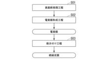
- FIG. 1 is a flow diagram showing a method for producing an insulating coating using an electrodeposition apparatus according to an embodiment of the present invention.
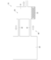
- 1 is a schematic explanatory diagram of an electrodeposition apparatus according to one embodiment of the present invention.
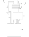
- FIG. 4 is a schematic explanatory diagram of an electrodeposition apparatus according to another embodiment of the present invention.
- the method for managing an electrodeposition liquid according to the present embodiment is for managing an electrodeposition liquid used when forming an electrodeposition film, which serves as a precursor of an insulating film, on the surface of a conductive substrate.
- the electrodeposition solution is controlled to be used in an anionic electrodeposition method in which a voltage is applied to a substrate as an anode to form an insulating film on the surface of the substrate, which serves as the anode.
- the electrodeposition solution to be managed contains water, an organic solvent, a solid component, and a neutralizing agent.
- the electrodeposition solution of the present embodiment is used in an anionic electrodeposition method, and therefore contains an amine as a neutralizing agent.
- the electrodeposition solution of the present embodiment may contain an appropriate amount of organic acid in advance. When the electrodeposition film contains an appropriate amount of organic acid, it is possible to suppress the occurrence of fine cracks in the baking step S03 described below.
- the organic acid may contain at least a carboxylic acid, such as formic acid, acetic acid, propionic acid, butyric acid, valeric acid, oxalic acid, malonic acid, benzoic acid, phthalic acid, trimellitic acid, and hydroxy acids.
- a carboxylic acid such as formic acid, acetic acid, propionic acid, butyric acid, valeric acid, oxalic acid, malonic acid, benzoic acid, phthalic acid, trimellitic acid, and hydroxy acids.
- hydroxy acids include glycolic acid, hydroxypropionic acid, hydroxybutyric acid, tartronic acid, and glyceric acid. Hydroxypropionic acid and hydroxybutyric acid are effective regardless of the position of the functional group, so that even positional isomers are effective.
- the solid component contains at least a polyimide resin, and preferably contains two types of resin, a polyimide resin and a fluorine-based resin.
- examples of the polyimide resin include polyamideimide, polyetherimide, polyimide, etc.
- examples of the fluorine resin include polytetrafluoroethylene, perfluoroalkoxyalkane, etc.
- the average particle size of the solid components may be 50 nm or more and 300 nm or less, more preferably 50 nm or more and 250 nm or less, and even more preferably 50 nm or more and 200 nm or less.
- the standard deviation of the particle size of the solid components may be 250 nm or less, more preferably 150 nm or less, and even more preferably 100 nm or less.
- the polyimide resin and the fluorine resin, which are solid components, are dispersed in the water and the organic solvent.
- the organic solvent include N,N-dimethylacetamide, propylene carbonate, dimethylsulfoxide, N,N-dimethylformamide, 4-butyrolactone, N-methyl-2-pyrrolidone, and N-methyl-2-pyrrolidone.
- the water content in the electrodeposition solution is preferably 15% by mass or more, more preferably 50% by mass or more, while the water content in the electrodeposition solution is preferably 85% by mass or less, more preferably 75% by mass or less. Furthermore, the content of the organic solvent in the electrodeposition solution is preferably 15% by mass or more, more preferably 50% by mass or more, while the content of the organic solvent in the electrodeposition solution is preferably 85% by mass or less, more preferably 75% by mass or less.
- the method for producing an insulating film in this embodiment includes a surface pretreatment step S01, an electrodeposition film formation step S02, and a baking step S03.
- a substrate on which an electrodeposited film (insulating film) is to be formed is prepared.
- This substrate is conductive and is made of a metal material such as copper or a copper alloy, aluminum or an aluminum alloy, etc.
- a surface treatment liquid such as an organic solvent or a surfactant.
- Electrodeposited film formation step S02 Next, the substrate and the counter electrode are immersed in the electrodeposition solution of this embodiment, and a voltage is applied between the anode (substrate) and the cathode (counter electrode) with the substrate as the anode and the counter electrode as the cathode.
- a voltage is applied between the anode (substrate) and the cathode (counter electrode) with the substrate as the anode and the counter electrode as the cathode.
- a solid component in this embodiment, a mixture of polyimide resin and fluororesin
- the organic acid since an organic acid is added to the electrodeposition solution, the organic acid has a pH buffering effect, and thus the organic acid is contained in the electrodeposition film.
- a solvent will be suitably included.
- the temperature of the electrodeposition liquid in the electrodeposition film forming step S02 is preferably adjusted to within a range of 5° C. or more and 35° C. or less.
- the liquid temperature is preferably adjusted to within a range of 5° C. or more and 35° C. or less.
- the voltage applied between the substrate (anode) and the counter electrode (cathode) in the electrodeposition film forming step S02 is preferably in the range of 10V or more and 600V or less.
- the applied voltage By setting the applied voltage to 10 V or more, the electrodeposition speed can be ensured and productivity can be improved.
- the applied voltage to 600 V or less by setting the applied voltage to 600 V or less, the generation of many bubbles on the surface of the substrate can be suppressed, and the generation of many irregularities in the insulating coating due to the bursting of the bubbles in the subsequent baking step S03 can be suppressed.
- baking process S03 the substrate on which the electrodeposition film containing the solid components obtained in the electrodeposition film formation step S02 has been formed is dried, for example, within a temperature range of 200° C. or higher and lower than the melting point of the solid components to remove the residual electrodeposition liquid, and then the electrodeposition film is baked onto the substrate to form an insulating coating.
- the baking temperature in the baking step S03 may be within a temperature range in which the electrodeposition film of the solid components is formed and an insulating film is formed on the substrate, for example, within a range of 200°C to 400°C.
- the baking time may be within a range of, for example, 0.5 minutes to 60 minutes.
- an insulating coating containing solid components is formed on the conductive substrate. If electrodeposition is continued, organic acids such as carboxylic acids are generated, and the concentration of the organic acids in the electrodeposition solution increases, which may cause blistering when the electrodeposition film is baked. Therefore, in this embodiment, the electrodeposition solution is managed so as to control the concentration of the organic acid in the electrodeposition solution.
- the electrodeposition apparatus 10 shown in FIG. 2 includes an electrodeposition tank 20 in which the electrodeposition liquid is stored and in which the substrate and the counter electrode are immersed, an anion exchange means 30 that performs an anion exchange treatment on the electrodeposition liquid, and an electrodeposition liquid circulation means 40 (an outlet pipe 41 and a return pipe 42) that circulates the electrodeposition liquid between the electrodeposition tank 20 and the anion exchange means 30.
- the electrodeposition tank 20 stores an electrodeposition liquid, into which the substrate, which acts as the anode, and the counter electrode, which acts as the cathode, are immersed. Then, a voltage is applied between the substrate and the counter electrode to form an electrodeposition film on the surface of the substrate.
- the anion exchange means 30 includes an anion exchange tank 31 in which an anion exchange resin 32 is disposed.
- the electrodeposition liquid is supplied from the electrodeposition tank 20 to the anion exchange tank 31 via an outlet pipe 41.
- organic acids contained in the electrodeposition liquid are removed by the anion exchange resin 32. This makes it possible to control the concentration of the organic acid contained in the electrodeposition solution.
- the organic acid contained in the electrodeposition solution can be carboxylic acid.
- the electrodeposition solution in which the concentration of the organic acid has been controlled in the anion exchange tank 31 is then supplied to the electrodeposition tank 20 via the return pipe 42 .
- the concentration of the organic acid is preferably controlled within the range of 5 mg/L to 500 mg/L.
- the method for managing the electrodeposition liquid which is the present embodiment configured as described above, controls the concentration of the organic acid contained in the electrodeposition liquid, so that even if electrodeposition is performed continuously, the concentration of the organic acid does not become excessively high, and the occurrence of blisters during baking can be suppressed, making it possible to stably form an insulating coating.
- the electrodeposition liquid contains water, an organic solvent, a solid component, and a neutralizing agent, and the solid component contains at least a polyimide-based resin
- an electrodeposition film containing at least a polyimide-based resin can be formed, and an insulating film with excellent insulating properties can be stably formed.
- the pH buffering effect of the organic acid can suppress a sudden drop in pH on the anode (substrate) surface, allowing a stable electrodeposition film to be formed.
- the pH buffering effect of the organic acid can suppress a sudden drop in pH on the anode (substrate) surface, allowing a stable electrodeposition film to be formed.
- the concentration of the organic acid in the electrodeposition solution is adjusted to within the range of 5 mg/L or more and 500 mg/L or less, a suitable pH buffer effect can be achieved, allowing the electrodeposition film to be formed stably and accurately suppressing the occurrence of blistering during baking.
- the electrodeposition liquid contains a fluororesin as well as a polyimide resin as solid components
- an electrodeposition film containing a mixed resin of a polyimide resin and a fluororesin can be formed, making it possible to stably form an insulating film with particularly excellent insulating properties.
- the electrodeposition device 10 of this embodiment includes an electrodeposition tank in which the electrodeposition liquid is stored and in which the substrate and counter electrode are immersed, an anion exchange means for performing an anion exchange process on the electrodeposition liquid, and an electrodeposition liquid circulation means for circulating the electrodeposition liquid between the electrodeposition tank and the anion exchange means.
- the present invention is not limited to this, and can be modified as appropriate without departing from the technical concept of the invention.
- the electrodeposition apparatus shown in FIG. 2 has been described as an example, but the present invention is not limited to this, and electrodeposition apparatuses of other configurations may also be used.
- the electrodeposition apparatus 110 shown in FIG. 3 may be used.
- the anion exchange means 130 for performing anion exchange processing on the electrodeposition solution may include an ultrafiltration device 131 and an exchange membrane tank 132 in which anion exchange membranes 133 and cation exchange membranes 134 are alternately arranged.
- a method using electrodialysis may be applied.
- the concentration of the organic acid contained in the electrodeposited film was evaluated as follows.
- the electrodeposition solution was diluted with ultrapure water, and then impurities were removed.
- the filtrate was passed through a membrane filter to prepare a solution for ion chromatography measurement.
- the measurements were performed using an ion chromatograph Thermo Fisher Scientific ICS-5000+.
- Anion exchange columns Dionex IonPac AG15 and Dionex IonPac AS15 were used as the stationary phase of the ion chromatograph, potassium hydroxide aqueous solution was used as the eluent, Dionex ADRS 600 was used as the suppressor, and electrical conductivity was used as the detector.
- the electrodeposition solutions of Inventive Examples 1 to 24, which were subjected to anion exchange treatment, and the electrodeposition solutions of Comparative Examples 1 to 3, which were not subjected to anion exchange treatment, were evaluated for stability.
- the electrodeposition solution was kept at 40° C. for 5 days, the solution in which precipitation or separation occurred was rated as “B”, and the solution in which no precipitation or separation occurred was rated as “A”.
- the evaluation results are shown in Tables 1 and 2.
- a rectangular bar of oxygen-free copper (1.47 mm ⁇ 2.94 mm ⁇ length 25 cm) was prepared as a conductive substrate, and a cylindrical copper plate was prepared as a counter electrode.
- the substrate and the counter electrode were immersed in the above-mentioned electrodeposition solution, and an electrodeposition film was formed by setting the temperature of the electrodeposition solution to 20° C., the applied voltage to 300 V, and the holding time to 0.5 minutes.
- the electrodeposited film was then baked using a three-stage heating profile in which the work temperature during baking was kept at 140-170°C for 10 minutes, at 240-260°C for 5 minutes, and at 340-350°C for 90 seconds, followed by rapid cooling, to form an insulating film.
- the appearance of the formed insulating film was then observed and evaluated for blistering.
- blistering was observed by visual inspection, the case where blistering was observed in the insulating coating was rated as "present", and when no blistering was observed, the case where blistering was observed was rated as "absent”.
- the dielectric constant of the insulating film was measured as follows. The evaluation results are shown in Tables 1 and 2. Silver paste was applied to the surface of the insulating film at two locations 10 mm from each end and at a central portion 100 mm from each end to prepare a measurement sample. The capacitance between the conductor and the silver paste at the central portion was measured using a Hioki E.E. Corporation LCR meter IM3536, and the dielectric constant was calculated from the measured capacitance and the thickness of the film.
- Examples 1 to 24 of the present invention the organic acid concentration in the electrodeposition solution was adjusted, and therefore the stability of the electrodeposition solution was evaluated as "A.” In addition, no blistering occurred in the insulating coating after baking. Furthermore, in Examples 18 and 19 of the present invention, polyimide resin and fluororesin were contained as solid components, and the relative dielectric constant was sufficiently low, and the insulating properties were particularly excellent.
- the present invention can provide a method for managing the electrodeposition liquid and an electrodeposition device that can prevent blistering when baking the electrodeposition film and can stably form an insulating film.
Landscapes
- Chemical & Material Sciences (AREA)
- Engineering & Computer Science (AREA)
- Organic Chemistry (AREA)
- Materials Engineering (AREA)
- Chemical Kinetics & Catalysis (AREA)
- Life Sciences & Earth Sciences (AREA)
- Electrochemistry (AREA)
- Metallurgy (AREA)
- Wood Science & Technology (AREA)
- Hydrology & Water Resources (AREA)
- Environmental & Geological Engineering (AREA)
- Water Supply & Treatment (AREA)
- General Chemical & Material Sciences (AREA)
- Health & Medical Sciences (AREA)
- Molecular Biology (AREA)
- Paints Or Removers (AREA)
- Electroplating Methods And Accessories (AREA)
- Application Of Or Painting With Fluid Materials (AREA)
Abstract
導電性の基材にアニオン電着によって電着膜を形成する際に用いられる電着液の管理方法であって、前記電着液に対してアニオン交換処理を行うことにより、前記電着液に含まれる有機酸の濃度を調整する。導電性の基材にアニオン電着によって電着膜を形成する際に用いられる電着装置(10)であって、電着液が貯留されるとともに、前記基材と対向電極が浸漬される電着槽(20)と、前記電着液に対してアニオン交換処理を行うアニオン交換手段(30)と、前記電着槽(20)と前記アニオン交換手段(30)との間で前記電着液を循環させる電着液循環手段(40)と、を備えている。
Description
本発明は、導電性の基材にアニオン電着によって電着膜を電着させる際に用いる電着液の管理方法、および、電着装置に関する。
本願は、2023年4月24日に日本に出願された特願2023-070848号及び2024年2月7日に日本に出願された特願2024-017168号に基づき優先権を主張し、その内容をここに援用する。
本願は、2023年4月24日に日本に出願された特願2023-070848号及び2024年2月7日に日本に出願された特願2024-017168号に基づき優先権を主張し、その内容をここに援用する。
導電性の基材を絶縁性の樹脂からなる絶縁皮膜で被覆した絶縁導体は、絶縁が必要な各種電気機器の導電材料や放熱板材料として広く用いられている。
絶縁皮膜の構成材料として、種々の樹脂が用いられており、例えば、特許文献1には、ポリアミドイミド樹脂等のポリイミド系樹脂を用いたものが開示されており、特許文献2には、ポリイミド系樹脂とフッ素系樹脂との混合樹脂を用いたものが提案されている。
絶縁皮膜の構成材料として、種々の樹脂が用いられており、例えば、特許文献1には、ポリアミドイミド樹脂等のポリイミド系樹脂を用いたものが開示されており、特許文献2には、ポリイミド系樹脂とフッ素系樹脂との混合樹脂を用いたものが提案されている。
このような絶縁性の樹脂からなる絶縁皮膜を導電性の基材の表面に形成する方法として、電着法が知られている。
電着法は、絶縁皮膜の材料を分散させた電着液に、絶縁皮膜を形成する基材と対向電極とを浸漬し、基材と対向電極との間に電圧を印加することによって、絶縁皮膜の材料を基材の表面に析出させた電着膜を形成する方法である。そして、形成した電着膜を加熱して、電着膜を基材に焼付けることによって絶縁皮膜が形成される。
電着法は、絶縁皮膜の材料を分散させた電着液に、絶縁皮膜を形成する基材と対向電極とを浸漬し、基材と対向電極との間に電圧を印加することによって、絶縁皮膜の材料を基材の表面に析出させた電着膜を形成する方法である。そして、形成した電着膜を加熱して、電着膜を基材に焼付けることによって絶縁皮膜が形成される。
また、電着法においては、基材を陽極として電圧を印加し、基材の表面に絶縁皮膜を形成するアニオン電着法と、基材を陰極として電圧を印加し、基材の表面に絶縁皮膜を形成するカチオン電着法とがある。
ところで、アニオン電着法に用いられるアニオン電着液においては、上述の樹脂を含む固形成分と、水と、有機溶媒と、中和剤とを含んでおり、電圧の印加によって、陽極(基材)の表面近傍でpHが低下し、固形成分が陽極(基材)の表面に析出し、電着膜が形成される。
ここで、アニオン電着法にて電着を継続して実施していると、陽極の表面に形成された電着膜を焼き付けて絶縁皮膜を形成した際に、膨れが生じるおそれがあった。
ここで、アニオン電着法にて電着を継続して実施していると、陽極の表面に形成された電着膜を焼き付けて絶縁皮膜を形成した際に、膨れが生じるおそれがあった。
本発明は、以上の状況に鑑みてなされたものであって、電着膜を焼き付ける際に膨れが発生することを抑制でき、絶縁皮膜を安定して形成可能な電着液の管理方法、および、電着装置を提供することを目的とする。
上記課題を解決するために、本発明者らが鋭意検討した結果、アニオン電着法で電着を継続して実施すると、電着液に含まれる有機酸の濃度が増加し、電着膜を焼き付けた際に膨れが生じることが分かった。
よって、電着液に含まれる有機酸の濃度を適切に制御することにより、焼き付け時における膨れの発生を抑制可能となるとの知見を得た。
よって、電着液に含まれる有機酸の濃度を適切に制御することにより、焼き付け時における膨れの発生を抑制可能となるとの知見を得た。
本発明は上述の知見に基づいてなされたものであって、本発明の態様1の電着液の管理方法は、導電性の基材にアニオン電着によって電着膜を形成する際に用いられる電着液の管理方法であって、前記電着液に対してアニオン交換処理を行うことにより、前記電着液に含まれる有機酸の濃度を調整することを特徴としている。
本発明の態様1の電着液の管理方法によれば、電着液に含まれる有機酸の濃度を制御しているので、電着を継続して実施した場合であっても、有機酸の濃度が過剰に高くならず、焼き付け時における膨れの発生を抑制することができ、絶縁皮膜を安定して形成することが可能となる。
本発明の態様2の電着液の管理方法は、本発明の態様1の電着液の管理方法において、前記電着液が、水と、有機溶媒と、固形成分と、中和剤と、を含み、前記固形成分は、少なくともポリイミド系樹脂を含むことを特徴としている。
本発明の態様2の電着液の管理方法によれば、前記固形成分として、少なくともポリイミド系樹脂を含んでいるので、絶縁特性に優れた絶縁皮膜を安定して形成することが可能となる。
本発明の態様2の電着液の管理方法によれば、前記固形成分として、少なくともポリイミド系樹脂を含んでいるので、絶縁特性に優れた絶縁皮膜を安定して形成することが可能となる。
本発明の態様3の電着液の管理方法は、本発明の態様1または態様2の電着液の管理方法において、前記電着液が、前記有機酸として少なくともカルボン酸を含有することを特徴としている。
本発明の態様3の電着液の管理方法によれば、前記電着液が、前記有機酸として少なくともカルボン酸を含有しているので、有機酸であるカルボン酸のpH緩衝効果によって、陽極(基材)表面におけるpHの急激な低下を抑制でき、安定して電着膜を成膜することができる。
本発明の態様3の電着液の管理方法によれば、前記電着液が、前記有機酸として少なくともカルボン酸を含有しているので、有機酸であるカルボン酸のpH緩衝効果によって、陽極(基材)表面におけるpHの急激な低下を抑制でき、安定して電着膜を成膜することができる。
本発明の態様4の電着液の管理方法は、本発明の態様1または態様2の電着液の管理方法において、前記電着液が、前記有機酸として少なくともヒドロキシ酸を含有することを特徴としている。
本発明の態様4の電着液の管理方法によれば、前記電着液が、前記有機酸として少なくともヒドロキシ酸を含有しているので、有機酸であるヒドロキシ酸のpH緩衝効果によって、陽極(基材)表面におけるpHの急激な低下を抑制でき、安定して電着膜を成膜することができる。
本発明の態様4の電着液の管理方法によれば、前記電着液が、前記有機酸として少なくともヒドロキシ酸を含有しているので、有機酸であるヒドロキシ酸のpH緩衝効果によって、陽極(基材)表面におけるpHの急激な低下を抑制でき、安定して電着膜を成膜することができる。
本発明の態様5の電着液の管理方法は、本発明の態様1から態様4のいずれかひとつの電着液の管理方法において、前記電着液における前記有機酸の濃度を5mg/L以上500mg/L以下の範囲内に調整することを特徴としている。
本発明の態様5の電着液によれば、前記有機酸の濃度を5mg/L以上500mg/L以下の範囲内に調整しているので、適度なpH緩衝効果を作用させることができ、安定して電着膜を成膜することができるとともに、焼き付け時の膨れの発生を的確に抑制することができる。
本発明の態様5の電着液によれば、前記有機酸の濃度を5mg/L以上500mg/L以下の範囲内に調整しているので、適度なpH緩衝効果を作用させることができ、安定して電着膜を成膜することができるとともに、焼き付け時の膨れの発生を的確に抑制することができる。
本発明の態様6の電着液の管理方法は、本発明の態様1から態様5のいずれかひとつの電着液において、前記固形成分は、ポリイミド系樹脂とともにフッ素樹脂を含むことを特徴としている。
本発明の態様6の電着液の管理方法によれば、前記固形成分として、ポリイミド系樹脂とともにフッ素樹脂を含有しているので、絶縁特性と誘電特性に特に優れた絶縁皮膜を成膜することが可能となる。
本発明の態様6の電着液の管理方法によれば、前記固形成分として、ポリイミド系樹脂とともにフッ素樹脂を含有しているので、絶縁特性と誘電特性に特に優れた絶縁皮膜を成膜することが可能となる。
本発明の態様7の電着装置は、導電性の基材にアニオン電着によって電着膜を形成する際に用いられる電着装置であって、電着液が貯留されるとともに、前記基材と対向電極が浸漬される電着槽と、前記電着液に対してアニオン交換処理を行うアニオン交換手段と、前記電着槽と前記アニオン交換手段との間で前記電着液を循環させる電着液循環手段と、を備えていることを特徴としている。
本発明の態様7の電着装置によれば、電着槽と、前記電着液に対してアニオン交換処理を行うアニオン交換手段と、前記電着槽と前記アニオン交換手段との間で前記電着液を循環させる電着液循環手段と、を備えているので、電着液に含まれる有機酸の濃度を適切に制御することができ、電着を継続して実施した場合であっても、有機酸の濃度が過剰に高くならず、焼き付け時における膨れの発生を抑制することができ、絶縁皮膜を安定して形成することが可能となる。
本発明によれば、電着膜を焼き付ける際に膨れが発生することを抑制でき、絶縁皮膜を安定して形成可能な電着液の管理方法、および、電着装置を提供することができる。
以下に、本発明の一実施形態である電着液の管理方法、および、電着装置について説明する。
本実施形態である電着液の管理方法は、導電性の基材の表面に絶縁皮膜の前駆体となる電着膜を成膜する際に使用される電着液を管理するものである。
なお、本実施形態においては、基材を陽極として電圧を印加し、陽極である基材の表面に絶縁皮膜を形成するアニオン電着法に用いられる電着液を管理するものである。
本実施形態である電着液の管理方法は、導電性の基材の表面に絶縁皮膜の前駆体となる電着膜を成膜する際に使用される電着液を管理するものである。
なお、本実施形態においては、基材を陽極として電圧を印加し、陽極である基材の表面に絶縁皮膜を形成するアニオン電着法に用いられる電着液を管理するものである。
本実施形態において、管理対象となる電着液においては、水と、有機溶媒と、固形成分と、中和剤と、を含んでいる。
なお、本実施形態の電着液においては、上述のように、アニオン電着法に用いられるものであることから、中和剤としてアミンを含んでいる。
また、本実施形態の電着液においては、予め適量の有機酸を含んでいてもよい。電着膜が適量の有機酸を含むことで、後述する焼き付け工程S03において、微細なクラックが発生することを抑制することが可能となる。
なお、本実施形態の電着液においては、上述のように、アニオン電着法に用いられるものであることから、中和剤としてアミンを含んでいる。
また、本実施形態の電着液においては、予め適量の有機酸を含んでいてもよい。電着膜が適量の有機酸を含むことで、後述する焼き付け工程S03において、微細なクラックが発生することを抑制することが可能となる。
有機酸として、少なくともカルボン酸を含有していてもよい。カルボン酸としては、例えば、ギ酸、酢酸、プロピオン酸、酪酸、吉草酸、シュウ酸、マロン酸、安息香酸、フタル酸、トリメリット酸、ヒドロキシ酸等が挙げられる。
特に、有機酸として、少なくともカルボン酸を含有していることが好ましい。ヒドロキシ酸としては、例えば、グリコール酸、ヒドロキシプロピオン酸、ヒドロキシ酪酸、タルトロン酸、グリセリン酸等が挙げられる。なお、ヒドロキシプロピオン酸やヒドロキシ酪酸などは官能基の位置によらず効果を発揮するため位置異性体であっても効果を生じる。
特に、有機酸として、少なくともカルボン酸を含有していることが好ましい。ヒドロキシ酸としては、例えば、グリコール酸、ヒドロキシプロピオン酸、ヒドロキシ酪酸、タルトロン酸、グリセリン酸等が挙げられる。なお、ヒドロキシプロピオン酸やヒドロキシ酪酸などは官能基の位置によらず効果を発揮するため位置異性体であっても効果を生じる。
本実施形態においては、固形成分は、少なくともポリイミド系樹脂を含むものとされており、ポリイミド系樹脂およびフッ素系樹脂の2種類の樹脂を含むものであることが好ましい。
ここで、本実施形態においては、ポリイミド系樹脂としては、ポリアミドイミド、ポリエーテルイミド、ポリイミド等が挙げられる。また、フッ素系樹脂としては、ポリテトラフルオロエチレン、ペルフルオロアルコキシアルカン等が挙げられる。
ここで、本実施形態においては、ポリイミド系樹脂としては、ポリアミドイミド、ポリエーテルイミド、ポリイミド等が挙げられる。また、フッ素系樹脂としては、ポリテトラフルオロエチレン、ペルフルオロアルコキシアルカン等が挙げられる。
また、固形成分の平均粒径は、50nm以上300nm以下、より好ましくは50nm以上250nm以下、さらに好ましくは50nm以上200nm以下であればよい。また、固形成分の粒径の標準偏差は250nm以下、より好ましくは150nm以下、さらに好ましくは100nm以下であればよい。
水および有機溶媒は、固形成分であるポリイミド系樹脂およびフッ素系樹脂が分散されるものである。
ここで、有機溶媒としては、例えば、N,N-ジメチルアセトアミド、プロピレンカーボネイト、ジメチルスルホキシド、N,N-ジメチルホルムアミド、4-ブチロラクトン、N-メチル-2-ピロリドン、N-メチル-2-ピロリドン等が挙げられる。
ここで、有機溶媒としては、例えば、N,N-ジメチルアセトアミド、プロピレンカーボネイト、ジメチルスルホキシド、N,N-ジメチルホルムアミド、4-ブチロラクトン、N-メチル-2-ピロリドン、N-メチル-2-ピロリドン等が挙げられる。
また、電着液中の水の含有割合は、15質量%以上であることが好ましく、50質量%以上であることがさらに好ましい。一方、電着液中の水の含有割合は、85質量%以下であることが好ましく、75質量%以下であることがさらに好ましい。
さらに、電着液中の有機溶剤の含有割合は、15質量%以上であることが好ましく、50質量%以上であることがさらに好ましい。一方、電着液中の有機溶剤の含有割合は、85質量%以下であることが好ましく、75質量%以下であることがさらに好ましい。
さらに、電着液中の有機溶剤の含有割合は、15質量%以上であることが好ましく、50質量%以上であることがさらに好ましい。一方、電着液中の有機溶剤の含有割合は、85質量%以下であることが好ましく、75質量%以下であることがさらに好ましい。
次に、電着液を用いた絶縁皮膜の製造方法について、図1を参照して説明する。
図1に示すように、本実施形態における絶縁皮膜の製造方法は、表面前処理工程S01と、電着膜形成工程S02と、焼き付け工程S03とを有している。
図1に示すように、本実施形態における絶縁皮膜の製造方法は、表面前処理工程S01と、電着膜形成工程S02と、焼き付け工程S03とを有している。
(表面前処理工程S01)
まず、電着膜(絶縁皮膜)を形成する基材を準備する。この基材は、導電性を有しており、例えば、銅又は銅合金、アルミニウム又はアルミニウム合金等の金属材料で構成されている。
そして、有機溶剤や界面活性剤等の表面処理液を用いて、上述の基材の表面を付着している油脂や酸化皮膜を取り除く。
まず、電着膜(絶縁皮膜)を形成する基材を準備する。この基材は、導電性を有しており、例えば、銅又は銅合金、アルミニウム又はアルミニウム合金等の金属材料で構成されている。
そして、有機溶剤や界面活性剤等の表面処理液を用いて、上述の基材の表面を付着している油脂や酸化皮膜を取り除く。
(電着膜形成工程S02)
次に、本実施形態である電着液に、基材と対向電極とを浸漬し、基材を陽極、対向電極を陰極として、陽極(基材)と陰極(対向電極)との間に電圧を印加する。これにより、基材の周辺の電着液のpHが低下し、基材の表面に固形成分(本実施形態では、ポリイミド系樹脂とフッ素系樹脂との混合物)が析出する。これにより、基材の表面に電着膜を形成する。このとき、本実施形態においては、電着液に有機酸が添加されているので、有機酸のpH緩衝効果により電着膜の中に有機溶媒が適切に含有されることになる。
次に、本実施形態である電着液に、基材と対向電極とを浸漬し、基材を陽極、対向電極を陰極として、陽極(基材)と陰極(対向電極)との間に電圧を印加する。これにより、基材の周辺の電着液のpHが低下し、基材の表面に固形成分(本実施形態では、ポリイミド系樹脂とフッ素系樹脂との混合物)が析出する。これにより、基材の表面に電着膜を形成する。このとき、本実施形態においては、電着液に有機酸が添加されているので、有機酸のpH緩衝効果により電着膜の中に有機溶媒が適切に含有されることになる。
電着膜形成工程S02における電着液の温度(液温)は、5℃以上35℃以下の範囲内に調整することが好ましい。
液温を5℃以上とすることで、結露によって電着液に水が混入することを抑制できる。一方、液温を35℃以下とすることで、電着液の保存安定性が向上し、安定して電着膜を成膜することができる。
液温を5℃以上とすることで、結露によって電着液に水が混入することを抑制できる。一方、液温を35℃以下とすることで、電着液の保存安定性が向上し、安定して電着膜を成膜することができる。
電着膜形成工程S02における基材(陽極)と対向電極(陰極)との間の印加電圧は、10V以上600V以下の範囲内とすることが好ましい。
印加電圧を10V以上とすることで、電着速度を確保でき、生産性を向上させることができる。一方、印加電圧を600V以下とすることで、基材の表面に気泡が多く発生することを抑制でき、後工程の焼き付け工程S03において、気泡が弾けて、絶縁皮膜に多数の凹凸が生じることを抑制できる。
印加電圧を10V以上とすることで、電着速度を確保でき、生産性を向上させることができる。一方、印加電圧を600V以下とすることで、基材の表面に気泡が多く発生することを抑制でき、後工程の焼き付け工程S03において、気泡が弾けて、絶縁皮膜に多数の凹凸が生じることを抑制できる。
(焼き付け工程S03)
焼き付け工程S03では、電着膜形成工程S02で得られた固形成分を含む電着膜が形成された基材を、例えば、200℃以上、かつ固形成分の融点以下の温度範囲内で乾燥させて残留電着液を除去した後、電着膜を基材に焼き付けて絶縁皮膜を形成する。
焼き付け工程S03では、電着膜形成工程S02で得られた固形成分を含む電着膜が形成された基材を、例えば、200℃以上、かつ固形成分の融点以下の温度範囲内で乾燥させて残留電着液を除去した後、電着膜を基材に焼き付けて絶縁皮膜を形成する。
焼き付け工程S03における焼き付け温度は、固形成分の電着膜が造膜して、基材に絶縁皮膜が形成される温度範囲であればよく、例えば、200℃以上400℃以下の範囲内にすればよい。また、焼き付け時間は、例えば、0.5分間以上60分間以下の範囲内であればよい。
以上のような工程を経て、導電性の基材に、固形成分を含む絶縁皮膜が形成されることになる。
ここで、電着を継続して実施していると、カルボン酸等の有機酸が生成し、電着液に含まれる有機酸の濃度が高くなる。すると、電着膜を焼き付ける際に、膨れが生じるおそれがある。
そこで、本実施形態においては、電着液中の有機酸の濃度を制御するように、電着液の管理を行う。
ここで、電着を継続して実施していると、カルボン酸等の有機酸が生成し、電着液に含まれる有機酸の濃度が高くなる。すると、電着膜を焼き付ける際に、膨れが生じるおそれがある。
そこで、本実施形態においては、電着液中の有機酸の濃度を制御するように、電着液の管理を行う。
ここで、本実施形態である電着装置10、および、この電着装置30を用いた電着液の管理方法について、図2を参照して説明する。
図2に示す電着装置10は、電着液が貯留されるとともに基材と対向電極が浸漬される電着槽20と、電着液に対してアニオン交換処理を行うアニオン交換手段30と、電着槽20とアニオン交換手段30との間で電着液を循環させる電着液循環手段40(取出配管41および戻し配管42)と、を備えている。
図2に示す電着装置10は、電着液が貯留されるとともに基材と対向電極が浸漬される電着槽20と、電着液に対してアニオン交換処理を行うアニオン交換手段30と、電着槽20とアニオン交換手段30との間で電着液を循環させる電着液循環手段40(取出配管41および戻し配管42)と、を備えている。
電着槽20には、電着液が貯留されており、この電着液に、陽極となる基材と陰極となる対向電極とが、浸漬される。そして、これら基材と対向電極との間に電圧を負荷することで基材の表面に電着膜を形成する。
アニオン交換手段30は、図2に示すように、アニオン交換樹脂32が配置されたアニオン交換槽31を備えている。
電着槽20から取出配管41を介してアニオン交換槽31に電着液が供給される。電着液がアニオン交換槽31に貯留されることにより、アニオン交換樹脂32によって、電着液に含まれる有機酸が除去される。
これにより、電着液に含まれる有機酸の濃度を制御することが可能となる。なお、電着液に含まれる有機酸としては、カルボン酸が挙げられる。
電着槽20から取出配管41を介してアニオン交換槽31に電着液が供給される。電着液がアニオン交換槽31に貯留されることにより、アニオン交換樹脂32によって、電着液に含まれる有機酸が除去される。
これにより、電着液に含まれる有機酸の濃度を制御することが可能となる。なお、電着液に含まれる有機酸としては、カルボン酸が挙げられる。
そして、このアニオン交換槽31において有機酸の濃度が制御された電着液が戻し配管42を介して電着槽20への供給されることになる。
ここで、電着槽20に貯留される電着液においては、有機酸の濃度は5mg/L以上500mg/L以下の範囲内に制御することが好ましい。
ここで、電着槽20に貯留される電着液においては、有機酸の濃度は5mg/L以上500mg/L以下の範囲内に制御することが好ましい。
以上のような構成とされた本実施形態である電着液の管理方法によれば、電着液に含まれる有機酸の濃度を制御しているので、電着を継続して実施した場合であっても、有機酸の濃度が過剰に高くならず、焼き付け時における膨れの発生を抑制することができ、絶縁皮膜を安定して形成することが可能となる。
本実施形態において、電着液が、水と、有機溶媒と、固形成分と、中和剤と、を含み、前記固形成分は、少なくともポリイミド系樹脂を含む場合には、少なくともポリイミド系樹脂を含む電着膜を成膜することができ、絶縁特性に優れた絶縁皮膜を安定して形成することが可能となる。
本実施形態において、電着液が有機酸として少なくともカルボン酸を含有する場合には、有機酸のpH緩衝効果によって、陽極(基材)表面におけるpHの急激な低下を抑制でき、安定して電着膜を成膜することができる。
本実施形態において、電着液が有機酸として少なくともヒドロキシ酸を含有する場合には、有機酸のpH緩衝効果によって、陽極(基材)表面におけるpHの急激な低下を抑制でき、安定して電着膜を成膜することができる。
本実施形態において、電着液における有機酸の濃度を5mg/L以上500mg/L以下の範囲内に調整する場合には、適度なpH緩衝効果を作用させることができ、安定して電着膜を成膜することができるとともに、焼き付け時の膨れの発生を的確に抑制することができる。
本実施形態において、電着液が、固形成分としてポリイミド系樹脂とともにフッ素樹脂を含む場合には、ポリイミド系樹脂とフッ素樹脂との混合樹脂を含む電着膜を成膜することができ、絶縁特性に特に優れた絶縁皮膜を安定して形成することが可能となる。
本実施形態である電着装置10によれば、電着液が貯留されるとともに、前記基材と対向電極が浸漬される電着槽と、前記電着液に対してアニオン交換処理を行うアニオン交換手段と、前記電着槽と前記アニオン交換手段との間で前記電着液を循環させる電着液循環手段と、を備えているので、電着液に含まれる有機酸の濃度を適切に調整することができ、電着を継続して実施した場合であっても、有機酸の濃度が過剰に高くならず、焼き付け時における膨れの発生を抑制することができ、絶縁皮膜を安定して形成することが可能となる。
以上、本発明の実施形態について説明したが、本発明はこれに限定されることはなく、その発明の技術的思想を逸脱しない範囲で適宜変更可能である。
本実施形態においては、図2に示す電着装置を例に挙げて説明したが、これに限定されることはなく、他の構成の電着装置であってもよい。
本実施形態においては、図2に示す電着装置を例に挙げて説明したが、これに限定されることはなく、他の構成の電着装置であってもよい。
例えば、図3に示す電着装置110であってもよい。図3に示す電着装置110においては、電着液に対してアニオン交換処理を行うアニオン交換手段130が、限外ろ過装置131と、アニオン交換膜133とカチオン交換膜134とが交互に配設された交換膜槽132と、を備えたものであってもよい。その他の、有機酸を制御する方法として、電気透析を用いた方法などを適用してもよい。
以下に、本発明の有効性を確認するために行った確認実験の結果について説明する。
表1,2に示すように、水、有機溶媒、固形成分、中和剤、有機酸を準備し、これらを表1,2に示す(質量比)となるように混合して電着液を得た。
本発明例1~24においては、図2に示す電着装置を用いて、電着液に対してアニオン交換処理を行った。その結果、有機酸の濃度の変化について表1,2に示す。
本発明例1~24においては、図2に示す電着装置を用いて、電着液に対してアニオン交換処理を行った。その結果、有機酸の濃度の変化について表1,2に示す。
ここで、電着膜に含まれる有機酸の濃度は、以下のようにして評価した。
電着液を超純水で希釈した後、夾雑物を除去およびメンブランフィルターに通した濾液をイオンクロマトグラフィー測定用の溶液とした。
次に、イオンクロマトグラフThermo Fisher Scientific ICS-5000+を用いて測定した。イオンクロマトグラフの固定相として陰イオン交換カラムDionex IonPac AG15およびDionex IonPac AS15、溶離液として水酸化カリウム水溶液、サプレッサーとしてDionex ADRS 600、検出器として電気伝導度を使用した。
電着液を超純水で希釈した後、夾雑物を除去およびメンブランフィルターに通した濾液をイオンクロマトグラフィー測定用の溶液とした。
次に、イオンクロマトグラフThermo Fisher Scientific ICS-5000+を用いて測定した。イオンクロマトグラフの固定相として陰イオン交換カラムDionex IonPac AG15およびDionex IonPac AS15、溶離液として水酸化カリウム水溶液、サプレッサーとしてDionex ADRS 600、検出器として電気伝導度を使用した。
また、アニオン交換処理を行った本発明例1~24の電着液、および、アニオン交換処理を行っていない比較例1~3の電着液の安定性について評価した。
電着液を40℃で5日間保持した際に、電着液に沈殿や分離が生じたものを「B」、電着液に沈殿や分離が生じなかったものを「A」と評価した。評価結果を表1,2に示す。
電着液を40℃で5日間保持した際に、電着液に沈殿や分離が生じたものを「B」、電着液に沈殿や分離が生じなかったものを「A」と評価した。評価結果を表1,2に示す。
そして、導電性の基材として無酸素銅の平角棒材(1.47mm×2.94mm×長さ25cm)を準備するとともに、対向電極として円筒状の銅板を準備した。
上述の電着液に基材と対向電極を浸漬し、電着液の液温を20℃、印加電圧を300V、保持時間0.5分として、電着膜を形成した。
その後、電着膜に対して、焼き付け時のワーク温度140~170℃にて10分間、240~260℃にて5分間、340~350℃にて90秒保持後、速やかに冷却する三段階の昇温プロファイルで焼き付けを行い、絶縁皮膜を形成した。
上述の電着液に基材と対向電極を浸漬し、電着液の液温を20℃、印加電圧を300V、保持時間0.5分として、電着膜を形成した。
その後、電着膜に対して、焼き付け時のワーク温度140~170℃にて10分間、240~260℃にて5分間、340~350℃にて90秒保持後、速やかに冷却する三段階の昇温プロファイルで焼き付けを行い、絶縁皮膜を形成した。
そして、形成した絶縁皮膜の外観を観察し、膨れについて評価した。
目視観察で、絶縁皮膜に膨れが認められた場合を「あり」、認められなかった場合を「なし」と評価した。
さらに、絶縁皮膜の比誘電率を以下のように測定した。評価結果を表1,2に示す。 絶縁皮膜表面の端2箇所10mmと中央部分100mmに銀ペーストを塗布し、測定用サンプルを作製する。導体と中央部分の銀ペースト間の静電容量を日置電機製LCRメータIM3536で測定し、測定した静電容量と皮膜の厚みから比誘電率を算出した。
目視観察で、絶縁皮膜に膨れが認められた場合を「あり」、認められなかった場合を「なし」と評価した。
さらに、絶縁皮膜の比誘電率を以下のように測定した。評価結果を表1,2に示す。 絶縁皮膜表面の端2箇所10mmと中央部分100mmに銀ペーストを塗布し、測定用サンプルを作製する。導体と中央部分の銀ペースト間の静電容量を日置電機製LCRメータIM3536で測定し、測定した静電容量と皮膜の厚みから比誘電率を算出した。


比較例1~3においては、電着液に含まれる有機酸濃度の調整を行っていないことから、電着液の安定性の評価が「B」となった。また、焼き付け後の絶縁皮膜には、膨れが発生した。
これに対して、本発明例1~24においては、電着液に含まれる有機酸濃度の調整を行っていることから、電着液の安定性の評価が「A」となった。また、焼き付け後の絶縁皮膜には、膨れが発生しなかった。
さらに、本発明例18,19においては、固形成分として、ポリイミド系樹脂とフッ素樹脂を含んでおり、比誘電率が十分に低くなり、絶縁特性に特に優れていた。
さらに、本発明例18,19においては、固形成分として、ポリイミド系樹脂とフッ素樹脂を含んでおり、比誘電率が十分に低くなり、絶縁特性に特に優れていた。
以上の確認実験の結果から、本発明例によれば、電着膜を焼き付ける際に膨れが発生することを抑制でき、絶縁皮膜を安定して形成可能な電着液の管理方法、および、電着装置を提供可能であることが確認された。
電着膜を焼き付ける際に膨れが発生することを抑制でき、絶縁皮膜を安定して形成可能な電着液の管理方法、および、電着装置を提供することができる。
Claims (7)
- 導電性の基材にアニオン電着によって電着膜を形成する際に用いられる電着液の管理方法であって、
前記電着液に対してアニオン交換処理を行うことにより、前記電着液に含まれる有機酸の濃度を調整することを特徴とする電着液の管理方法。 - 前記電着液が、水と、有機溶媒と、固形成分と、中和剤と、を含み、前記固形成分は、少なくともポリイミド系樹脂を含むことを特徴とする請求項1に記載の電着液の管理方法。
- 前記電着液が、前記有機酸として少なくともカルボン酸を含有することを特徴とする請求項1に記載の電着液の管理方法。
- 前記電着液が、前記有機酸として少なくともヒドロキシ酸を含有することを特徴とする請求項1に記載の電着液の管理方法。
- 前記電着液における前記有機酸の濃度を5mg/L以上500mg/L以下の範囲内に調整することを特徴とする請求項1に記載の電着液の管理方法。
- 前記電着液は、固形成分として、ポリイミド系樹脂とともにフッ素樹脂を含むことを特徴とする請求項1に記載の電着液の管理方法。
- 導電性の基材にアニオン電着によって電着膜を形成する際に用いられる電着装置であって、
電着液が貯留されるとともに、前記基材と対向電極が浸漬される電着槽と、前記電着液に対してアニオン交換処理を行うアニオン交換手段と、前記電着槽と前記アニオン交換手段との間で前記電着液を循環させる電着液循環手段と、を備えていることを特徴とする電着装置。
Priority Applications (2)
| Application Number | Priority Date | Filing Date | Title |
|---|---|---|---|
| DE112024002046.1T DE112024002046T5 (de) | 2023-04-24 | 2024-04-03 | Verfahren zur handhabung einer flüssigkeit für die elektrolytische abscheidung, und vorrichtung für die elektrolytische abscheidung |
| CN202480027159.4A CN121002229A (zh) | 2023-04-24 | 2024-04-03 | 电沉积液的管理方法及电沉积装置 |
Applications Claiming Priority (4)
| Application Number | Priority Date | Filing Date | Title |
|---|---|---|---|
| JP2023070848 | 2023-04-24 | ||
| JP2023-070848 | 2023-04-24 | ||
| JP2024017168A JP2024156602A (ja) | 2023-04-24 | 2024-02-07 | 電着液の管理方法、および、電着装置 |
| JP2024-017168 | 2024-02-07 |
Publications (1)
| Publication Number | Publication Date |
|---|---|
| WO2024224969A1 true WO2024224969A1 (ja) | 2024-10-31 |
Family
ID=93256321
Family Applications (1)
| Application Number | Title | Priority Date | Filing Date |
|---|---|---|---|
| PCT/JP2024/013841 Ceased WO2024224969A1 (ja) | 2023-04-24 | 2024-04-03 | 電着液の管理方法、および、電着装置 |
Country Status (4)
| Country | Link |
|---|---|
| CN (1) | CN121002229A (ja) |
| DE (1) | DE112024002046T5 (ja) |
| TW (1) | TW202503123A (ja) |
| WO (1) | WO2024224969A1 (ja) |
Citations (5)
| Publication number | Priority date | Publication date | Assignee | Title |
|---|---|---|---|---|
| JPS5310639A (en) * | 1976-07-16 | 1978-01-31 | Nippon Paint Co Ltd | Method of anionic electrodeposition |
| JPS59229496A (ja) * | 1983-05-14 | 1984-12-22 | Honda Motor Co Ltd | 鋼材の塗装前処理剤及び塗装前処理方法 |
| JPH05327183A (ja) * | 1992-05-26 | 1993-12-10 | Toagosei Chem Ind Co Ltd | 電着浴の管理方法 |
| WO2018151091A1 (ja) * | 2017-02-16 | 2018-08-23 | 三菱マテリアル株式会社 | 電着液及びこれを用いた絶縁皮膜付き導体の製造方法 |
| JP2022096090A (ja) * | 2020-12-17 | 2022-06-29 | トリニティ工業株式会社 | 電着塗装方法、電着塗装設備 |
-
2024
- 2024-04-03 DE DE112024002046.1T patent/DE112024002046T5/de active Pending
- 2024-04-03 WO PCT/JP2024/013841 patent/WO2024224969A1/ja not_active Ceased
- 2024-04-03 CN CN202480027159.4A patent/CN121002229A/zh active Pending
- 2024-04-11 TW TW113113597A patent/TW202503123A/zh unknown
Patent Citations (5)
| Publication number | Priority date | Publication date | Assignee | Title |
|---|---|---|---|---|
| JPS5310639A (en) * | 1976-07-16 | 1978-01-31 | Nippon Paint Co Ltd | Method of anionic electrodeposition |
| JPS59229496A (ja) * | 1983-05-14 | 1984-12-22 | Honda Motor Co Ltd | 鋼材の塗装前処理剤及び塗装前処理方法 |
| JPH05327183A (ja) * | 1992-05-26 | 1993-12-10 | Toagosei Chem Ind Co Ltd | 電着浴の管理方法 |
| WO2018151091A1 (ja) * | 2017-02-16 | 2018-08-23 | 三菱マテリアル株式会社 | 電着液及びこれを用いた絶縁皮膜付き導体の製造方法 |
| JP2022096090A (ja) * | 2020-12-17 | 2022-06-29 | トリニティ工業株式会社 | 電着塗装方法、電着塗装設備 |
Also Published As
| Publication number | Publication date |
|---|---|
| CN121002229A (zh) | 2025-11-21 |
| DE112024002046T5 (de) | 2026-02-19 |
| TW202503123A (zh) | 2025-01-16 |
Similar Documents
| Publication | Publication Date | Title |
|---|---|---|
| WO2018008745A1 (ja) | エッチング液組成物およびエッチング方法 | |
| CN109478572B (zh) | 用于从毛细管悬浮液生产高导电性可印刷浆料的工艺 | |
| US9396834B2 (en) | Metal foil provided with filler-containing resin layer and method for manufacturing metal foil provided with filler-containing resin layer | |
| WO2024224969A1 (ja) | 電着液の管理方法、および、電着装置 | |
| JP2024156602A (ja) | 電着液の管理方法、および、電着装置 | |
| Eftekhari | Improving Cu metallization of Si by electrodeposition under centrifugal fields | |
| US6540900B1 (en) | Method of anodizing aluminum capacitor foil for use in low voltage, surface mount capacitors | |
| TW201928997A (zh) | 絕緣導體及絕緣導體之製造方法 | |
| WO2024224964A1 (ja) | 電着液、絶縁皮膜の製造方法 | |
| JP2024156601A (ja) | 電着液、絶縁皮膜の製造方法 | |
| JP7375777B2 (ja) | 電着液、絶縁皮膜の製造方法 | |
| US10961399B2 (en) | Method of manufacturing of insulated flat long-length second generation high-temperature superconducting wires and wire | |
| JP4334663B2 (ja) | 重合皮膜の形成方法と、これを用いた金属材料の絶縁被覆方法および絶縁被覆金属導体 | |
| Wang et al. | Study of the Effect of Bias Voltage on the Electrochemical Migration Failure of Surface-Mount Resistor | |
| WO2018159279A1 (ja) | 絶縁電線及びその製造方法並びにコイル | |
| TWI586847B (zh) | 電鍍裝置 | |
| Chen et al. | Investigation of electrochemical migration on fine pitch BGA package | |
| JP2008050674A (ja) | 酸化物皮膜形成方法および酸化物皮膜形成装置 | |
| JP2017137541A (ja) | 電着液及びこれを用いた絶縁皮膜の形成方法 | |
| US20240309537A1 (en) | Nanodiamond article and associated methods of fabrication | |
| RU2526988C2 (ru) | Способ нанесения электроизоляционного покрытия на металлическую основу | |
| TWI796607B (zh) | 銅銠鍍層的製備方法 | |
| WO2016129518A1 (ja) | 絶縁電線の製造方法 | |
| US20220228284A1 (en) | Nanodiamond article having a high concentration nanodiamond film and associated method of making | |
| WO2016047804A1 (ja) | はんだ付け部を有する絶縁電線と絶縁電線の製造方法 |
Legal Events
| Date | Code | Title | Description |
|---|---|---|---|
| 121 | Ep: the epo has been informed by wipo that ep was designated in this application |
Ref document number: 24796727 Country of ref document: EP Kind code of ref document: A1 |
|
| WWE | Wipo information: entry into national phase |
Ref document number: 112024002046 Country of ref document: DE |
|
| WWP | Wipo information: published in national office |
Ref document number: 112024002046 Country of ref document: DE |
|
| 122 | Ep: pct application non-entry in european phase |
Ref document number: 24796727 Country of ref document: EP Kind code of ref document: A1 |