WO2024218857A1 - 多翼遠心送風機及び空気調和機 - Google Patents
多翼遠心送風機及び空気調和機 Download PDFInfo
- Publication number
- WO2024218857A1 WO2024218857A1 PCT/JP2023/015464 JP2023015464W WO2024218857A1 WO 2024218857 A1 WO2024218857 A1 WO 2024218857A1 JP 2023015464 W JP2023015464 W JP 2023015464W WO 2024218857 A1 WO2024218857 A1 WO 2024218857A1
- Authority
- WO
- WIPO (PCT)
- Prior art keywords
- blade
- centrifugal blower
- outer diameter
- main plate
- plate side
- Prior art date
- Legal status (The legal status is an assumption and is not a legal conclusion. Google has not performed a legal analysis and makes no representation as to the accuracy of the status listed.)
- Ceased
Links
Images






Classifications
-
- F—MECHANICAL ENGINEERING; LIGHTING; HEATING; WEAPONS; BLASTING
- F04—POSITIVE - DISPLACEMENT MACHINES FOR LIQUIDS; PUMPS FOR LIQUIDS OR ELASTIC FLUIDS
- F04D—NON-POSITIVE-DISPLACEMENT PUMPS
- F04D29/00—Details, component parts, or accessories
- F04D29/26—Rotors specially for elastic fluids
- F04D29/28—Rotors specially for elastic fluids for centrifugal or helico-centrifugal pumps for radial-flow or helico-centrifugal pumps
- F04D29/30—Vanes
-
- F—MECHANICAL ENGINEERING; LIGHTING; HEATING; WEAPONS; BLASTING
- F04—POSITIVE - DISPLACEMENT MACHINES FOR LIQUIDS; PUMPS FOR LIQUIDS OR ELASTIC FLUIDS
- F04D—NON-POSITIVE-DISPLACEMENT PUMPS
- F04D17/00—Radial-flow pumps, e.g. centrifugal pumps; Helico-centrifugal pumps
- F04D17/08—Centrifugal pumps
- F04D17/16—Centrifugal pumps for displacing without appreciable compression
-
- F—MECHANICAL ENGINEERING; LIGHTING; HEATING; WEAPONS; BLASTING
- F04—POSITIVE - DISPLACEMENT MACHINES FOR LIQUIDS; PUMPS FOR LIQUIDS OR ELASTIC FLUIDS
- F04D—NON-POSITIVE-DISPLACEMENT PUMPS
- F04D29/00—Details, component parts, or accessories
- F04D29/26—Rotors specially for elastic fluids
- F04D29/28—Rotors specially for elastic fluids for centrifugal or helico-centrifugal pumps for radial-flow or helico-centrifugal pumps
- F04D29/281—Rotors specially for elastic fluids for centrifugal or helico-centrifugal pumps for radial-flow or helico-centrifugal pumps for fans or blowers
-
- F—MECHANICAL ENGINEERING; LIGHTING; HEATING; WEAPONS; BLASTING
- F04—POSITIVE - DISPLACEMENT MACHINES FOR LIQUIDS; PUMPS FOR LIQUIDS OR ELASTIC FLUIDS
- F04D—NON-POSITIVE-DISPLACEMENT PUMPS
- F04D29/00—Details, component parts, or accessories
- F04D29/26—Rotors specially for elastic fluids
- F04D29/28—Rotors specially for elastic fluids for centrifugal or helico-centrifugal pumps for radial-flow or helico-centrifugal pumps
- F04D29/281—Rotors specially for elastic fluids for centrifugal or helico-centrifugal pumps for radial-flow or helico-centrifugal pumps for fans or blowers
- F04D29/282—Rotors specially for elastic fluids for centrifugal or helico-centrifugal pumps for radial-flow or helico-centrifugal pumps for fans or blowers the leading edge of each vane being substantially parallel to the rotation axis
-
- F—MECHANICAL ENGINEERING; LIGHTING; HEATING; WEAPONS; BLASTING
- F04—POSITIVE - DISPLACEMENT MACHINES FOR LIQUIDS; PUMPS FOR LIQUIDS OR ELASTIC FLUIDS
- F04D—NON-POSITIVE-DISPLACEMENT PUMPS
- F04D29/00—Details, component parts, or accessories
- F04D29/26—Rotors specially for elastic fluids
- F04D29/28—Rotors specially for elastic fluids for centrifugal or helico-centrifugal pumps for radial-flow or helico-centrifugal pumps
- F04D29/281—Rotors specially for elastic fluids for centrifugal or helico-centrifugal pumps for radial-flow or helico-centrifugal pumps for fans or blowers
- F04D29/282—Rotors specially for elastic fluids for centrifugal or helico-centrifugal pumps for radial-flow or helico-centrifugal pumps for fans or blowers the leading edge of each vane being substantially parallel to the rotation axis
- F04D29/283—Rotors specially for elastic fluids for centrifugal or helico-centrifugal pumps for radial-flow or helico-centrifugal pumps for fans or blowers the leading edge of each vane being substantially parallel to the rotation axis rotors of the squirrel-cage type
-
- F—MECHANICAL ENGINEERING; LIGHTING; HEATING; WEAPONS; BLASTING
- F04—POSITIVE - DISPLACEMENT MACHINES FOR LIQUIDS; PUMPS FOR LIQUIDS OR ELASTIC FLUIDS
- F04D—NON-POSITIVE-DISPLACEMENT PUMPS
- F04D29/00—Details, component parts, or accessories
- F04D29/40—Casings; Connections of working fluid
- F04D29/42—Casings; Connections of working fluid for radial or helico-centrifugal pumps
- F04D29/4206—Casings; Connections of working fluid for radial or helico-centrifugal pumps especially adapted for elastic fluid pumps
- F04D29/422—Discharge tongues
-
- F—MECHANICAL ENGINEERING; LIGHTING; HEATING; WEAPONS; BLASTING
- F04—POSITIVE - DISPLACEMENT MACHINES FOR LIQUIDS; PUMPS FOR LIQUIDS OR ELASTIC FLUIDS
- F04D—NON-POSITIVE-DISPLACEMENT PUMPS
- F04D29/00—Details, component parts, or accessories
- F04D29/66—Combating cavitation, whirls, noise, vibration or the like; Balancing
- F04D29/661—Combating cavitation, whirls, noise, vibration or the like; Balancing especially adapted for elastic fluid pumps
- F04D29/666—Combating cavitation, whirls, noise, vibration or the like; Balancing especially adapted for elastic fluid pumps by means of rotor construction or layout, e.g. unequal distribution of blades or vanes
-
- F—MECHANICAL ENGINEERING; LIGHTING; HEATING; WEAPONS; BLASTING
- F04—POSITIVE - DISPLACEMENT MACHINES FOR LIQUIDS; PUMPS FOR LIQUIDS OR ELASTIC FLUIDS
- F04D—NON-POSITIVE-DISPLACEMENT PUMPS
- F04D29/00—Details, component parts, or accessories
- F04D29/66—Combating cavitation, whirls, noise, vibration or the like; Balancing
- F04D29/661—Combating cavitation, whirls, noise, vibration or the like; Balancing especially adapted for elastic fluid pumps
- F04D29/667—Combating cavitation, whirls, noise, vibration or the like; Balancing especially adapted for elastic fluid pumps by influencing the flow pattern, e.g. suppression of turbulence
Definitions
- This disclosure relates to a multi-blade centrifugal blower and an air conditioner.
- Patent Document 1 discloses a multi-blade centrifugal blower.
- a conventional multi-blade centrifugal blower includes an impeller made up of a disk-shaped main plate, multiple blades installed on the periphery of the main plate, and a side plate located opposite the main plate for fixing the blades, and a scroll casing that covers the impeller.
- the blades of multi-blade centrifugal fans are often forward-facing, inclined in the direction of impeller rotation, but this creates the problem that only the flow close to the main plate is fast, and the area on the side plate side is not used effectively.
- Patent Document 1 proposes a multi-blade centrifugal blower characterized in that the outer and inner diameters of the impeller blades increase from the main plate side to the side plate side, and the outlet inclination angle of the impeller blades differs between the main plate side and the side plate side.
- the purpose of this disclosure is to provide a multi-blade centrifugal blower that can uniformize the speed distribution on the outer periphery of the impeller, and that is advantageous in improving performance and noise, and an air conditioner equipped with the same.
- the multi-blade centrifugal blower is a multi-blade centrifugal blower having an impeller and a scroll casing that houses the impeller, the impeller comprising a disk-shaped main plate, an annular side plate, and a plurality of blades arranged between the main plate and the side plate, the plurality of blades including a first blade and a second blade, at least on the main plate side, the outer diameter of the first blade is larger than the outer diameter of the second blade, and the outer diameter of the second blade on the main plate side is smaller than the outer diameter of the second blade on the side plate side.
- An air conditioner includes the above-described multi-blade centrifugal blower.
- This disclosure makes it possible to provide a multi-blade centrifugal blower and an air conditioner equipped with the same that can uniformize the speed distribution on the outer periphery of the impeller and is advantageous in improving performance and noise.
- FIG. 1 is a view of a multi-blade centrifugal blower according to a first embodiment as viewed from a direction of a rotation axis.
- FIG. 2 is a perspective view of an impeller of the multi-blade centrifugal blower according to the first embodiment.
- 13A and 13B are diagrams showing a first blade and a second blade in a second embodiment.
- FIG. 4 is a diagram showing the flow at the second blade 6.
- 13A and 13B are diagrams showing the first blade and the second blade in the third embodiment.
- FIG. 4 is a diagram showing the outlet angles of the first blade and the second blade.
- FIG. 13 is a diagram showing an image of the flow in embodiment 5.
- FIG. 13 is a diagram showing an image of the flow when the outlet angle of the second blade on the main plate side is large.
- FIG. 23 is a perspective view of an impeller according to an eighth embodiment.
- FIG. 13 is a diagram showing an image of the flow of the eighth embodiment.
- FIG. 13 is a perspective view of an impeller according to a ninth embodiment.
- FIG. 23 is a perspective view of an impeller according to a tenth embodiment.
- Fig. 1 is a view of a multi-blade centrifugal blower 1 according to the first embodiment as viewed from the direction of the rotation axis. Note that Fig. 1 is a schematic view, and the shape of the blades and the like differ from the actual shape.
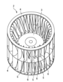
- Fig. 2 is a perspective view of an impeller 2 of the multi-blade centrifugal blower 1 according to the first embodiment.
- the multi-blade centrifugal blower 1 of this embodiment has an impeller 2 and a scroll casing 11 that houses the impeller 2.
- the impeller 2 has a disk-shaped main plate 3, an annular side plate 4, and a plurality of blades installed between the main plate 3 and the side plate 4.
- the main plate 3 and the side plate 4 are arranged concentrically with respect to the center of rotation of the impeller 2.
- the scroll casing 11 has a peripheral wall formed in a spiral shape and a bell mouth that forms an intake port that communicates with the space formed by the main plate 3 and multiple blades of the impeller 2.
- the bell mouth is used to smoothly draw in the airflow from the intake port of the scroll casing 11.
- the impeller 2 in this embodiment has two side plates 4, and the main plate 3 is disposed between the two side plates 4.
- This disclosure is not limited to such a configuration, and the impeller 2 may have only one side plate 4.
- the multiple blades of the impeller 2 include a first blade 5 and a second blade 6. At least on the main plate 3 side, the outer diameter of the first blade 5 is larger than the outer diameter of the second blade 6. Furthermore, the outer diameter of the second blade 6 on the main plate 3 side is smaller than the outer diameter of the second blade 6 on the side plate 4 side. Note that the multiple blades of the impeller 2 may include blades other than the first blade 5 and the second blade 6.
- the first blade 5 on the main plate 3 side means the portion of the first blade 5 that is closer to the main plate 3 than the side plate 4.
- the first blade 5 on the side plate 4 side means the portion of the first blade 5 that is closer to the side plate 4 than the main plate 3.
- the second blade 6 on the main plate 3 side means the portion of the second blade 6 that is closer to the main plate 3 than the side plate 4.
- the second blade 6 on the side plate 4 side means the portion of the second blade 6 that is closer to the side plate 4 than the main plate 3.
- the multi-blade centrifugal blower 1 of the present embodiment 1 has the following effect through the following mechanism. At least on the main plate 3 side, the outer diameter of the first blade 5 is larger than the outer diameter of the second blade 6, and the outer diameter of the second blade 6 on the main plate 3 side is smaller than the outer diameter of the second blade 6 on the side plate 4 side. This generates a fast flow on the main plate 3 side in the first blade 5, maintaining the air volume on the main plate 3 side, and the air flow on the side plate 4 side is increased by guiding the air flow to the side plate 4 side in the second blade 6 along the expansion of the outer diameter.
- the first blade 5 has the characteristic of a fast wind speed on the main plate 3 side, and ensures the air volume.
- the second blade 6 flows air from the main plate 3 side to the side plate 4 side, increasing the air volume on the side plate 4 side and making the wind speed distribution on the outer periphery uniform, allowing the entire area inside the scroll casing 11 to be used effectively, and allowing for an efficient change from dynamic pressure to static pressure, leading to improved input.
- the outer diameter of the first blade 5 on the main plate 3 side may be equal to the outer diameter of the first blade 5 on the side plate 4 side. If the outer diameter of the first blade 5 on the main plate 3 side is equal to the outer diameter of the first blade 5 on the side plate 4 side, the above-mentioned effects can be achieved more reliably.
- Embodiment 2 Next, a second embodiment will be described with reference to Figures 3 and 4, with the focus on differences from the first embodiment described above, and explanations of commonalities will be simplified or omitted. Also, elements common to or corresponding to the elements described above will be given the same reference numerals.
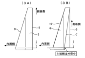
- FIG. 3 is a diagram showing the first blade 5 and the second blade 6 in embodiment 2.
- FIG. 3A shows the first blade 5.
- FIG. 3B shows the second blade 6.
- the second blade 6 has a smaller outer diameter in at least a portion on the main plate 3 side than on the side plate 4 side.
- the outer diameter of the second blade 6 and the outer diameter of the first blade 5 may be the same or different.
- the outer diameter of the second blade 6 at the portion in contact with the side plate 4 is equal to the outer diameter of the first blade 5 at the portion in contact with the side plate 4.
- the outer diameter of the second blade 6 gradually increases from the main plate 3 toward the side plate 4.
- the outer diameter of the second blade 6 is a value equivalent to twice the distance between the outer edge 7 of the second blade 6 and the rotation center line of the impeller 2. In this way, the outer diameter of the second blade 6 on the side plate 4 side may be equal to the outer diameter of the first blade 5 on the side plate 4 side.
- the outer diameter of the first blade 5 is constant along the rotation axis direction.
- the rotation axis direction is a direction parallel to the rotation center line of the impeller 2.
- the outer diameter of the first blade 5 is a value equivalent to twice the distance between the outer edge 8 of the first blade 5 and the rotation center line of the impeller 2.
- the inner diameter of the first blade 5 gradually decreases from the main plate 3 toward the side plate 4.
- the inner diameter of the second blade 6 also gradually decreases from the main plate 3 toward the side plate 4.
- the inner diameter of the first blade 5 is a value equivalent to twice the distance between the inner edge 9 of the first blade 5 and the rotation center line of the impeller 2.
- the inner diameter of the second blade 6 is a value equivalent to twice the distance between the inner edge 10 of the second blade 6 and the rotation center line of the impeller 2.
- the inner diameter of the first blade 5 is equal to the inner diameter of the second blade 6.
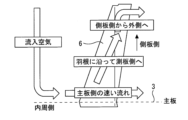
- FIG. 4 is a diagram showing the flow at the second blade 6. As shown in Figure 4, the second blade 6 is inclined toward the side plate 4 side on the outside where the wind speed is faster. This causes the air that has entered the main plate 3 side to flow along the second blade 6 to the side plate 4 side. As a result, the amount of air on the side plate 4 side can be increased, which is more advantageous in making the speed distribution on the outer periphery side of the impeller 2 uniform.
- Embodiment 3 Next, a third embodiment will be described with reference to Fig. 5. The differences from the first embodiment will be mainly described, and the description of the common parts will be simplified or omitted. The same reference numerals will be used to denote the common parts or parts corresponding to the above-described first embodiment.
- FIG. 5 shows the first blade 5 and the second blade 6 in the third embodiment.
- FIG. 5A shows the first blade 5.
- FIG. 5B shows the second blade 6.
- the inner diameter of the second blade 6 is smaller than the inner diameter of the first blade 5.
- the inner diameter of the second blade 6 is equal to the inner diameter of the first blade 5 as in embodiment 2, the blade area of the second blade 6 is small, and the air volume decreases.
- the inner diameter of the second blade 6 is smaller than the inner diameter of the first blade 5, and the blade area of the second blade 6 is large. As a result, it is possible to prevent a decrease in the air volume and maintain the air volume. Note that the above effect can be obtained if the inner diameter of the second blade 6 is smaller than the inner diameter of the first blade 5, at least in a portion on the main plate 3 side.
- Embodiment 4 Next, a fourth embodiment will be described with reference to Fig. 6, focusing on the differences from the first embodiment described above, and the description of the commonalities will be simplified or omitted. Also, the same reference numerals will be used to designate the common or corresponding elements to the elements described above.
- FIG. 6 is a diagram showing the exit angles of the first blade 5 and the second blade 6.
- FIG. 6A shows the exit angle on the main plate 3 side
- FIG. 6B shows the exit angle on the side plate 4 side.
- the value of the exit angle ⁇ 2 of the second blade 6 on the main plate 3 side is different from the value of the exit angle ⁇ 2 of the second blade 6 on the side plate 4 side, and ⁇ 2 ⁇ 2.
- the relationship between the exit angle ⁇ 2 and the exit angle ⁇ 2 is such that ⁇ 2 ⁇ 2 holds when the exit angle angle is positive or negative, i.e., when the forward advance angle is a positive angle value and the reverse advance angle is a negative angle value.
- the relationship ⁇ 2 ⁇ 2 is not the relationship between the absolute value of the exit angle ⁇ 2 and the absolute value of the exit angle ⁇ 2, but takes into account the definition of positive and negative at the exit angle.
- the air can be guided to the side plate 4 side at the outermost diameter of the second blade 6, and the air that has entered the main plate 3 side can be made to flow to the side plate 4 side.
- the air volume on the side plate 4 side can be increased more reliably, which is more advantageous in making the speed distribution on the outer periphery side of the impeller 2 uniform.
- Embodiment 5 Next, a fifth embodiment will be described with reference to Fig. 6 and Fig. 7, focusing on the differences from the first embodiment and simplifying or omitting the description of the common parts. Also, the same reference numerals are used to denote the common parts or parts corresponding to the above-mentioned first embodiment.
- the exit angle of the second blade 6 on the main plate 3 side is a forward or reverse angle
- the exit angle of the second blade 6 on the side plate 4 side is a forward angle
- the second blade 6 is a forward-swept blade on the side plate 4 side, making it possible to ensure sufficient air volume.
- the outlet angle of the second blade 6 on the main plate 3 side forward or backward, air can be guided to the first blade 5 more efficiently.
- Figure 7 is a diagram showing an image of the airflow in embodiment 5.
- the second blade 6 on the side panel 4 side is a forward-swept blade, so air volume can be ensured.
- Figure 7A air can be guided to the first blade 5 on the main panel 3 side.
- Embodiment 6. 6 and 7, a sixth embodiment will be described, focusing on the differences from the first embodiment and simplifying or omitting the description of the common parts.
- the same reference numerals are used to denote the common parts or parts corresponding to the first embodiment.
- the value of the exit angle ⁇ 1 of the first blade 5 on the side panel 4 side is equal to the value of the exit angle ⁇ 2 of the second blade 6 on the side panel 4 side.
- the relationship between the value of the exit angle ⁇ 1 and the value of the exit angle ⁇ 2 here holds even when the exit angle is positive or negative, i.e., when the forward advance angle is a positive angle value and the rearward advance angle is a negative angle value.
- the exit angle ⁇ 1 is a forward advance angle
- the exit angle ⁇ 2 is also a rearward advance angle
- the exit angle ⁇ 1 is a rearward advance angle
- the exit angle ⁇ 2 is also a rearward advance angle.
- the outlet angles of the first blade 5 and the second blade 6 on the side plate 4 side are aligned to unify the flow direction and reduce loss between the scroll casing 11. Note that the same effect can be obtained even when the outlet angle of the first blade 5 on the side plate 4 side and the outlet angle of the second blade 6 on the side plate 4 side are both forward angles or both backward angles.
- Embodiment 7 Next, a seventh embodiment will be described with reference to Figures 6 to 8, with the differences from the first embodiment being mainly described, and the description of the commonalities will be simplified or omitted. Also, the same reference numerals will be used to denote the common or corresponding elements to the elements described above.
- the absolute value of the outlet angle ⁇ 2 of the second blade 6 on the main plate 3 side is smaller than the absolute value of the outlet angle ⁇ 1 of the first blade 5 on the main plate 3 side.
- Figure 8 is a diagram showing an image of the flow when the absolute value of the outlet angle of the second blade 6 on the main plate 3 side is large. As shown in Figure 8, when the absolute value of the outlet angle of the second blade 6 on the main plate 3 side is large, the air flowing along the second blade 6 collides with the first blade 5 and is lost.
- the above loss can be reduced by reducing the absolute value of the outlet angle of the second blade 6 on the main plate 3 side.
- the multi-blade centrifugal blower of embodiment 7 can reduce losses caused by the airflow colliding with the first blade 5 by making the absolute value of the outlet angle of the second blade 6 on the main plate 3 side smaller than that of the first blade 5.
- Embodiment 8 Next, an eighth embodiment will be described with reference to Fig. 9, focusing on the differences from the first embodiment described above, and the description of the commonalities will be simplified or omitted. Also, the same reference numerals will be used to designate the common or corresponding elements to the elements described above.
- FIG. 9 is a perspective view of the impeller 2 according to embodiment 8. As shown in FIG. 9, in embodiment 8, the first blades 5 and the second blades 6 are arranged alternately one by one along the circumferential direction.
- the first blade 5 maintains the air volume on the main plate 3 side
- the second blade 6 increases the air volume on the side plate 4 side.
- Figure 10 is a diagram showing an image of the flow in embodiment 8. As shown in Figure 10, in this embodiment, the inlet is widened and then redistributed, ensuring the flow rate while smoothly converting dynamic pressure to static pressure.
- the multi-blade centrifugal blower of embodiment 8 can maintain the air volume on the main plate 3 side with the first blade 5, and increase the air volume on the side plate 4 side with the second blade 6. In addition, by widening the inlet and then redistributing it, the flow rate can be secured while smoothly converting dynamic pressure to static pressure.
- Embodiment 9 Next, a ninth embodiment will be described with reference to Fig. 11, focusing on the differences from the first embodiment described above, and the description of the commonalities will be simplified or omitted. Also, the same reference numerals will be used to designate the common or corresponding elements to the elements described above.
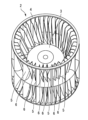
- FIG. 11 is a perspective view of an impeller 2 according to embodiment 9. As shown in FIG. 11, in embodiment 9, a plurality of first blades 5 and a single second blade 6 are arranged alternately along the circumferential direction. In the illustrated example, two first blades 5 and one second blade 6 are arranged alternately and periodically along the circumferential direction.
- a multi-blade centrifugal blower 1 configured in this way, by arranging more first blades 5 than second blades 6, the inlet can be enlarged, the air volume can be improved, and the rotation speed can be reduced.
- Embodiment 10 Next, a tenth embodiment will be described with reference to Fig. 12, focusing on the differences from the first embodiment described above, and the description of the commonalities will be simplified or omitted. Also, the same reference numerals will be used to designate the common or corresponding elements to the elements described above.
- FIG. 12 is a perspective view of an impeller 2 according to embodiment 10. As shown in FIG. 12, in embodiment 10, a single first blade 5 and multiple second blades 6 are arranged alternately along the circumferential direction. In the illustrated example, one first blade 5 and two second blades 6 are arranged alternately and periodically along the circumferential direction.
- a multi-blade centrifugal blower 1 configured in this manner, by making the number of second blades 6 greater than the number of first blades 5, it is possible to improve the torque value by reducing the blade area.
- the air conditioner according to the present disclosure is equipped with the multi-blade centrifugal blower 1 as described above.
- the air conditioner has an outdoor unit and an indoor unit.
- the outdoor unit may be equipped with the multi-blade centrifugal blower 1, or the indoor unit may be equipped with the multi-blade centrifugal blower 1.
- the air conditioner according to the present disclosure may be one in which the multi-blade centrifugal blower 1 blows air to an outdoor heat exchanger that exchanges heat between outdoor air and a refrigerant, or one in which the multi-blade centrifugal blower 1 blows air to an indoor heat exchanger that exchanges heat between indoor air and a refrigerant.
Landscapes
- Engineering & Computer Science (AREA)
- Mechanical Engineering (AREA)
- General Engineering & Computer Science (AREA)
- Structures Of Non-Positive Displacement Pumps (AREA)
Priority Applications (4)
| Application Number | Priority Date | Filing Date | Title |
|---|---|---|---|
| DE112023006221.8T DE112023006221T5 (de) | 2023-04-18 | 2023-04-18 | Mehrflügeliges zentrifugalgebläse und klimaanlage |
| PCT/JP2023/015464 WO2024218857A1 (ja) | 2023-04-18 | 2023-04-18 | 多翼遠心送風機及び空気調和機 |
| CN202380097075.3A CN120936811A (zh) | 2023-04-18 | 2023-04-18 | 多翼式离心送风机以及空调机 |
| JP2025514922A JPWO2024218857A1 (https=) | 2023-04-18 | 2023-04-18 |
Applications Claiming Priority (1)
| Application Number | Priority Date | Filing Date | Title |
|---|---|---|---|
| PCT/JP2023/015464 WO2024218857A1 (ja) | 2023-04-18 | 2023-04-18 | 多翼遠心送風機及び空気調和機 |
Publications (1)
| Publication Number | Publication Date |
|---|---|
| WO2024218857A1 true WO2024218857A1 (ja) | 2024-10-24 |
Family
ID=93152149
Family Applications (1)
| Application Number | Title | Priority Date | Filing Date |
|---|---|---|---|
| PCT/JP2023/015464 Ceased WO2024218857A1 (ja) | 2023-04-18 | 2023-04-18 | 多翼遠心送風機及び空気調和機 |
Country Status (4)
| Country | Link |
|---|---|
| JP (1) | JPWO2024218857A1 (https=) |
| CN (1) | CN120936811A (https=) |
| DE (1) | DE112023006221T5 (https=) |
| WO (1) | WO2024218857A1 (https=) |
Citations (2)
| Publication number | Priority date | Publication date | Assignee | Title |
|---|---|---|---|---|
| JPH0539930A (ja) * | 1991-08-02 | 1993-02-19 | Daikin Ind Ltd | 空気調和装置 |
| JPH1193893A (ja) * | 1997-09-25 | 1999-04-06 | Denso Corp | 遠心多翼ファン |
Family Cites Families (1)
| Publication number | Priority date | Publication date | Assignee | Title |
|---|---|---|---|---|
| JP2014029149A (ja) | 2012-06-26 | 2014-02-13 | Denso Corp | 遠心式多翼送風機 |
-
2023
- 2023-04-18 JP JP2025514922A patent/JPWO2024218857A1/ja active Pending
- 2023-04-18 WO PCT/JP2023/015464 patent/WO2024218857A1/ja not_active Ceased
- 2023-04-18 CN CN202380097075.3A patent/CN120936811A/zh active Pending
- 2023-04-18 DE DE112023006221.8T patent/DE112023006221T5/de active Pending
Patent Citations (2)
| Publication number | Priority date | Publication date | Assignee | Title |
|---|---|---|---|---|
| JPH0539930A (ja) * | 1991-08-02 | 1993-02-19 | Daikin Ind Ltd | 空気調和装置 |
| JPH1193893A (ja) * | 1997-09-25 | 1999-04-06 | Denso Corp | 遠心多翼ファン |
Also Published As
| Publication number | Publication date |
|---|---|
| DE112023006221T5 (de) | 2026-03-19 |
| JPWO2024218857A1 (https=) | 2024-10-24 |
| CN120936811A (zh) | 2025-11-11 |
Similar Documents
| Publication | Publication Date | Title |
|---|---|---|
| US9062888B2 (en) | Air conditioner | |
| US9382912B2 (en) | Fan, molding die, and fluid feeder | |
| JP4690682B2 (ja) | 空調機 | |
| JP6129431B1 (ja) | 送風機およびこの送風機を搭載した空気調和装置 | |
| US20110017427A1 (en) | Blower and heatpump using the same | |
| EP3591236A1 (en) | Propeller fan, blower, and air conditioner | |
| JPH1144432A (ja) | 空気調和機 | |
| JP5293684B2 (ja) | 空気調和機の室内機 | |
| JP5024349B2 (ja) | 送風機及びこれを用いた空気調和機並びに空気清浄機 | |
| JP2009281215A (ja) | 空気調和機用室内機 | |
| WO2024218857A1 (ja) | 多翼遠心送風機及び空気調和機 | |
| JP2012107848A (ja) | 空気調和機の室内ユニット | |
| JP4872997B2 (ja) | 送風機及び該送風機を備えた空気調和機 | |
| CN110914550B (zh) | 空调机的室内机 | |
| JPWO2018131077A1 (ja) | 空気調和機の室外機 | |
| JP2010236371A (ja) | 軸流送風機、空気調和機及び換気扇 | |
| JPWO2015064617A1 (ja) | 貫流ファン及び空気調和機 | |
| CN113906220A (zh) | 轴流风扇、送风装置及制冷循环装置 | |
| WO2024009466A1 (ja) | 軸流ファン、送風機、室外機、及び、空気調和機 | |
| JP6625213B2 (ja) | 多翼ファン及び空気調和機 | |
| JP7798154B1 (ja) | 遠心ファン及びこれを備えた空気調和機 | |
| JPH07286598A (ja) | 流体ディフレクタ付遠心ファン | |
| US20240068486A1 (en) | Scroll casing, and air-sending device and air-conditioning apparatus which include the same | |
| JPWO2015063851A1 (ja) | 貫流ファン及び空気調和機 | |
| US20260126056A1 (en) | Impeller, fan, and air handler |
Legal Events
| Date | Code | Title | Description |
|---|---|---|---|
| 121 | Ep: the epo has been informed by wipo that ep was designated in this application |
Ref document number: 23934003 Country of ref document: EP Kind code of ref document: A1 |
|
| WWE | Wipo information: entry into national phase |
Ref document number: 2025514922 Country of ref document: JP |
|
| WWE | Wipo information: entry into national phase |
Ref document number: 112023006221 Country of ref document: DE |
|
| WWP | Wipo information: published in national office |
Ref document number: 112023006221 Country of ref document: DE |
|
| 122 | Ep: pct application non-entry in european phase |
Ref document number: 23934003 Country of ref document: EP Kind code of ref document: A1 |