WO2024218819A1 - 金属ターミナル用インサート成形品 - Google Patents
金属ターミナル用インサート成形品 Download PDFInfo
- Publication number
- WO2024218819A1 WO2024218819A1 PCT/JP2023/015298 JP2023015298W WO2024218819A1 WO 2024218819 A1 WO2024218819 A1 WO 2024218819A1 JP 2023015298 W JP2023015298 W JP 2023015298W WO 2024218819 A1 WO2024218819 A1 WO 2024218819A1
- Authority
- WO
- WIPO (PCT)
- Prior art keywords
- terminal
- metal terminal
- welding
- molded product
- metal
- Prior art date
- Legal status (The legal status is an assumption and is not a legal conclusion. Google has not performed a legal analysis and makes no representation as to the accuracy of the status listed.)
- Ceased
Links
Images







Classifications
-
- B—PERFORMING OPERATIONS; TRANSPORTING
- B23—MACHINE TOOLS; METAL-WORKING NOT OTHERWISE PROVIDED FOR
- B23K—SOLDERING OR UNSOLDERING; WELDING; CLADDING OR PLATING BY SOLDERING OR WELDING; CUTTING BY APPLYING HEAT LOCALLY, e.g. FLAME CUTTING; WORKING BY LASER BEAM
- B23K11/00—Resistance welding; Severing by resistance heating
-
- B—PERFORMING OPERATIONS; TRANSPORTING
- B23—MACHINE TOOLS; METAL-WORKING NOT OTHERWISE PROVIDED FOR
- B23K—SOLDERING OR UNSOLDERING; WELDING; CLADDING OR PLATING BY SOLDERING OR WELDING; CUTTING BY APPLYING HEAT LOCALLY, e.g. FLAME CUTTING; WORKING BY LASER BEAM
- B23K11/00—Resistance welding; Severing by resistance heating
- B23K11/10—Spot welding; Stitch welding
- B23K11/11—Spot welding
Definitions
- This application relates to an insert molded product for metal terminals that is joined to the terminals of other components by welding.
- a conventional sensor device used to detect the rotation of various rotating objects to be detected in vehicle engines or general machinery is, for example, a magnetic detection device as shown in Patent Document 1.
- the description therein describes a sensor device that includes a detection module arranged to face the object to be detected, an insert molded product including a metal terminal to which the detection module is connected, and an exterior molded part in which these are integrated into one piece by resin molding.
- the component terminal of the detection module and one of the metal terminals of the insert molded product are joined by resistance welding.
- the other end of this metal terminal serves as the terminal of a connector formed by the exterior molded part.
- the durability of the sensor device is affected by the reliability of the welds applied to the joints between the component terminals of the detection module and the metal terminals, so it is important to increase the reliability of the resistance welds applied to the joints.
- resistance welding is used in which the joint of the metal terminal of the insert molding and the component terminal of the detection module are overlapped and sandwiched between welding electrodes from both sides, a welding current is passed through them, and the metal is melted and diffused by resistance heating to join them.
- the temperature of the welding electrode also rises, so that the contact point of the resin body of the insert molding that comes into contact with the welding electrode melts, causing the resin to adhere to the welding electrode, resulting in a problem of reduced welding reliability in continuous welding work.
- the present application aims to prevent welding electrode contamination due to resin melting during resistance welding in an insert molded product for a metal terminal, and to improve welding reliability in continuous welding operations.
- the insert molded product for metal terminals is an insert molded product for metal terminals that includes a metal terminal provided with a terminal portion having a joint portion that is joined to the terminal of another component, and a resin body that supports the metal terminal, and the terminal portion is formed with a structure for separating a welding electrode for welding the joint portion from the resin body.
- a structure is provided at the terminal portion of the metal terminal for separating the welding electrode for welding the joint from the resin body, so that the welding electrode does not come into contact with the resin portion of the insert molded product, preventing resin from adhering to the welding electrode during continuous welding operations and ensuring welding reliability.
- 1 is a perspective view showing a metal terminal of an insert-molded product for a metal terminal according to a first embodiment
- 1 is a perspective view showing the appearance of an insert molding for a metal terminal according to a first embodiment
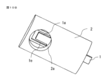
- 2B is a perspective view showing the appearance of the insert-molded product for a metal terminal according to the first embodiment, as viewed from the opposite side to FIG. 2A.
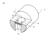
- 1 is a perspective view showing a cross section of an insert-molded product for a metal terminal according to a first embodiment, cut at a terminal portion of the metal terminal
- 1 is a cross-sectional perspective view showing a state immediately before welding a component terminal of a detection module to an insert molding for a metal terminal according to a first embodiment.
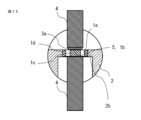
- FIG. 4 is a cross-sectional view showing a state of the insert-molded product for a metal terminal according to the first embodiment during welding.
- FIG. 11 is a perspective view showing a metal terminal of an insert-molded product for a metal terminal according to a second embodiment of the present invention.
- FIG. 11 is a perspective view showing the appearance of an insert molding for a metal terminal according to a second embodiment;
- FIG. 7B is a perspective view showing the appearance of the insert-molded product for a metal terminal according to the second embodiment, as viewed from the opposite side to FIG. 7A.
- 11 is a perspective view showing a cross section of an insert-molded product for a metal terminal according to a second embodiment, cut at a terminal portion of the metal terminal.
- FIG. 11 is a perspective view showing a metal terminal of an insert-molded product for a metal terminal according to a second embodiment of the present invention.
- FIG. 11 is a perspective view showing the appearance of an insert molding for a metal terminal according to a second embodiment
- FIG. 11 is a cross-sectional view showing a state of a metal terminal insert molding according to a second embodiment during welding.
- FIG. 13 is a perspective view showing the appearance of an insert molding for a metal terminal according to a third embodiment;
- FIG. 10B is a perspective view showing the appearance of the insert-molded product for a metal terminal according to the third embodiment, as viewed from the opposite side to FIG. 10A.
- 13 is a perspective view showing a cross section of an insert-molded product for a metal terminal according to a third embodiment, cut at a terminal portion of the metal terminal.
- FIG. 13 is a cross-sectional view showing a state of an insert molding for a metal terminal according to embodiment 3 during welding.
- FIG. 13 is a perspective view showing a metal terminal of an insert molding for a metal terminal according to a fourth embodiment
- FIG. 13B is a perspective view of the metal terminal of the insert-molded product for a metal terminal according to the fourth embodiment, seen from the opposite side of FIG. 13A.
- FIG. 13 is a perspective view showing a cross section of a metal terminal of an insert-molded product for a metal terminal according to a fourth embodiment, cut at a terminal portion.
- FIG. 13 is a perspective view showing the appearance of an insert molding for a metal terminal according to a fourth embodiment
- FIG. 14B is a perspective view showing the appearance of the insert-molded product for a metal terminal according to the fourth embodiment, as viewed from the opposite side to FIG. 14A.
- FIG. 13 is a perspective view showing a cross section of an insert molding for a metal terminal according to a fourth embodiment, cut at a terminal portion of the metal terminal.
- FIG. 13 is a cross-sectional view showing a state of a metal terminal insert molding according to a fourth embodiment during welding.
- FIG. 13 is a perspective view showing a metal terminal of an insert molding for a metal terminal according to a fifth embodiment.
- FIG. 17B is a perspective view of the metal terminal of the insert-molded product for a metal terminal according to the fifth embodiment, seen from the opposite side to FIG. 17A.
- FIG. 13 is a perspective view showing the appearance of an insert molding for a metal terminal according to a fifth embodiment.
- FIG. 18B is a perspective view showing the appearance of the insert-molded product for a metal terminal according to the fifth embodiment, as viewed from the opposite side to FIG. 18A.
- 13 is a perspective view showing a cross section of an insert-molded product for a metal terminal according to a fifth embodiment, cut at a terminal portion of the metal terminal.
- FIG. 13 is a cross-sectional view showing the state during insert molding of the metal terminal insert-molded product according to the fifth embodiment.
- FIG. 13 is a cross-sectional view showing a state of a metal terminal insert molding according to a fifth embodiment during welding.
- FIG. 13 is a perspective view showing a metal terminal of an insert molding for a metal terminal according to a sixth embodiment of the present invention.
- FIG. 13 is a perspective view showing the appearance of an insert molding for a metal terminal according to a sixth embodiment of the present invention
- FIG. 23B is a perspective view showing the appearance of the insert-molded product for a metal terminal according to the sixth embodiment, as viewed from the opposite side to that of FIG. 23A.
- 13 is a perspective view showing a cross section of an insert-molded product for a metal terminal according to a sixth embodiment, cut at a terminal portion of the metal terminal.
- FIG. 13 is a perspective view showing the appearance of an insert molding for a metal terminal according to a seventh embodiment of the present invention; FIG.
- Fig. 1 shows a metal terminal 1 of the insert molded product for metal terminal according to the first embodiment.
- the metal terminal 1 is a flat metal terminal, and is integrally molded and embedded in a resin body 2 as shown in Fig. 2A to become an insert molded product for metal terminal.
- a joint 1b to be joined to another part terminal is provided on the surface of a terminal portion 1a which is the tip of the metal terminal 1.
- Fig. 3 shows a cross section of the insert molded product for metal terminal cut at the terminal portion 1a, and the terminal portion 1a which is the tip of the metal terminal 1 is supported at its outer edge by a protruding portion 2b of the resin body 2.
- FIG. 4 is a cross-sectional perspective view showing a state immediately before welding the component terminal 3a of the detection module 3 to the terminal portion 1a of this insert molding for a metal terminal.
- the terminal portion 1a and the component terminal 3a are sandwiched between a pair of welding electrodes 4, and the joint portion 1b of the terminal portion 1a and the component terminal 3a are welded at a weld portion 5 by resistance welding.
- 5, the component terminal 3a of the detection module 3 and the terminal portion 1a of the metal terminal 1 of the insert molding are overlapped, sandwiched from both sides by the welding electrodes 4, a current for welding is passed, resistance welding is performed at the welding portion 5, and the terminal portion 1a is joined at the joint portion 1b.
- the terminal portion 1a of the metal terminal 1 and the welding electrode 4 come into contact with each other, but a separation distance is maintained between the surface of the welding electrode 4 and the opposing overhanging portion 2b of the resin body 2. Since the thickness of the terminal portion 1a is greater than the thickness of the overhanging portion 2b of the resin body 2 supporting the outer edge of the terminal portion 1a, a separation structure is formed in which the welding electrode 4 and the resin body 2 are separated from each other.
- Embodiment 2 An insert molded product for a metal terminal according to a second embodiment of the present invention will be described with reference to Fig. 6 to Fig. 9. Note that parts corresponding to the components of the first and second embodiments are indicated by the same reference numerals, and detailed description thereof will be omitted.
- 6 shows the metal terminal 1 used in the second embodiment, in which the terminal portion 1a has a central portion 1c including a joint portion 1b at its center, and a peripheral portion 1d is provided so as to surround the central portion 1c.
- the central portion 1c is connected to the other portion of the metal terminal 1, and a gap 1e is formed between the central portion 1c and the peripheral portion 1d.
- the terminal portion 1a When insert molding the metal terminal 1 with the resin body 2, the terminal portion 1a is sandwiched between the molding die, making it easy to realize an insert molded product in which there is no resin (is a space) in the gap 1e between the center portion 1c and the surrounding peripheral portion 1d.
- Fig. 7A shows the appearance of the insert molded product for a metal terminal using this metal terminal 1
- Fig. 7B the rear view shows the gap 1e of the terminal portion 1a through the opening 2a of the resin body 2.
- the opening 2a is shown as having a rectangular shape in accordance with the outer edge of the terminal portion 1a.
- Fig. 8 is a perspective view showing a cross section of the insert molded product for a metal terminal according to the second embodiment cut at the terminal portion 1a.
- FIG. 9 is a cross-sectional view showing the state during welding, in which the welding electrode 4 comes into contact with the center 1c of the terminal portion 1a, and a separation structure is formed between the welding electrode 4 and the resin body 2, with the space of the gap 1e and the peripheral portion 1d separating them.
- the welding electrode 4 and the resin body 2 are maintained apart in this manner, adhesion of resin to the welding electrode 4 can be prevented even if the welding electrode 4 becomes hot during welding, and welding reliability can be ensured during continuous welding operations.
- the terminal portion 1a of the metal terminal 1 that contacts the surface of the welding electrode 4 is limited to the central portion 1c, the volume of the joint portion 1b is also reduced and the heat capacity is also reduced, making it possible to reduce the welding energy required for joining.
- the resin body 2 not only supports the terminal portion 1a at its outer edge, but also has an opening 2a formed in the resin body 2 so as to support the peripheral portion 1d from below, thereby improving the strength with which the metal terminal 1 is supported.
- Embodiment 3 An insert molded product for a metal terminal according to a third embodiment of the present invention will be described with reference to Fig. 10A to Fig. 12. Note that parts corresponding to the components of the first and second embodiments are indicated by the same reference numerals, and detailed description thereof will be omitted.
- the shape of the metal terminal 1 in the third embodiment is the same as that of the metal terminal in the second embodiment shown in Fig. 6.
- Fig. 10A shows the appearance of the insert molded product for a metal terminal using this metal terminal 1, which is the same as Fig. 7A of the second embodiment.
- the opening 2a has a round shape exposing the terminal portion 1a, and has a different structure from the resin body 2 in the second embodiment.
- FIG. 11 is a perspective view showing a cross section of the insert molded product for metal terminals according to the third embodiment cut at the terminal portion 1a.
- the peripheral portion 1d of the terminal portion 1a of the metal terminal 1 is in contact with the protruding portion 2b of the resin body 2.
- the outer edge of the peripheral portion 1d surrounding the terminal portion 1a becomes the seal portion 2c of the resin body 2. Since the thickness of the peripheral portion 1d is the same as the thickness of the protruding portion 2b of the resin body 2 supporting the outer edge of the terminal portion 1a, the entire surface of the peripheral portion 1d surrounding the terminal portion 1a can be molded while being pressed by a mold during the insert molding of the metal terminal 1.
- FIG. 12 is a cross-sectional view showing the state during welding, in which the welding electrode 4 comes into contact with the center 1c of the terminal portion 1a, and a separation structure is formed between the welding electrode 4 and the resin body 2, with the space of the gap 1e and the peripheral portion 1d separating them. Furthermore, by providing the protruding portion 2b of the resin body 2, the separation distance between the welding electrode 4 and the resin body 2 can be kept large.
- the welding electrode 4 and the resin body 2 are maintained apart in this manner, adhesion of resin to the welding electrode 4 can be prevented even if the welding electrode 4 becomes hot during welding, and welding reliability can be ensured during continuous welding operations.
- the terminal portion 1a of the metal terminal 1 that contacts the surface of the welding electrode 4 is limited to the central portion 1c, the volume of the joint portion 1b is also reduced and the heat capacity is also reduced, making it possible to reduce the welding energy required for joining.
- Embodiment 4 An insert molding for a metal terminal according to a fourth embodiment of the present invention will be described with reference to Fig. 13A to Fig. 16. Note that parts corresponding to the components of the first to third embodiments are indicated by the same reference numerals, and detailed description thereof will be omitted.
- Fig. 13A shows the appearance of the metal terminal 1 in the fourth embodiment
- Fig. 13B shows the appearance from the opposite side
- Fig. 13C is a perspective view showing a cross section of the terminal portion 1a.
- the joint portion 1b is the front surface of the terminal portion 1a, and the back surface is partitioned by a groove 1f to form a central portion 1c, and a peripheral portion 1d is formed so as to surround the central portion 1c.
- Fig. 14A shows the appearance of the insert-molded product for a metal terminal made of this metal terminal 1, and in the appearance from the back side of Fig. 14B, the groove 1f of the terminal portion 1a can be seen through the opening 2a of the resin body 2.
- Fig. 15 is a perspective view showing a cross section of the insert-molded product for a metal terminal of this embodiment 4 cut at the terminal portion 1a.
- FIG. 16 is a cross-sectional view showing the state during welding, in which the welding electrode 4 comes into contact with the center 1c of the terminal portion 1a, and a separation structure is formed between the welding electrode 4 and the resin body 2, with the space of the groove 1f and the peripheral portion 1d separating them.
- the welding electrode 4 and the resin body 2 are maintained apart in this manner, adhesion of resin to the welding electrode 4 can be prevented even if the welding electrode 4 becomes hot during welding, and welding reliability can be ensured during continuous welding operations.
- the terminal portion 1a of the metal terminal 1 that contacts the surface of the welding electrode 4 is limited to the central portion 1c separated by the groove 1f, so the volume of the joint portion 1b is also reduced and the heat capacity is also reduced, making it possible to reduce the welding energy required for joining.
- FIG. 17A shows the appearance of the metal terminal 1 in the embodiment 4
- Fig. 17B shows the appearance seen from the opposite side.
- the metal terminal 1 in the embodiment 5 is characterized in that the thickness of the center 1c of the terminal portion 1a is smaller than the thickness of the peripheral portion 1d surrounding the center 1c.
- Fig. 18A shows the appearance of the insert-molded product for a metal terminal made of this metal terminal 1, and in the appearance from the back side of Fig. 18B, the gap 1e of the terminal portion 1a can be seen through the opening 2a of the resin body 2.
- Fig. 19 is a perspective view showing a cross section of the insert-molded product for a metal terminal of this embodiment 5 cut at the terminal portion 1a.
- FIG. 20 is a cross-sectional view showing the state when the metal terminal 1 in the fifth embodiment is insert-molded.
- the metal terminal 1 is sandwiched between the molds 6a and 6b from above and below, and resin is injected to perform insert molding.
- the thickness of the center 1c of the terminal portion 1a of the metal terminal 1 is smaller than the thickness of the peripheral portion 1d surrounding it, so that the contact of the molding die is reliable. Since the load tends to concentrate on the peripheral portion 1d during insert molding, the effect of the seal portion 2c of the resin body 2 described in the third embodiment becomes stronger.
- the resin can be easily sealed without being affected by the positional deviation of the metal terminal 1 during insert molding, and the creeping up of the resin to the joint portion 1b, the center portion 1c, and the gap 1e is suppressed.
- 21 is a cross-sectional view showing the state during welding, in which the welding electrode 4 comes into contact with the center 1c of the terminal portion 1a, and a separation structure is formed between the welding electrode 4 and the resin body 2, with the space of the gap 1e and the peripheral portion 1d separating them. Furthermore, by providing the protruding portion 2b of the resin body 2, the separation distance between the welding electrode 4 and the resin body 2 can be kept large.
- the welding electrode 4 and the resin body 2 are maintained apart in this manner, adhesion of resin to the welding electrode 4 can be prevented even if the welding electrode 4 becomes hot during welding, and welding reliability can be ensured during continuous welding operations.
- the terminal portion 1a of the metal terminal 1 that comes into contact with the surface of the welding electrode 4 is limited to the thinly molded central portion 1c, so the volume of the joint portion 1b is also reduced and the heat capacity is also reduced, making it possible to reduce the welding energy required for joining.
- FIG. 22 shows the metal terminal 1 used in the sixth embodiment, characterized in that the planar shape of the terminal portion 1a is circular.
- Fig. 22 there is a central portion 1c including a joint portion 1b at the center, and a peripheral portion 1d is provided so as to surround the central portion 1c.
- the central portion 1c is connected to other portions of the metal terminal 1, and a gap 1e is formed between the central portion 1c and the peripheral portion 1d.
- a circular molten portion is formed during joining, so by providing the joint portion 1b in the circular central portion 1c, the volume of the welded portion 5 can be reduced.
- Fig. 23A shows the appearance of the insert-molded product for a metal terminal made of this metal terminal 1, and in the appearance from the back side of Fig. 23B, the gap 1e of the terminal portion 1a can be seen through the opening 2a of the resin body 2.
- Fig. 24 is a perspective view showing a cross section of the insert-molded product for a metal terminal of this embodiment 6 cut at the terminal portion 1a.
- the welding in embodiment 6 has the same configuration as that in FIG. 12, which is a cross-sectional view showing the state during welding in embodiment 3.
- the welding electrode 4 comes into contact with the center 1c of the terminal portion 1a, and a separation structure is formed between the welding electrode 4 and the resin body 2, with the space of the gap 1e and the peripheral portion 1d separating them. Furthermore, the protruding portion 2b of the resin body 2 allows the separation distance between the welding electrode 4 and the resin body 2 to be kept large.
- the welding electrode 4 and the resin body 2 are maintained apart in this manner, adhesion of resin to the welding electrode 4 can be prevented even if the welding electrode 4 becomes hot during welding, and welding reliability can be ensured during continuous welding operations.
- the terminal portion 1a of the metal terminal 1 that contacts the surface of the welding electrode 4 is limited to the central portion 1c that is formed into a circular shape to match the shape of the welding portion 5. Therefore, the volume of the joint 1b is also reduced and the heat capacity is also reduced, making it possible to reduce the welding energy required for joining.
- Embodiment 7 An insert molded product for a metal terminal according to a seventh embodiment of the present invention will be described with reference to Fig. 25. Note that parts corresponding to the components of the first to sixth embodiments are designated by the same reference numerals, and detailed description thereof will be omitted.
- Fig. 25 is a perspective view showing the appearance of an insert-molded product for a metal terminal according to embodiment 7.
- the metal terminal 1 is provided with the circular terminal portion 1a, which is the same as that shown in embodiment 6.
- a protrusion 1g is provided at the joint portion 1b, which is the center of the center portion 1c of the terminal portion 1a.
- this projection 1g can be applied to the other embodiments, and the same effect can be obtained by providing the projection 1g on the joint 1b.
- the terminal portion 1a provided on the metal terminal 1 was a single one, but there are cases where multiple detection modules are joined to the metal terminal 1. In such cases, it is possible to deal with this by providing multiple terminal portions 1a on the metal terminal 1 that is insert molded into the metal terminal insert molded product, and providing multiple joint portions 1b that are joined to the component terminals 3a of the multiple detection modules 3. Even in such cases, it is possible to provide the configurations shown in the first to seventh embodiments of the present application, and similar effects can be obtained.
Landscapes
- Engineering & Computer Science (AREA)
- Mechanical Engineering (AREA)
- Injection Moulding Of Plastics Or The Like (AREA)
Priority Applications (2)
| Application Number | Priority Date | Filing Date | Title |
|---|---|---|---|
| JP2025514893A JPWO2024218819A1 (https=) | 2023-04-17 | 2023-04-17 | |
| PCT/JP2023/015298 WO2024218819A1 (ja) | 2023-04-17 | 2023-04-17 | 金属ターミナル用インサート成形品 |
Applications Claiming Priority (1)
| Application Number | Priority Date | Filing Date | Title |
|---|---|---|---|
| PCT/JP2023/015298 WO2024218819A1 (ja) | 2023-04-17 | 2023-04-17 | 金属ターミナル用インサート成形品 |
Publications (1)
| Publication Number | Publication Date |
|---|---|
| WO2024218819A1 true WO2024218819A1 (ja) | 2024-10-24 |
Family
ID=93152265
Family Applications (1)
| Application Number | Title | Priority Date | Filing Date |
|---|---|---|---|
| PCT/JP2023/015298 Ceased WO2024218819A1 (ja) | 2023-04-17 | 2023-04-17 | 金属ターミナル用インサート成形品 |
Country Status (2)
| Country | Link |
|---|---|
| JP (1) | JPWO2024218819A1 (https=) |
| WO (1) | WO2024218819A1 (https=) |
Citations (3)
| Publication number | Priority date | Publication date | Assignee | Title |
|---|---|---|---|---|
| JP2002219580A (ja) * | 2001-01-19 | 2002-08-06 | Fujitsu Ten Ltd | 抵抗溶接電極及び抵抗溶接される被溶接物並びに抵抗溶接方法 |
| JP2015003337A (ja) * | 2013-06-24 | 2015-01-08 | 株式会社デンソー | ターミナル溶接構造 |
| JP2020050827A (ja) * | 2018-09-28 | 2020-04-02 | マツダ株式会社 | 接合装置及び接合方法 |
-
2023
- 2023-04-17 JP JP2025514893A patent/JPWO2024218819A1/ja active Pending
- 2023-04-17 WO PCT/JP2023/015298 patent/WO2024218819A1/ja not_active Ceased
Patent Citations (3)
| Publication number | Priority date | Publication date | Assignee | Title |
|---|---|---|---|---|
| JP2002219580A (ja) * | 2001-01-19 | 2002-08-06 | Fujitsu Ten Ltd | 抵抗溶接電極及び抵抗溶接される被溶接物並びに抵抗溶接方法 |
| JP2015003337A (ja) * | 2013-06-24 | 2015-01-08 | 株式会社デンソー | ターミナル溶接構造 |
| JP2020050827A (ja) * | 2018-09-28 | 2020-04-02 | マツダ株式会社 | 接合装置及び接合方法 |
Also Published As
| Publication number | Publication date |
|---|---|
| JPWO2024218819A1 (https=) | 2024-10-24 |
Similar Documents
| Publication | Publication Date | Title |
|---|---|---|
| KR20160023814A (ko) | 이재 접합용 리벳, 이재 접합용 부재, 이재 접합체의 제조 방법 및 이재 접합체 | |
| JP5701298B2 (ja) | センサアセンブリのための接続アセンブリ及びセンサアセンブリ | |
| JP4894784B2 (ja) | 半導体装置とその製造方法 | |
| JP2002192617A (ja) | 樹脂構造体の密閉結合構造 | |
| JP3131384B2 (ja) | 被覆電線の接合構造 | |
| WO1995023064A1 (en) | Energy director for ultrasonic weld joint | |
| WO2024218819A1 (ja) | 金属ターミナル用インサート成形品 | |
| US20220332056A1 (en) | Thermal caulking joined body | |
| KR100884366B1 (ko) | 접합체 및 접합방법 | |
| JP2014170645A (ja) | スポット溶接用の導電板 | |
| KR20170069701A (ko) | 전기 자동차용 배터리 스택의 쿨링 플레이트 제조 방법 및 이에 의해 제조된 쿨링 플레이트 | |
| JP2010283014A (ja) | 電力変換装置及びその製造方法 | |
| CN101630647B (zh) | 导电端子的焊接方法及焊接结构 | |
| US8282432B2 (en) | Weld terminal, switch assembly and methods of attachment | |
| CN212885684U (zh) | 焊接结构及电子装置 | |
| JP4102624B2 (ja) | 配線板がインサート成形されたプラスチック部品の接合構造 | |
| JP2937311B2 (ja) | 熱可塑性樹脂の熱溶着方法 | |
| WO2018159310A1 (ja) | 接合体およびその製造方法 | |
| JP3114472B2 (ja) | 金属焼結部材の接合方法 | |
| CN102683944B (zh) | 连接器以及用于将该连接器的电容器与端子金属配合器连接的方法 | |
| JPH0347751Y2 (https=) | ||
| JP2012096249A (ja) | 片側スポット溶接方法 | |
| US11949197B2 (en) | Methods and systems for joining workpieces | |
| JPH0596623A (ja) | 樹脂筐体の接合方法 | |
| JP4130080B2 (ja) | 電気部品の固着用導電体 |
Legal Events
| Date | Code | Title | Description |
|---|---|---|---|
| 121 | Ep: the epo has been informed by wipo that ep was designated in this application |
Ref document number: 23933966 Country of ref document: EP Kind code of ref document: A1 |
|
| WWE | Wipo information: entry into national phase |
Ref document number: 2025514893 Country of ref document: JP |
|
| NENP | Non-entry into the national phase |
Ref country code: DE |
|
| 122 | Ep: pct application non-entry in european phase |
Ref document number: 23933966 Country of ref document: EP Kind code of ref document: A1 |