WO2024214799A1 - 情報処理装置、情報処理方法、及び、プログラム - Google Patents
情報処理装置、情報処理方法、及び、プログラム Download PDFInfo
- Publication number
- WO2024214799A1 WO2024214799A1 PCT/JP2024/014744 JP2024014744W WO2024214799A1 WO 2024214799 A1 WO2024214799 A1 WO 2024214799A1 JP 2024014744 W JP2024014744 W JP 2024014744W WO 2024214799 A1 WO2024214799 A1 WO 2024214799A1
- Authority
- WO
- WIPO (PCT)
- Prior art keywords
- sound
- head
- related transfer
- information processing
- transfer function
- Prior art date
- Legal status (The legal status is an assumption and is not a legal conclusion. Google has not performed a legal analysis and makes no representation as to the accuracy of the status listed.)
- Ceased
Links
Images





Classifications
-
- H—ELECTRICITY
- H04—ELECTRIC COMMUNICATION TECHNIQUE
- H04S—STEREOPHONIC SYSTEMS
- H04S7/00—Indicating arrangements; Control arrangements, e.g. balance control
- H04S7/30—Control circuits for electronic adaptation of the sound field
- H04S7/302—Electronic adaptation of stereophonic sound system to listener position or orientation
- H04S7/303—Tracking of listener position or orientation
- H04S7/304—For headphones
-
- H—ELECTRICITY
- H04—ELECTRIC COMMUNICATION TECHNIQUE
- H04S—STEREOPHONIC SYSTEMS
- H04S7/00—Indicating arrangements; Control arrangements, e.g. balance control
-
- H—ELECTRICITY
- H04—ELECTRIC COMMUNICATION TECHNIQUE
- H04S—STEREOPHONIC SYSTEMS
- H04S7/00—Indicating arrangements; Control arrangements, e.g. balance control
- H04S7/30—Control circuits for electronic adaptation of the sound field
- H04S7/302—Electronic adaptation of stereophonic sound system to listener position or orientation
- H04S7/303—Tracking of listener position or orientation
-
- H—ELECTRICITY
- H04—ELECTRIC COMMUNICATION TECHNIQUE
- H04S—STEREOPHONIC SYSTEMS
- H04S7/00—Indicating arrangements; Control arrangements, e.g. balance control
- H04S7/30—Control circuits for electronic adaptation of the sound field
- H04S7/305—Electronic adaptation of stereophonic audio signals to reverberation of the listening space
-
- H—ELECTRICITY
- H04—ELECTRIC COMMUNICATION TECHNIQUE
- H04S—STEREOPHONIC SYSTEMS
- H04S2400/00—Details of stereophonic systems covered by H04S but not provided for in its groups
- H04S2400/11—Positioning of individual sound objects, e.g. moving airplane, within a sound field
-
- H—ELECTRICITY
- H04—ELECTRIC COMMUNICATION TECHNIQUE
- H04S—STEREOPHONIC SYSTEMS
- H04S2420/00—Techniques used stereophonic systems covered by H04S but not provided for in its groups
- H04S2420/01—Enhancing the perception of the sound image or of the spatial distribution using head related transfer functions [HRTF's] or equivalents thereof, e.g. interaural time difference [ITD] or interaural level difference [ILD]
Definitions
- This disclosure relates to an information processing device, an information processing method, and a program.
- the present disclosure aims to provide an information processing device or the like for effectively applying conversion processes.
- An information processing device includes an acquisition unit that acquires sound information including an audio signal and information on the position of a sound source object in a three-dimensional sound field, a first generation unit that generates an output sound signal using a head-related transfer function according to an arrival direction based on the position of the sound source object and the position of a user in the three-dimensional sound field and the audio signal, and a second generation unit that generates an output sound signal using a head-related transfer function according to a representative direction based on the position of a representative point set in the three-dimensional sound field and the position of the user and the audio signal.
- an information processing device includes a storage unit that stores a time shift adjustment amount and a gain adjustment amount in association with each of a plurality of directions, an acquisition unit that acquires an audio signal and information on the position of a sound source object in a three-dimensional sound field, and a second generation unit that uses the audio signal and the time shift adjustment amount and gain adjustment amount corresponding to a first direction based on the position of the sound source object and the position of the user in the three-dimensional sound field to generate an output sound signal as sound arriving at the user's position from a second direction.
- An information processing method is an information processing method executed by a computer that processes sound information to generate an output sound signal as sound arriving from a sound source object in a virtual three-dimensional sound field, and includes the steps of acquiring the position of the sound source object and an audio signal including a reproduced sound emitted from the sound source object by the audio signal, acquiring the position of a user in the three-dimensional sound field, calculating the arrival direction of the reproduced sound arriving at the user's position from the position of the sound source object, generating the output sound signal using a head-related transfer function corresponding to the calculated arrival direction and the reproduced sound, and generating the output sound signal using a head-related transfer function corresponding to a representative direction based on the position of a representative point set in the three-dimensional sound field and the position of the user, and the audio signal.
- one aspect of the present disclosure can be realized as a program for causing a computer to execute the information processing method described above.
- This disclosure makes it possible to apply conversion processing effectively.
- FIG. 1 is a schematic diagram showing a use example of a sound reproducing system according to an embodiment.
- FIG. 2 is a block diagram showing a functional configuration of the sound reproduction system according to the embodiment.
- FIG. 3 is a block diagram illustrating a functional configuration of an acquisition unit according to the embodiment.
- FIG. 4 is a block diagram illustrating a functional configuration of the output sound generating unit according to the embodiment.
- FIG. 5 is a flowchart illustrating a first operation example of the information processing device according to the embodiment.
- FIG. 6 is a flowchart showing a second operation example of the information processing device according to the embodiment.
- FIG. 7 is a diagram for explaining a processing target of the panning process according to the embodiment.
- FIG. 8 is a flowchart showing a third operation example of the information processing device according to the embodiment.
- a calculation process is required to generate a sound arrival time difference between both ears and a sound level difference (or sound pressure difference) between both ears that is perceived as a stereoscopic sound for a sound signal (also called a sound emitted from the sound source object or a reproduced sound) generated by the sound source object.
- a sound signal also called a sound emitted from the sound source object or a reproduced sound
- Such a calculation process is performed by applying a stereoscopic sound filter.
- a stereoscopic sound filter is an information processing filter that, when an output sound signal after applying the filter to the original sound information is reproduced, the position such as the direction and distance of the sound, the size of the sound source, the width of the space, etc. are perceived with a stereoscopic feeling.
- One example of the computational process for applying such a stereophonic filter is the process of convolving a head-related transfer function with the signal of the target sound so that the sound is perceived as coming from a specific direction.
- VR virtual reality
- the position of a sound object in a virtual three-dimensional space changes appropriately in response to the user's movements, and the main focus is on allowing the user to experience it as if they were moving in the virtual space.
- This processing has been performed by applying a stereophonic filter such as the head-related transfer function described above to the original sound information.
- a stereophonic filter such as the head-related transfer function described above
- the sound transmission path from the sound source object is determined based on the positional relationship between the sound source object and the user each time, and the transfer function is convolved taking into account sound reverberation and interference, the amount of information processing becomes enormous, and it may be difficult to improve the sense of realism without a large-scale processing device.
- the present disclosure provides an information processing device that has a processing unit for generating two types of output sound signals so that panning processing can be applied and not applied.
- a processing unit for generating two types of output sound signals so that panning processing can be applied and not applied.
- the information processing device includes an acquisition unit that acquires sound information including an audio signal and information on the position of a sound source object in a three-dimensional sound field, a first generation unit that generates an output sound signal using the audio signal and a head-related transfer function corresponding to a direction of arrival based on the position of the sound source object and the position of a user in the three-dimensional sound field, and a second generation unit that generates an output sound signal using the audio signal and a head-related transfer function corresponding to a representative direction based on the position of a representative point set in the three-dimensional sound field and the position of the user.
- Such an information processing device can generate an output sound signal using a head-related transfer function calculated using a first generation unit according to the direction of arrival, and can generate an output sound signal using a head-related transfer function according to a representative direction using a second generation unit. For example, if using the second generation unit is effective in reducing the amount of processing, the second generation unit can be used, and if not, the first generation unit can be used. In other words, from the perspective of the amount of processing, it is possible to effectively apply the conversion process by, for example, dividing the conditions.
- the information processing device is the information processing device according to the first aspect, in which the first generation unit generates an output sound signal by convolving a head-related transfer function according to the arrival direction with a reproduced sound emitted from a sound source object by an audio signal, and the second generation unit executes a conversion process to convert the reproduced sound into a representative sound arriving from a representative point, and generates an output sound signal by convolving a head-related transfer function according to the representative direction.
- the first generation unit generates an output sound signal by convolving a head-related transfer function according to the direction of arrival with the reproduced sound
- the second generation unit can generate an output sound signal that expresses the sound from the direction of arrival with representative sounds arriving from each of the representative points set in the three-dimensional sound field through conversion processing such as panning.
- conversion processing such as panning.
- the information processing device is the information processing device according to the second aspect, in which the conversion process applies time shift adjustment and gain adjustment to the reproduced sound to convert it into a representative sound.
- the playback sound can be converted into a representative sound by applying time shift adjustment and gain adjustment.
- the sense of discomfort is reduced, and a more realistic output sound signal can be generated.
- the information processing device is the information processing device according to any one of the first to third aspects, in which the sound information includes the positions of the multiple sound source objects and the reproduced sounds emitted from each of the multiple sound source objects by the audio signal, and the number of representative points is determined based on the number of sound source objects.
- the information processing device is the information processing device according to the fourth aspect, in which the number of representative points is less than the number of sound source objects.
- this has the advantage that the number of representative points can be made small relative to the number of sound source objects, making it easier to increase the effect of reducing the amount of processing required by the conversion processing.
- the information processing device is the information processing device according to the third aspect, in which, in the time shift adjustment of the conversion process, a time shift is performed on the reproduced sound that is calculated so as to maximize the cross-correlation between the head-related transfer function corresponding to the direction of arrival and the head-related transfer function corresponding to the representative direction, or a time shift with a negative sign added to the time shift.
- time shift adjustments to be made to the reproduced sound by performing a time shift calculated to maximize the cross-correlation between the head-related transfer function of the direction of arrival and the head-related transfer function of the representative direction, or a time shift with a negative sign added to the calculated time shift.
- the information processing device is the information processing device according to the sixth aspect, in which at least one of the time shift adjustment and the gain adjustment in the conversion process is a time shift calculated to maximize the cross-correlation after applying a weighting filter on the frequency axis, or a time shift with a negative sign added to the time shift.
- the information processing device is the information processing device according to the sixth aspect, in which, in the conversion process, for each of the two or more representative points, the time-shifted playback sound is multiplied by a gain set for the playback sound and the representative direction.
- the time-shifted reproduced sound can be converted by applying a gain set for the direction from which the reproduced sound arrives and for each representative direction.
- the information processing device is the information processing device according to the eighth aspect, in which, in the conversion process, when synthesizing a head-related transfer function vector corresponding to the direction of arrival by the sum of head-related transfer function vectors corresponding to the representative direction, a gain calculated so that an error signal vector between the synthesized head-related transfer function vector and the head-related transfer function vector corresponding to the direction of arrival is orthogonal to the head-related transfer function vector corresponding to the representative direction is used.
- the conversion process can be performed using a gain calculated so that the error signal vector between the synthesized head-related transfer function vector and the head-related transfer function vector of the arrival direction is orthogonal to the head-related transfer function vector of the representative direction.
- the information processing device is the information processing device according to the eighth aspect, in which the conversion process uses a gain calculated so as to minimize the energy or L2 norm of the error signal vector between the synthesized head-related transfer function vector and the head-related transfer function vector according to the direction of arrival.
- the information processing device is the information processing device according to the 10th aspect, in which the error signal vector is subjected to a weighting filter on the frequency axis.
- an information processing device is the information processing device according to the third embodiment, in which, when the information processing device reads a new head-related transfer function that is not stored in a memory unit for storing head-related transfer functions, the information processing device determines the adjustment amounts in the time shift adjustment and gain adjustment to be used in the conversion process for the new head-related transfer function, links the read new head-related transfer function with the determined adjustment amounts and stores them in a database, and in the conversion process, applies the time shift adjustment and gain adjustment to the playback sound with the adjustment amounts linked to the new head-related transfer function stored in the memory unit to convert it into a representative sound.
- the adjustment amounts in the time shift adjustment and gain adjustment used in the conversion process for the new head-related transfer function are determined, and the loaded new head-related transfer function and the determined adjustment amounts are linked and stored in the memory unit, and can be used in the conversion process.
- the new head-related transfer function has an adjustment amount appropriate for that head-related transfer function, and by determining such an adjustment amount before starting the conversion process (for example, when decoding the sound signal, when turning on the power of the audio reproduction system, or when initializing the audio reproduction system), the conversion process can be performed with an appropriate adjustment amount while suppressing an increase in the amount of processing.
- the information processing device is the information processing device according to the third aspect, which stores in a storage unit an adjustment amount table in which the head related transfer function of the representative direction and the adjustment amounts in the time shift adjustment and gain adjustment used in the conversion process are linked to each direction of the head related transfer function at the time of initialization, and in the conversion process, converts the reproduced sound into a representative sound by applying the time shift adjustment and gain adjustment with the adjustment amounts linked to each direction of the head related transfer function according to the representative direction in the adjustment amount table stored in the storage unit.
- the information processing device is the information processing device according to the 12th aspect, in which multiple representative directions are determined at the time of initialization, and the adjustment amount table is created based on the head-related transfer functions of the multiple representative directions determined.
- time shift adjustment and gain adjustment can be applied to the head-related transfer function created based on the determined head-related transfer functions of the multiple representative directions, with adjustment amounts associated with each direction, to convert into a representative sound.
- the information processing device is the information processing device according to any one of the first to 13th aspects, in which the sound information includes a flag that specifies whether to generate an output sound signal using the first generation unit or the second generation unit, and the information processing device generates an output sound signal using either the first generation unit or the second generation unit, as specified in the flag included in the acquired sound information.
- the output sound signal can be generated using a specified one of the first generation unit or the second generation unit, depending on the flag included in the sound information. In other words, it is possible to specify, by the flag, whether to use the first generation unit or the second generation unit.
- the information processing device is the information processing device according to any one of the first to fourteenth aspects, and includes a switching unit that switches between generating an output sound signal using the first generating unit and generating an output sound signal using the second generating unit.
- the information processing device is the information processing device according to the 15th aspect, in which the switching unit compares the number of sound source objects included in the sound information with the number of representative points set in the three-dimensional sound field, and switches between generating an output sound signal using the first generating unit and generating an output sound signal using the second generating unit depending on the comparison result.
- the switching unit can compare the number of sound source objects contained in the sound information with the number of representative points set in the three-dimensional sound field, and appropriately switch between generating an output sound signal using the first generation unit or generating an output sound signal using the second generation unit.
- the information processing device is the information processing device according to the fifteenth aspect, in which the switching unit switches to generate an output sound signal using the first generating unit when the head-related transfer function stored in the memory unit for storing the head-related transfer function does not satisfy a predetermined condition.
- the switching unit can switch to generating an output sound signal using the first generation unit.
- the information processing device is the information processing device according to any one of the 1st to 17th aspects, and includes a path calculation unit that calculates a propagation path of a reproduced sound emitted from a sound source object by an audio signal, and calculates a synthetic sound that arrives at the user's position by indirect propagation of the reproduced sound according to the calculated propagation path of the reproduced sound, and the arrival direction of the synthetic sound.
- the path calculation unit can calculate the propagation path of the reproduced sound from the sound source object, and calculate the synthetic sound that arrives at the user's position due to indirect propagation of the reproduced sound and the arrival direction of the synthetic sound according to the calculated propagation path of the reproduced sound.
- the information processing device is the information processing method according to the 18th aspect, which includes a switching unit that switches between generating an output sound signal using the first generation unit and generating an output sound signal using the second generation unit, and the switching unit switches between generating an output sound signal using the first generation unit and generating an output sound signal using the second generation unit, for each of the reproduced sound and the synthesized sound, individually.
- the information processing device is the information processing method according to the 18th aspect, which includes a switching unit that switches between generating an output sound signal using the first generation unit or generating an output sound signal using the second generation unit, a path calculation unit that calculates two or more synthetic sounds that arrive at the user's position by indirect propagation different from each other and the direction of arrival of each of the two or more synthetic sounds, and the switching unit switches individually for each of the two or more synthetic sounds between generating an output sound signal using the first generation unit or generating an output sound signal using the second generation unit.
- the path calculation unit calculates two or more synthetic sounds that arrive at the user's position by different indirect propagations and the directions of arrival of each of the two or more synthetic sounds, and it is possible to switch between generating an output sound signal using the first generation unit or generating an output sound signal using the second generation unit for each of the two or more synthetic sounds individually.
- the information processing device is the information processing method according to the 18th aspect, which includes a switching unit that switches between generating an output sound signal using the first generation unit and generating an output sound signal using the second generation unit, and the switching unit compares the total number of reproduced sounds and synthesized sounds with the number of representative points set in the three-dimensional sound field, and switches between generating an output sound signal using the first generation unit and generating an output sound signal using the second generation unit depending on the comparison result.
- the total number of reproduced sounds and synthesized sounds can be compared with the number of representative points set in the three-dimensional sound field to switch between generating an output sound signal using the first generation unit or generating an output sound signal using the second generation unit.
- the information processing method is an information processing method executed by a computer that processes sound information to generate an output sound signal as sound arriving from a sound source object in a virtual three-dimensional sound field, and includes the steps of acquiring the position of the sound source object and an audio signal including a reproduced sound emitted from the sound source object by the audio signal, acquiring the position of a user in the three-dimensional sound field, calculating the arrival direction of the reproduced sound arriving from the position of the sound source object to the user's position, generating an output sound signal using a head-related transfer function corresponding to the calculated arrival direction and the reproduced sound, and generating the output sound signal using a head-related transfer function corresponding to a representative direction based on the position of a representative point set in the three-dimensional sound field and the position of the user, and the audio signal.
- the program according to the twenty-third aspect is a program for causing a computer to execute the information processing method described above.
- an information processing device that processes sound information using a head-related transfer function to generate an output sound signal as a sound arriving from a sound source object in a virtual three-dimensional sound field, and includes a sound acquisition unit that acquires sound information including the position of the sound source object and a reproduced sound emitted from the sound source object, a position acquisition unit that acquires the position of a user in the three-dimensional sound field, an arrival direction calculation unit that calculates the relative arrival direction of the reproduced sound arriving from the position of the sound source object to the position of the user, and a third generation unit, and the head-related transfer function is stored in a memory unit for storing the head-related transfer function.
- the adjustment amounts in the time shift adjustment and gain adjustment used in the conversion process are determined for the new head-related transfer function before storing it in the storage unit, and the read new head-related transfer function and the determined adjustment amounts are linked and stored in the storage unit, and the third generation unit applies the time shift adjustment and gain adjustment to the playback sound with the adjustment amounts linked to the new head-related transfer function stored in the storage unit to convert it into a representative sound, and generates an output sound signal by convolving the representative sound with the head-related transfer function corresponding to the representative direction from each position of the representative point toward the user's position.
- the adjustment amounts in the time shift adjustment and gain adjustment used in conversion processing such as panning are determined for the new head-related transfer function, and the loaded new head-related transfer function and the determined adjustment amounts are linked and stored in the memory unit, and can be used for conversion processing.
- the new head-related transfer function has an adjustment amount appropriate for that head-related transfer function, and by determining such an adjustment amount before starting the conversion processing (for example, when decoding the sound signal, when turning on the power of the audio reproduction system, or when initializing the audio reproduction system), the conversion processing with an appropriate adjustment amount can be performed while suppressing an increase in the amount of processing.
- the information processing device is an information processing device that includes a storage unit that stores a time shift adjustment amount and a gain adjustment amount in association with each of a plurality of directions, an acquisition unit that acquires an audio signal and information on the position of a sound source object in a three-dimensional sound field, and a second generation unit that generates an output sound signal as sound arriving at the user's position from a second direction using the audio signal and the time shift adjustment amount and gain adjustment amount corresponding to a first direction based on the position of the sound source object and the position of the user in the three-dimensional sound field.
- the information processing device is the information processing device according to the 24th aspect, in which the storage unit further stores a head-related transfer function corresponding to a second direction, and the second generation unit uses the audio signal, the time shift adjustment amount and gain adjustment amount corresponding to the first direction, and the head-related transfer function corresponding to the second direction to generate an output sound signal as sound arriving at the user's position from the second direction.
- auxiliary memory unit or the like that includes a head-related transfer function corresponding to the second direction and storing such information, it is possible to generate an output sound signal as sound arriving at the user's position from the second direction using the time shift adjustment amount and gain adjustment amount corresponding to the first direction and the head-related transfer function corresponding to the second direction.
- the information processing device is the information processing device according to the 24th aspect, in which the storage unit further stores head-related transfer functions corresponding to the second direction and directions other than the second direction, the second generation unit uses the audio signal, the time shift adjustment amount and gain adjustment amount corresponding to the first direction, and the head-related transfer function corresponding to the second direction to generate an output sound signal as sound arriving at the user's position from the second direction, and the information processing device further includes a first generation unit, and the first generation unit uses the audio signal and the head-related transfer function corresponding to the first direction to generate an audio signal as sound arriving at the user's position from the first direction.
- the storage unit further holds an auxiliary storage unit or the like including head-related transfer functions corresponding to the second direction and directions other than the second direction, and stores such information, so that the second generation unit uses the audio signal, the time shift adjustment amount and gain adjustment amount corresponding to the first direction, and the head-related transfer function corresponding to the second direction to generate an output sound signal as sound arriving at the user's position from the second direction, and the information processing device further includes a first generation unit, and the first generation unit uses the audio signal and the head-related transfer function corresponding to the first direction to generate an audio signal as sound arriving at the user's position from the first direction.
- the second generation unit can be used, and if not, the first generation unit can be used.
- the conversion process by, for example, classifying conditions in terms of the amount of processing.
- An information processing method includes an auxiliary memory unit that stores a time shift adjustment amount and a gain adjustment amount in association with each of a plurality of directions, acquires an audio signal and information on the position of a sound source object in a three-dimensional sound field, and generates an output sound signal as sound arriving at the user's position from a second direction using the audio signal and the time shift adjustment amount and gain adjustment amount corresponding to a first direction based on the position of the sound source object and the position of the user.
- a program according to yet another aspect is a program for causing a computer to execute the information processing method described in the yet another aspect above.
- ordinal numbers such as first, second, and third may be attached to elements. These ordinal numbers are attached to elements in order to identify them, and do not necessarily correspond to a meaningful order. These ordinal numbers may be rearranged, newly added, or removed as appropriate.
- Fig. 1 is a schematic diagram showing a use example of the sound reproduction system according to the embodiment.
- Fig. 1 shows a user 99 using the sound reproduction system 100.
- the sound reproduction system 100 shown in FIG. 1 is used simultaneously with the stereoscopic video reproduction device 300.
- the image enhances the auditory realism and the sound enhances the visual realism, allowing the viewer to experience the image and sound as if they were actually at the scene where they were taken.
- an image (moving image) of people having a conversation it is known that even if the position of the sound image (sound source object) of the conversation sound is not aligned with the person's mouth, the user 99 will perceive it as the conversation sound coming from the person's mouth. In this way, the position of the sound image can be corrected by visual information, and the sense of realism can be enhanced by combining the image and sound.
- the three-dimensional image reproduction device 300 is an image display device that is worn on the head of the user 99. Therefore, the three-dimensional image reproduction device 300 moves integrally with the head of the user 99.
- the three-dimensional image reproduction device 300 is a glasses-type device that is supported by the ears and nose of the user 99, as shown in the figure.
- the 3D video playback device 300 changes the image displayed in response to the movement of the user 99's head, allowing the user 99 to perceive the movement of his or her head within the three-dimensional image space.
- the 3D video playback device 300 moves the three-dimensional image space in the opposite direction to the movement of the user 99.
- the 3D image reproduction device 300 displays two images with a parallax shift to each of the user's 99 eyes.
- the user 99 can perceive the three-dimensional position of an object on the image based on the parallax shift of the displayed images.
- the 3D image reproduction device 300 does not need to be used at the same time.
- the 3D image reproduction device 300 is not an essential component of the present disclosure.
- the 3D image reproduction device 300 may also be a general-purpose mobile terminal owned by the user 99, such as a smartphone or tablet device.
- Such general-purpose mobile terminals are equipped with a display for displaying images, as well as various sensors for detecting the terminal's attitude and movement. They also have a processor for information processing, and can be connected to a network to send and receive information to and from a server device such as a cloud server.
- a server device such as a cloud server.
- the 3D image reproduction device 300 and the audio reproduction system 100 can be realized by combining a smartphone with general-purpose headphones or the like that do not have information processing functions.
- the 3D image reproduction device 300 and the audio reproduction system 100 may be realized by appropriately arranging the head movement detection function, the video presentation function, the video information processing function for presentation, the sound presentation function, and the audio information processing function for presentation in one or more devices. If the 3D image reproduction device 300 is not required, it is sufficient to appropriately arrange the head movement detection function, the sound presentation function, and the audio information processing function for presentation in one or more devices.
- the audio reproduction system 100 can be realized by a processing device such as a computer or smartphone that has the sound information processing function for presentation, and headphones or the like that have the head movement detection function and the sound presentation function.
- the sound reproduction system 100 is a sound presentation device that is worn on the head of the user 99. Therefore, the sound reproduction system 100 moves integrally with the head of the user 99.
- the sound reproduction system 100 in this embodiment is a so-called over-ear headphone type device.
- the form of the sound reproduction system 100 may be, for example, two earplug-type devices that are worn independently on the left and right ears of the user 99.
- the sound reproduction system 100 changes the sound presented in response to the movement of the user 99's head, allowing the user 99 to perceive that he or she is moving their head within a three-dimensional sound field. For this reason, as described above, the sound reproduction system 100 moves the three-dimensional sound field in the opposite direction to the movement of the user 99.
- the position of the sound source object changes relative to the position of the user 99 in the three-dimensional sound field.
- a panning process is applied as one of the conversion processes from the viewpoint of reducing the amount of processing, and the reproduced sound is expressed by a representative sound from a representative point.
- the conversion process is not limited to the panning process, and any conversion process can be applied as long as the conversion process is expected to reduce the amount of processing depending on the conditions.
- the number of representative points preset in the three-dimensional sound field is fewer than the number of sound source objects, the amount of convolution of the head-related transfer function will be reduced, which can contribute to reducing the amount of processing.
- the panning process itself requires processing that is not required when convolving the head-related transfer function with the original reproduced sound, the reduction in the amount of processing can only be achieved when the number of sound source objects is several times greater than the representative points.
- there are several conditions for achieving the reduction in the amount of processing so in this disclosure, when a reduction in the amount of processing is not expected, the output sound signal is generated in normal mode, in which the head-related transfer function is convolved with the reproduced sound.
- Fig. 2 is a block diagram showing the functional configuration of the sound reproducing system according to the embodiment.
- the sound reproduction system 100 includes an information processing device 101, a communication module 102, a detector 103, and a driver 104.
- the information processing device 101 is a calculation device for performing various signal processing in the sound reproduction system 100.
- the information processing device 101 is equipped with a processor and memory, such as a computer, and is realized in such a way that a program stored in the memory is executed by the processor. The execution of this program provides the functions related to each functional unit described below.
- the information processing device 101 has an acquisition unit 111, a path calculation unit 121, an output sound generation unit 131, a signal output unit 141, and a storage unit 105. Details of each functional unit of the information processing device 101 will be described below together with details of the configuration other than the information processing device 101.
- the communication module 102 is an interface device for accepting input of sound information to the sound reproduction system 100.
- the communication module 102 includes, for example, an antenna and a signal converter, and receives sound information from an external device by wireless communication.
- the communication module 102 may receive a set of head-related transfer functions, such as a SOFA file, from the external device. More specifically, the communication module 102 receives a wireless signal indicating sound information converted into a format for wireless communication using an antenna, and reconverts the wireless signal into sound information using a signal converter.
- the sound reproduction system 100 acquires sound information and a set of head-related transfer functions from an external device by wireless communication.
- the sound information and the set of head-related transfer functions acquired by the communication module 102 are acquired by the acquisition unit 111.
- the acquisition unit 111 is an example of a sound acquisition unit.
- the sound information is input to the information processing device 101 in the above manner. Note that the communication between the sound reproduction system 100 and the external device may be performed by wired communication.
- the sound information acquired by the sound reproduction system 100 is composed of information about the sound reproduced by the sound reproduction system 100 (sound signal) and information about the localization position when the sound image of the sound is localized at a predetermined position in a three-dimensional sound field (i.e., the sound is perceived as coming from a predetermined direction).
- the information about the reproduced sound may be, for example, a sound signal encoded in a predetermined format such as MPEG-H 3D Audio (ISO/IEC 23008-3), or an unencoded PCM signal.
- the information about the localization position can also be interpreted as information about the sound source object.
- the sound information includes the position of the sound source object in the three-dimensional sound field and the sound that the sound source object produces.
- the sound information may also include a flag for determining whether or not to apply panning processing. This flag will be described later.
- Sound information is obtained as input data as described above, and includes an audio signal (acoustic signal), which is information about the reproduced sound, and other information, which is information about the position of the sound source object in a three-dimensional sound field.
- the other information may also include information for defining the three-dimensional sound field.
- the other information may be collectively referred to as information about space (spatial information), which includes information about the position of the sound source object and information for defining the three-dimensional sound field.
- spatial information which includes information about the position of the sound source object and information for defining the three-dimensional sound field.
- the sound information includes information about multiple sounds including a first reproduced sound and a second reproduced sound, and the sound images produced when each sound is reproduced are localized so that they are perceived as coming from different positions in the three-dimensional sound field. Therefore, the sound source object of the first reproduced sound is localized at a first position in the three-dimensional sound field, and the sound source object of the second reproduced sound is localized at a second position in the three-dimensional sound field. In this way, the sound information may include multiple sounds.
- the three-dimensional sound can improve the sense of realism of the content being viewed, for example, in conjunction with the image viewed using the three-dimensional video playback device 300.
- the sound information may include only information about the played back sound. In this case, information about a specific position may be acquired separately.
- the sound information includes first sound information about the first played back sound and second sound information about the second played back sound, but sound images may be localized at different positions in a three-dimensional sound field by acquiring multiple pieces of sound information including these separately and playing them simultaneously. In this way, there are no particular limitations on the form of the input sound information, and it is sufficient that the sound playback system 100 is equipped with an acquisition unit 111 that can handle various forms of sound information.
- the sound information immediately after acquisition includes an audio signal related to the direct sound, and is converted into sound information including audio signals such as reverberation, primary reflected sound, and diffraction sound by a conversion process that calculates the secondary sound.
- sound information including an audio signal related to the direct sound sound information including such an audio signal related to the secondary sound may be acquired.
- the conversion process that adds the secondary sound to the sound information by calculation uses information on the spatial environment conditions of the three-dimensional sound field (e.g., the position, reflection, diffraction characteristics, etc. of an object in the three-dimensional sound field). In this way, the secondary sound is computationally generated from sound information related to one reproduced sound according to the spatial environment conditions of the three-dimensional sound field. From one secondary sound, further secondary sounds may be generated by the propagation of that secondary sound.
- the information on the spatial environment conditions is part of the spatial information, and is acquired together with the audio signal by the input sound information.
- the direction of arrival of the secondary sound includes additional information such as what object it will reflect off in the case of a reflected sound, and the rate of attenuation upon reflection.
- the additional information is included in the direction of arrival of the secondary sound calculated from the input sound information. In other words, the additional information is computationally generated and obtained from the sound information.
- Spatial information includes the spatial position of the sound source object in the space (three-dimensional sound field) (information on the position of the sound source object), the reflection of the sound in the sound source object, the diffraction characteristics (also information on the conditions of the spatial environment), and further information such as the width of the three-dimensional sound field.
- the path calculation unit 121 Based on the spatial information, the path calculation unit 121 generates a secondary sound depending on which sound source object the reproduced sound is reflected or diffracted by, and calculates the direction of arrival of the secondary sound and the volume of the secondary sound after it is attenuated by reflection or diffraction as additional information.
- the sound information includes spatial information in the form of metadata associated with the audio signal, and the spatial information includes, as information other than the audio signal, information required to make the sound into a stereophonic sound and position the sound source object in the three-dimensional sound field, and/or information used to calculate information required to make the sound into a stereophonic sound and position the sound source object in the three-dimensional sound field.
- the acquisition unit 111 is a processing unit that acquires information necessary for generating an output sound, and the information necessary for generating an output sound includes sound information, a set of head-related transfer functions, sensing information, and the like.
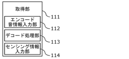
- FIG. 3 is a block diagram showing the functional configuration of the acquisition unit according to the embodiment. As shown in FIG. 3, the acquisition unit 111 in this embodiment includes, for example, an encoded sound information input unit 112, a decode processing unit 113, and a sensing information input unit 114.
- the encoded sound information input unit 112 is a processing unit to which the encoded (in other words, encoded) sound information acquired by the acquisition unit 111 is input.
- the encoded sound information includes a sound signal encoded in a predetermined format, such as MPEG-H 3D Audio (ISO/IEC 23008-3).
- the encoded sound information input unit 112 outputs the input sound information to the decoding processing unit 113.
- the decoding processing unit 113 is a processing unit that decodes (in other words, decodes) the sound information output from the encoded sound information input unit 112 to generate a reproduced sound (sound signal), the position of the sound source object, and a flag, contained in the sound information, in a format used for subsequent processing.
- the sensing information input unit 114 will be described below, along with the functions of the detector 103.
- the processing performed by the encoded sound information input unit 112 and the decoding processing unit 113 may be executed by a device external to the information processing device 101.
- the acquisition unit 111 only needs to acquire sound information, and may acquire sound information that has been decoded by an external device via the communication module 102.
- sound information does not have to be encoded.
- information on the reproduced sound may be acquired as an unencoded sound signal such as a PCM signal.
- the sound signal and spatial information contained in the sound information may be acquired in separate streams or files, or may be acquired in the same stream or file.
- the acquisition unit 111 may also include a head-related transfer function input unit (not shown), and may acquire a set of head-related transfer functions acquired from the outside via the communication module 102, and output the set to the memory unit 105.
- a head-related transfer function input unit (not shown)
- the acquisition unit 111 may also include a head-related transfer function input unit (not shown), and may acquire a set of head-related transfer functions acquired from the outside via the communication module 102, and output the set to the memory unit 105.
- the detector 103 is a device for detecting the speed of movement of the user 99's head.
- the detector 103 is configured by combining various sensors used for detecting movement, such as a gyro sensor and an acceleration sensor.
- the detector 103 is built into the sound reproduction system 100, but it may also be built into an external device, such as a 3D image reproduction device 300 that operates in response to the movement of the user 99's head in the same way as the sound reproduction system 100. In this case, the detector 103 does not need to be included in the sound reproduction system 100.
- the detector 103 may detect the movement of the user 99 by capturing an image of the head movement of the user 99 using an external imaging device or the like and processing the captured image.
- the detector 103 is, for example, fixed integrally to the housing of the sound reproduction system 100 and detects the speed of movement of the housing. After the sound reproduction system 100 including the housing is worn by the user 99, it moves integrally with the head of the user 99, and as a result, the detector 103 can detect the speed of movement of the head of the user 99.
- the detector 103 may detect, for example, the amount of movement of the user 99's head as the amount of rotation about at least one of three mutually orthogonal axes in three-dimensional space as the rotation axis, or may detect the amount of displacement about at least one of the above three axes as the displacement direction. Furthermore, the detector 103 may detect both the amount of rotation and the amount of displacement as the amount of movement of the user 99's head.
- the sensing information input unit 114 acquires the speed of movement of the head of the user 99 from the detector 103. More specifically, the sensing information input unit 114 acquires the amount of head movement of the user 99 detected by the detector 103 per unit time as the speed of movement. In this way, the sensing information input unit 114 acquires at least one of the rotation speed and the displacement speed from the detector 103. The amount of head movement of the user 99 acquired here is used to determine the position and posture (in other words, coordinates and orientation) of the user 99 in the three-dimensional sound field. Therefore, the acquisition unit 111 also functions as a position acquisition unit by the sensing information input unit 114.
- the relative position of the sound image object with respect to the user 99 is determined based on the determined coordinates and orientation of the user 99, and sound is reproduced. Specifically, the above functions are realized by the path calculation unit 121 and the output sound generation unit 131.
- the path calculation unit 121 includes an arrival direction calculation function that calculates the relative arrival direction of the reproduced sound from the position of the sound source object to the position of the user 99 based on the determined coordinates and orientation of the user 99, and a synthetic sound calculation function that calculates a propagation path from the sound source object and calculates a synthetic sound that arrives at the position of the user 99 by indirect propagation of the reproduced sound according to the calculated propagation path of the reproduced sound, and the arrival direction of the synthetic sound.
- the path calculation unit 121 is also an example of an arrival direction calculation unit.
- the path calculation unit 121 may be realized by any process as long as it can calculate the direction of arrival of the reproduced sound when it reaches the user as direct sound, and can calculate the direction of arrival of a synthesized sound (e.g., a reflected sound, a diffracted sound, a reverberant sound, etc.) that arrives at the position of the user 99 by indirect propagation of the reproduced sound.
- the path calculation unit 121 determines from which direction in the three-dimensional sound field the reproduced sound and the synthesized sound are to be perceived by the user 99 as coming from, based on the coordinates and orientation of the user 99, and processes the sound information so that the sound is perceived as such when the output sound signal is reproduced.
- the output sound generating unit 131 is a processing unit that generates an output sound signal by processing information about the reproduced sound contained in the sound information.
- FIG. 4 is a block diagram showing the functional configuration of the output sound generation unit according to the embodiment.
- the output sound generation unit 131 in the present embodiment includes, for example, a switching unit 132, a first generation unit 133, and a second generation unit 134.
- the switching unit 132 is a processing unit for switching whether to use the first generation unit 133 or the second generation unit 134 when generating an output sound signal. Therefore, the switching unit 132 has a function of acquiring information for determining whether to use the first generation unit 133 or the second generation unit 134.
- the first generation unit 133 is a processing unit used when the head-related transfer function is directly convolved with the reproduced sound without applying panning processing.
- the first generation unit 133 is a processing unit used when generating an output sound signal in so-called "normal mode".
- the first generation unit 133 acquires the reproduced sound and the head-related transfer function corresponding to the direction from which the reproduced sound comes, and performs convolution processing of the acquired head-related transfer function with the reproduced sound to generate an output sound signal.
- the second generation unit 134 is a processing unit used when performing conversion processing to convert the reproduced sound into a representative sound by applying a panning process, and then convolving a head-related transfer function with the converted representative sound.
- the second generation unit 134 is a processing unit used when generating an output sound signal in a so-called "low processing mode".
- the second generation unit 134 acquires the reproduced sound and the position of the representative point, and performs conversion processing into a representative sound in order to reproduce the reproduced sound by sound from the representative point.
- the representative sound can be generated by adjusting the gain of the generated sound so that it matches the position of the sound source object.
- the conversion from the playback sound to the representative sound is not limited to this example.
- the playback sound may be converted to the representative sound by performing a time shift adjustment and a gain adjustment as described later, or any other existing conversion may be used as long as the playback sound can be converted to a representative sound for reproducing the sound from the representative point.
- An example of the conversion that performs the time shift adjustment and the gain adjustment will be described later.
- the second generation unit 134 acquires representative sounds equal to the number of representative points obtained by the conversion and head related transfer functions corresponding to the representative direction from each representative point to the position of the user 99, and performs a convolution process of the acquired head related transfer functions on the representative sound to generate an output sound signal.
- the output sound generating unit 131 acquires the head-related transfer function used for generating the output sound signal from the storage unit 105.
- the storage unit 105 is an information storage device that has both a function as a storage device for storing information and a function as a storage controller that reads out the stored information and outputs it to other processing units included in the information processing device.
- the storage unit 105 may be read as a memory provided in the information processing device 101.
- the storage unit 105 stores the head-related transfer function acquired by the acquisition unit 111 for each direction of arrival to the user 99.
- the head-related transfer function included in the storage unit 105 is a set of general-purpose head-related transfer functions that can be used by everyone, or a set of head-related transfer functions optimized for the individual user 99, or a set of head-related transfer functions that are publicly available.
- the storage unit 105 receives an inquiry from the output sound generating unit 131 with the direction of arrival as a query, and outputs the head-related transfer function corresponding to the direction of arrival to the output sound generating unit 131. Furthermore, in response to an inquiry from the switching unit 132, the output sound generating unit 131 may output the entire set of head-related transfer functions, or may output the characteristics of the set of head-related transfer functions itself.
- the set of head-related transfer functions may be acquired from the outside by the acquiring unit 111, for example, in the form of a SOFA file, and then stored in the storage unit 105.
- the signal output unit 141 is a functional unit that outputs the generated output sound signal to the driver 104.
- the signal output unit 141 generates a waveform signal by performing signal conversion from a digital signal to an analog signal based on the output sound signal, and generates sound waves in the driver 104 based on the waveform signal, presenting the sound to the user 99.
- the driver 104 has, for example, a diaphragm and a driving mechanism such as a magnet and a voice coil.
- the driver 104 operates the driving mechanism according to the waveform signal, and vibrates the diaphragm using the driving mechanism.
- the driver 104 generates sound waves by the vibration of the diaphragm according to the output sound signal (meaning that the output sound signal is "reproduced”; in other words, the meaning of "reproduction” does not include the perception by the user 99), and the sound waves propagate through the air and are transmitted to the ears of the user 99, and the user 99 perceives the sound.
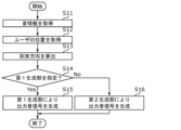
- FIG. 5 is a flowchart showing a first operation example of the information processing device according to the embodiment.
- the acquisition unit 111 acquires sound information via the communication module 102 (step S11).
- the sound information is decoded by the decoding processing unit 113 into information about the reproduced sound, information about the position of the sound source object, and a flag, and generation of an output sound signal is started.
- the sensing information input unit 114 acquires information about the position of the user 99 (step S12).
- the path calculation unit 121 calculates the arrival direction of the reproduced sound based on the position of the sound source object and the position of the user 99 (step S13).
- the flag included in the sound information is a flag added by the creator when the sound information is created. This flag is a flag for specifying whether the output sound signal is to be generated by the first generation unit 133 or the second generation unit 134. Since the creator knows what sound source objects are included in the original sound information, it is possible to add a flag that causes the output sound signal to be generated by the first generation unit 133, for example, because the number of sound source objects included in the sound information is quite small.
- the creator can add a flag to cause the second generation unit 134 to generate an output sound signal because, for example, the sound information contains a large number of sound source objects. If the flag specifies that an output sound signal is to be generated by the first generation unit 133, it may be treated as equivalent to a flag specifying that an output sound signal is not to be generated by the second generation unit 134. Also, if the flag specifies that an output sound signal is to be generated by the second generation unit 134, it may be treated as equivalent to a flag specifying that an output sound signal is not to be generated by the first generation unit 133.
- the output sound generation unit 131 may use the switching unit 132 to make the determination in step S14 and to switch between generating an output sound signal using the first generation unit 133 or generating an output sound signal using the second generation unit 134, or a flag determination unit (not shown) may make the determination in step S14, and depending on the determination result, the acquisition unit 111 may directly input sound information to the first generation unit 133 or input sound information to the second generation unit 134. In other words, it is not necessary to switch between generating an output sound signal using the first generation unit 133 and generating an output sound signal using the second generation unit 134.
- FIG. 6 is a flowchart showing a second operation example of the information processing device according to the embodiment.
- the operation example shown in FIG. 6 is similar to that of FIG. 5 except that step S24 is executed instead of step S14, and therefore description thereof will be omitted.
- the process switches between executing step S15 or step S16. Specifically, the switching unit 132 acquires the sound information and counts the number of sound source objects.
- the switching unit 132 also acquires the number of representative points set in the three-dimensional sound field (the number of representative points is stored as setting information in a storage unit, not shown, or the like). The switching unit 132 then compares the number of sound source objects with the number of representative points. The switching unit 132 determines whether the comparison result satisfies a predetermined condition, for example, based on whether the number of sound source objects is less than a coefficient multiple of the number of representative points as a predetermined condition (step S24). If the predetermined condition is satisfied (the number of sound source objects is less than a coefficient multiple of the number of representative points) (Yes in S24), the switching unit 132 switches to execute step S15.
- a predetermined condition for example, based on whether the number of sound source objects is less than a coefficient multiple of the number of representative points as a predetermined condition (step S24). If the predetermined condition is satisfied (the number of sound source objects is less than a coefficient multiple of the number of representative points) (Yes in S24), the switching unit 132
- the switching unit 132 switches to execute step S16.
- the coefficient multiple is set assuming that the generation of an output sound signal in the normal mode is equivalent to or more advantageous than the generation of an output sound signal in the low processing mode in terms of the amount of processing.
- the panning process has its own processing amount, so the coefficient varies within a range from a few times, such as 1x, 3x, or 5x, to several tens of times, such as 10x, 30x, or 50x, depending on the panning process implemented. In other words, the coefficient can be set to an appropriate value depending on the type of panning process.
- an output sound signal is generated for the reproduced sound, it may sound unnatural, so in this embodiment, the reproduced sound that arrives by indirect propagation is generated as a synthetic sound.
- a synthetic sound also needs to be perceived as a sound from the appropriate direction of arrival, and needs to be included in the output sound signal in the same way as the reproduced sound from the sound source object.
- FIG. 8 is a flowchart showing a third operation example of the information processing device according to the embodiment.
- the operation example shown in FIG. 8 is the same as FIG. 5 except that step S34 is executed instead of step S14, and therefore description thereof is omitted.
- step S13 whether to execute step S15 or step S16 is switched depending on whether the head-related transfer functions contained in the storage unit 105 are dense enough to fully exert the effect of reducing the amount of processing by applying the panning process.
- the switching unit 132 queries the storage unit 105 and reads out a set of head-related transfer functions or reads out characteristic information related to the density of the head-related transfer functions. Then, the switching unit 132 determines whether the head-related transfer functions contained in the storage unit 105 are sparser or denser than a preset threshold value.
- the switching unit 132 determines whether the characteristic related to the sparseness of the head related transfer function is denser than the threshold related to the sparseness and density and thus satisfies a predetermined condition (step S34). If the predetermined condition is not satisfied (the characteristic related to the sparseness and density of the head related transfer function is sparser than the threshold) (Yes in S34), the switching unit 132 switches to execute step S15. If the predetermined condition is satisfied (the characteristic related to the sparseness and density of the head related transfer function is denser than the threshold) (No in S34), the switching unit 132 switches to execute step S16.
- the threshold related to the sparseness and density is set, for example, depending on whether the head related transfer function is included at a density denser than the step angle in at least one direction, such as 5 degrees, 10 degrees, and 15 degrees in the horizontal direction and 5 degrees, 10 degrees, and 15 degrees in the vertical direction.
- the threshold related to the sparseness and density also depends on the direction of arrival of the reproduced sound from the sound source object included in the sound information, and also on the representative direction from the set representative point. Therefore, it should be set appropriately according to the arrival direction of the reproduced sound from the sound source object contained in the sound information and the representative direction from the representative point.
- the reproduced sounds from a plurality of sound source objects are expressed by representative sounds from a plurality of representative directions.
- two to three directions can be used as the representative directions.
- the number of representative points is less than the number of sound source objects, and the reproduced sounds can be perceived as sounds from the arrival direction only by the head transfer functions of the representative directions for the representative points.
- the panning process may be interpreted as a process of distributing the reproduced sounds to the representative points (representative directions). Specifically, the sound signals of the reproduced sounds associated with the positions of the respective sound source objects are distributed to the positions of the representative points, and representative sounds arriving from the representative points (representative directions) to the listener are generated.
- the representative direction is a direction determined by the relationship between the head direction of the listener and the position of the representative point. For example, it refers to the direction of the representative point as seen from the front of the listener. It may also be rephrased as the direction of the representative point when the direction in which the listener's face is facing is used as a reference, or the direction of the representative point as seen from the listener's eyes.
- the panning process calculates the time shift (delay) that maximizes the cross-correlation between the head-related transfer function in the direction of arrival from the sound source object and the head-related transfer function in the representative direction.
- the time shift obtained here or a time shift with a negative sign added to this time shift, is applied to the sound played back from the sound source object, and the subsequent processing is performed assuming that the signal after the time shift is in the representative direction.
- This time shift may also be permitted to be a time shift shorter than the sampling period (a shift in which the sample position is expressed as a decimal; hereafter referred to as a "decimal shift").
- This decimal shift can be performed by oversampling.
- a gain is applied to the signal of the representative direction obtained by time-shifting the sound reproduced from the sound source object, and the sum of the signals calculated for each representative point is calculated by convolving the head-related transfer function at each representative point, thereby synthesizing a signal equivalent to the sound reproduced from the sound source object convolved with the head-related transfer function of the arrival direction.
- the gain may be calculated by making the error signal vector between the synthesized head-related transfer function (vector) and the head-related transfer function (vector) of the direction of arrival orthogonal to the head-related transfer function (vector) of the representative direction.
- a head-related transfer function (vector) is a time waveform of the head impulse response, which is an expression of the head-related transfer function in the time domain, considered as a vector.
- this head-related transfer function (vector) will also be referred to simply as a "head-related transfer function vector".
- this gain is corrected so that the energy balance of the head-related transfer functions from the position of the sound source object to the left and right ears of the user 99 is maintained in the head-related transfer function synthesized by the panning process from the head-related transfer functions from multiple representative points.
- the gain may be corrected so that the energy balance of the head-related transfer functions of the left and right ears of the user 99 due to the sound source object is maintained in the head-related transfer function synthesized by the panning process.
- the panning process calculates a gain value to be multiplied with the head-related transfer function of the representative direction and a time shift value to be applied to the head-related transfer function of the representative direction for each direction from which the sound source object comes, and stores these in table data (head-related transfer function table or adjustment amount table) described below.
- each sound source object is time shifted by a time shift value and gain value corresponding to the direction from which each sound source object arrives, a gain is applied, and the sum of these is taken to generate a sum signal.
- this sum signal is treated as being present at the position of the representative point.
- the head-related transfer function in the direction of the representative point is convolved with this sum signal to generate a signal at the ear of the user 99.
- the panning process may use a gain calculated to minimize the energy or L2 norm of the error signal vector between the synthesized HRIR vector and the HRIR vector in the sound source direction.
- the HRIR vector is a vector whose elements are values obtained by sampling the time domain waveform of the head related transfer function at a sampling frequency of 48 kHz.
- the time shift and/or gain may be calculated by applying a weighting filter on the frequency axis.
- frequency weighting filter when calculating the time shift and gain that maximize the cross-correlation, it is possible to use a frequency-axis weighting filter (hereinafter also referred to as a "frequency weighting filter").
- This frequency weighting filter should preferably have a cutoff frequency near or slightly higher than the frequency band where human hearing sensitivity is high, and attenuate the higher bands, i.e., the bands where human hearing sensitivity decreases.
- a low pass filter LPF
- the adjustment amounts in the time shift adjustment and the gain adjustment may be determined according to the set of head-related transfer functions included in the storage unit 105, and the time shift adjustment and the gain adjustment may be applied to the playback sound with the determined adjustment amount to convert it into a representative sound.
- the adjustment amounts in the time shift adjustment and the gain adjustment used in the panning process change according to the head-related transfer function, first, when a set of head-related transfer functions such as a SOFA file is acquired, or when a set of head-related transfer functions included in the storage unit 105 is read, the adjustment amounts in the time shift adjustment and the gain adjustment corresponding to each head-related transfer function included in the set of head-related transfer functions are determined, and the same adjustment amounts can be reused as long as this set of head-related transfer functions is used thereafter, which is advantageous in terms of the amount of processing.
- a set of head-related transfer functions such as a SOFA file is acquired, or when a set of head-related transfer functions included in the storage unit 105 is read
- the adjustment amounts in the time shift adjustment and the gain adjustment corresponding to each head-related transfer function included in the set of head-related transfer functions are determined, and the same adjustment amounts can be reused as long as this set of head-related transfer functions is used thereafter, which is advantageous in terms of the amount of processing.
- the panning process when, for example, three representative directions are used in the panning process, first, when a set of head-related transfer functions is acquired (for example, at the time of initialization), multiple representative direction candidates (for example, eight directions) are selected from the directions of the celestial sphere included in the set of head-related transfer functions. Next, for each of the celestial sphere head-related transfer functions included in the set of head-related transfer functions, it is determined which three directions among the multiple representative direction candidates are to be used as the representative direction. Next, for each of the celestial sphere directions included in the set of head-related transfer functions, adjustment amounts in time shift adjustment and gain adjustment for distributing signals to the identified three representative directions are calculated. Then, the calculated adjustment amounts are determined as the adjustment amounts associated with each of the celestial sphere directions included in the set of head-related transfer functions.
- the head-related transfer function table is an example of table data including head-related transfer functions stored in the storage unit 105.
- the head-related transfer functions are stored together with the adjustment amounts in the time shift adjustment and gain adjustment determined according to the head-related transfer functions, which are linked to each other.
- the head-related transfer function table may be constructed by calculating the adjustment amounts in the time shift adjustment and gain adjustment in advance for each head-related transfer function included in the storage unit 105.
- table data of the head-related transfer function table linking each head-related transfer function with the adjustment amount may be stored in the storage unit 105.
- the calculation of the adjustment amount for each head-related transfer function may be performed by the second generation unit 134 or the decode processing unit 113.
- the adjustment amount may be calculated by an external device and stored in the memory of the external device. In this case, the memory of the external device corresponds to an example of a storage unit.
- the adjustment amount in the time shift adjustment and the gain adjustment may be calculated in advance for each direction of the multiple head-related transfer functions included in the set of head-related transfer functions, and an adjustment amount table linking each of the multiple representative directions with the adjustment amount for each direction of the multiple head-related transfer functions included in the set of head-related transfer functions may be constructed and stored in the storage unit 105.
- the multiple representative directions are representative directions (e.g., three directions) selected from multiple representative direction candidates (e.g., eight directions)
- the adjustment amount table includes information on which representative direction (e.g., three directions) was selected from the multiple representative direction candidates (e.g., eight directions) for each direction of the celestial sphere included in the set of head-related transfer functions.
- the adjustment amount table may include table data linking the head-related transfer functions of each of the multiple representative directions with the adjustment amount in the time shift adjustment and the gain adjustment for each direction of the multiple head-related transfer functions included in the set of head-related transfer functions, or the head-related transfer functions of each of the multiple representative directions may be extracted at the time of rendering or at the time of system initialization from a set of head-related transfer functions of the celestial sphere (multiple directions) previously acquired and stored in the storage unit 105. Also, a set of head-related transfer functions may be obtained from outside when the system is initialized, and an adjustment amount table may be constructed at the time of initialization and then stored in the storage unit 105. In this case, the adjustment amount table stored in the storage unit 105 may be read out and used when processing the output of the audio signal.
- the process of updating spatial information (information update thread) and the process of outputting an audio signal with added acoustic processing (audio thread) may be executed in a single thread, or in different threads.
- the thread startup frequency may be set individually, or the processes may be executed in parallel.
- the allocation of computational resources to the spatial information update process is limited.
- updating of spatial information is a low-frequency process compared to the audio signal output process (for example, a process such as updating the direction of the listener's face)
- it does not necessarily have to be performed in near real time with no delay, as is the case with the audio signal output process. Therefore, even if the allocation of computational resources is limited, it does not have a significant impact on acoustic quality.
- the spatial information may be updated periodically at preset times or intervals, or when preset conditions are met.
- the spatial information may also be updated manually by the listener or the sound space manager, or may be updated in response to a change in an external system.
- spatial information may be updated when a listener operates a controller to instantly warp the position of the listener's own avatar or to instantly advance or reverse the time.
- spatial information may be updated when an administrator of the virtual space suddenly changes the environment of the place.
- the thread for updating spatial information may be started as a one-off interrupt process in addition to being started periodically.
- the spatial information update process may be performed when the virtual space is created (when the software is created), when virtual space information (scene information) is loaded, when virtual space processing begins (when the software is launched or rendering begins), or when an information update thread occurs that occurs periodically in virtual space processing.
- the virtual space may be created when the virtual space is constructed before the start of acoustic processing, when virtual space information (spatial information) is acquired, or when the software is acquired.
- processing threads in other words, workflows
- a processing thread that occurs irregularly a processing thread that occurs infrequently and periodically, such as updating the listener's facial direction
- a processing thread that occurs frequently and periodically such as sound output processing.
- the processing at initialization in the present disclosure corresponds to the irregular processing thread of the above.
- the adjustment amount table may also be a table that includes, for example, information on which of a plurality of representative directions to distribute a sound signal arriving at the listener's position from the direction of each head-related transfer function of the set of omnidirectional head-related transfer functions, and information on the time shift adjustment amount and gain adjustment amount to be multiplied by the sound signal for each representative direction when distributing the signal.
- the adjustment amount table stored in the memory unit 105 is referenced, and the adjustment amounts for the time shift adjustment and gain adjustment linked to the head-related transfer function of the direction to be applied are used, which eliminates the need to calculate the adjustment amount for each convolution process and contributes to reducing the amount of processing.
- the embodiment of the present invention can also be applied to a new set of head-related transfer functions (e.g., a SOFA file) that is not included in the storage unit 105.
- a new set of head-related transfer functions e.g., a SOFA file
- the head-related transfer functions of the entire three-dimensional sound field may be newly read, the representative direction may be determined again using the method disclosed in this embodiment or another method, and the adjustment amount for each head-related transfer function included in the new set of head-related transfer functions may be calculated.
- table data linking the head-related transfer functions and the adjustment amount may be stored in the storage unit 105.
- the adjustment amount may be calculated by an external device and stored in the memory of the external device.
- the adjustment amounts in the time shift adjustment and gain adjustment used in the panning process may be determined for the new set of head-related transfer functions before storing them in the storage unit 105, and a head-related transfer function table may be constructed by linking the new set of head-related transfer functions with the determined adjustment amounts, and the head-related transfer function table may be stored in the storage unit 105. Then, when performing the panning process, these adjustment amounts are read from the storage unit 105, and the shift adjustment and gain adjustment are applied according to the adjustment amounts.
- the new head-related transfer functions may be ones that were previously stored in the storage unit 105, but were temporarily removed from the storage unit 105 when decoding the sound signal, when the sound reproduction system 100 is turned on, or when the sound reproduction system 100 is initialized, and then stored again in the storage unit 105.
- the table data for a new set of head-related transfer functions and the table data previously stored in the storage unit 105 may be stored in the storage unit 105 as table data corresponding to a different set of head-related transfer functions.
- the table data stored in the storage unit 105 here may be a head-related transfer function table or an adjustment amount table that is a part of the head-related transfer function table.
- a determination of the adjustment amount is effective without switching whether or not to perform panning processing. That is, a third generation unit different from the first generation unit 133 and the second generation unit 134 may be provided instead of the first generation unit 133 and the second generation unit 134, which applies time shift adjustment and gain adjustment to the playback sound with the adjustment amount linked to the new head-related transfer function stored in the storage unit 105 to convert it into a representative sound, and generates an output sound signal by convolving the head-related transfer function corresponding to the representative direction from each position of the representative point toward the user's position into the representative sound.
- the sound reproduction system described in the above embodiment may be realized as a single device having all the components, or may be realized by allocating each function to a plurality of devices and coordinating these devices.
- an information processing device such as a smartphone, a tablet terminal, or a PC may be used as the device corresponding to the information processing device.
- a server may perform all or part of the renderer's functions. That is, all or part of the acquisition unit 111, the path calculation unit 121, the output sound generation unit 131, and the signal output unit 141 may be present in a server (not shown).
- the sound reproduction system 100 is realized by combining, for example, an information processing device such as a computer or a smartphone, a sound presentation device such as a head mounted display (HMD) or earphones worn by the user 99, and a server (not shown).
- the computer, the sound presentation device, and the server may be connected to each other so as to be able to communicate with each other via the same network, or may be connected via different networks. If they are connected via different networks, there is a high possibility that communication delays will occur, so processing on the server may be permitted only when the computer, sound presentation device, and server are connected to be able to communicate via the same network. Also, depending on the amount of bitstream data accepted by the sound reproduction system 100, it may be determined whether the server will take on all or part of the functions of the renderer.
- the audio reproduction system of the present disclosure can also be realized as an information processing device that is connected to a reproduction device equipped with only a driver and that only reproduces an output sound signal generated based on acquired sound information for the reproduction device.
- the information processing device may be realized as hardware equipped with a dedicated circuit, or as software that causes a general-purpose processor to execute specific processing.
- processing performed by a specific processing unit may be executed by another processing unit.
- the order of multiple processes may be changed, and multiple processes may be executed in parallel.
- each component may be realized by executing a software program suitable for each component.
- Each component may be realized by a program execution unit such as a CPU or processor reading and executing a software program recorded on a recording medium such as a hard disk or semiconductor memory.
- each component may be realized by hardware.
- each component may be a circuit (or an integrated circuit). These circuits may form a single circuit as a whole, or each may be a separate circuit. Furthermore, each of these circuits may be a general-purpose circuit, or a dedicated circuit.
- the general or specific aspects of the present disclosure may be realized in an apparatus, a device, a method, an integrated circuit, a computer program, or a recording medium such as a computer-readable CD-ROM.
- the general or specific aspects of the present disclosure may be realized in any combination of an apparatus, a device, a method, an integrated circuit, a computer program, and a recording medium.
- the present disclosure may be realized as an audio signal reproducing method executed by a computer, or as a program for causing a computer to execute the audio signal reproducing method.
- the present disclosure may be realized as a computer-readable non-transitory recording medium on which such a program is recorded.
- this disclosure also includes forms obtained by applying various modifications to each embodiment that a person skilled in the art may conceive, or forms realized by arbitrarily combining the components and functions of each embodiment within the scope of the spirit of this disclosure.
- the encoded sound information in this disclosure can be rephrased as a bitstream including a sound signal, which is information about a specific sound reproduced by the sound reproduction system 100, and metadata, which is information about a localization position when a sound image of the specific sound is localized at a specific position in a three-dimensional sound field.
- the sound information may be acquired by the sound reproduction system 100 as a bitstream encoded in a specific format such as MPEG-H 3D Audio (ISO/IEC 23008-3).
- the encoded sound signal includes information about a specific sound reproduced by the sound reproduction system 100.
- the specific sound here is a sound emitted by a sound source object existing in the three-dimensional sound field or a natural environmental sound, and may include, for example, a mechanical sound or the voice of an animal including a human.
- the sound reproduction system 100 will acquire multiple sound signals corresponding to the multiple sound source objects.
- Metadata is, for example, information used to control the acoustic processing of a sound signal in the sound reproduction system 100.
- the metadata may be information used to describe a scene expressed in a virtual space (three-dimensional sound field).
- a scene is a term that refers to a collection of all elements that represent three-dimensional images and acoustic events in a virtual space, which are modeled in the sound reproduction system 100 using metadata.
- the metadata here may include not only information that controls the acoustic processing, but also information that controls the video processing.
- the metadata may include information that controls only one of the audio processing and the video processing, or may include information used to control both.
- the bitstream acquired by the sound reproduction system 100 may include such metadata.
- the sound reproduction system 100 may acquire the metadata separately, separately from the bitstream, as described below.
- the sound reproduction system 100 generates virtual sound effects by performing sound processing on the sound signal using metadata included in the bitstream and additionally acquired position information of the interactive user 99.
- sound effects such as early reflection sound generation, late reverberation sound generation, diffraction sound generation, distance attenuation effect, localization, sound image localization processing, or Doppler effect may be added.
- Information for switching all or part of the sound effects on and off may also be added as metadata.
- the audio reproduction system 100 may have a function for outputting metadata that can be used for controlling the video to a display device that displays images or a 3D video reproduction device that reproduces 3D video.
- the encoded metadata includes information about a three-dimensional sound field including a sound source object that emits a sound and an obstacle object, and information about a position when the sound image of the sound is localized at a predetermined position in the three-dimensional sound field (i.e., the sound is perceived as arriving from a predetermined direction), i.e., information about the predetermined direction.
- an obstacle object is an object that can affect the sound perceived by the user 99, for example, by blocking or reflecting the sound emitted by the sound source object until it reaches the user 99.
- obstacle objects can include animals such as people, or moving objects such as machines.
- the other sound source objects can be obstacle objects for any sound source object.
- both non-sound source objects such as building materials or inanimate objects and sound source objects that emit sounds can be obstacle objects.
- reflectance was mentioned as a parameter related to an obstacle object or sound source object included in the metadata, but the metadata may also include information other than reflectance.
- metadata related to both sound source objects and non-sound source objects may include information related to the material of the object.
- the metadata may include parameters such as diffusion rate, transmittance, or sound absorption rate.
- Information about the sound source object may include volume, radiation characteristics (directivity), playback conditions, the number and type of sound sources emitted from one object, or information specifying the sound source area in the object.
- the playback conditions may determine, for example, whether the sound is a sound that continues to play continuously or a sound that triggers an event.
- the sound source area in the object may be determined in a relative relationship between the position of the user 99 and the position of the object, or may be determined based on the object.
- the surface on which the user 99 is looking at the object is used as the reference, and the user 99 can be made to perceive that sound X is coming from the right side of the object and sound Y is coming from the left side as seen by the user 99.
- it is determined based on the object it is possible to fix which sound is coming from which area of the object, regardless of the direction in which the user 99 is looking.
- the user 99 can be made to perceive that a high-pitched sound is coming from the right side and a low-pitched sound is coming from the left side when the object is viewed from the front.
- the user 99 goes around to the back of the object, the user 99 can be made to perceive that a low-pitched sound is coming from the right side and a high-pitched sound is coming from the left side when viewed from the back.
- Spatial metadata can include the time to early reflections, reverberation time, or the ratio of direct sound to diffuse sound. If the ratio of direct sound to diffuse sound is zero, the user 99 will only perceive direct sound.
- information indicating the position and orientation of the user 99 in the three-dimensional sound field may be included in the bitstream as metadata in advance as an initial setting, or may not be included in the bitstream. If the information indicating the position and orientation of the user 99 is not included in the bitstream, the information indicating the position and orientation of the user 99 is obtained from information other than the bitstream.
- the position information of the user 99 in the VR space may be obtained from an app that provides VR content
- the position information of the user 99 for presenting sound as AR may be obtained by using, for example, position information obtained by a mobile terminal performing self-position estimation using a GPS, a camera, or LiDAR (Laser Imaging Detection and Ranging).
- the sound signal and metadata may be stored in one bitstream or may be stored separately in multiple bitstreams.
- the sound signal and metadata may be stored in one file or may be stored separately in multiple files.
- information indicating other related bitstreams may be included in one or some of the multiple bitstreams in which the audio signal and metadata are stored. Also, information indicating other related bitstreams may be included in the metadata or control information of each bitstream of the multiple bitstreams in which the audio signal and metadata are stored.
- information indicating other related bitstreams or files may be included in one or some of the multiple files in which the audio signal and metadata are stored. Also, information indicating other related bitstreams or files may be included in the metadata or control information of each bitstream of the multiple bitstreams in which the audio signal and metadata are stored.
- the related bitstreams or files are, for example, bitstreams or files that may be used simultaneously during audio processing.
- information indicating other related bitstreams may be described collectively in the metadata or control information of one bitstream among the multiple bitstreams storing audio signals and metadata, or may be described separately in the metadata or control information of two or more bitstreams among the multiple bitstreams storing audio signals and metadata.
- information indicating other related bitstreams or files may be described collectively in the metadata or control information of one file among the multiple files storing audio signals and metadata, or may be described separately in the metadata or control information of two or more files among the multiple files storing audio signals and metadata.
- a control file in which information indicating other related bitstreams or files is described collectively may be generated separately from the multiple files storing audio signals and metadata. In this case, the control file does not have to store audio signals and metadata.
- the information indicating the other related bitstream or file may be, for example, an identifier indicating the other bitstream, a file name indicating the other file, a URL (Uniform Resource Locator), or a URI (Uniform Resource Identifier).
- the acquisition unit 111 identifies or acquires the bitstream or file based on the information indicating the other related bitstream or file.
- the information indicating the other related bitstream may be included in the metadata or control information of at least some of the bitstreams among the multiple bitstreams storing the sound signal and metadata
- the information indicating the other related file may be included in the metadata or control information of at least some of the files among the multiple files storing the sound signal and metadata.
- the file including the information indicating the related bitstream or file may be, for example, a control file such as a manifest file used for content distribution.
- This disclosure is useful when reproducing sound, such as allowing a user to perceive three-dimensional sound.
Landscapes
- Engineering & Computer Science (AREA)
- Physics & Mathematics (AREA)
- Acoustics & Sound (AREA)
- Signal Processing (AREA)
- Multimedia (AREA)
- Stereophonic System (AREA)
Priority Applications (7)
| Application Number | Priority Date | Filing Date | Title |
|---|---|---|---|
| JP2025514020A JPWO2024214799A1 (https=) | 2023-04-14 | 2024-04-11 | |
| KR1020257032057A KR20260002628A (ko) | 2023-04-14 | 2024-04-11 | 정보 처리 장치, 정보 처리 방법, 및, 프로그램 |
| AU2024250844A AU2024250844A1 (en) | 2023-04-14 | 2024-04-11 | Information processing device, information processing method, and program |
| EP24788821.7A EP4697758A1 (en) | 2023-04-14 | 2024-04-11 | Information processing device, information processing method, and program |
| CN202480024063.2A CN120917773A (zh) | 2023-04-14 | 2024-04-11 | 信息处理装置、信息处理方法以及程序 |
| MX2025011434A MX2025011434A (es) | 2023-04-14 | 2025-09-26 | Dispositivo de procesamiento de informacion, metodo de procesamiento de informacion, y programa |
| US19/347,121 US20260032401A1 (en) | 2023-04-14 | 2025-10-01 | Information processing device, information processing method, and recording medium |
Applications Claiming Priority (2)
| Application Number | Priority Date | Filing Date | Title |
|---|---|---|---|
| JP2023-066552 | 2023-04-14 | ||
| JP2023066552 | 2023-04-14 |
Related Child Applications (1)
| Application Number | Title | Priority Date | Filing Date |
|---|---|---|---|
| US19/347,121 Continuation US20260032401A1 (en) | 2023-04-14 | 2025-10-01 | Information processing device, information processing method, and recording medium |
Publications (1)
| Publication Number | Publication Date |
|---|---|
| WO2024214799A1 true WO2024214799A1 (ja) | 2024-10-17 |
Family
ID=93059644
Family Applications (1)
| Application Number | Title | Priority Date | Filing Date |
|---|---|---|---|
| PCT/JP2024/014744 Ceased WO2024214799A1 (ja) | 2023-04-14 | 2024-04-11 | 情報処理装置、情報処理方法、及び、プログラム |
Country Status (9)
| Country | Link |
|---|---|
| US (1) | US20260032401A1 (https=) |
| EP (1) | EP4697758A1 (https=) |
| JP (1) | JPWO2024214799A1 (https=) |
| KR (1) | KR20260002628A (https=) |
| CN (1) | CN120917773A (https=) |
| AU (1) | AU2024250844A1 (https=) |
| MX (1) | MX2025011434A (https=) |
| TW (1) | TW202508310A (https=) |
| WO (1) | WO2024214799A1 (https=) |
Citations (3)
| Publication number | Priority date | Publication date | Assignee | Title |
|---|---|---|---|---|
| WO2019116890A1 (ja) * | 2017-12-12 | 2019-06-20 | ソニー株式会社 | 信号処理装置および方法、並びにプログラム |
| JP2020018620A (ja) | 2018-08-01 | 2020-02-06 | 株式会社カプコン | 仮想空間における音声生成プログラム、四分木の生成方法、および音声生成装置 |
| WO2022038929A1 (ja) * | 2020-08-20 | 2022-02-24 | パナソニック インテレクチュアル プロパティ コーポレーション オブ アメリカ | 情報処理方法、プログラム、及び、音響再生装置 |
-
2024
- 2024-04-11 CN CN202480024063.2A patent/CN120917773A/zh active Pending
- 2024-04-11 EP EP24788821.7A patent/EP4697758A1/en active Pending
- 2024-04-11 TW TW113113534A patent/TW202508310A/zh unknown
- 2024-04-11 AU AU2024250844A patent/AU2024250844A1/en active Pending
- 2024-04-11 KR KR1020257032057A patent/KR20260002628A/ko active Pending
- 2024-04-11 WO PCT/JP2024/014744 patent/WO2024214799A1/ja not_active Ceased
- 2024-04-11 JP JP2025514020A patent/JPWO2024214799A1/ja active Pending
-
2025
- 2025-09-26 MX MX2025011434A patent/MX2025011434A/es unknown
- 2025-10-01 US US19/347,121 patent/US20260032401A1/en active Pending
Patent Citations (3)
| Publication number | Priority date | Publication date | Assignee | Title |
|---|---|---|---|---|
| WO2019116890A1 (ja) * | 2017-12-12 | 2019-06-20 | ソニー株式会社 | 信号処理装置および方法、並びにプログラム |
| JP2020018620A (ja) | 2018-08-01 | 2020-02-06 | 株式会社カプコン | 仮想空間における音声生成プログラム、四分木の生成方法、および音声生成装置 |
| WO2022038929A1 (ja) * | 2020-08-20 | 2022-02-24 | パナソニック インテレクチュアル プロパティ コーポレーション オブ アメリカ | 情報処理方法、プログラム、及び、音響再生装置 |
Non-Patent Citations (1)
| Title |
|---|
| See also references of EP4697758A1 |
Also Published As
| Publication number | Publication date |
|---|---|
| TW202508310A (zh) | 2025-02-16 |
| CN120917773A (zh) | 2025-11-07 |
| KR20260002628A (ko) | 2026-01-06 |
| EP4697758A1 (en) | 2026-02-18 |
| JPWO2024214799A1 (https=) | 2024-10-17 |
| AU2024250844A1 (en) | 2025-10-16 |
| US20260032401A1 (en) | 2026-01-29 |
| MX2025011434A (es) | 2025-11-03 |
Similar Documents
| Publication | Publication Date | Title |
|---|---|---|
| JP7715771B2 (ja) | 双方向オーディオ環境のための空間オーディオ | |
| JP7453248B2 (ja) | オーディオ装置およびその処理の方法 | |
| US20250031005A1 (en) | Information processing method, information processing device, acoustic reproduction system, and recording medium | |
| JP7507300B2 (ja) | 低周波数チャネル間コヒーレンス制御 | |
| WO2024214799A1 (ja) | 情報処理装置、情報処理方法、及び、プログラム | |
| CA3288589A1 (en) | Information processing device, information processing method, and program | |
| US20250247667A1 (en) | Acoustic processing method, acoustic processing device, and recording medium | |
| WO2025205328A1 (ja) | 情報処理装置、情報処理方法、及び、プログラム | |
| EP4510631A1 (en) | Acoustic processing device, program, and acoustic processing system | |
| WO2025135070A1 (ja) | 音響情報処理方法、情報処理装置、及び、プログラム | |
| WO2025075102A1 (ja) | 音響処理装置、音響処理方法、及び、プログラム | |
| WO2026018859A1 (ja) | 情報処理方法、情報処理システム、及び、プログラム | |
| WO2025075079A1 (ja) | 音響処理装置、音響処理方法、及び、プログラム | |
| WO2025075082A1 (ja) | 音響処理装置、音響処理方法、及び、プログラム | |
| WO2023199813A1 (ja) | 音響処理方法、プログラム、及び音響処理システム | |
| WO2023199778A1 (ja) | 音響信号処理方法、プログラム、音響信号処理装置、および、音響信号再生システム |
Legal Events
| Date | Code | Title | Description |
|---|---|---|---|
| 121 | Ep: the epo has been informed by wipo that ep was designated in this application |
Ref document number: 24788821 Country of ref document: EP Kind code of ref document: A1 |
|
| WWE | Wipo information: entry into national phase |
Ref document number: KR1020257032057 Country of ref document: KR |
|
| WWE | Wipo information: entry into national phase |
Ref document number: MX/A/2025/011434 Country of ref document: MX |
|
| ENP | Entry into the national phase |
Ref document number: 2025514020 Country of ref document: JP Kind code of ref document: A |
|
| WWE | Wipo information: entry into national phase |
Ref document number: AU2024250844 Country of ref document: AU Ref document number: 2025514020 Country of ref document: JP Ref document number: 202547093420 Country of ref document: IN |
|
| WWE | Wipo information: entry into national phase |
Ref document number: 2501006662 Country of ref document: TH Ref document number: 202480024063.2 Country of ref document: CN |
|
| ENP | Entry into the national phase |
Ref document number: 2024250844 Country of ref document: AU Date of ref document: 20240411 Kind code of ref document: A |
|
| REG | Reference to national code |
Ref country code: BR Ref legal event code: B01A Ref document number: 112025021706 Country of ref document: BR |
|
| WWP | Wipo information: published in national office |
Ref document number: 202547093420 Country of ref document: IN |
|
| WWP | Wipo information: published in national office |
Ref document number: MX/A/2025/011434 Country of ref document: MX |
|
| WWP | Wipo information: published in national office |
Ref document number: 202480024063.2 Country of ref document: CN |
|
| WWE | Wipo information: entry into national phase |
Ref document number: 2024788821 Country of ref document: EP Ref document number: 2025127146 Country of ref document: RU |
|
| NENP | Non-entry into the national phase |
Ref country code: DE |
|
| ENP | Entry into the national phase |
Ref document number: 2024788821 Country of ref document: EP Effective date: 20251114 |
|
| ENP | Entry into the national phase |
Ref document number: 2024788821 Country of ref document: EP Effective date: 20251114 |
|
| WWE | Wipo information: entry into national phase |
Ref document number: 11202506636T Country of ref document: SG |
|
| WWP | Wipo information: published in national office |
Ref document number: 11202506636T Country of ref document: SG |
|
| ENP | Entry into the national phase |
Ref document number: 2024788821 Country of ref document: EP Effective date: 20251114 |
|
| WWP | Wipo information: published in national office |
Ref document number: 2025127146 Country of ref document: RU |
|
| ENP | Entry into the national phase |
Ref document number: 2024788821 Country of ref document: EP Effective date: 20251114 |
|
| ENP | Entry into the national phase |
Ref document number: 2024788821 Country of ref document: EP Effective date: 20251114 |
|
| ENP | Entry into the national phase |
Ref document number: 2024788821 Country of ref document: EP Effective date: 20251114 |
|
| ENP | Entry into the national phase |
Ref document number: 2024788821 Country of ref document: EP Effective date: 20251114 |
|
| ENP | Entry into the national phase |
Ref document number: 2024788821 Country of ref document: EP Effective date: 20251114 |
|
| ENP | Entry into the national phase |
Ref document number: 2024788821 Country of ref document: EP Effective date: 20251114 |
|
| WWP | Wipo information: published in national office |
Ref document number: 2024788821 Country of ref document: EP |