WO2019116890A1 - 信号処理装置および方法、並びにプログラム - Google Patents
信号処理装置および方法、並びにプログラム Download PDFInfo
- Publication number
- WO2019116890A1 WO2019116890A1 PCT/JP2018/043695 JP2018043695W WO2019116890A1 WO 2019116890 A1 WO2019116890 A1 WO 2019116890A1 JP 2018043695 W JP2018043695 W JP 2018043695W WO 2019116890 A1 WO2019116890 A1 WO 2019116890A1
- Authority
- WO
- WIPO (PCT)
- Prior art keywords
- rendering
- transfer function
- signal
- audio object
- related transfer
- Prior art date
Links
Images


Classifications
-
- H—ELECTRICITY
- H04—ELECTRIC COMMUNICATION TECHNIQUE
- H04S—STEREOPHONIC SYSTEMS
- H04S7/00—Indicating arrangements; Control arrangements, e.g. balance control
- H04S7/30—Control circuits for electronic adaptation of the sound field
- H04S7/302—Electronic adaptation of stereophonic sound system to listener position or orientation
- H04S7/303—Tracking of listener position or orientation
-
- H—ELECTRICITY
- H04—ELECTRIC COMMUNICATION TECHNIQUE
- H04S—STEREOPHONIC SYSTEMS
- H04S7/00—Indicating arrangements; Control arrangements, e.g. balance control
- H04S7/30—Control circuits for electronic adaptation of the sound field
-
- H—ELECTRICITY
- H04—ELECTRIC COMMUNICATION TECHNIQUE
- H04S—STEREOPHONIC SYSTEMS
- H04S3/00—Systems employing more than two channels, e.g. quadraphonic
- H04S3/008—Systems employing more than two channels, e.g. quadraphonic in which the audio signals are in digital form, i.e. employing more than two discrete digital channels
-
- G—PHYSICS
- G10—MUSICAL INSTRUMENTS; ACOUSTICS
- G10L—SPEECH ANALYSIS OR SYNTHESIS; SPEECH RECOGNITION; SPEECH OR VOICE PROCESSING; SPEECH OR AUDIO CODING OR DECODING
- G10L19/00—Speech or audio signals analysis-synthesis techniques for redundancy reduction, e.g. in vocoders; Coding or decoding of speech or audio signals, using source filter models or psychoacoustic analysis
- G10L19/008—Multichannel audio signal coding or decoding using interchannel correlation to reduce redundancy, e.g. joint-stereo, intensity-coding or matrixing
-
- H—ELECTRICITY
- H04—ELECTRIC COMMUNICATION TECHNIQUE
- H04S—STEREOPHONIC SYSTEMS
- H04S2400/00—Details of stereophonic systems covered by H04S but not provided for in its groups
- H04S2400/01—Multi-channel, i.e. more than two input channels, sound reproduction with two speakers wherein the multi-channel information is substantially preserved
-
- H—ELECTRICITY
- H04—ELECTRIC COMMUNICATION TECHNIQUE
- H04S—STEREOPHONIC SYSTEMS
- H04S2400/00—Details of stereophonic systems covered by H04S but not provided for in its groups
- H04S2400/11—Positioning of individual sound objects, e.g. moving airplane, within a sound field
-
- H—ELECTRICITY
- H04—ELECTRIC COMMUNICATION TECHNIQUE
- H04S—STEREOPHONIC SYSTEMS
- H04S2420/00—Techniques used stereophonic systems covered by H04S but not provided for in its groups
- H04S2420/01—Enhancing the perception of the sound image or of the spatial distribution using head related transfer functions [HRTF's] or equivalents thereof, e.g. interaural time difference [ITD] or interaural level difference [ILD]
-
- H—ELECTRICITY
- H04—ELECTRIC COMMUNICATION TECHNIQUE
- H04S—STEREOPHONIC SYSTEMS
- H04S3/00—Systems employing more than two channels, e.g. quadraphonic
- H04S3/002—Non-adaptive circuits, e.g. manually adjustable or static, for enhancing the sound image or the spatial distribution
Definitions
- the present technology relates to a signal processing device and method, and a program, and more particularly to a signal processing device and method, and a program that can improve the reproducibility of a sound image with a small amount of calculation.
- object audio technology is used in movies, games, etc., and a coding method that can handle object audio has also been developed.
- an international standard such as MPEG (Moving Picture Experts Group) -H Part 3: 3D audio standard, is known (see, for example, Non-Patent Document 1).
- reproduction can be performed in various viewing environments in which the number and arrangement of speakers are different.
- it is possible to easily process the sound of the specific sound source at the time of reproduction such as volume adjustment of the sound of the specific sound source, which is difficult in the conventional encoding method, or adding an effect to the sound of the specific sound source.
- Non-Patent Document 1 a method called three-dimensional vector-based amplitude panning (hereinafter, simply referred to as VBAP) is used for rendering processing.
- VBAP three-dimensional vector-based amplitude panning
- panning This is one of the rendering methods generally called panning, and among the speakers present on the surface of the sphere whose origin is the listening position, the gain is applied to the three speakers closest to the audio object also present on the surface of the sphere.
- Non-Patent Document 2 rendering processing by a panning method called Speaker-anchored coordinates panner, which distributes gain to each of the x axis, y axis, and z axis, is also known (for example, Non-Patent Document 2) reference).
- filters of head-related transfer functions are often obtained as follows.
- a head related transfer function at a desired position may be obtained by distance correction using a head related transfer function at each position in the space measured at a constant distance interval by a three-dimensional synthesis method.
- Patent Document 1 a method for generating a head-related transfer function filter of an arbitrary distance using parameters necessary for generating a head-related transfer function filter obtained by sampling a sphere surface of a fixed distance. Is described.
- the listening position is one point.
- the difference between the arrival times of the sound wave reaching the listener's left ear and the sound wave reaching the listener's right ear can not be ignored.
- the amount of processing of FIR filtering of these head related transfer functions is much greater than the amount of processing of panning. Therefore, when there are a large number of audio objects, it may not be appropriate to render all audio objects using head related transfer functions.
- the present technology has been made in view of such a situation, and is intended to improve the reproducibility of a sound image with a small amount of calculation.
- a signal processing device selects a rendering method selection unit that selects one or more of a plurality of methods of rendering processing for localizing a sound image of an audio signal in a listening space from among different methods; And a rendering processing unit that performs the rendering processing of the audio signal according to the method selected by the unit.
- a signal processing method or program selects one or more rendering processing methods for localizing a sound image of an audio signal in a listening space from among a plurality of different methods, and uses the selected method to select the audio Performing the rendering of the signal.
- At least one method of rendering processing for localizing a sound image of an audio signal in a listening space is selected from a plurality of different methods, and the rendering processing of the audio signal is performed by the selected method. Is done.
- VBAP It is a figure which shows the structural example of a signal processing apparatus. It is a figure which shows the structural example of a rendering process part. It is a figure which shows the example of metadata. It is a figure explaining audio object position information. It is a figure explaining selection of a rendering method. It is a figure explaining head related transfer function processing. It is a figure explaining selection of a rendering method. It is a flowchart explaining audio output processing. It is a figure which shows the example of metadata. It is a figure which shows the example of metadata. It is a figure showing an example of composition of a computer.
- the present technology selects, for each audio object, at least one of a plurality of different rendering methods depending on the position of the audio object in the listening space, It is possible to improve the reproducibility of the sound image even with a small amount of calculation. That is, the present technology makes it possible to realize sound image localization in which a small amount of operation is perceived as if the sound image is at the originally intended position.
- one or more of a plurality of rendering methods in which the calculation amount (calculation load) and the sound image localization performance are mutually different as a rendering processing method for localizing a sound image of an audio signal in a listening space The rendering method is selected.
- the audio signal to be selected for the rendering method is the audio signal of the audio object (audio object signal)
- audio object signal the audio signal to be selected for the rendering method
- the present invention is not limited to this, and the audio signal to be selected for the rendering method may be any audio signal as long as it is intended to localize a sound image in the listening space.
- gains are distributed to the three speakers closest to the audio object also present on the surface of the sphere.
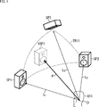
- a listener U11 is in a listening space which is a three-dimensional space, and three speakers SP1 to SP3 are arranged in front of the listener U11.
- the position of the head of the listener U11 is an origin O
- the speakers SP1 to SP3 are located on the surface of a sphere whose center is the origin O.
- gains are distributed to the speakers SP1 to SP3 around the position VSP1.
- the position VSP1 is represented by a three-dimensional vector P having the origin O as a start point and the position VSP1 as an end point.
- the vector L 1 can be represented by a linear sum of the vector L 3.
- equation (1) can be modified to obtain equation (2).
- the coefficients g 1 through coefficient g 3 which was calculated such expressions (2) as the gain, and outputs an audio object signal is a signal of sound of the audio objects to the speaker SP1 to speaker SP3,
- the sound image can be localized at the position VSP1.
- the inverse matrix L 123 -1 can be obtained in advance. Therefore, in VBAP, rendering can be performed with relatively easy calculation, that is, with a small amount of operation.
- the sound image can be properly localized with a small amount of calculation if rendering is performed by panning processing such as VBAP.
- one or more rendering methods are selected from panning processing and rendering processing using a head-related transfer function filter (hereinafter also referred to as head-related transfer function processing) according to the position of the audio object, Made to do the rendering process.
- head-related transfer function processing hereinafter also referred to as head-related transfer function processing
- the rendering method is selected based on the relative positional relationship between the listening position, which is the position of the listener in the listening space, and the position of the audio object.
- panning processing such as VBAP is selected as the rendering method.
- head related transfer function processing is selected as the rendering method.
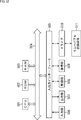
- FIG. 2 is a diagram illustrating a configuration example of an embodiment of a signal processing device to which the present technology is applied.
- the signal processing device 11 illustrated in FIG. 2 includes a core decoding processing unit 21 and a rendering processing unit 22.
- the core decoding processing unit 21 receives and decodes (decodes) the transmitted input bit stream, and supplies the audio object position information and the audio object signal obtained as a result to the rendering processing unit 22. In other words, the core decoding processing unit 21 acquires audio object position information and an audio object signal.
- the audio object signal is an audio signal for reproducing the sound of the audio object.
- the audio object position information is metadata of an audio object, that is, an audio object signal, which is required for rendering performed in the rendering processing unit 22.
- the audio object position information is information indicating the position in the three-dimensional space of the audio object, that is, in the listening space.
- the rendering processing unit 22 generates an output audio signal based on the audio object position information and the audio object signal supplied from the core decoding processing unit 21 and supplies the output audio signal to a speaker, a recording unit, or the like in the subsequent stage.
- the rendering processing unit 22 selects a rendering method based on the audio object position information, that is, any one of a panning process, a head transfer function process, or a panning process and a head transfer function process as a rendering process. .
- the rendering processing unit 22 performs the selected rendering processing to perform rendering on a playback device such as a speaker or headphone, which is an output destination of the output audio signal, and generates an output audio signal.
- the rendering processing unit 22 may select one or more rendering methods from among three or more different rendering methods including panning processing and head related transfer function processing.
- the rendering processing unit 22 is configured, for example, as shown in FIG.
- the rendering processing unit 22 includes a rendering method selection unit 51, a panning processing unit 52, a head related transfer function processing unit 53, and a mixing processing unit 54.
- the rendering method selection unit 51 is supplied with audio object position information and an audio object signal from the core decoding processing unit 21.
- the rendering method selection unit 51 selects, based on the audio object position information supplied from the core decoding processing unit 21, a method of rendering processing for an audio object, that is, a rendering method, for each audio object.
- the rendering method selection unit 51 is configured to receive at least the panning processing unit 52 and the head related transfer function processing unit 53 of the audio object position information and the audio object signal supplied from the core decoding processing unit 21 according to the selection result of the rendering method. Supply to either one.
- the panning processing unit 52 performs panning processing based on the audio object position information and the audio object signal supplied from the rendering method selecting unit 51, and supplies the panning processing output signal obtained as a result to the mixing processing unit 54.
- the panning processing output signal is an audio signal of each channel for reproducing the sound of the audio object so that the sound image of the sound of the audio object is localized at the position in the listening space indicated by the audio object position information. is there.
- the channel configuration of the output destination of the output audio signal is predetermined, and the audio signal of each channel of that channel configuration is generated as a panning processing output signal.
- the output destination of the output audio signal is the speaker system including the speakers SP1 to SP3 shown in FIG. 1, for example, audio signals of channels corresponding to the speakers SP1 to SP3 are output as panning processing output signals. It is generated.
- an audio signal obtained by multiplying the audio object signal supplied from the rendering method selection unit 51 by the coefficient g 1 which is gain is A panning process output signal of a channel corresponding to the speaker SP1 is used.
- the audio object signal, the audio signal obtained by multiplying each of the coefficients g 2 and the coefficient g 3 is a panning process output signal of the channel corresponding to each of the speakers SP2 and the speaker SP3.
- any processing such as VBAP adopted according to the MPEG-H Part 3: 3D audio standard or a panning method called Speaker-anchored coordinates panner is performed as the panning processing, for example. You may do so.
- VBAP may be selected as the rendering method, or Speaker-anchored coordinates panner may be selected.
- the head related transfer function processing unit 53 performs head related transfer function processing based on the audio object position information and the audio object signal supplied from the rendering method selection unit 51, and the head related transfer function processing output signal obtained as a result is obtained The signal is supplied to the mixing processing unit 54.
- the head related transfer function processing output signal is for each channel for reproducing the sound of the audio object so that the sound image of the sound of the audio object is localized at the position in the listening space indicated by the audio object position information. It is an audio signal.
- the head related transfer function processing output signal corresponds to a panning processing output signal
- the head related transfer function processing output signal and the panning processing output signal are head related transfer function processing when generating an audio signal. Whether it is processing or panning processing is different.
- the above-described panning processing unit 52 and head related transfer function processing unit 53 function as a rendering processing unit that performs rendering processing by the rendering method selected by the rendering method selection unit 51, such as panning processing and head related transfer function processing.
- the mixing processing unit 54 outputs an output audio signal based on at least one of the panning processing output signal supplied from the panning processing unit 52 and the head-related transfer function processing output signal supplied from the head-related transfer function processing unit 53. Generate and output to the latter stage.
- audio object position information of one audio object and an audio object signal are stored in the input bit stream.
- the mixing processing unit 54 performs correction processing to generate an output audio signal.
- the panning processing output signal and the head related transfer function processing output signal are synthesized (blended) for each channel to be an output audio signal.
- the mixing processing unit 54 uses the supplied signal as it is as an output audio signal. .
- audio object position information and audio object signals of a plurality of audio objects are stored in the input bit stream.
- the mixing processing unit 54 performs correction processing as necessary to generate an output audio signal for each audio object.
- the mixing processing unit 54 performs mixing processing of adding (combining) the output audio signal of each audio object obtained as described above for each channel, and the output audio signal of each channel obtained as a result is finally obtained.
- Output audio signal That is, the output audio signals of the same channel obtained for each audio object are added to be the final output audio signal of that channel.
- the mixing processing unit 54 functions as an output audio signal generation unit that generates an output audio signal by performing correction processing or mixing processing that combines the panning processing output signal and the head-related transfer function processing output signal as necessary. Function.
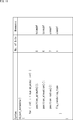
- the audio object position information described above is encoded using, for example, the format shown in FIG. 4 at predetermined time intervals (every predetermined number of frames), and is stored in the input bit stream.
- number_objects indicates the number of audio objects included in the input bit stream.
- tcimsbf is an abbreviation of "Two's complement integer, most significant (sign) bit first", and the sign bit indicates the first two's complement.
- Uimsbf is an abbreviation of "Unsigned integer, most significant bit first”, and the most significant bit indicates a leading unsigned integer.
- position_azimuth [i] As Furthermore, “position_azimuth [i]”, “position_elevation [i]”, and “position_radius [i]” respectively indicate audio object position information of the ith audio object included in the input bit stream.
- position_azimuth [i] indicates the azimuth angle of the position of the audio object in the spherical coordinate system
- position_elevation [i] indicates the elevation angle of the position of the audio object in the spherical coordinate system.
- position_radius [i] indicates the distance to the position of the audio object in the spherical coordinate system, that is, the radius.
- the X axis, the Y axis, and the Z axis which are perpendicular to one another through the origin O are axes of the three-dimensional orthogonal coordinate system.
- the position of the audio object OB11 in the space is X1 which is the X coordinate indicating the position in the X axis direction
- Y1 which is the Y coordinate indicating the position in the Y axis direction
- Z1 which is a Z coordinate indicating X
- the azimuth position_azimuth, elevation angle position_elevation, and radius position_radius are used to represent the position of the audio object OB11 in space.
- a straight line connecting the origin O and the position of the audio object OB11 in the listening space be a straight line r
- a straight line obtained by projecting the straight line r on the XY plane be a straight line L.
- an angle ⁇ formed between the X axis and the straight line L is taken as an azimuth angle position_azimuth indicating the position of the audio object OB11, and this angle ⁇ corresponds to the azimuth angle position_azimuth [i] shown in FIG.
- an angle ⁇ formed between the straight line r and the XY plane is set as an elevation angle position_elevation indicating the position of the audio object OB11, and a length of the straight line r is set as a radius position_radius indicating the position of the audio object OB11.
- the angle ⁇ corresponds to the elevation angle position_elevation [i] shown in FIG. 4, and the length of the straight line r corresponds to the radius position_radius [i] shown in FIG.
- the position of the origin O is the position of a listener (user) who listens to the sound of the content including the sound of the audio object etc.
- the positive direction of the X direction (X axis direction), that is, the near direction in FIG.
- the front direction viewed from the listener is a positive direction in the Y direction (Y axis direction), that is, the right direction in FIG. 5 is the left direction viewed from the listener.
- the position of the audio object is represented by spherical coordinates.
- the position of the audio object in the listening space indicated by such audio object position information is a physical quantity that changes at predetermined time intervals.
- the sound image localization position of the audio object can be moved according to the change of the audio object position information.
- FIG. 6 to FIG. 8 parts corresponding to each other are given the same reference numerals, and the description thereof will be omitted as appropriate. Further, in the present technology, it is assumed that the listening space is a three-dimensional space, but the present technology is also applicable to the case where the listening space is a two-dimensional plane. 6 to 8, in order to simplify the description, it is assumed that the listening space is a two-dimensional plane.
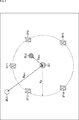
- FIG. 6 there is a listener U21 who is a user who listens to the content sound at the position of the origin O, and used to reproduce the sound of the content on the circumference of a circle of radius R SP centered on the origin O It is assumed that five speakers SP11 to SP15 which are to be connected are disposed. That is, on a horizontal plane including the origin O, the distance from the origin O to each of the speakers SP11 to SP15 is the radius R SP .
- the origin O that is, the distance from the listener U21 to the audio object OBJ1 is R OBJ1
- R OBJ2 the distance from the origin O to the audio object OBJ2 .
- the distance R OBJ1 is a value larger than the radius R SP .
- the distance R OBJ2 is a value smaller than the radius R SP .
- the distance R OBJ1 and the distance R OBJ2 are radius position_radius [i] included in the audio object position information of each of the audio object OBJ1 and the audio object OBJ2.
- the rendering method selection unit 51 selects a rendering method to be performed on the audio object OBJ1 and the audio object OBJ2 by comparing the predetermined radius R SP with the distance R OBJ1 and the distance R OBJ2 .
- panning processing is selected as the rendering method.
- head related transfer function processing is selected as the rendering method.
- the panning process is selected for the audio object OBJ1 of which the distance R OBJ1 is equal to or greater than the radius R SP in this example, and the audio object position information of the audio object OBJ1 and the audio object signal are supplied to the panning process unit 52. Then, in the panning processing unit 52, processing such as VBAP described with reference to FIG. 1 is performed on the audio object OBJ1 as panning processing.
- the head related transfer function processing is selected, and the audio object position information of the audio object OBJ2 and the audio object signal are supplied to the head related transfer function processing unit 53. Be done.
- head related transfer function processing unit 53 head related transfer function processing using the head related transfer function is performed on the audio object OBJ2 as shown in FIG. 7, for example, and the head related transfer function for the audio object OBJ2 is A processing output signal is generated.
- the head related transfer function processing unit 53 prepares each of the left and right ears prepared in advance with respect to the position in the listening space of the audio object OBJ2 based on the audio object position information of the audio object OBJ2. Read out the head related transfer function, more specifically the head related transfer function filter.
- sampling points For example, several points in the area inside the circle (on the side of the origin O) in which the speakers SP11 to SP15 are arranged are used as sampling points. Then, for each of the sampling points, a head-related transfer function indicating the transfer characteristic of sound from the sampling point to the ear of the listener U21 at the origin O is prepared in advance for each of the left and right ears. Shall be held by
- the head related transfer function processing unit 53 reads the head related transfer function of the sampling point closest to the position of the audio object OBJ2 as the head related transfer function of the position of the audio object OBJ2.
- a head-related transfer function at the position of the audio object OBJ2 may be generated by interpolation processing such as linear interpolation from head-related transfer functions of several sampling points in the vicinity of the position of the audio object OBJ2.
- a head-related transfer function on the position of the audio object OBJ2 may be stored in the metadata of the input bit stream.
- the rendering method selection unit 51 supplies the audio object position information and the head-related transfer function supplied from the core decoding processing unit 21 to the head-related transfer function processing unit 53 as metadata.
- the head-related transfer function with respect to the position of the audio object will in particular also be referred to as the object position head-related transfer function.
- the head related transfer function processing unit 53 outputs an audio signal (a signal of sound presented to the ears of the left and right ears of the listener U21)
- a speaker (channel) supplied as a head-related transfer function processing output signal) is selected.
- the speaker to which the output audio signal of the sound to be presented to the left or right ear of the listener U21 is to be output is also referred to as a selection speaker in particular.
- the head related transfer function processing unit 53 selects the speaker SP11 disposed at the position closest to the audio object OBJ2 on the left side of the audio object OBJ2 as viewed from the listener U21 as a selected speaker for the left ear Do. Similarly, the head related transfer function processing unit 53 selects the speaker SP13 disposed at the position closest to the audio object OBJ2 on the right side of the audio object OBJ2 as viewed from the listener U21 as a selection speaker for the right ear .
- the head related transfer function processing unit 53 obtains a head related transfer function, more specifically, a filter for the head related transfer function with respect to the arrangement positions of those selected speakers.
- the head related transfer function processing unit 53 appropriately performs interpolation processing based on the head related transfer function of each sampling point held in advance, and the head at each position of the speaker SP11 and the speaker SP13 Generate a transfer function.
- the head related transfer function about the arrangement position of each speaker may be previously held in the head related transfer function processing unit 53, or the head related transfer function of the arrangement position of the selected speaker is metadata as metadata. It may be stored in the input bit stream.
- the head-related transfer function of the arrangement position of the selected speaker will be particularly referred to as a speaker position head-related transfer function.
- the head related transfer function processing unit 53 convolutes the audio object signal of the audio object OBJ2 with the object position head related transfer function of the left ear, and the signal obtained as a result, the speaker position head related transmission of the left ear The function is convoluted to generate an audio signal for the left ear.
- the head related transfer function processing unit 53 convolutes the audio object signal of the audio object OBJ2 with the object position head related transfer function of the right ear, and the resulting signal, and the speaker position head of the right ear A partial transfer function is convoluted to generate an audio signal for the right ear.
- the audio signal for the left ear and the audio signal for the right ear present the sound of the audio object OBJ2 so that the listener U21 can perceive it as if the sound could be heard from the position of the audio object OBJ2. It is a signal to do. That is, it is an audio signal that realizes sound image localization to the position of the audio object OBJ2.
- the reproduced sound O2 SP11 is presented to the left ear of the listener U21, and at the same time the sound is transmitted by the speaker SP13 based on the audio signal for the right ear
- the reproduced sound O2 SP13 is presented to the right ear of the listener U21.
- the listener U21 is perceived as if the sound of the audio object OBJ2 is heard from the position of the audio object OBJ2.
- the reproduction sound O2 SP11 is represented by an arrow connecting the speaker SP11 and the left ear of the listener U21
- the reproduction sound O2 SP13 is represented by an arrow connecting the speaker SP13 and the right ear of the listener U21.
- the reproduced sound O2 SP11-CT is a crosstalk component of the reproduced sound O2 SP11 that leaks to the right ear of the listener U21. That is, the reproduced sound O2 SP11-CT is a crosstalk component of the reproduced sound O2 SP11 that reaches the ear (here, the right ear) different from the purpose of the listener U21.
- the reproduced sound O2 SP13-CT propagating from the speaker SP13 to the left ear of the listener U21 is the speaker SP13 and the listener U21. It is represented by an arrow connecting the left ear.
- the reproduced sound O2 SP13-CT is a crosstalk component of the reproduced sound O2 SP13 .
- the head related transfer function processing unit 53 Based on the audio signal for the left ear, the head related transfer function processing unit 53 generates a cancel signal for canceling the reproduced sound O2 SP11-CT which is a crosstalk component, and the audio signal for the left ear and the cancel signal And generate a final left-ear audio signal. Then, the final left-ear audio signal including the crosstalk cancellation component and the space transfer function correction component obtained in this manner is taken as the head-related transfer function processed output signal of the channel corresponding to the speaker SP11. Ru.
- the head related transfer function processing unit 53 based on the audio signal for the right ear, the head related transfer function processing unit 53 generates a cancellation signal for canceling the reproduced sound O2 SP13-CT , which is a crosstalk component, and generates an audio signal for the right ear.
- a final right ear audio signal is generated based on the cancellation signal. Then, the final right-ear audio signal including the crosstalk cancellation component and the space transfer function correction component obtained in this manner is used as a head transfer function processing output signal of the channel corresponding to the speaker SP13.
- transaural process The process of rendering on the speaker including the crosstalk correction process of generating the audio signal for the left ear and the audio signal for the right ear as described above is called transaural process.
- transaural processing is described in detail, for example, in JP-A-2016-140039.
- an example in which one speaker is selected for each of the left and right ears as the selected speaker has been described, but two or more speakers are selected for each of the left and right ears as the selected speakers.
- An audio signal for the left ear or an audio signal for the right ear may be generated.
- all the speakers constituting the speaker system such as the speakers SP11 to SP15, may be selected as the selection speakers.
- binaural processing may be performed as head related transfer function processing.
- Binaural processing is rendering processing for rendering an audio object (audio object signal) on an output unit such as headphones worn on the left and right ears using a head-related transfer function.
- panning processing for distributing gains to the left and right channels is selected as a rendering method.
- binaural processing is selected as the rendering method.
- the audio object may gradually approach the listener U21 with time from a position at a distance greater than or equal to the radius R SP .
- the audio object OBJ2 that is at a position longer than the radius R SP as viewed from the listener U21 at a predetermined time is depicted as approaching the listener U21 with time.
- an area inside a circle of radius R SP centered at the origin O is a speaker radius area RG11
- an area inside a circle of radius R HRTF centered at the origin O is a HRTF area RG12
- a speaker radius area RG11 the region is not a HRTF region RG12 of the transition region R TS.
- the transition area R TS is an area where the distance from the origin O (the listener U 21) is a distance between the radius R HRTF and the radius R SP .
- the rendering method switches suddenly when the audio object OBJ 2 reaches the inside of the transition area R TS. It will be. Then, a discontinuous point occurs in the sound of the audio object OBJ2, which may cause a sense of discomfort.
- panning processing is selected as the rendering method.
- HRTF processing is selected as the rendering method.
- the correction process is performed so as closer to the panning process output signal.
- the panning processing output signal of the channel corresponding to the speaker SP11 generated by the panning processing is O2 PAN11 (R 0 )
- the panning processing output signal of the channel corresponding to the speaker SP13 is O2 PAN13 (R 0 ).
- the head related transfer function processed output signal of the channel corresponding to the speaker SP11 generated by the head related transfer function processing is O2 HRTF11 (R 0 ), and the head related transfer function processed output signal of the channel corresponding to the speaker SP13 It is set as O2 HRTF13 (R 0 ).
- the output audio signal O2 SP11 (R 0 ) of the channel corresponding to the speaker SP11 and the output audio signal O2 SP13 (R 0 ) of the channel corresponding to the speaker SP13 are calculated by calculating the following equation (3) You can get it. That is, in the mixing processing unit 54, the calculation of the following Expression (3) is performed as the correction processing.
- the panning process output signal and the head transmitted proration ratio according to the distance R 0 to the audio object function processing adds the output signal (synthesis) to A correction process is performed to obtain an output audio signal.
- the output of the panning process and the output of the head related transfer function process are proportionally divided according to the distance R 0 .
- the listening position where the listener is present is the origin O
- the case where the listening position is always the same position is described as an example, but the listener may move with time.
- the position of the listener at each time may be set as the origin O, and the relative position of the audio object or the speaker viewed from the origin O may be recalculated.
- step S11 the core decoding processing unit 21 decodes (decodes) the received input bit stream, and supplies the audio object position information and the audio object signal obtained as a result to the rendering method selecting unit 51.
- step S12 the rendering method selection unit 51 determines, based on the audio object position information supplied from the core decode processing unit 21, whether to perform panning processing as rendering of the audio object.
- step S12 when the distance from the listener indicated by the audio object position information to the audio object is equal to or larger than the radius R HRTF described with reference to FIG. That is, at least panning is selected as the rendering method.
- step S12 when there is an instruction input instructing whether or not to perform the panning process by a user who operates the signal processing apparatus 11 or the like, and the execution of the panning process is designated (instruction) by the instruction input, step S12. It may be determined that the panning process is to be performed. In this case, the rendering method to be executed is selected by the instruction input by the user or the like.
- step S12 If it is determined in step S12 that the panning process is not to be performed, the process of step S13 is not performed, and then the process proceeds to step S14.
- step S12 when it is determined in step S12 that the panning process is to be performed, the rendering method selecting unit 51 supplies the audio object position information and the audio object signal supplied from the core decoding processing unit 21 to the panning processing unit 52. After that, the process proceeds to step S13.
- step S13 the panning processing unit 52 performs panning processing based on the audio object position information and the audio object signal supplied from the rendering method selecting unit 51, and generates a panning processing output signal.
- step S13 the above-described VBAP or the like is performed as the panning process.
- the panning processing unit 52 supplies the panning processing output signal obtained by the panning processing to the mixing processing unit 54.
- step S14 If it is determined that the process of step S13 is performed or if the panning process is not performed in step S12, the process of step S14 is performed.
- step S14 the rendering method selection unit 51 determines, based on the audio object position information supplied from the core decode processing unit 21, whether or not head-related transfer function processing is to be performed as rendering of the audio object.
- step S14 when the distance from the listener indicated by the audio object position information to the audio object is less than the radius R SP described with reference to FIG. That is, at least head-related transfer function processing is selected as the rendering method.
- step S14 there is an instruction input for instructing whether or not to perform head-related transfer function processing by a user who operates the signal processing apparatus 11 or the like, and execution of the head-related transfer function processing is designated (instruction) by the instruction input. In this case, it may be determined in step S14 that head related transfer function processing is to be performed.
- step S14 If it is determined in step S14 that head-related transfer function processing is not to be performed, the processing in steps S15 to S19 is not performed, and then the processing proceeds to step S20.
- step S14 when it is determined in step S14 that the head-related transfer function processing is to be performed, the rendering method selection unit 51 performs head-related transfer function on the audio object position information and the audio object signal supplied from the core decoding processing unit 21. After supplying the processing unit 53, the process proceeds to step S15.
- step S ⁇ b> 15 the head related transfer function processing unit 53 acquires an object position head related transfer function of the position of the audio object based on the audio object position information supplied from the rendering method selection unit 51.
- the object position head-related transfer function may be read out in advance, or may be obtained by interpolation processing from a plurality of head-related transfer functions held in advance, or from the input bit stream It may be read out.
- step S16 the head related transfer function processing unit 53 selects a selected speaker based on the audio object position information supplied from the rendering method selection unit 51, and acquires a speaker position head related transfer function of the selected speaker position. .
- the speaker position head transfer function may be read out in advance, or may be obtained by interpolation processing from a plurality of head transfer functions held in advance, or from the input bit stream It may be read out.
- step S17 the head related transfer function processing unit 53 convolutes the audio object signal supplied from the rendering method selection unit 51 with the object position head related transfer function obtained in step S15 for each of the left and right ears.
- step S18 the head related transfer function processing unit 53 convolutes the audio signal obtained in step S17 and the speaker position head related transfer function for each of the left and right ears. Thereby, an audio signal for the left ear and an audio signal for the right ear can be obtained.
- step S19 the head related transfer function processing unit 53 generates a head related transfer function processing output signal based on the audio signal for the left ear and the audio signal for the right ear, and supplies the generated signal to the mixing processing unit 54.
- the cancel signal is appropriately generated to generate the final head related transfer function processing output signal.
- the transaural process described with reference to FIG. 8 as head-related transfer function processing is performed, and a head-related transfer function processed output signal is generated.
- a head-related transfer function processed output signal is generated.
- the output destination of the output audio signal is not a speaker but a playback device such as headphones, binaural processing or the like is performed as head-related transfer function processing, and a head-related transfer function processing output signal is generated.
- step S19 If the process of step S19 is performed or it is determined in step S14 that the head related transfer function process is not performed, the process of step S20 is performed thereafter.
- step S20 the mixing processing unit 54 combines the panning processing output signal supplied from the panning processing unit 52 and the head-related transfer function processing output signal supplied from the head-related transfer function processing unit 53, and outputs an output audio signal.
- step S20 the calculation of the equation (3) described above is performed as a correction process to generate an output audio signal.
- step S13 the process of step S13 is performed, and the process of step S15 to step S19 is not performed, or the process of step S15 to step S19 is performed and the process of step S13 is not performed. There is no processing.
- the panning process output signal obtained as a result is used as the output audio signal as it is.
- the head-related transfer function processed output signal obtained as a result is used as an output audio signal as it is.
- the mixing processing unit 54 performs the mixing process It will be. That is, the output audio signals obtained for each audio object are added (combined) for each channel to be one final output audio signal.
- the mixing processing unit 54 outputs the obtained output audio signal to the subsequent stage, and the audio output processing ends.
- the signal processing apparatus 11 selects one or more rendering methods from the plurality of rendering methods based on the audio object position information, that is, based on the distance from the listening position to the audio object. Then, the signal processing device 11 performs rendering according to the selected rendering method to generate an output audio signal.
- panning processing is selected as the rendering method.
- the audio object is sufficiently far from the listening position, it is not necessary to consider the difference in the arrival time of the sound to the listener's left and right ears, and the sound image is localized with sufficient reproducibility even with a small amount of computation. be able to.
- the audio object is at a position close to the listening position, for example, HRTF processing is selected as the rendering method.
- HRTF processing is selected as the rendering method.
- the sound image can be localized with sufficient reproducibility, although the amount of calculation increases somewhat.
- the head-related transfer function processing is selected as the rendering method. It may be selected.
- head-related transfer function processing is selected as a rendering method
- head-related transfer functions are performed using head-related transfer functions according to the distance from the listening position to the audio object, It is possible to prevent the occurrence of discontinuous points.
- the head related transfer function processing unit 53 As the distance to the audio object is longer, that is, as the position of the audio object is closer to the boundary position of the speaker radius area RG11, the head related transfer functions of the left and right ears are substantially It should be made to become the same thing.
- the increase in the degree of similarity of the head transfer functions can mean that the difference between the head transfer functions for the left ear and the head transfer functions for the right ear is reduced.
- a common head related transfer function is used for the left and right ears.
- the head related transfer function processing unit 53 determines the actual position of the audio object. The one close to the head related transfer function obtained by the measurement is used.
- the head transfer function processing output signal becomes the same as the panning processing output signal. It is.
- the resource availability of the signal processing device 11, the importance of the audio object, etc. may be taken into consideration.
- the rendering method selection unit 51 selects head-related transfer function processing as the rendering method. Conversely, the rendering method selection unit 51 selects panning processing as the rendering method when the resource availability of the signal processing device 11 is small.
- the rendering method selection unit 51 selects head-related transfer function processing as the rendering method.
- the rendering method selection unit 51 selects panning as the rendering method.
- the importance of each audio object may be included in the input bitstream as metadata of the audio objects. Also, the importance of the audio object may be designated by an external operation input or the like.
- rendering for headphone reproduction may be performed using the concept of a virtual speaker.
- the computational cost for performing head-related transfer function processing becomes large, as in the case of rendering on a speaker.
- the output destination of the output audio signal is a playback device such as headphones that performs playback on the left and right two channels, and once rendering to a virtual speaker, the playback device further uses a head related transfer function.
- the present technology is also applicable when rendering is performed.
- the rendering method selection unit 51 may select one or more rendering methods at the time of rendering from among a plurality of rendering methods, for example, regarding the speakers SP11 to SP15 illustrated in FIG. 8 as virtual speakers. .
- the panning method is selected as the rendering method It should be done.
- rendering to a virtual speaker is performed by panning processing. Then, based on the audio signal obtained by the panning process and the head transfer function for each of the left and right ears from the virtual speaker to the listening position, the head transfer function processing further renders the headphone or the like to a reproduction device Is performed to generate an output audio signal.
- head related transfer function processing may be selected as the rendering method.
- binaural processing as head-related transfer function processing directly performs rendering on a reproduction device such as headphones to generate an output audio signal.
- the encoding format based on the present technology that is, the metadata of the audio object is as shown in FIG. 10, for example.
- radius_hrtf is information (parameter) indicating the distance from the listening position (origin O), which is used to determine whether or not head-related transfer function processing is selected as the rendering method.
- radius_panning is information (parameter) indicating the distance from the listening position (origin O), which is used to determine whether or not panning is selected as the rendering method.
- the metadata stores the audio object position information of each audio object, the distance radius_hrtf, and the distance radius_panning. These pieces of information are read by the core decoding processing unit 21 as metadata. It is output to the rendering method selection unit 51.
- the rendering method selection unit 51 selects head related transfer function processing as the rendering method if the distance from the listener to the audio object is equal to or less than the distance radius_hrtf regardless of the radius R SP indicating the distance to each speaker Do. In addition, the rendering method selection unit 51 does not select head-related transfer function processing as the rendering method if the distance from the listener to the audio object is longer than the distance radius_hrtf.
- the rendering method selection unit 51 selects panning processing as the rendering method if the distance from the listener to the audio object is equal to or more than the distance radius_panning. In addition, the rendering method selection unit 51 does not select the panning process as the rendering method if the distance from the listener to the audio object is shorter than the distance radius_panning.
- the distance radius_hrtf and the distance radius_panning may be the same distance or different distances from each other.
- both the panning process and the head-related transfer function process are selected as the rendering method when the distance from the listener to the audio object is greater than or equal to the distance radius_panning and less than or equal to the distance radius_hrtf.
- the mixing processing unit 54 performs the calculation of the equation (3) described above based on the panning process output signal and the head-related transfer function process output signal to generate an output audio signal. That is, according to the distance from the listener to the audio object, the correction processing divides the panning processing output signal and the head related transfer function processing output signal to generate an output audio signal.
- ⁇ Modified Example 1 of Third Embodiment> On selection of rendering method> Furthermore, on the output side of the input bit stream, that is, the creator side of the content, a rendering method at each time such as a frame is selected for each audio object, and selection instruction information indicating the selection result is input as metadata. It may be stored in a stream.
- the selection instruction information is information indicating an instruction for selecting a rendering method for the audio object
- the rendering method selection unit 51 performs rendering based on the selection instruction information supplied from the core decoding processing unit 21. Choose a method. In other words, the rendering method selection unit 51 selects the rendering method designated by the selection instruction information for the audio object signal.
- the encoding format based on the present technology that is, the metadata of the audio object is as shown in FIG. 11, for example.
- Flg_rendering_type is selection instruction information indicating which rendering method to use.
- the selection instruction information flg_rendering_type is flag information (parameter) indicating whether to select panning processing or head-related transfer function processing as the rendering method.
- the value “0” of the selection instruction information flg_rendering_type indicates that the panning process is selected as the rendering method.
- the value “1” of the selection indication information flg_rendering_type indicates that the head-related transfer function processing is selected as the rendering method.
- selection designation information flg_rendering_type is stored in the metadata for each audio object for each frame (each time).
- audio object position information and selection instruction information flg_rendering_type are stored in the metadata for each audio object, and these pieces of information are read out by the core decoding processing unit 21 as metadata. , And supplied to the rendering method selection unit 51.
- the rendering method selection unit 51 selects the rendering method according to the value of the selection instruction information flg_rendering_type regardless of the distance from the listener to the audio object. That is, the rendering method selection unit 51 selects panning as the rendering method if the value of the selection instruction information flg_rendering_type is “0”, and transmits the head transmission as the rendering method if the value of the selection instruction information flg_rendering_type is “1”. Select function processing.
- the selection instruction information flg_rendering_type may be any of a plurality of three or more types of values. Good. For example, when the value of the selection instruction information flg_rendering_type is “2”, panning processing and head-related transfer function processing may be selected as the rendering method.
- the present technology as described in, for example, the first to third modifications of the first embodiment, even when there are a large number of audio objects, the amount of computation is reduced while the amount of computation is high. Sound image expression with reproducibility can be realized.
- the present technology is applicable not only to speaker reproduction using an actual speaker, but also to headphone reproduction by rendering using a virtual speaker.
- the series of processes described above can be executed by hardware or software.
- a program that configures the software is installed on a computer.
- the computer includes, for example, a general-purpose personal computer that can execute various functions by installing a computer incorporated in dedicated hardware and various programs.
- FIG. 12 is a block diagram showing an example of a hardware configuration of a computer that executes the series of processes described above according to a program.
- a central processing unit (CPU) 501 a read only memory (ROM) 502, and a random access memory (RAM) 503 are mutually connected by a bus 504.
- CPU central processing unit
- ROM read only memory
- RAM random access memory
- an input / output interface 505 is connected to the bus 504.
- An input unit 506, an output unit 507, a recording unit 508, a communication unit 509, and a drive 510 are connected to the input / output interface 505.
- the input unit 506 includes a keyboard, a mouse, a microphone, an imaging device, and the like.
- the output unit 507 includes a display, a speaker, and the like.
- the recording unit 508 includes a hard disk, a non-volatile memory, and the like.
- the communication unit 509 is formed of a network interface or the like.
- the drive 510 drives a removable recording medium 511 such as a magnetic disk, an optical disk, a magneto-optical disk, or a semiconductor memory.
- the CPU 501 loads, for example, the program recorded in the recording unit 508 into the RAM 503 via the input / output interface 505 and the bus 504, and executes the above-described series. Processing is performed.
- the program executed by the computer (CPU 501) can be provided by being recorded on, for example, a removable recording medium 511 as a package medium or the like. Also, the program can be provided via a wired or wireless transmission medium such as a local area network, the Internet, or digital satellite broadcasting.
- the program can be installed in the recording unit 508 via the input / output interface 505 by attaching the removable recording medium 511 to the drive 510. Also, the program can be received by the communication unit 509 via a wired or wireless transmission medium and installed in the recording unit 508. In addition, the program can be installed in advance in the ROM 502 or the recording unit 508.
- the program executed by the computer may be a program that performs processing in chronological order according to the order described in this specification, in parallel, or when necessary, such as when a call is made. It may be a program to be processed.
- the present technology can have a cloud computing configuration in which one function is shared and processed by a plurality of devices via a network.
- each step described in the above-described flowchart can be executed by one device or in a shared manner by a plurality of devices.
- the plurality of processes included in one step can be executed by being shared by a plurality of devices in addition to being executed by one device.
- present technology can also be configured as follows.
- a rendering method selection unit that selects one or more of a plurality of different rendering methods for rendering a sound image of an audio signal in the listening space; A rendering processing unit that performs the rendering process of the audio signal according to the method selected by the rendering method selection unit.
- the plurality of techniques include panning processing.
- the signal processing apparatus according to any one of (1) to (3), wherein the plurality of techniques include the rendering process using a head related transfer function.
- the signal processing device according to (4), wherein the rendering process using the head related transfer function is a transaural process or a binaural process.
- the rendering processing unit performs the rendering process so that the difference between the head related transfer function for the left ear and the head related transfer function for the right ear decreases as the distance approaches the first distance.
- the signal processing apparatus according to (9), wherein the head related transfer function to be used is selected.
- the rendering method selection unit selects the rendering process using a head related transfer function as a method of the rendering process (7).
- the signal processing device as described.
- the rendering method selection unit performs the rendering process using the panning process and the head related transfer function as a method of the rendering process.
- the signal processing device according to (11).
- An output audio signal generation unit that combines an signal obtained by the panning process and a signal obtained by the rendering process using the head related transfer function to generate an output audio signal Signal processing equipment.
- the signal processing apparatus according to any one of (1) to (5), wherein the rendering method selection unit selects a method specified for the audio signal as a method of the rendering process.
- the signal processor Select one or more rendering methods for localization of the sound image of the audio signal in the listening space from among different methods, A signal processing method for performing the rendering process of the audio signal according to a selected method.
- Reference Signs List 11 signal processing device 21 core decoding processing unit, 22 rendering processing unit, 51 rendering method selecting unit, 52 panning processing unit, 53 head transfer function processing unit, 54 mixing processing unit
Landscapes
- Engineering & Computer Science (AREA)
- Physics & Mathematics (AREA)
- Acoustics & Sound (AREA)
- Signal Processing (AREA)
- Multimedia (AREA)
- Mathematical Physics (AREA)
- Computational Linguistics (AREA)
- Health & Medical Sciences (AREA)
- Audiology, Speech & Language Pathology (AREA)
- Human Computer Interaction (AREA)
- Stereophonic System (AREA)
Abstract
本技術は、少ない演算量で音像の再現性を向上させることができるようにする信号処理装置および方法、並びにプログラムに関する。 信号処理装置は、オーディオ信号の音像を聴取空間内に定位させるレンダリング処理の手法を、互いに異なる複数の手法のなかから1以上選択するレンダリング手法選択部と、レンダリング手法選択部によって選択された手法によりオーディオ信号のレンダリング処理を行うレンダリング処理部とを備える。本技術は信号処理装置に適用することができる。
Description
本技術は、信号処理装置および方法、並びにプログラムに関し、特に、少ない演算量で音像の再現性を向上させることができるようにした信号処理装置および方法、並びにプログラムに関する。
従来、映画やゲーム等でオブジェクトオーディオ技術が使われ、オブジェクトオーディオを扱える符号化方式も開発されている。具体的には、例えば国際標準規格であるMPEG(Moving Picture Experts Group)-H Part 3:3D audio規格などが知られている(例えば、非特許文献1参照)。
このような符号化方式では、従来の2チャンネルステレオ方式や5.1チャンネル等のマルチチャンネルステレオ方式とともに、移動する音源等を独立したオーディオオブジェクトとして扱い、オーディオオブジェクトの信号データとともにオブジェクトの位置情報をメタデータとして符号化することが可能である。
このようにすることで、スピーカの数や配置の異なる様々な視聴環境で再生を行うことができる。また、従来の符号化方式では困難であった特定の音源の音の音量調整や、特定の音源の音に対するエフェクトの追加など、特定の音源の音を再生時に加工することが容易にできる。
例えば非特許文献1の規格では、レンダリング処理に3次元VBAP(Vector Based Amplitude Panning)(以下、単にVBAPと称する)と呼ばれる方式が用いられる。
これは一般的にパニングと呼ばれるレンダリング手法の1つで、聴取位置を原点とする球表面上に存在するスピーカのうち、同じく球表面上に存在するオーディオブジェクトに最も近い3個のスピーカに対しゲインを分配することでレンダリングを行う方式である。
また、VBAP以外にも、例えばゲインをx軸、y軸、およびz軸のそれぞれに対して分配するSpeaker-anchored coordinates pannerと呼ばれるパニング手法によるレンダリング処理も知られている(例えば、非特許文献2参照)。
一方で、パニング処理以外にもオーディオブジェクトをレンダリングする手法として、頭部伝達関数のフィルタを用いる手法も提案されている(例えば、特許文献1参照)。
一般的に、頭部伝達関数を用いて移動するオーディオブジェクトをレンダリングする場合、以下のようにして頭部伝達関数のフィルタを得ることが多い。
すなわち、例えば移動空間範囲内を空間サンプリングし、その空間内の個々の点に対応した多数の頭部伝達関数のフィルタを予め用意することが一般的である。また、例えば一定距離間隔で測定された空間内の各位置の頭部伝達関数を用いて、3次元合成法によって距離補正により所望位置の頭部伝達関数のフィルタを求めるようにすることもある。
上述した特許文献1には、一定距離の球表面をサンプリングして得られた、頭部伝達関数のフィルタの生成に必要なパラメータを用いて、任意距離の頭部伝達関数のフィルタを生成する手法が記載されている。
INTERNATIONAL STANDARD ISO/IEC 23008-3 First edition 2015-10-15 Information technology High efficiency coding and media delivery in heterogeneous environments Part 3: 3D audio
ETSI TS 103 448 v1.1.1(2016-09)
しかしながら、上述した技術では、レンダリングによりオーディオオブジェクトの音の音像を定位させる場合に、少ない演算量で高い音像定位の再現性を得ることは困難であった。すなわち、少ない演算量で、本来意図した位置に音像があるかのように知覚させる音像定位を実現することは困難であった。
例えばパニング処理によるオーディオブジェクトのレンダリングでは、聴取位置が1点であることが前提とされている。この場合、例えばオーディオブジェクトが聴取位置に近いときには、聴取者の左耳へと到達する音波と、聴取者の右耳へと到達する音波との到達時刻の差は無視できないものとなる。
しかし、パニング処理としてVBAPが行われるときには、スピーカが配置された球表面の内側や外側にオーディオブジェクトが位置していても、オーディオオブジェクトが球表面上にあるものとしてレンダリングが行われる。そうすると、オーディオブジェクトが聴取位置に接近した場合、再生時におけるオーディオオブジェクトの音像は期待されるものとは程遠いものとなってしまう。
これに対して、頭部伝達関数を用いたレンダリングでは、オーディオオブジェクトが聴取者に近い位置にある場合でも、高い音像定位の再現性を実現することができる。また、頭部伝達関数のFIR(Finite Impulse Response)フィルタ処理として、FFT(Fast Fourier Transform)やQMF(Quadrature Mirror Filter)等の高速演算処理が存在する。
しかし、これらの頭部伝達関数のFIRフィルタ処理の処理量は、パニングの処理量と比較して非常に多い。そのため、多数のオーディオブジェクトがあるときには、全てのオーディオオブジェクトについて頭部伝達関数を用いたレンダリングを行うことが適切であるとはいえない場合もある。
本技術は、このような状況に鑑みてなされたものであり、少ない演算量で音像の再現性を向上させることができるようにするものである。
本技術の一側面の信号処理装置は、オーディオ信号の音像を聴取空間内に定位させるレンダリング処理の手法を、互いに異なる複数の手法のなかから1以上選択するレンダリング手法選択部と、前記レンダリング手法選択部によって選択された手法により前記オーディオ信号の前記レンダリング処理を行うレンダリング処理部とを備える。
本技術の一側面の信号処理方法またはプログラムは、オーディオ信号の音像を聴取空間内に定位させるレンダリング処理の手法を、互いに異なる複数の手法のなかから1以上選択し、選択された手法により前記オーディオ信号の前記レンダリング処理を行うステップを含む。
本技術の一側面においては、オーディオ信号の音像を聴取空間内に定位させるレンダリング処理の手法が、互いに異なる複数の手法のなかから1以上選択され、選択された手法により前記オーディオ信号の前記レンダリング処理が行われる。
本技術の一側面によれば、少ない演算量で音像の再現性を向上させることができる。
なお、ここに記載された効果は必ずしも限定されるものではなく、本開示中に記載された何れかの効果であってもよい。
以下、図面を参照して、本技術を適用した実施の形態について説明する。
〈第1の実施の形態〉
〈本技術について〉
本技術は、オーディオオブジェクトのレンダリングを行う場合に、オーディオオブジェクトごとに、そのオーディオオブジェクトの聴取空間内の位置に応じて、互いに異なる複数のレンダリング手法のなかから1以上の手法を選択することで、少ない演算量でも音像の再現性を向上させることができるようにするものである。すなわち、本技術は、少ない演算量でも本来意図した位置に音像があるかのように知覚させる音像定位を実現することができるようにするものである。
〈本技術について〉
本技術は、オーディオオブジェクトのレンダリングを行う場合に、オーディオオブジェクトごとに、そのオーディオオブジェクトの聴取空間内の位置に応じて、互いに異なる複数のレンダリング手法のなかから1以上の手法を選択することで、少ない演算量でも音像の再現性を向上させることができるようにするものである。すなわち、本技術は、少ない演算量でも本来意図した位置に音像があるかのように知覚させる音像定位を実現することができるようにするものである。
特に本技術では、オーディオ信号の音像を聴取空間内に定位させるレンダリング処理の手法、つまりレンダリング手法として、演算量(計算負荷)と音像定位性能が互いに異なる複数のレンダリング手法のなかから、1以上のレンダリング手法が選択される。
なお、ここではレンダリング手法の選択対象となるオーディオ信号が、オーディオオブジェクトのオーディオ信号(オーディオオブジェクト信号)である場合を例として説明する。しかし、これに限らず、レンダリング手法の選択対象とするオーディオ信号は、聴取空間内に音像を定位させようとするオーディオ信号であれば、どのようなものであってもよい。
上述したようにVBAPでは、聴取空間における聴取位置を原点とする球表面上に存在するスピーカのうち、同じく球表面上に存在するオーディオブジェクトに最も近い3個のスピーカに対しゲインが分配される。
例えば図1に示すように、3次元空間である聴取空間に聴取者U11がおり、その聴取者U11の前方に3つのスピーカSP1乃至スピーカSP3が配置されているとする。
また、聴取者U11の頭部の位置を原点Oとし、その原点Oを中心とする球の表面上にスピーカSP1乃至スピーカSP3が位置しているとする。
いま、球表面上におけるスピーカSP1乃至スピーカSP3に囲まれる領域TR11内にオーディオオブジェクトが存在しており、そのオーディオオブジェクトの位置VSP1に音像を定位させることを考えるとする。
そのような場合、VBAPでは、オーディオオブジェクトについて、位置VSP1の周囲にあるスピーカSP1乃至スピーカSP3に対してゲインが分配されることになる。
具体的には、原点Oを基準(原点)とする3次元座標系において、原点Oを始点とし、位置VSP1を終点とする3次元のベクトルPにより位置VSP1を表すこととする。
また、原点Oを始点とし、各スピーカSP1乃至スピーカSP3の位置を終点とする3次元のベクトルをベクトルL1乃至ベクトルL3とすると、ベクトルPは次式(1)に示すように、ベクトルL1乃至ベクトルL3の線形和によって表すことができる。
ここで、式(1)においてベクトルL1乃至ベクトルL3に乗算されている係数g1乃至係数g3を算出し、これらの係数g1乃至係数g3を、スピーカSP1乃至スピーカSP3のそれぞれから出力する音のゲインとすれば、位置VSP1に音像を定位させることができる。
例えば係数g1乃至係数g3を要素とするベクトルをg123=[g1,g2,g3]とし、ベクトルL1乃至ベクトルL3を要素とするベクトルをL123=[L1,L2,L3]とすると、上述した式(1)を変形して次式(2)を得ることができる。
このような式(2)を計算して求めた係数g1乃至係数g3をゲインとして用いて、オーディオオブジェクトの音の信号であるオーディオオブジェクト信号を各スピーカSP1乃至スピーカSP3に出力することで、位置VSP1に音像を定位させることができる。
なお、各スピーカSP1乃至スピーカSP3の配置位置は固定されており、それらのスピーカの位置を示す情報は既知であるため、逆行列であるL123
-1は事前に求めておくことができる。そのため、VBAPでは比較的容易な計算で、つまり少ない演算量でレンダリングを行うことが可能である。
したがって、オーディオオブジェクトが聴取者U11から十分離れた位置にある場合には、VBAP等のパニング処理によりレンダリングを行えば、少ない演算量で適切に音像を定位させることができる。
しかし、オーディオオブジェクトが聴取者U11に近い位置にあるときには、VBAP等のパニング処理では、聴取者U11の左右の耳へと到達する音波の到達時刻の差を表現することは困難であり、十分に高い音像の再現性を得ることはできなかった。
そこで、本技術では、オーディオオブジェクトの位置に応じてパニング処理および頭部伝達関数のフィルタを用いたレンダリング処理(以下、頭部伝達関数処理とも称する)のなかから1以上のレンダリング手法を選択し、レンダリング処理を行うようにした。
例えばレンダリング手法は、聴取空間における聴取者の位置である聴取位置と、オーディオオブジェクトの位置との相対的な位置関係に基づいて選択される。
具体的には、一例として、例えばスピーカが配置された球表面上または球表面の外側にオーディオオブジェクトが位置する場合には、レンダリング手法としてVBAP等のパニング処理が選択される。
これに対して、スピーカが配置された球表面の内側にオーディオオブジェクトが位置する場合には、レンダリング手法として頭部伝達関数処理が選択される。
このようにすることで、少ない演算量でも十分に高い音像の再現性を得ることができる。すなわち、少ない演算量で音像の再現性を向上させることができる。
〈信号処理装置の構成例〉
それでは、以下、本技術についてより詳細に説明する。
それでは、以下、本技術についてより詳細に説明する。
図2は、本技術を適用した信号処理装置の一実施の形態の構成例を示す図である。
図2に示す信号処理装置11は、コアデコード処理部21およびレンダリング処理部22を有している。
コアデコード処理部21は、送信されてきた入力ビットストリームを受信して復号(デコード)し、その結果得られたオーディオオブジェクト位置情報およびオーディオオブジェクト信号をレンダリング処理部22に供給する。換言すれば、コアデコード処理部21は、オーディオオブジェクト位置情報およびオーディオオブジェクト信号を取得する。
ここで、オーディオオブジェクト信号は、オーディオオブジェクトの音を再生するためのオーディオ信号である。
また、オーディオオブジェクト位置情報は、レンダリング処理部22において行われるレンダリングに必要となる、オーディオオブジェクト、つまりオーディオオブジェクト信号のメタデータである。
具体的には、オーディオオブジェクト位置情報は、オーディオオブジェクトの3次元空間内、すなわち聴取空間内の位置を示す情報である。
レンダリング処理部22は、コアデコード処理部21から供給されたオーディオオブジェクト位置情報およびオーディオオブジェクト信号に基づいて、出力オーディオ信号を生成し、後段のスピーカや記録部などに供給する。
具体的にはレンダリング処理部22は、オーディオオブジェクト位置情報に基づいてレンダリング手法、すなわちレンダリング処理としてパニング処理、頭部伝達関数処理、またはパニング処理と頭部伝達関数処理のうちの何れかを選択する。
そして、レンダリング処理部22は、選択したレンダリング処理を行うことで、出力オーディオ信号の出力先となるスピーカやヘッドフォンなどの再生装置に対するレンダリングを行い、出力オーディオ信号を生成する。
なお、レンダリング処理部22では、パニング処理や頭部伝達関数処理を含む3以上の互いに異なるレンダリング手法のなかから1以上のレンダリング手法が選択されても勿論よい。
〈レンダリング処理部の構成例〉
次に、図2に示した信号処理装置11のレンダリング処理部22のより詳細な構成例について説明する。
次に、図2に示した信号処理装置11のレンダリング処理部22のより詳細な構成例について説明する。
レンダリング処理部22は、例えば図3に示すように構成される。
図3に示す例では、レンダリング処理部22は、レンダリング手法選択部51、パニング処理部52、頭部伝達関数処理部53、およびミキシング処理部54を有している。
レンダリング手法選択部51には、コアデコード処理部21からオーディオオブジェクト位置情報およびオーディオオブジェクト信号が供給される。
レンダリング手法選択部51は、コアデコード処理部21から供給されたオーディオオブジェクト位置情報に基づいて、オーディオオブジェクトごとに、オーディオオブジェクトに対するレンダリング処理の手法、つまりレンダリング手法を選択する。
また、レンダリング手法選択部51は、コアデコード処理部21から供給されたオーディオオブジェクト位置情報およびオーディオオブジェクト信号を、レンダリング手法の選択結果に応じてパニング処理部52および頭部伝達関数処理部53の少なくとも何れか一方に供給する。
パニング処理部52は、レンダリング手法選択部51から供給されたオーディオオブジェクト位置情報およびオーディオオブジェクト信号に基づいてパニング処理を行い、その結果得られたパニング処理出力信号をミキシング処理部54に供給する。
ここで、パニング処理出力信号は、オーディオオブジェクトの音の音像が、オーディオオブジェクト位置情報により示される聴取空間内の位置に定位するように、オーディオオブジェクトの音を再生するための各チャンネルのオーディオ信号である。
例えば、ここでは出力オーディオ信号の出力先のチャンネル構成が予め定められており、そのチャンネル構成の各チャンネルのオーディオ信号がパニング処理出力信号として生成される。
一例として、例えば出力オーディオ信号の出力先が図1に示したスピーカSP1乃至スピーカSP3からなるスピーカシステムである場合、パニング処理出力信号として、スピーカSP1乃至スピーカSP3のそれぞれに対応するチャンネルのオーディオ信号が生成される。
具体的には、例えばパニング処理としてVBAPが行われる場合には、レンダリング手法選択部51から供給されたオーディオオブジェクト信号に対して、ゲインである係数g1を乗算して得られたオーディオ信号が、スピーカSP1に対応するチャンネルのパニング処理出力信号とされる。同様に、オーディオオブジェクト信号に対して、係数g2および係数g3のそれぞれを乗算して得られたオーディオ信号が、スピーカSP2およびスピーカSP3のそれぞれに対応するチャンネルのパニング処理出力信号とされる。
なお、パニング処理部52では、パニング処理として、例えばMPEG-H Part 3:3D audio規格で採用されているVBAPや、Speaker-anchored coordinates pannerと呼ばれるパニング手法による処理など、どのような処理が行われるようにしてもよい。換言すれば、レンダリング手法選択部51では、レンダリング手法としてVBAPが選択されてもよいし、Speaker-anchored coordinates pannerが選択されてもよい。
頭部伝達関数処理部53は、レンダリング手法選択部51から供給されたオーディオオブジェクト位置情報およびオーディオオブジェクト信号に基づいて頭部伝達関数処理を行い、その結果得られた頭部伝達関数処理出力信号をミキシング処理部54に供給する。
ここで、頭部伝達関数処理出力信号は、オーディオオブジェクトの音の音像が、オーディオオブジェクト位置情報により示される聴取空間内の位置に定位するように、オーディオオブジェクトの音を再生するための各チャンネルのオーディオ信号である。
すなわち、頭部伝達関数処理出力信号は、パニング処理出力信号に相当するものであり、頭部伝達関数処理出力信号とパニング処理出力信号とは、オーディオ信号を生成するときの処理が頭部伝達関数処理であるか、またはパニング処理であるかが異なるものである。
以上のパニング処理部52や頭部伝達関数処理部53は、パニング処理や頭部伝達関数処理など、レンダリング手法選択部51により選択されたレンダリング手法によりレンダリング処理を行うレンダリング処理部として機能する。
ミキシング処理部54は、パニング処理部52から供給されたパニング処理出力信号、および頭部伝達関数処理部53から供給された頭部伝達関数処理出力信号の少なくとも何れか一方に基づいて出力オーディオ信号を生成し、後段に出力する。
例えば入力ビットストリームに1つのオーディオオブジェクトのオーディオオブジェクト位置情報とオーディオオブジェクト信号が格納されていたとする。
そのような場合、ミキシング処理部54は、パニング処理出力信号と頭部伝達関数処理出力信号が供給されたときには、補正処理を行って出力オーディオ信号を生成する。補正処理では、チャンネルごとに、パニング処理出力信号と頭部伝達関数処理出力信号が合成(ブレンド)されて出力オーディオ信号とされる。
これに対して、パニング処理出力信号と頭部伝達関数処理出力信号のうちの何れか一方の信号のみが供給された場合、ミキシング処理部54は、その供給された信号をそのまま出力オーディオ信号とする。
また、例えば入力ビットストリームに複数のオーディオオブジェクトのオーディオオブジェクト位置情報とオーディオオブジェクト信号が格納されていたとする。
そのような場合、ミキシング処理部54は、必要に応じて補正処理を行ってオーディオオブジェクトごとに出力オーディオ信号を生成する。
そして、ミキシング処理部54は、そのようにして得られた各オーディオオブジェクトの出力オーディオ信号をチャンネルごとに加算(合成)するミキシング処理を行い、その結果得られた各チャンネルの出力オーディオ信号を最終的な出力オーディオ信号とする。すなわち、オーディオオブジェクトごとに得られた、同じチャンネルの出力オーディオ信号が加算されて、そのチャンネルの最終的な出力オーディオ信号とされる。
このようにミキシング処理部54は、必要に応じてパニング処理出力信号と頭部伝達関数処理出力信号とを合成する補正処理やミキシング処理などを行って出力オーディオ信号を生成する出力オーディオ信号生成部として機能する。
〈オーディオオブジェクト位置情報について〉
ところで、上述したオーディオオブジェクト位置情報は、例えば所定の時間間隔ごと(所定フレーム数ごと)に図4に示すフォーマットが用いられて符号化され、入力ビットストリームに格納される。
ところで、上述したオーディオオブジェクト位置情報は、例えば所定の時間間隔ごと(所定フレーム数ごと)に図4に示すフォーマットが用いられて符号化され、入力ビットストリームに格納される。
図4に示すメタデータにおいて、「num_objects」は、入力ビットストリームに含まれているオーディオオブジェクトの数を示している。
また、「tcimsbf」は「Two’s complement integer, most significant(sign) bit first」の略であり、符号ビットが先頭の2の補数を示している。「uimsbf」は「Unsigned integer, most significant bit first」の略であり、最上位ビットが先頭の符号なし整数を示している。
さらに、「position_azimuth[i]」、「position_elevation[i]」、および「position_radius[i]」は、それぞれ入力ビットストリームに含まれているi番目のオーディオオブジェクトのオーディオオブジェクト位置情報を示している。
具体的には、「position_azimuth[i]」は球面座標系におけるオーディオオブジェクトの位置の方位角を示しており、「position_elevation[i]」は球面座標系におけるオーディオオブジェクトの位置の仰角を示している。また、「position_radius[i]」は球面座標系におけるオーディオオブジェクトの位置までの距離、すなわち半径を示している。
ここで球面座標系と3次元直交座標系との関係は、図5に示す関係となっている。
図5では、原点Oを通り、互いに垂直なX軸、Y軸、およびZ軸が3次元直交座標系の軸となっている。例えば3次元直交座標系では、空間内のオーディオオブジェクトOB11の位置は、X軸方向の位置を示すX座標であるX1、Y軸方向の位置を示すY座標であるY1、およびZ軸方向の位置を示すZ座標であるZ1が用いられて(X1,Y1,Z1)と表される。
これに対して球面座標系では、方位角position_azimuth、仰角position_elevation、および半径position_radiusが用いられて空間内のオーディオオブジェクトOB11の位置が表される。
いま、原点Oと、聴取空間内のオーディオオブジェクトOB11の位置とを結ぶ直線を直線rとし、この直線rをXY平面上に投影して得られた直線を直線Lとする。
このとき、X軸と直線Lとのなす角θがオーディオオブジェクトOB11の位置を示す方位角position_azimuthとされ、この角θが図4に示した方位角position_azimuth[i]に対応する。
また、直線rとXY平面とのなす角φがオーディオオブジェクトOB11の位置を示す仰角position_elevationとされ、直線rの長さがオーディオオブジェクトOB11の位置を示す半径position_radiusとされる。
すなわち、角φが図4に示した仰角position_elevation[i]に対応し、直線rの長さが図4に示した半径position_radius[i]に対応する。
例えば原点Oの位置は、オーディオオブジェクトの音等を含むコンテンツの音を聴取する聴取者(ユーザ)の位置とされ、X方向(X軸方向)の正の方向、つまり図5中、手前方向が聴取者から見た正面方向とされ、Y方向(Y軸方向)の正の方向、つまり図5中、右方向が聴取者から見た左方向とされる。
このようにオーディオオブジェクト位置情報においては、オーディオオブジェクトの位置が球面座標により表されている。
このようなオーディオオブジェクト位置情報により示されるオーディオオブジェクトの聴取空間内の位置は、所定の時間区間ごとに変化する物理量である。コンテンツの再生時には、オーディオオブジェクト位置情報の変化に応じて、オーディオオブジェクトの音像定位位置を移動させることができる。
〈レンダリング手法の選択について〉
次に、レンダリング手法選択部51によるレンダリング手法の選択の具体的な例について、図6乃至図8を参照して説明する。
次に、レンダリング手法選択部51によるレンダリング手法の選択の具体的な例について、図6乃至図8を参照して説明する。
なお、図6乃至図8において、互いに対応する部分には同一の符号を付してあり、その説明は適宜省略する。また、本技術では、聴取空間が3次元空間であることを想定しているが、本技術は聴取空間が2次元平面である場合においても適用可能である。図6乃至図8では、説明を簡単にするため聴取空間が2次元平面であるものとして説明を行う。
例えば図6に示すように、原点Oの位置にコンテンツの音を聴取するユーザである聴取者U21がおり、原点Oを中心とする半径RSPの円の周上にコンテンツの音の再生に用いられる5個のスピーカSP11乃至スピーカSP15が配置されているとする。すなわち、原点Oを含む水平面上において、原点Oから各スピーカSP11乃至スピーカSP15までの距離が半径RSPとなっている。
また、聴取空間内には、2つのオーディオオブジェクトOBJ1とオーディオオブジェクトOBJ2が存在している。そして原点O、つまり聴取者U21からオーディオオブジェクトOBJ1までの距離がROBJ1となっており、原点OからオーディオオブジェクトOBJ2までの距離がROBJ2となっている。
特に、ここではオーディオオブジェクトOBJ1は、各スピーカが配置された円の外側に位置しているため、距離ROBJ1は半径RSPよりも大きい値となっている。
これに対して、オーディオオブジェクトOBJ2は、各スピーカが配置された円の内側に位置しているため、距離ROBJ2は半径RSPよりも小さい値となっている。
これらの距離ROBJ1および距離ROBJ2は、オーディオオブジェクトOBJ1およびオーディオオブジェクトOBJ2のそれぞれのオーディオオブジェクト位置情報に含まれる半径position_radius[i]となっている。
レンダリング手法選択部51は、予め定められている半径RSPと、距離ROBJ1および距離ROBJ2とを比較することで、オーディオオブジェクトOBJ1およびオーディオオブジェクトOBJ2について行うレンダリング手法を選択する。
具体的には、例えば原点Oからオーディオオブジェクトまでの距離が半径RSP以上である場合にはレンダリング手法としてパニング処理が選択される。
これに対して、原点Oからオーディオオブジェクトまでの距離が半径RSP未満である場合にはレンダリング手法として頭部伝達関数処理が選択される。
したがって、この例では距離ROBJ1が半径RSP以上であるオーディオオブジェクトOBJ1についてはパニング処理が選択され、そのオーディオオブジェクトOBJ1のオーディオオブジェクト位置情報およびオーディオオブジェクト信号がパニング処理部52へと供給される。そしてパニング処理部52では、オーディオオブジェクトOBJ1に対して、パニング処理として例えば図1を参照して説明したVBAPなどの処理が行われる。
一方、距離ROBJ2が半径RSP未満であるオーディオオブジェクトOBJ2については頭部伝達関数処理が選択され、そのオーディオオブジェクトOBJ2のオーディオオブジェクト位置情報およびオーディオオブジェクト信号が頭部伝達関数処理部53へと供給される。
そして、頭部伝達関数処理部53では、オーディオオブジェクトOBJ2に対して、例えば図7に示すように頭部伝達関数を用いた頭部伝達関数処理が行われ、オーディオオブジェクトOBJ2についての頭部伝達関数処理出力信号が生成される。
図7に示す例では、まず頭部伝達関数処理部53は、オーディオオブジェクトOBJ2のオーディオオブジェクト位置情報に基づいて、そのオーディオオブジェクトOBJ2の聴取空間内の位置に対して予め用意された左右の各耳の頭部伝達関数、より詳細には頭部伝達関数のフィルタを読み出す。
ここでは、例えばスピーカSP11乃至スピーカSP15が配置された円の内側(原点O側)の領域のいくつかの点がサンプリング点とされている。そして、それらのサンプリング点ごとに、サンプリング点から原点Oにいる聴取者U21の耳までの音の伝達特性を示す頭部伝達関数が左右の耳ごとに予め用意されて頭部伝達関数処理部53に保持されているものとする。
頭部伝達関数処理部53は、オーディオオブジェクトOBJ2の位置から最も近いサンプリング点の頭部伝達関数を、そのオーディオオブジェクトOBJ2の位置の頭部伝達関数として読み出す。なお、オーディオオブジェクトOBJ2の位置の近傍にあるいくつかのサンプリング点の頭部伝達関数から、線形補間等の補間処理によってオーディオオブジェクトOBJ2の位置の頭部伝達関数が生成されてもよい。
その他、例えばオーディオオブジェクトOBJ2の位置についての頭部伝達関数が入力ビットストリームのメタデータに格納されていてもよい。そのような場合、レンダリング手法選択部51は、コアデコード処理部21から供給されたオーディオオブジェクト位置情報と頭部伝達関数を、メタデータとして頭部伝達関数処理部53に供給する。
以下では、オーディオオブジェクトの位置についての頭部伝達関数を、特にオブジェクト位置頭部伝達関数とも称することとする。
次に、頭部伝達関数処理部53は、オーディオオブジェクトOBJ2の聴取空間内の位置に基づいて、聴取者U21の左右の耳について、それらの耳に対して提示する音の信号が出力オーディオ信号(頭部伝達関数処理出力信号)として供給されるスピーカ(チャンネル)を選択する。以下では、聴取者U21の左または右の耳に対して提示する音の出力オーディオ信号の出力先となるスピーカを、特に選択スピーカとも称することとする。
ここでは、例えば頭部伝達関数処理部53は、聴取者U21から見てオーディオオブジェクトOBJ2の左側にある、オーディオオブジェクトOBJ2に最も近い位置に配置されたスピーカSP11を、左耳についての選択スピーカとして選択する。同様に、頭部伝達関数処理部53は、聴取者U21から見てオーディオオブジェクトOBJ2の右側にある、オーディオオブジェクトOBJ2に最も近い位置に配置されたスピーカSP13を、右耳についての選択スピーカとして選択する。
このようにして左右の耳の選択スピーカを選択すると、頭部伝達関数処理部53は、それらの選択スピーカの配置位置についての頭部伝達関数、より詳細には頭部伝達関数のフィルタを求める。
具体的には、例えば頭部伝達関数処理部53は、予め保持している各サンプリング点の頭部伝達関数に基づいて、適宜、補間処理を行ってスピーカSP11およびスピーカSP13の各位置における頭部伝達関数を生成する。
なお、その他、各スピーカの配置位置についての頭部伝達関数が予め頭部伝達関数処理部53に保持されているようにしてもよいし、選択スピーカの配置位置の頭部伝達関数がメタデータとして入力ビットストリームに格納されているようにしてもよい。
以下では、選択スピーカの配置位置の頭部伝達関数を、特にスピーカ位置頭部伝達関数とも称することとする。
また、頭部伝達関数処理部53は、オーディオオブジェクトOBJ2のオーディオオブジェクト信号と、左耳のオブジェクト位置頭部伝達関数とを畳み込むとともに、その結果得られた信号と、左耳のスピーカ位置頭部伝達関数とを畳み込んで、左耳用オーディオ信号を生成する。
同様にして、頭部伝達関数処理部53は、オーディオオブジェクトOBJ2のオーディオオブジェクト信号と、右耳のオブジェクト位置頭部伝達関数とを畳み込むとともに、その結果得られた信号と、右耳のスピーカ位置頭部伝達関数とを畳み込んで、右耳用オーディオ信号を生成する。
これらの左耳用オーディオ信号および右耳用オーディオ信号は、聴取者U21に対して、あたかもオーディオオブジェクトOBJ2の位置から音が聞こえてくるかのように知覚させるように、オーディオオブジェクトOBJ2の音を提示するための信号である。すなわち、オーディオオブジェクトOBJ2の位置への音像定位を実現するオーディオ信号である。
例えば左耳用オーディオ信号に基づいてスピーカSP11により音を出力することで、聴取者U21の左耳に対して再生音O2SP11を提示すると同時に、右耳用オーディオ信号に基づいてスピーカSP13により音を出力することで、聴取者U21の右耳に対して再生音O2SP13を提示したとする。この場合、聴取者U21には、あたかもオーディオオブジェクトOBJ2の位置から、そのオーディオオブジェクトOBJ2の音が聞こえてくるかのように知覚される。
図7では、スピーカSP11と聴取者U21の左耳とを結ぶ矢印により再生音O2SP11が表されており、スピーカSP13と聴取者U21の右耳とを結ぶ矢印により再生音O2SP13が表されている。
しかし、実際に左耳用オーディオ信号に基づいてスピーカSP11により音を出力すると、その音は聴取者U21の左耳だけでなく右耳にも到達することになる。
図7では、左耳用オーディオ信号に基づいてスピーカSP11から音を出力した際に、スピーカSP11から聴取者U21の右耳へと伝搬する再生音O2SP11-CTが、スピーカSP11と聴取者U21の右耳とを結ぶ矢印により表されている。
この再生音O2SP11-CTは、聴取者U21の右耳へと漏れ聞こえる再生音O2SP11のクロストーク成分となっている。すなわち、再生音O2SP11-CTは、聴取者U21の目的とは異なる耳(ここでは右耳)へと到達する再生音O2SP11のクロストーク成分である。
同様に、右耳用オーディオ信号に基づいてスピーカSP13により音を出力すると、その音は目的とする聴取者U21の右耳だけでなく、目的外である聴取者U21の左耳にも到達することになる。
図7では、右耳用オーディオ信号に基づいてスピーカSP13から音を出力した際に、スピーカSP13から聴取者U21の左耳へと伝搬する再生音O2SP13-CTが、スピーカSP13と聴取者U21の左耳とを結ぶ矢印により表されている。この再生音O2SP13-CTは、再生音O2SP13のクロストーク成分となっている。
クロストーク成分である再生音O2SP11-CTおよび再生音O2SP13-CTは、音像再現性を著しく阻害する要因となるため、一般的にはクロストーク補正を含めた空間伝達関数補正処理が行われる。
すなわち、頭部伝達関数処理部53は、左耳用オーディオ信号に基づいて、クロストーク成分である再生音O2SP11-CTをキャンセルするためのキャンセル信号を生成し、左耳用オーディオ信号とキャンセル信号とに基づいて、最終的な左耳用オーディオ信号を生成する。そして、このようにして得られた、クロストークキャンセル成分と空間伝達関数補正成分が含まれた最終的な左耳用オーディオ信号が、スピーカSP11に対応するチャンネルの頭部伝達関数処理出力信号とされる。
同様にして、頭部伝達関数処理部53は、右耳用オーディオ信号に基づいて、クロストーク成分である再生音O2SP13-CTをキャンセルするためのキャンセル信号を生成し、右耳用オーディオ信号とキャンセル信号とに基づいて、最終的な右耳用オーディオ信号を生成する。そして、このようにして得られたクロストークキャンセル成分と空間伝達関数補正成分が含まれた最終的な右耳用オーディオ信号が、スピーカSP13に対応するチャンネルの頭部伝達関数処理出力信号とされる。
以上のような左耳用オーディオ信号および右耳用オーディオ信号を生成するという、クロストーク補正処理を含めたスピーカへのレンダリングの処理は、トランスオーラル処理と呼ばれている。このようなトランスオーラル処理については、例えば特開2016-140039号公報などに詳細に記載されている。
なお、ここでは選択スピーカとして、左右の耳ごとに1つのスピーカが選択される例について説明したが、選択スピーカとして、左右の耳ごとに2以上の複数のスピーカが選択され、それらの選択スピーカごとに左耳用オーディオ信号や右耳用オーディオ信号が生成されるようにしてもよい。例えばスピーカSP11乃至スピーカSP15など、スピーカシステムを構成する全スピーカが選択スピーカとして選択されてもよい。
さらに、例えば出力オーディオ信号の出力先が左右2チャンネルのヘッドフォン等の再生装置である場合には、頭部伝達関数処理としてバイノーラル処理が行われるようにしてもよい。バイノーラル処理は、頭部伝達関数を用いて、オーディオオブジェクト(オーディオオブジェクト信号)を左右の耳に装着されるヘッドフォン等の出力部にレンダリングするレンダリング処理である。
この場合、例えば聴取位置からオーディオオブジェクトまでの距離が所定の距離以上である場合には、レンダリング手法として、左右の各チャンネルにゲインを分配するパニング処理が選択される。一方、聴取位置からオーディオオブジェクトまでの距離が所定の距離未満である場合には、レンダリング手法としてバイノーラル処理が選択される。
ところで、図6の説明では、原点O(聴取者U21)からオーディオオブジェクトまでの距離が半径RSP以上であるか否かに応じて、そのオーディオオブジェクトのレンダリング手法として、パニング処理または頭部伝達関数処理の何れかが選択されると説明した。
しかし、例えば図8に示すようにオーディオオブジェクトが半径RSP以上の距離の位置から、時間とともに徐々に聴取者U21へと近づいてくることもある。
図8では、所定の時刻においては聴取者U21から見て半径RSPよりも長い距離の位置にあったオーディオオブジェクトOBJ2が、時間とともに聴取者U21に近づいていく様子が描かれている。
ここで、原点Oを中心とする半径RSPの円の内側の領域をスピーカ半径領域RG11とし、原点Oを中心とする半径RHRTFの円の内側の領域をHRTF領域RG12とし、スピーカ半径領域RG11のうちのHRTF領域RG12ではない領域を遷移領域RTSとする。
すなわち、遷移領域RTSは原点O(聴取者U21)からの距離が、半径RHRTFから半径RSPまでの間の距離となる領域である。
いま、例えばオーディオオブジェクトOBJ2がスピーカ半径領域RG11外の位置から、徐々に聴取者U21側へと移動していき、あるタイミングで遷移領域RTS内の位置に到達し、その後、さらに移動してHRTF領域RG12内へと到達したとする。
このような場合、オーディオオブジェクトOBJ2までの距離が半径RSP以上であるか否かによってレンダリング手法を選択すると、オーディオオブジェクトOBJ2が遷移領域RTSの内側に到達した時点で、急にレンダリング手法が切り替わることになる。すると、オーディオオブジェクトOBJ2の音に不連続点が発生し、違和感が生じてしまうおそれがある。
そこで、レンダリング手法の切り替わりのタイミングにおいて違和感が生じないように、オーディオオブジェクトが遷移領域RTS内に位置しているときには、レンダリング手法として、パニング処理と頭部伝達関数処理の両方が選択されるようにしてもよい。
この場合、オーディオオブジェクトがスピーカ半径領域RG11の境界上またはスピーカ半径領域RG11外にあるときには、レンダリング手法としてパニング処理が選択される。
また、オーディオオブジェクトが遷移領域RTS内にあるとき、すなわち聴取位置からオーディオオブジェクトまでの距離が、半径RHRTF以上かつ半径RSP未満であるときには、レンダリング手法としてパニング処理と頭部伝達関数処理の両方が選択される。
そして、オーディオオブジェクトがHRTF領域RG12内にあるときには、レンダリング手法として頭部伝達関数処理が選択される。
特に、オーディオオブジェクトが遷移領域RTS内にあるときには、オーディオオブジェクトの位置に応じて、補正処理における頭部伝達関数処理出力信号とパニング処理出力信号の混合比(ブレンド比)を変化させることで、時間方向におけるオーディオオブジェクトの音の不連続点の発生を防止することができる。
このとき、オーディオオブジェクトが遷移領域RTS内における、スピーカ半径領域RG11の境界位置に近いほど、最終的な出力オーディオ信号は、よりパニング処理出力信号に近いものとなるように補正処理が行われる。
逆に、オーディオオブジェクトが遷移領域RTS内における、HRTF領域RG12の境界位置に近いほど、最終的な出力オーディオ信号は、より頭部伝達関数処理出力信号に近いものとなるように補正処理が行われる。
このようにすることで、時間方向におけるオーディオオブジェクトの音の不連続点の発生を防止し、より自然で違和感のない音の再生を実現することができる。
ここで、補正処理の具体的な例として、オーディオオブジェクトOBJ2が遷移領域RTS内における、原点Oからの距離がR0(但し、RHRTF≦R0<RSP)である位置にある場合について説明する。
なお、ここでは、説明を簡単にするため出力オーディオ信号として、スピーカSP11に対応するチャンネルおよびスピーカSP13に対応するチャンネルの信号のみが生成される場合を例として説明を行う。
例えばパニング処理によって生成された、スピーカSP11に対応するチャンネルのパニング処理出力信号をO2PAN11(R0)とし、スピーカSP13に対応するチャンネルのパニング処理出力信号をO2PAN13(R0)とする。
また、頭部伝達関数処理によって生成された、スピーカSP11に対応するチャンネルの頭部伝達関数処理出力信号をO2HRTF11(R0)とし、スピーカSP13に対応するチャンネルの頭部伝達関数処理出力信号をO2HRTF13(R0)とする。
この場合、スピーカSP11に対応するチャンネルの出力オーディオ信号O2SP11(R0)、およびスピーカSP13に対応するチャンネルの出力オーディオ信号O2SP13(R0)は、以下の式(3)を計算することで得ることができる。すなわち、ミキシング処理部54では、以下の式(3)の演算が補正処理として行われる。

このようにオーディオオブジェクトが遷移領域RTS内にある場合には、そのオーディオオブジェクトまでの距離R0に応じた按分比でパニング処理出力信号と頭部伝達関数処理出力信号を加算(合成)して出力オーディオ信号とする補正処理が行われる。換言すれば、距離R0に応じてパニング処理の出力と頭部伝達関数処理の出力とが按分される。
このようにすることで、オーディオオブジェクトがスピーカ半径領域RG11の境界位置を跨いで移動する場合、例えばスピーカ半径領域RG11の外側から内側へと移動する場合においても不連続点のない滑らかな音を再生することができる。
なお、以上においては、聴取者のいる聴取位置を原点Oとして、その聴取位置が常に同じ位置である場合を例として説明を行ったが、時間とともに聴取者が移動するようにしてもよい。そのような場合、各時刻における聴取者の位置を原点Oとして、原点Oから見たオーディオオブジェクトやスピーカの相対的な位置を計算し直せばよい。
〈オーディオ出力処理の説明〉
次に、信号処理装置11の具体的な動作について説明する。すなわち、以下、図9のフローチャートを参照して、信号処理装置11によるオーディオ出力処理について説明する。なお、ここでは説明を簡単にするため、入力ビットストリームには1つ分のオーディオオブジェクトのデータのみが格納されているものとして説明を行う。
次に、信号処理装置11の具体的な動作について説明する。すなわち、以下、図9のフローチャートを参照して、信号処理装置11によるオーディオ出力処理について説明する。なお、ここでは説明を簡単にするため、入力ビットストリームには1つ分のオーディオオブジェクトのデータのみが格納されているものとして説明を行う。
ステップS11において、コアデコード処理部21は、受信した入力ビットストリームを復号(デコード)し、その結果得られたオーディオオブジェクト位置情報およびオーディオオブジェクト信号をレンダリング手法選択部51に供給する。
ステップS12において、レンダリング手法選択部51は、コアデコード処理部21から供給されたオーディオオブジェクト位置情報に基づいて、オーディオオブジェクトのレンダリングとしてパニング処理を行うか否かを判定する。
例えばステップS12では、オーディオオブジェクト位置情報により示される聴取者からオーディオオブジェクトまでの距離が、図8を参照して説明した半径RHRTF以上である場合、パニング処理を行うと判定される。すなわち、レンダリング手法として少なくともパニング処理が選択される。
なお、その他、信号処理装置11を操作するユーザ等により、パニング処理を行うか否かを指示する指示入力があり、その指示入力によりパニング処理の実行が指定(指示)された場合に、ステップS12でパニング処理を行うと判定されてもよい。この場合、ユーザ等による指示入力によって、実行されるレンダリング手法が選択されることになる。
ステップS12においてパニング処理を行わないと判定された場合、ステップS13の処理は行われず、その後、処理はステップS14へと進む。
これに対して、ステップS12においてパニング処理を行うと判定された場合、レンダリング手法選択部51は、コアデコード処理部21から供給されたオーディオオブジェクト位置情報およびオーディオオブジェクト信号をパニング処理部52に供給し、その後、処理はステップS13へと進む。
ステップS13において、パニング処理部52は、レンダリング手法選択部51から供給されたオーディオオブジェクト位置情報およびオーディオオブジェクト信号に基づいてパニング処理を行い、パニング処理出力信号を生成する。
例えばステップS13では、パニング処理として上述したVBAP等が行われる。パニング処理部52は、パニング処理により得られたパニング処理出力信号をミキシング処理部54に供給する。
ステップS13の処理が行われたか、またはステップS12においてパニング処理を行わないと判定された場合、ステップS14の処理が行われる。
ステップS14において、レンダリング手法選択部51は、コアデコード処理部21から供給されたオーディオオブジェクト位置情報に基づいて、オーディオオブジェクトのレンダリングとして頭部伝達関数処理を行うか否かを判定する。
例えばステップS14では、オーディオオブジェクト位置情報により示される聴取者からオーディオオブジェクトまでの距離が、図8を参照して説明した半径RSP未満である場合、頭部伝達関数処理を行うと判定される。すなわち、レンダリング手法として、少なくとも頭部伝達関数処理が選択される。
なお、その他、信号処理装置11を操作するユーザ等により、頭部伝達関数処理を行うか否かを指示する指示入力があり、その指示入力により頭部伝達関数処理の実行が指定(指示)された場合に、ステップS14で頭部伝達関数処理を行うと判定されてもよい。
ステップS14において頭部伝達関数処理を行わないと判定された場合、ステップS15乃至ステップS19の処理は行われず、その後、処理はステップS20へと進む。
これに対して、ステップS14において頭部伝達関数処理を行うと判定された場合、レンダリング手法選択部51は、コアデコード処理部21から供給されたオーディオオブジェクト位置情報およびオーディオオブジェクト信号を頭部伝達関数処理部53に供給し、その後、処理はステップS15へと進む。
ステップS15において、頭部伝達関数処理部53は、レンダリング手法選択部51から供給されたオーディオオブジェクト位置情報に基づいて、オーディオオブジェクトの位置のオブジェクト位置頭部伝達関数を取得する。
例えばオブジェクト位置頭部伝達関数は、予め保持されているものが読み出されてもよいし、予め保持されている複数の頭部伝達関数から補間処理により求められてもよいし、入力ビットストリームから読み出されてもよい。
ステップS16において、頭部伝達関数処理部53は、レンダリング手法選択部51から供給されたオーディオオブジェクト位置情報に基づいて選択スピーカを選択し、その選択スピーカの位置のスピーカ位置頭部伝達関数を取得する。
例えばスピーカ位置頭部伝達関数は、予め保持されているものが読み出されてもよいし、予め保持されている複数の頭部伝達関数から補間処理により求められてもよいし、入力ビットストリームから読み出されてもよい。
ステップS17において、頭部伝達関数処理部53は、左右の耳ごとに、レンダリング手法選択部51から供給されたオーディオオブジェクト信号と、ステップS15で得られたオブジェクト位置頭部伝達関数とを畳み込む。
ステップS18において、頭部伝達関数処理部53は、左右の耳ごとに、ステップS17で得られたオーディオ信号と、スピーカ位置頭部伝達関数とを畳み込む。これにより、左耳用オーディオ信号と右耳用オーディオ信号が得られる。
ステップS19において、頭部伝達関数処理部53は、左耳用オーディオ信号および右耳用オーディオ信号に基づいて頭部伝達関数処理出力信号を生成し、ミキシング処理部54に供給する。例えばステップS19では、図7を参照して説明したように適宜、キャンセル信号が生成されて、最終的な頭部伝達関数処理出力信号が生成される。
以上のステップS15乃至ステップS19の処理により、頭部伝達関数処理として例えば図8を参照して説明したトランスオーラル処理が行われて、頭部伝達関数処理出力信号が生成される。なお、例えば出力オーディオ信号の出力先がスピーカではなくヘッドフォン等の再生装置である場合には、頭部伝達関数処理としてバイノーラル処理等が行われ、頭部伝達関数処理出力信号が生成される。
ステップS19の処理が行われたか、またはステップS14において頭部伝達関数処理を行わないと判定されると、その後、ステップS20の処理が行われる。
ステップS20において、ミキシング処理部54はパニング処理部52から供給されたパニング処理出力信号と、頭部伝達関数処理部53から供給された頭部伝達関数処理出力信号とを合成し、出力オーディオ信号を生成する。
例えばステップS20では、上述した式(3)の計算が補正処理として行われ、出力オーディオ信号が生成される。
なお、例えばステップS13の処理が行われ、ステップS15乃至ステップS19の処理が行われなかった場合や、ステップS15乃至ステップS19の処理が行われ、ステップS13の処理が行われなかった場合には補正処理は行われない。
すなわち、例えばレンダリング処理としてパニング処理のみが行われた場合には、その結果得られたパニング処理出力信号がそのまま出力オーディオ信号とされる。一方、レンダリング処理として頭部伝達関数処理のみが行われた場合には、その結果得られた頭部伝達関数処理出力信号がそのまま出力オーディオ信号とされる。
なお、ここでは入力ビットストリームには、1つのオーディオオブジェクトのデータのみが含まれる例について説明したが、複数のオーディオオブジェクトのデータが含まれている場合には、ミキシング処理部54によりミキシング処理が行われる。すなわち、各オーディオオブジェクトについて得られた出力オーディオ信号がチャンネルごとに加算(合成)されて、最終的な1つの出力オーディオ信号とされる。
このようにして出力オーディオ信号が得られると、ミキシング処理部54は、得られた出力オーディオ信号を後段に出力し、オーディオ出力処理は終了する。
以上のようにして信号処理装置11は、オーディオオブジェクト位置情報に基づいて、つまり聴取位置からオーディオオブジェクトまでの距離に基づいて、複数のレンダリング手法のなかから1以上のレンダリング手法を選択する。そして、信号処理装置11は、選択したレンダリング手法によりレンダリングを行って出力オーディオ信号を生成する。
このようにすることで、少ない演算量で音像の再現性を向上させることができる。
すなわち、例えばオーディオオブジェクトが聴取位置から遠い位置にあるときには、レンダリング手法としてパニング処理が選択される。この場合、オーディオオブジェクトは聴取位置から十分遠い位置にあるので、聴取者の左右の耳への音の到達時間の差は考慮する必要がなく、少ない演算量でも十分な再現性で音像を定位させることができる。
一方、例えばオーディオオブジェクトが聴取位置に近い位置にあるときには、レンダリング手法として頭部伝達関数処理が選択される。この場合、多少演算量は増えるものの十分な再現性で音像を定位させることができる。
このように聴取位置からオーディオオブジェクトまでの距離に応じて、適切にパニング処理や頭部伝達関数処理を選択することで、全体としてみれば演算量を低く抑えつつ、十分な再現性での音像定位を実現することができる。換言すれば、少ない演算量で音像の再現性を向上させることができる。
なお、以上においてはオーディオオブジェクトが遷移領域RTS内にあるときには、レンダリング手法としてパニング処理と頭部伝達関数処理が選択される例について説明した。
しかし、オーディオオブジェクトまでの距離が半径RSP以上である場合にはレンダリング手法としてパニング処理が選択され、オーディオオブジェクトまでの距離が半径RSP未満である場合にはレンダリング手法として頭部伝達関数処理が選択されてもよい。
この場合、例えばレンダリング手法として頭部伝達関数処理が選択されたときには、聴取位置からオーディオオブジェクトまでの距離に応じた頭部伝達関数が用いられて頭部伝達関数処理が行われるようにすれば、不連続点の発生を防止することができる。
具体的には、頭部伝達関数処理部53では、オーディオオブジェクトまでの距離が遠いほど、すなわちオーディオオブジェクトの位置がスピーカ半径領域RG11の境界位置に近くなるほど、左右の耳の頭部伝達関数が略同じものとなっていくようにすればよい。
換言すれば、頭部伝達関数処理部53において、オーディオオブジェクトまでの距離が半径RSPに近いほど、左耳用の頭部伝達関数と右耳用の頭部伝達関数の類似度合いが高くなるように、頭部伝達関数処理に用いる左右の各耳の頭部伝達関数が選択される。
例えば頭部伝達関数の類似度合いが高くなるとは、左耳用の頭部伝達関数と右耳用の頭部伝達関数との差が小さくなることなどとすることができる。この場合、例えばオーディオオブジェクトまでの距離が略半径RSPとなったときには、左右の耳で共通の頭部伝達関数が用いられることになる。
逆に、頭部伝達関数処理部53では、オーディオオブジェクトまでの距離が短いほど、つまりオーディオオブジェクトが聴取位置に近いほど、左右の各耳の頭部伝達関数として、そのオーディオオブジェクトの位置について実際の測定により得られた頭部伝達関数に近いものが用いられる。
このようにすれば、不連続点の発生を防止し、違和感のない自然な音の再生を実現することができる。これは、左右の各耳の頭部伝達関数として同じものを用いて頭部伝達関数処理出力信号を生成した場合、その頭部伝達関数処理出力信号は、パニング処理出力信号と同じものとなるからである。
したがって、聴取位置からオーディオオブジェクトまでの距離に応じた、左右の各耳の頭部伝達関数を用いることで、上述した式(3)の補正処理と同様の効果を得ることができる。
さらに、レンダリング手法を選択するにあたり、信号処理装置11のリソースの空き具合やオーディオオブジェクトの重要度なども考慮するようにしてもよい。
例えばレンダリング手法選択部51は、信号処理装置11のリソースの余裕が十分にある場合には、レンダリングに多くのリソースを割り当てることが可能であるので、レンダリング手法として頭部伝達関数処理を選択する。逆に、レンダリング手法選択部51は、信号処理装置11のリソースの空き具合が少ないときには、レンダリング手法としてパニング処理を選択する。
また、例えばレンダリング手法選択部51は、処理対象のオーディオオブジェクトの重要度が所定の重要度以上である場合には、レンダリング手法として頭部伝達関数処理を選択する。これに対して、レンダリング手法選択部51は、処理対象のオーディオオブジェクトの重要度が所定の重要度未満である場合には、レンダリング手法としてパニング処理を選択する。
これにより、重要度の高いオーディオオブジェクトについては、より高い再現性で音像を定位させ、重要度の低いオーディオオブジェクトについては、ある程度の再現性で音像を定位させて処理量を削減することができる。その結果、全体としてみれば、少ない演算量で音像の再現性を向上させることができる。
なお、オーディオオブジェクトの重要度に基づいてレンダリング手法を選択する場合、各オーディオオブジェクトの重要度が、それらのオーディオオブジェクトのメタデータとして入力ビットストリームに含まれているようにしてもよい。また、オーディオオブジェクトの重要度が外部の操作入力等により指定されてもよい。
〈第2の実施の形態〉
〈頭部伝達関数処理について〉
また、以上においては、頭部伝達関数処理としてトランスオーラル処理が行われる例について説明した。つまり頭部伝達関数処理ではスピーカへのレンダリングが行われる例について説明した。
〈頭部伝達関数処理について〉
また、以上においては、頭部伝達関数処理としてトランスオーラル処理が行われる例について説明した。つまり頭部伝達関数処理ではスピーカへのレンダリングが行われる例について説明した。
しかし、その他、頭部伝達関数処理として、例えば仮想スピーカという概念を用いてヘッドフォン再生のためのレンダリングが行われるようにしてもよい。
例えば多数のオーディオオブジェクトをヘッドフォン等にレンダリングする場合、スピーカへのレンダリングを行う場合と同様に、頭部伝達関数処理を行うための計算コストは大きなものとなる。
MPEG-H Part 3:3D audio規格におけるヘッドフォンレンダリングにおいても、全てのオーディオオブジェクトは一旦、VBAPにより仮想スピーカにパニング処理(レンダリング)された後、仮想スピーカからの頭部伝達関数が用いられて、ヘッドフォンへとレンダリングされる。
このように、出力オーディオ信号の出力先が左右2チャンネルの再生を行うヘッドフォン等の再生装置であり、一旦、仮想スピーカへのレンダリングを行った後、さらに頭部伝達関数を用いた再生装置へのレンダリングが行われる場合にも本技術は適用可能である。
そのような場合、レンダリング手法選択部51は、例えば図8に示した各スピーカSP11乃至スピーカSP15を仮想スピーカとみなして、レンダリング時のレンダリング手法を複数のレンダリング手法のなかから1以上選択すればよい。
例えば聴取位置からオーディオオブジェクトまでの距離が半径RSP以上である場合、つまり聴取位置から見てオーディオオブジェクトが仮想スピーカの位置よりも離れた遠い位置にある場合には、レンダリング手法としてパニング処理が選択されるようにすればよい。
この場合、パニング処理により仮想スピーカへのレンダリングが行われる。そして、パニング処理により得られたオーディオ信号と、仮想スピーカから聴取位置への左右の耳ごとの頭部伝達関数とに基づいて、頭部伝達関数処理により、さらにヘッドフォン等の再生装置へのレンダリングが行われて出力オーディオ信号が生成される。
これに対して、オーディオオブジェクトまでの距離が半径RSP未満である場合には、レンダリング手法として頭部伝達関数処理が選択されるようにすればよい。この場合、頭部伝達関数処理としてのバイノーラル処理により、直接、ヘッドフォン等の再生装置へのレンダリングが行われて出力オーディオ信号が生成される。
このようにすることで、全体としてレンダリングの処理量を少なく抑えながら高い再現性での音像定位を実現することができる。すなわち、少ない演算量で音像の再現性を向上させることができる。
〈第3の実施の形態〉
〈レンダリング手法の選択について〉
また、レンダリング手法を選択するにあたり、すなわちレンダリング手法を切り替えるにあたり、フレーム等の各時刻においてレンダリング手法を選択するのに必要となるパラメータの一部または全部が入力ビットストリームに格納されて伝送されてもよい。
〈レンダリング手法の選択について〉
また、レンダリング手法を選択するにあたり、すなわちレンダリング手法を切り替えるにあたり、フレーム等の各時刻においてレンダリング手法を選択するのに必要となるパラメータの一部または全部が入力ビットストリームに格納されて伝送されてもよい。
そのような場合、本技術に基づく符号化フォーマット、すなわちオーディオオブジェクトのメタデータは、例えば図10に示すようになる。
図10に示す例では、上述した図4に示した例に加えて、さらに「radius_hrtf」および「radius_panning」がメタデータに格納されている。
ここで、radius_hrtfは、レンダリング手法として頭部伝達関数処理を選択するか否かの判定に用いられる、聴取位置(原点O)からの距離を示す情報(パラメータ)である。これに対して、radius_panningは、レンダリング手法としてパニング処理を選択するか否かの判定に用いられる、聴取位置(原点O)からの距離を示す情報(パラメータ)である。
したがって、図10に示す例では、メタデータには各オーディオオブジェクトのオーディオオブジェクト位置情報と、距離radius_hrtfと、距離radius_panningとが格納されており、これらの情報がメタデータとしてコアデコード処理部21により読み出され、レンダリング手法選択部51へと供給されることになる。
この場合、レンダリング手法選択部51は、各スピーカまでの距離を示す半径RSPによらず、聴取者からオーディオオブジェクトまでの距離が距離radius_hrtf以下であれば、レンダリング手法として頭部伝達関数処理を選択する。また、レンダリング手法選択部51は、聴取者からオーディオオブジェクトまでの距離が距離radius_hrtfより長ければ、レンダリング手法として頭部伝達関数処理を選択しない。
同様に、レンダリング手法選択部51は、聴取者からオーディオオブジェクトまでの距離が距離radius_panning以上であれば、レンダリング手法としてパニング処理を選択する。また、レンダリング手法選択部51は、聴取者からオーディオオブジェクトまでの距離が距離radius_panningより短ければ、レンダリング手法としてパニング処理を選択しない。
なお、距離radius_hrtfと距離radius_panningは同じ距離であってもよいし、互いに異なる距離であってもよい。特に、距離radius_hrtfが距離radius_panningよりも大きい場合には、聴取者からオーディオオブジェクトまでの距離が距離radius_panning以上かつ距離radius_hrtf以下であるときには、レンダリング手法としてパニング処理と頭部伝達関数処理の両方が選択されることになる。
この場合、ミキシング処理部54では、パニング処理出力信号と頭部伝達関数処理出力信号とに基づいて、上述した式(3)の計算が行われて出力オーディオ信号が生成される。すなわち、補正処理により、聴取者からオーディオオブジェクトまでの距離に応じて、パニング処理出力信号と頭部伝達関数処理出力信号とが按分されて出力オーディオ信号が生成される。
〈第3の実施の形態の変形例1〉
〈レンダリング手法の選択について〉
さらに、入力ビットストリームの出力側、つまりコンテンツの制作者側において、オーディオオブジェクトごとにフレーム等の各時刻でのレンダリング手法を選択しておき、その選択結果を示す選択指示情報をメタデータとして入力ビットストリームに格納するようにしてもよい。
〈レンダリング手法の選択について〉
さらに、入力ビットストリームの出力側、つまりコンテンツの制作者側において、オーディオオブジェクトごとにフレーム等の各時刻でのレンダリング手法を選択しておき、その選択結果を示す選択指示情報をメタデータとして入力ビットストリームに格納するようにしてもよい。
この選択指示情報は、オーディオオブジェクトについて、どのようなレンダリング手法を選択するかの指示を示す情報であり、レンダリング手法選択部51は、コアデコード処理部21から供給された選択指示情報に基づいてレンダリング手法を選択する。換言すれば、レンダリング手法選択部51は、オーディオオブジェクト信号に対して選択指示情報により指定されたレンダリング手法を選択する。
このように入力ビットストリームに選択指示情報が格納される場合、本技術に基づく符号化フォーマット、すなわちオーディオオブジェクトのメタデータは、例えば図11に示すようになる。
図11に示す例では、上述した図4に示した例に加えて、さらに「flg_rendering_type」がメタデータに格納されている。
flg_rendering_typeは、どのレンダリング手法を用いるかを示す選択指示情報である。特に、ここでは選択指示情報flg_rendering_typeは、レンダリング手法としてパニング処理を選択するか、または頭部伝達関数処理を選択するかを示すフラグ情報(パラメータ)となっている。
具体的には、例えば選択指示情報flg_rendering_typeの値「0」は、レンダリング手法としてパニング処理を選択することを示している。これに対して、選択指示情報flg_rendering_typeの値「1」は、レンダリング手法として頭部伝達関数処理を選択することを示している。
例えばメタデータには、各フレーム(各時刻)についてオーディオオブジェクトごとに、このような選択指示情報flg_rendering_typeが格納されている。
したがって、図11に示す例では、メタデータには各オーディオオブジェクトについて、オーディオオブジェクト位置情報と、選択指示情報flg_rendering_typeとが格納されており、これらの情報がメタデータとしてコアデコード処理部21により読み出され、レンダリング手法選択部51へと供給されることになる。
この場合、レンダリング手法選択部51は、聴取者からオーディオオブジェクトまでの距離によらず、選択指示情報flg_rendering_typeの値に応じてレンダリング手法を選択する。すなわち、レンダリング手法選択部51は、選択指示情報flg_rendering_typeの値が「0」であればレンダリング手法としてパニング処理を選択し、選択指示情報flg_rendering_typeの値が「1」であればレンダリング手法として頭部伝達関数処理を選択する。
なお、ここでは選択指示情報flg_rendering_typeの値は「0」または「1」の何れかである例について説明したが、選択指示情報flg_rendering_typeは、3種類以上の複数の値のうちの何れかとされてもよい。例えば選択指示情報flg_rendering_typeの値が「2」である場合には、レンダリング手法としてパニング処理と頭部伝達関数処理が選択されるなどとすることができる。
以上のように、本技術によれば、例えば第1の実施の形態乃至第3の実施の形態の変形例1で説明したように、オーディオオブジェクトが多数存在する場合でも、演算量を抑えながら高い再現性での音像表現を実現することができる。
特に、本技術は、実スピーカを用いたスピーカ再生だけでなく、仮想スピーカを用いたレンダリングによるヘッドフォン再生を行う場合においても適用可能である。
さらに本技術によれば、符号化規格に、つまり入力ビットストリームに、レンダリング手法の選択に必要なパラメータをメタデータとして格納することで、コンテンツ制作者側においてレンダリング手法の選択を制御することが可能となる。
〈コンピュータの構成例〉
ところで、上述した一連の処理は、ハードウェアにより実行することもできるし、ソフトウェアにより実行することもできる。一連の処理をソフトウェアにより実行する場合には、そのソフトウェアを構成するプログラムが、コンピュータにインストールされる。ここで、コンピュータには、専用のハードウェアに組み込まれているコンピュータや、各種のプログラムをインストールすることで、各種の機能を実行することが可能な、例えば汎用のパーソナルコンピュータなどが含まれる。
ところで、上述した一連の処理は、ハードウェアにより実行することもできるし、ソフトウェアにより実行することもできる。一連の処理をソフトウェアにより実行する場合には、そのソフトウェアを構成するプログラムが、コンピュータにインストールされる。ここで、コンピュータには、専用のハードウェアに組み込まれているコンピュータや、各種のプログラムをインストールすることで、各種の機能を実行することが可能な、例えば汎用のパーソナルコンピュータなどが含まれる。
図12は、上述した一連の処理をプログラムにより実行するコンピュータのハードウェアの構成例を示すブロック図である。
コンピュータにおいて、CPU(Central Processing Unit)501,ROM(Read Only Memory)502,RAM(Random Access Memory)503は、バス504により相互に接続されている。
バス504には、さらに、入出力インターフェース505が接続されている。入出力インターフェース505には、入力部506、出力部507、記録部508、通信部509、及びドライブ510が接続されている。
入力部506は、キーボード、マウス、マイクロフォン、撮像素子などよりなる。出力部507は、ディスプレイ、スピーカなどよりなる。記録部508は、ハードディスクや不揮発性のメモリなどよりなる。通信部509は、ネットワークインターフェースなどよりなる。ドライブ510は、磁気ディスク、光ディスク、光磁気ディスク、又は半導体メモリなどのリムーバブル記録媒体511を駆動する。
以上のように構成されるコンピュータでは、CPU501が、例えば、記録部508に記録されているプログラムを、入出力インターフェース505及びバス504を介して、RAM503にロードして実行することにより、上述した一連の処理が行われる。
コンピュータ(CPU501)が実行するプログラムは、例えば、パッケージメディア等としてのリムーバブル記録媒体511に記録して提供することができる。また、プログラムは、ローカルエリアネットワーク、インターネット、デジタル衛星放送といった、有線または無線の伝送媒体を介して提供することができる。
コンピュータでは、プログラムは、リムーバブル記録媒体511をドライブ510に装着することにより、入出力インターフェース505を介して、記録部508にインストールすることができる。また、プログラムは、有線または無線の伝送媒体を介して、通信部509で受信し、記録部508にインストールすることができる。その他、プログラムは、ROM502や記録部508に、あらかじめインストールしておくことができる。
なお、コンピュータが実行するプログラムは、本明細書で説明する順序に沿って時系列に処理が行われるプログラムであっても良いし、並列に、あるいは呼び出しが行われたとき等の必要なタイミングで処理が行われるプログラムであっても良い。
また、本技術の実施の形態は、上述した実施の形態に限定されるものではなく、本技術の要旨を逸脱しない範囲において種々の変更が可能である。
例えば、本技術は、1つの機能をネットワークを介して複数の装置で分担、共同して処理するクラウドコンピューティングの構成をとることができる。
また、上述のフローチャートで説明した各ステップは、1つの装置で実行する他、複数の装置で分担して実行することができる。
さらに、1つのステップに複数の処理が含まれる場合には、その1つのステップに含まれる複数の処理は、1つの装置で実行する他、複数の装置で分担して実行することができる。
さらに、本技術は、以下の構成とすることも可能である。
(1)
オーディオ信号の音像を聴取空間内に定位させるレンダリング処理の手法を、互いに異なる複数の手法のなかから1以上選択するレンダリング手法選択部と、
前記レンダリング手法選択部によって選択された手法により前記オーディオ信号の前記レンダリング処理を行うレンダリング処理部と
を備える信号処理装置。
(2)
前記オーディオ信号は、オーディオオブジェクトのオーディオ信号である
(1)に記載の信号処理装置。
(3)
前記複数の手法には、パニング処理が含まれている
(1)または(2)に記載の信号処理装置。
(4)
前記複数の手法には、頭部伝達関数を用いた前記レンダリング処理が含まれている
(1)乃至(3)の何れか一項に記載の信号処理装置。
(5)
前記頭部伝達関数を用いた前記レンダリング処理は、トランスオーラル処理またはバイノーラル処理である
(4)に記載の信号処理装置。
(6)
前記レンダリング手法選択部は、前記聴取空間内における前記オーディオオブジェクトの位置に基づいて前記レンダリング処理の手法を選択する
(2)に記載の信号処理装置。
(7)
前記レンダリング手法選択部は、聴取位置から前記オーディオオブジェクトまでの距離が所定の第1の距離以上である場合、前記レンダリング処理の手法としてパニング処理を選択する
(6)に記載の信号処理装置。
(8)
前記レンダリング手法選択部は、前記距離が前記第1の距離未満である場合、前記レンダリング処理の手法として頭部伝達関数を用いた前記レンダリング処理を選択する
(7)に記載の信号処理装置。
(9)
前記レンダリング処理部は、前記距離が前記第1の距離未満である場合、前記聴取位置から前記オーディオオブジェクトまでの前記距離に応じた前記頭部伝達関数を用いて前記レンダリング処理を行う
(8)に記載の信号処理装置。
(10)
前記レンダリング処理部は、前記距離が前記第1の距離に近くなるほど、左耳用の前記頭部伝達関数と右耳用の前記頭部伝達関数との差が小さくなるように、前記レンダリング処理に用いる前記頭部伝達関数を選択する
(9)に記載の信号処理装置。
(11)
前記レンダリング手法選択部は、前記距離が前記第1の距離とは異なる第2の距離未満である場合、前記レンダリング処理の手法として頭部伝達関数を用いた前記レンダリング処理を選択する
(7)に記載の信号処理装置。
(12)
前記レンダリング手法選択部は、前記距離が前記第1の距離以上かつ前記第2の距離未満である場合、前記レンダリング処理の手法として、前記パニング処理および前記頭部伝達関数を用いた前記レンダリング処理を選択する
(11)に記載の信号処理装置。
(13)
前記パニング処理により得られた信号と、前記頭部伝達関数を用いた前記レンダリング処理により得られた信号とを合成して出力オーディオ信号を生成する出力オーディオ信号生成部をさらに備える
(12)に記載の信号処理装置。
(14)
前記レンダリング手法選択部は、前記レンダリング処理の手法として、前記オーディオ信号に対して指定された手法を選択する
(1)乃至(5)の何れか一項に記載の信号処理装置。
(15)
信号処理装置が、
オーディオ信号の音像を聴取空間内に定位させるレンダリング処理の手法を、互いに異なる複数の手法のなかから1以上選択し、
選択された手法により前記オーディオ信号の前記レンダリング処理を行う
信号処理方法。
(16)
オーディオ信号の音像を聴取空間内に定位させるレンダリング処理の手法を、互いに異なる複数の手法のなかから1以上選択し、
選択された手法により前記オーディオ信号の前記レンダリング処理を行う
ステップを含む処理をコンピュータに実行させるプログラム。
11 信号処理装置, 21 コアデコード処理部, 22 レンダリング処理部, 51 レンダリング手法選択部, 52 パニング処理部, 53 頭部伝達関数処理部, 54 ミキシング処理部
Claims (16)
- オーディオ信号の音像を聴取空間内に定位させるレンダリング処理の手法を、互いに異なる複数の手法のなかから1以上選択するレンダリング手法選択部と、
前記レンダリング手法選択部によって選択された手法により前記オーディオ信号の前記レンダリング処理を行うレンダリング処理部と
を備える信号処理装置。 - 前記オーディオ信号は、オーディオオブジェクトのオーディオ信号である
請求項1に記載の信号処理装置。 - 前記複数の手法には、パニング処理が含まれている
請求項1に記載の信号処理装置。 - 前記複数の手法には、頭部伝達関数を用いた前記レンダリング処理が含まれている
請求項1に記載の信号処理装置。 - 前記頭部伝達関数を用いた前記レンダリング処理は、トランスオーラル処理またはバイノーラル処理である
請求項4に記載の信号処理装置。 - 前記レンダリング手法選択部は、前記聴取空間内における前記オーディオオブジェクトの位置に基づいて前記レンダリング処理の手法を選択する
請求項2に記載の信号処理装置。 - 前記レンダリング手法選択部は、聴取位置から前記オーディオオブジェクトまでの距離が所定の第1の距離以上である場合、前記レンダリング処理の手法としてパニング処理を選択する
請求項6に記載の信号処理装置。 - 前記レンダリング手法選択部は、前記距離が前記第1の距離未満である場合、前記レンダリング処理の手法として頭部伝達関数を用いた前記レンダリング処理を選択する
請求項7に記載の信号処理装置。 - 前記レンダリング処理部は、前記距離が前記第1の距離未満である場合、前記聴取位置から前記オーディオオブジェクトまでの前記距離に応じた前記頭部伝達関数を用いて前記レンダリング処理を行う
請求項8に記載の信号処理装置。 - 前記レンダリング処理部は、前記距離が前記第1の距離に近くなるほど、左耳用の前記頭部伝達関数と右耳用の前記頭部伝達関数との差が小さくなるように、前記レンダリング処理に用いる前記頭部伝達関数を選択する
請求項9に記載の信号処理装置。 - 前記レンダリング手法選択部は、前記距離が前記第1の距離とは異なる第2の距離未満である場合、前記レンダリング処理の手法として頭部伝達関数を用いた前記レンダリング処理を選択する
請求項7に記載の信号処理装置。 - 前記レンダリング手法選択部は、前記距離が前記第1の距離以上かつ前記第2の距離未満である場合、前記レンダリング処理の手法として、前記パニング処理および前記頭部伝達関数を用いた前記レンダリング処理を選択する
請求項11に記載の信号処理装置。 - 前記パニング処理により得られた信号と、前記頭部伝達関数を用いた前記レンダリング処理により得られた信号とを合成して出力オーディオ信号を生成する出力オーディオ信号生成部をさらに備える
請求項12に記載の信号処理装置。 - 前記レンダリング手法選択部は、前記レンダリング処理の手法として、前記オーディオ信号に対して指定された手法を選択する
請求項1に記載の信号処理装置。 - 信号処理装置が、
オーディオ信号の音像を聴取空間内に定位させるレンダリング処理の手法を、互いに異なる複数の手法のなかから1以上選択し、
選択された手法により前記オーディオ信号の前記レンダリング処理を行う
信号処理方法。 - オーディオ信号の音像を聴取空間内に定位させるレンダリング処理の手法を、互いに異なる複数の手法のなかから1以上選択し、
選択された手法により前記オーディオ信号の前記レンダリング処理を行う
ステップを含む処理をコンピュータに実行させるプログラム。
Priority Applications (8)
| Application Number | Priority Date | Filing Date | Title |
|---|---|---|---|
| RU2020116581A RU2020116581A (ru) | 2017-12-12 | 2018-11-28 | Программа, способ и устройство для обработки сигнала |
| JP2019559531A JP7283392B2 (ja) | 2017-12-12 | 2018-11-28 | 信号処理装置および方法、並びにプログラム |
| CN201880077702.6A CN111434126B (zh) | 2017-12-12 | 2018-11-28 | 信号处理装置和方法以及程序 |
| EP18887300.4A EP3726859A4 (en) | 2017-12-12 | 2018-11-28 | SIGNAL PROCESSING DEVICE AND METHOD, AND PROGRAM |
| US16/770,565 US11310619B2 (en) | 2017-12-12 | 2018-11-28 | Signal processing device and method, and program |
| CN202210366454.5A CN114710740A (zh) | 2017-12-12 | 2018-11-28 | 信号处理装置和方法以及计算机可读存储介质 |
| KR1020207014699A KR102561608B1 (ko) | 2017-12-12 | 2018-11-28 | 신호 처리 장치 및 방법, 그리고 프로그램 |
| US17/709,550 US11838742B2 (en) | 2017-12-12 | 2022-03-31 | Signal processing device and method, and program |
Applications Claiming Priority (2)
| Application Number | Priority Date | Filing Date | Title |
|---|---|---|---|
| JP2017-237402 | 2017-12-12 | ||
| JP2017237402 | 2017-12-12 |
Related Child Applications (2)
| Application Number | Title | Priority Date | Filing Date |
|---|---|---|---|
| US16/770,565 A-371-Of-International US11310619B2 (en) | 2017-12-12 | 2018-11-28 | Signal processing device and method, and program |
| US17/709,550 Continuation US11838742B2 (en) | 2017-12-12 | 2022-03-31 | Signal processing device and method, and program |
Publications (1)
| Publication Number | Publication Date |
|---|---|
| WO2019116890A1 true WO2019116890A1 (ja) | 2019-06-20 |
Family
ID=66819655
Family Applications (1)
| Application Number | Title | Priority Date | Filing Date |
|---|---|---|---|
| PCT/JP2018/043695 WO2019116890A1 (ja) | 2017-12-12 | 2018-11-28 | 信号処理装置および方法、並びにプログラム |
Country Status (7)
| Country | Link |
|---|---|
| US (2) | US11310619B2 (ja) |
| EP (1) | EP3726859A4 (ja) |
| JP (2) | JP7283392B2 (ja) |
| KR (1) | KR102561608B1 (ja) |
| CN (2) | CN111434126B (ja) |
| RU (1) | RU2020116581A (ja) |
| WO (1) | WO2019116890A1 (ja) |
Cited By (2)
| Publication number | Priority date | Publication date | Assignee | Title |
|---|---|---|---|---|
| WO2020255810A1 (ja) * | 2019-06-21 | 2020-12-24 | ソニー株式会社 | 信号処理装置および方法、並びにプログラム |
| WO2024080001A1 (ja) * | 2022-10-13 | 2024-04-18 | ヤマハ株式会社 | 音処理方法、音処理装置、および音処理プログラム |
Families Citing this family (7)
| Publication number | Priority date | Publication date | Assignee | Title |
|---|---|---|---|---|
| CN111434126B (zh) | 2017-12-12 | 2022-04-26 | 索尼公司 | 信号处理装置和方法以及程序 |
| WO2020030303A1 (en) * | 2018-08-09 | 2020-02-13 | Fraunhofer-Gesellschaft zur Förderung der angewandten Forschung e.V. | An audio processor and a method for providing loudspeaker signals |
| CN110856094A (zh) | 2018-08-20 | 2020-02-28 | 华为技术有限公司 | 音频处理方法和装置 |
| EP3618466B1 (en) * | 2018-08-29 | 2024-02-21 | Dolby Laboratories Licensing Corporation | Scalable binaural audio stream generation |
| JP7157885B2 (ja) * | 2019-05-03 | 2022-10-20 | ドルビー ラボラトリーズ ライセンシング コーポレイション | 複数のタイプのレンダラーを用いたオーディオ・オブジェクトのレンダリング |
| CN114067810A (zh) * | 2020-07-31 | 2022-02-18 | 华为技术有限公司 | 音频信号渲染方法和装置 |
| US11736886B2 (en) * | 2021-08-09 | 2023-08-22 | Harman International Industries, Incorporated | Immersive sound reproduction using multiple transducers |
Citations (7)
| Publication number | Priority date | Publication date | Assignee | Title |
|---|---|---|---|---|
| JPS5752414B2 (ja) | 1974-10-05 | 1982-11-08 | ||
| JP2011124974A (ja) * | 2009-12-09 | 2011-06-23 | Korea Electronics Telecommun | ラウドスピーカアレイを用いる音場再生装置および方法 |
| US20160066118A1 (en) * | 2013-04-15 | 2016-03-03 | Intellectual Discovery Co., Ltd. | Audio signal processing method using generating virtual object |
| JP2016039568A (ja) * | 2014-08-08 | 2016-03-22 | キヤノン株式会社 | 音響処理装置および方法、並びにプログラム |
| JP2016140039A (ja) | 2015-01-29 | 2016-08-04 | ソニー株式会社 | 音響信号処理装置、音響信号処理方法、及び、プログラム |
| JP2017215592A (ja) * | 2011-07-01 | 2017-12-07 | ドルビー ラボラトリーズ ライセンシング コーポレイション | オーディオコンテンツのオーサリング及びレンダリング方法及び装置 |
| WO2018047667A1 (ja) * | 2016-09-12 | 2018-03-15 | ソニー株式会社 | 音声処理装置および方法 |
Family Cites Families (17)
| Publication number | Priority date | Publication date | Assignee | Title |
|---|---|---|---|---|
| JPS5752414U (ja) | 1980-09-10 | 1982-03-26 | ||
| JP2004144912A (ja) * | 2002-10-23 | 2004-05-20 | Matsushita Electric Ind Co Ltd | 音声情報変換方法、音声情報変換プログラム、および音声情報変換装置 |
| KR100818660B1 (ko) * | 2007-03-22 | 2008-04-02 | 광주과학기술원 | 근거리 모델을 위한 3차원 음향 생성 장치 |
| KR101431253B1 (ko) | 2007-06-26 | 2014-08-21 | 코닌클리케 필립스 엔.브이. | 바이노럴 오브젝트―지향 오디오 디코더 |
| KR101844511B1 (ko) | 2010-03-19 | 2018-05-18 | 삼성전자주식회사 | 입체 음향 재생 방법 및 장치 |
| KR20230144652A (ko) | 2013-03-28 | 2023-10-16 | 돌비 레버러토리즈 라이쎈싱 코오포레이션 | 임의적 라우드스피커 배치들로의 겉보기 크기를 갖는 오디오 오브젝트들의 렌더링 |
| KR102332968B1 (ko) | 2013-04-26 | 2021-12-01 | 소니그룹주식회사 | 음성 처리 장치, 정보 처리 방법, 및 기록 매체 |
| WO2014184353A1 (en) * | 2013-05-16 | 2014-11-20 | Koninklijke Philips N.V. | An audio processing apparatus and method therefor |
| EP2806658B1 (en) * | 2013-05-24 | 2017-09-27 | Barco N.V. | Arrangement and method for reproducing audio data of an acoustic scene |
| KR102231755B1 (ko) * | 2013-10-25 | 2021-03-24 | 삼성전자주식회사 | 입체 음향 재생 방법 및 장치 |
| CN106105269B (zh) | 2014-03-19 | 2018-06-19 | 韦勒斯标准与技术协会公司 | 音频信号处理方法和设备 |
| GB2544458B (en) * | 2015-10-08 | 2019-10-02 | Facebook Inc | Binaural synthesis |
| KR20170125660A (ko) * | 2016-05-04 | 2017-11-15 | 가우디오디오랩 주식회사 | 오디오 신호 처리 방법 및 장치 |
| EP3472832A4 (en) * | 2016-06-17 | 2020-03-11 | DTS, Inc. | DISTANCE-BASED PANORAMIC USING NEAR / FAR FIELD RENDERING |
| US10880649B2 (en) * | 2017-09-29 | 2020-12-29 | Apple Inc. | System to move sound into and out of a listener's head using a virtual acoustic system |
| CN111434126B (zh) | 2017-12-12 | 2022-04-26 | 索尼公司 | 信号处理装置和方法以及程序 |
| WO2019188394A1 (ja) | 2018-03-30 | 2019-10-03 | ソニー株式会社 | 信号処理装置および方法、並びにプログラム |
-
2018
- 2018-11-28 CN CN201880077702.6A patent/CN111434126B/zh active Active
- 2018-11-28 RU RU2020116581A patent/RU2020116581A/ru unknown
- 2018-11-28 KR KR1020207014699A patent/KR102561608B1/ko active IP Right Grant
- 2018-11-28 EP EP18887300.4A patent/EP3726859A4/en active Pending
- 2018-11-28 JP JP2019559531A patent/JP7283392B2/ja active Active
- 2018-11-28 WO PCT/JP2018/043695 patent/WO2019116890A1/ja unknown
- 2018-11-28 CN CN202210366454.5A patent/CN114710740A/zh not_active Withdrawn
- 2018-11-28 US US16/770,565 patent/US11310619B2/en active Active
-
2022
- 2022-03-31 US US17/709,550 patent/US11838742B2/en active Active
-
2023
- 2023-05-18 JP JP2023082538A patent/JP2023101016A/ja active Pending
Patent Citations (7)
| Publication number | Priority date | Publication date | Assignee | Title |
|---|---|---|---|---|
| JPS5752414B2 (ja) | 1974-10-05 | 1982-11-08 | ||
| JP2011124974A (ja) * | 2009-12-09 | 2011-06-23 | Korea Electronics Telecommun | ラウドスピーカアレイを用いる音場再生装置および方法 |
| JP2017215592A (ja) * | 2011-07-01 | 2017-12-07 | ドルビー ラボラトリーズ ライセンシング コーポレイション | オーディオコンテンツのオーサリング及びレンダリング方法及び装置 |
| US20160066118A1 (en) * | 2013-04-15 | 2016-03-03 | Intellectual Discovery Co., Ltd. | Audio signal processing method using generating virtual object |
| JP2016039568A (ja) * | 2014-08-08 | 2016-03-22 | キヤノン株式会社 | 音響処理装置および方法、並びにプログラム |
| JP2016140039A (ja) | 2015-01-29 | 2016-08-04 | ソニー株式会社 | 音響信号処理装置、音響信号処理方法、及び、プログラム |
| WO2018047667A1 (ja) * | 2016-09-12 | 2018-03-15 | ソニー株式会社 | 音声処理装置および方法 |
Non-Patent Citations (2)
| Title |
|---|
| "INTERNATIONAL STANDARD ISO/IEC 23008-3", 15 October 2015, article "Information technology High efficiency coding and media delivery in heterogeneous environments Part 3: 3D audio" |
| ETSI TS 103 448, September 2016 (2016-09-01) |
Cited By (2)
| Publication number | Priority date | Publication date | Assignee | Title |
|---|---|---|---|---|
| WO2020255810A1 (ja) * | 2019-06-21 | 2020-12-24 | ソニー株式会社 | 信号処理装置および方法、並びにプログラム |
| WO2024080001A1 (ja) * | 2022-10-13 | 2024-04-18 | ヤマハ株式会社 | 音処理方法、音処理装置、および音処理プログラム |
Also Published As
| Publication number | Publication date |
|---|---|
| JP7283392B2 (ja) | 2023-05-30 |
| EP3726859A4 (en) | 2021-04-14 |
| JPWO2019116890A1 (ja) | 2020-12-17 |
| US11838742B2 (en) | 2023-12-05 |
| RU2020116581A3 (ja) | 2022-03-24 |
| KR20200096508A (ko) | 2020-08-12 |
| CN111434126B (zh) | 2022-04-26 |
| RU2020116581A (ru) | 2021-11-22 |
| CN111434126A (zh) | 2020-07-17 |
| JP2023101016A (ja) | 2023-07-19 |
| EP3726859A1 (en) | 2020-10-21 |
| US20210168548A1 (en) | 2021-06-03 |
| US11310619B2 (en) | 2022-04-19 |
| CN114710740A (zh) | 2022-07-05 |
| KR102561608B1 (ko) | 2023-08-01 |
| US20220225051A1 (en) | 2022-07-14 |
Similar Documents
| Publication | Publication Date | Title |
|---|---|---|
| WO2019116890A1 (ja) | 信号処理装置および方法、並びにプログラム | |
| US10820134B2 (en) | Near-field binaural rendering | |
| JP7147948B2 (ja) | 音声処理装置および方法、並びにプログラム | |
| EP3311593B1 (en) | Binaural audio reproduction | |
| RU2591179C2 (ru) | Способ и система для генерирования передаточной функции головы путем линейного микширования передаточных функций головы | |
| US8488796B2 (en) | 3D audio renderer | |
| JP7038725B2 (ja) | オーディオ信号処理方法及び装置 | |
| US10764709B2 (en) | Methods, apparatus and systems for dynamic equalization for cross-talk cancellation | |
| US20220272479A1 (en) | Spatial audio signal manipulation | |
| KR20220044973A (ko) | 다중-층 묘사를 이용하여 증강된 음장 묘사 또는 수정된 음장 묘사를 생성하기 위한 개념 | |
| US20210084424A1 (en) | Method for generating binaural signals from stereo signals using upmixing binauralization, and apparatus therefor | |
| JP2023164970A (ja) | 情報処理装置および方法、並びにプログラム | |
| US10595148B2 (en) | Sound processing apparatus and method, and program | |
| JP7447798B2 (ja) | 信号処理装置および方法、並びにプログラム | |
| CN115955622A (zh) | 针对在麦克风阵列之外的位置的麦克风阵列所捕获的音频的6dof渲染 | |
| US11758348B1 (en) | Auditory origin synthesis | |
| US20230088922A1 (en) | Representation and rendering of audio objects | |
| US20220295213A1 (en) | Signal processing device, signal processing method, and program | |
| JP2023122230A (ja) | 音響信号処理装置、および、プログラム | |
| KR20050029749A (ko) | 재생부의 배열이나 청취자의 움직임에 관계없이 넓은 효과 영역의 제공과 계산량 저감을 실현한 상대 음상 정의 전달 함수법을 이용한 가상 서라운드, 입체음향의 구현 |
Legal Events
| Date | Code | Title | Description |
|---|---|---|---|
| 121 | Ep: the epo has been informed by wipo that ep was designated in this application |
Ref document number: 18887300 Country of ref document: EP Kind code of ref document: A1 |
|
| ENP | Entry into the national phase |
Ref document number: 2019559531 Country of ref document: JP Kind code of ref document: A |
|
| NENP | Non-entry into the national phase |
Ref country code: DE |
|
| ENP | Entry into the national phase |
Ref document number: 2018887300 Country of ref document: EP Effective date: 20200713 |