WO2024214741A1 - 錯力覚提示装置 - Google Patents
錯力覚提示装置 Download PDFInfo
- Publication number
- WO2024214741A1 WO2024214741A1 PCT/JP2024/014547 JP2024014547W WO2024214741A1 WO 2024214741 A1 WO2024214741 A1 WO 2024214741A1 JP 2024014547 W JP2024014547 W JP 2024014547W WO 2024214741 A1 WO2024214741 A1 WO 2024214741A1
- Authority
- WO
- WIPO (PCT)
- Prior art keywords
- vibration device
- user
- vibration
- finger
- force
- Prior art date
- Legal status (The legal status is an assumption and is not a legal conclusion. Google has not performed a legal analysis and makes no representation as to the accuracy of the status listed.)
- Ceased
Links
Images


Classifications
-
- G—PHYSICS
- G06—COMPUTING OR CALCULATING; COUNTING
- G06F—ELECTRIC DIGITAL DATA PROCESSING
- G06F3/00—Input arrangements for transferring data to be processed into a form capable of being handled by the computer; Output arrangements for transferring data from processing unit to output unit, e.g. interface arrangements
- G06F3/01—Input arrangements or combined input and output arrangements for interaction between user and computer
- G06F3/011—Arrangements for interaction with the human body, e.g. for user immersion in virtual reality
- G06F3/014—Hand-worn input/output arrangements, e.g. data gloves
-
- G—PHYSICS
- G06—COMPUTING OR CALCULATING; COUNTING
- G06F—ELECTRIC DIGITAL DATA PROCESSING
- G06F3/00—Input arrangements for transferring data to be processed into a form capable of being handled by the computer; Output arrangements for transferring data from processing unit to output unit, e.g. interface arrangements
- G06F3/01—Input arrangements or combined input and output arrangements for interaction between user and computer
- G06F3/016—Input arrangements with force or tactile feedback as computer generated output to the user
-
- H—ELECTRICITY
- H02—GENERATION; CONVERSION OR DISTRIBUTION OF ELECTRIC POWER
- H02K—DYNAMO-ELECTRIC MACHINES
- H02K33/00—Motors with reciprocating, oscillating or vibrating magnet, armature or coil system
- H02K33/18—Motors with reciprocating, oscillating or vibrating magnet, armature or coil system with coil systems moving upon intermittent or reversed energisation thereof by interaction with a fixed field system, e.g. permanent magnets
Definitions
- This disclosure relates to a device for presenting a force illusion.
- the illusionary force presentation device described in Patent Document 1 includes a housing and a vibrating body.
- the vibrating body is built into the housing.
- the housing is held by the user when in use.
- the vibrating body vibrates in a specific pattern, causing the user to feel an illusionary force based on the vibration of the vibrating body.
- the illusionary force is a sensation that the illusionary force presentation device is giving the user a force in a specific direction.
- the user needs to grasp the housing in order to perceive the illusionary force. This makes it difficult for the user to perform other actions with their fingers, such as grasping something other than the housing. In this way, the illusionary force presentation device described in Patent Document 1 restricts the movement of the user's fingers when presenting the illusionary force to the user.
- a force illusion presentation device comprising a first vibration device, a second vibration device, a third vibration device, and a control unit that controls the first vibration device, the second vibration device, and the third vibration device, each of which has a housing, a vibrating body that is housed in the housing and capable of generating vibrations, and an accessory that is connected to the housing and worn on a user's finger, and the control unit is capable of presenting a force illusion to the user by controlling the vibration pattern of the vibrating body, and the first vibration device is freely changeable in its relative position and orientation with respect to the second vibration device within a radius of at least 25 cm from the second vibration device, the second vibration device is freely changeable in its relative position and orientation with respect to the third vibration device within a radius of at least 25 cm from the third vibration device, and the third vibration device is freely changeable in its relative position and orientation with respect to the first vibration device within a radius of at least 25 cm from the first vibration device.
- each vibration device With the above configuration, the positional relationship and orientation of each vibration device are not restricted within a radius of 25 cm. Therefore, each vibration device can be attached to any finger of the user's choice. Furthermore, with a typical human hand, even when the fingers are spread to their maximum extent, the distance between the tip of the thumb and the tip of the little finger is at most 25 cm. Therefore, no matter which finger the vibration device is attached to, the movement of the user's fingers is unlikely to be restricted.
- FIG. 1 is a schematic diagram of a force illusion presentation device.
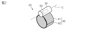
- FIG. 2 is an external view of the vibration device.
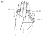
- FIG. 3 is a diagram showing a state in which the vibration device is attached to a user's finger.
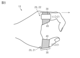
- FIG. 4 is a diagram showing an example of the direction of a force sense presented to an open hand.
- FIG. 5 is a diagram showing an example of the direction of a force sense presented to an open hand.
- FIG. 6 is a diagram showing an example of the direction of a force sense presented to an open hand.
- FIG. 7 is a diagram showing an example of the direction of a force sense presented to an open hand.
- FIG. 8 is a diagram showing an example of the direction of a force sense presented to a cupped hand.
- FIG. 1 is a schematic diagram of a force illusion presentation device.
- FIG. 2 is an external view of the vibration device.
- FIG. 3 is a diagram showing a state in which the vibration device is attached to a user's finger.
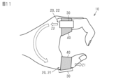
- FIG. 9 is a diagram showing an example of the direction of a force sense presented to a cupped hand.
- FIG. 10 is a diagram showing an example of the direction of a force sense presented to a cupped hand.
- FIG. 11 is a diagram showing an example of the direction of a force sense presented to a cupped hand.
- FIG. 12 is a diagram showing a state in which a vibration device according to a modified example is attached to a user's finger.
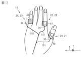
- FIG. 13 is a diagram showing a state in which a vibration device according to a modified example is attached to a user's finger.
- FIG. 14 is a diagram showing a state in which the vibration device according to the modified example is worn on the user's finger.
- the illusionary force presentation device 10 includes a first vibration device 21, a second vibration device 22, and a third vibration device 23.
- first vibration device 21, the second vibration device 22, and the third vibration device 23 may be simply referred to as vibration devices 20.
- vibration devices 20 since the three vibration devices 20 all have the same structure, the following description will be given by representing one of the vibration devices 20.
- the vibration device 20 includes a housing 30 , an accessory 40 , and a vibrating body 50 .
- the housing 30 is cylindrical with a central axis C.
- the housing 30 has a cavity inside.
- the vibrating body 50 is housed in the housing 30.
- the vibrating body 50 can generate vibrations.
- the vibrating body 50 includes a voice coil motor, a weight corresponding to each voice coil motor, and a cylindrical case that houses them.
- the weights are vibrated by a force generated when a current flows through the coil of the voice coil motor. When the weights vibrate, the case vibrates due to the vibration of the weights.
- the vibrating body 50 vibrates in a direction along the central axis C of the housing 30 by controlling the current flowing through the coil of the voice coil motor. More specifically, the vibrating body 50 is a vibrating body as described in, for example, JP 2005-190465 A.
- the accessory 40 has a first band 41 and a second band 42.
- the first band 41 is flexible and strip-like.
- One end of the first band 41 is connected to the outer peripheral surface of the housing 30.
- the first band 41 extends from the outer peripheral surface of the housing 30 in a direction perpendicular to the central axis C. In other words, the width direction of the first band 41 is parallel to the central axis C of the housing 30.
- one main surface of the first band 41 is a hook-and-loop fastener.
- the second band 42 is a flexible band. One end of the second band 42 is connected to the outer peripheral surface of the housing 30. The second band 42 extends from the outer peripheral surface of the housing 30 in the opposite direction to the first band 41. In other words, the width direction of the second band 42 is parallel to the central axis C of the housing 30, similar to the first band 41. Although not shown in the figure, one main surface of the second band 42 is a hook-and-loop fastener.
- the accessory 40 becomes cylindrical as a whole by attaching the hook-and-loop fastener portion of the second band 42 to the hook-and-loop fastener portion of the first band 41.
- the central axis of the accessory 40 is approximately parallel to the central axis C of the housing 30.
- the accessory 40 can be worn on the user's finger by wrapping the first band 41 and the second band 42 around the user's finger and attaching the hook-and-loop fastener portions of both bands to each other.
- the illusionary force presentation device 10 includes a control unit 100 and three communication cables 101.
- the control unit 100 controls the vibration pattern of the vibrating body 50 of each vibration device 20 to a specific pattern, thereby allowing the illusionary force to be presented to the user through each vibration device 20.
- the control unit 100 stores a plurality of vibration patterns for presenting a force sense.
- One of the plurality of vibration patterns is a pattern for presenting a force sense in one direction along the central axis C of the housing 30.
- the other of the plurality of vibration patterns is a pattern for presenting a force sense in the other direction along the central axis C of the housing 30. Details of the vibration pattern for presenting a force sense in a specific direction are publicly known as described in Patent Document 1 and the like, and therefore will not be described here.
- the control unit 100 may be configured as a circuit including one or more processors that execute various processes according to a computer program (software).
- the control unit 100 may also be configured as a circuit including one or more dedicated hardware circuits, such as an application specific integrated circuit (ASIC), that execute at least some of the various processes, or a combination thereof.
- the processor includes a CPU and memory such as RAM and ROM.
- the memory stores program code or instructions configured to cause the CPU to execute the processes.
- the memory i.e., computer readable medium, includes any available medium that can be accessed by a general-purpose or dedicated computer.
- the control unit 100 is equipped with a battery for driving each vibration device 20.
- Each communication cable 101 is a so-called multi-axial cable. A first end of each communication cable 101 is connected to the control unit 100. A second end of each communication cable 101 is connected to a corresponding vibration body 50. Each communication cable 101 electrically connects the control unit 100 and the vibration body 50. That is, the control unit 100 transmits a signal to each vibration device 20 via the communication cable 101. Also, a battery in the control unit 100 supplies power to each vibration device 20 via the communication cable 101.
- the first vibration device 21, the second vibration device 22, and the third vibration device 23 are each connected to the control unit 100 via the communication cable 101.
- the first vibration device 21, the second vibration device 22, and the third vibration device 23 are not connected to each other except via the communication cable 101. In other words, there is no member that directly connects the first vibration device 21, the second vibration device 22, and the third vibration device 23 to each other.
- each communication cable 101 is long enough to position the control unit 100 outside the range of the user's fingers.
- the length of each communication cable 101 is 50 cm. Therefore, the first vibration device 21 can freely change its relative position and orientation with respect to the second vibration device 22 within a range of approximately a 100 cm radius from the second vibration device 22. Note that the above 100 cm is the length of two communication cables 101.
- the second vibration device 22 can freely change its relative position and orientation with respect to the third vibration device 23 within a range of approximately a 100 cm radius from the third vibration device 23.
- the third vibration device 23 can freely change its relative position and orientation with respect to the first vibration device 21 within a range of approximately a 100 cm radius from the first vibration device 21.
- the first vibration device 21 is attached to the thumb of the user. Specifically, the first vibration device 21 is attached to the thumb by wrapping the accessory 40 of the first vibration device 21 around the proximal phalanx of the thumb.
- the second vibration device 22 is worn on one finger selected from the user's index finger, middle finger, and ring finger.
- the second vibration device 22 is worn on the user's index finger.
- the second vibration device 22 is worn on the index finger by wrapping the accessory 40 of the second vibration device 22 around the proximal phalanx of the index finger.
- the third vibration device 23 is worn on the user's middle finger, ring finger, or little finger, which is on the little finger side relative to the finger on which the second vibration device 22 is worn.
- the third vibration device 23 is worn on the user's little finger.
- the third vibration device 23 is worn on the little finger by wrapping the accessory 40 of the third vibration device 23 around the proximal phalanx of the little finger.
- the direction in which the fingers of the user are arranged from the thumb to the little finger is defined as a first direction X.
- the housing 30 of the first vibration device 21 is located on the opposite side of the first direction X with respect to the accessory 40 of the first vibration device 21.
- the housing 30 is located on the opposite side of the first direction X with respect to the accessory 40
- the center of gravity of the housing 30 is located on the opposite side of the first direction X with respect to the central axis of the cylindrical accessory 40.
- the housing 30 of the second vibration device 22 is located on the opposite side of the first direction X relative to the accessory 40 of the second vibration device 22.
- the housing 30 of the third vibration device 23 is located on the first direction X side relative to the accessory 40 of the third vibration device 23.
- the relative position and orientation of the first vibration device 21 with respect to the second vibration device 22 can be freely changed within a range of a radius of approximately 100 cm.
- the relative position and orientation of the first vibration device 21 with respect to the second vibration device 22 can be freely changed within a range of a radius of at least 25 cm with respect to the second vibration device 22.
- the second vibration device 22 can freely change its relative position and orientation with respect to the third vibration device 23 within a range of a radius of approximately 100 cm. In other words, when each vibration device 20 is not attached to the user's finger, the second vibration device 22 can freely change its relative position and orientation with respect to the third vibration device 23 within a range of a radius of at least 25 cm with respect to the third vibration device 23.
- the third vibration device 23 can freely change its relative position and orientation with respect to the first vibration device 21 within a range of a radius of approximately 100 cm with respect to the first vibration device 21. In other words, when each vibration device 20 is not worn on the user's finger, the third vibration device 23 can freely change its relative position and orientation with respect to the first vibration device 21 within a range of a radius of at least 25 cm with respect to the first vibration device 21.
- each vibration device 20 can be freely changed within the range of one hand.
- a virtual line is drawn connecting two of the three vibration devices 20 while the first vibration device 21, the second vibration device 22, and the third vibration device 23 are attached to the user's finger.
- a first virtual line L1 is drawn passing through the center of gravity of the housing 30 of the first vibration device 21 and the center of gravity of the housing 30 of the second vibration device 22.
- the third vibration device 23 does not exist on this first virtual line L1.
- a second virtual line L2 is drawn passing through the center of gravity of the housing 30 of the second vibration device 22 and the center of gravity of the housing 30 of the third vibration device 23.
- the first vibration device 21 does not exist on this second virtual line L2.
- a third virtual line L3 is drawn passing through the center of gravity of the housing 30 of the third vibration device 23 and the center of gravity of the housing 30 of the first vibration device 21.
- the second vibration device 22 does not exist on this third virtual line L3. That is, one of the first vibration device 21, the second vibration device 22, and the third vibration device 23 does not exist on the virtual line connecting the other two.
- the control unit 100 has eight vibration modes as the vibration modes of the first vibration device 21, the second vibration device 22, and the third vibration device 23. Specifically, the control unit 100 has four vibration modes in which the vibration body 50 of the second vibration device 22 and the vibration body 50 of the third vibration device 23 are vibrated, while the vibration body 50 of the first vibration device 21 is not vibrated. As the four vibration modes, the control unit 100 has a first vibration mode, a second vibration mode, a third vibration mode, and a fourth vibration mode. These first to fourth vibration modes are vibration modes preferable for presenting a force sense to a user with the user's hand open.
- each vibrating body 50 stores a pattern for presenting a force sensation in one direction or the other direction along the central axis C of the housing 30.
- the direction along the central axis C from the wrist to the fingertip is defined as the first positive direction Z1.
- the direction along the central axis C from the fingertip to the wrist is defined as the first negative direction Z2. Note that, in the following description, each vibration device 20 is described as being attached to the left hand of the user.
- the control unit 100 causes the second vibration device 22 to present a force sensation in the first positive direction Z1. Also, in the first vibration mode, the control unit 100 causes the third vibration device 23 to present a force sensation in the first positive direction Z1.
- the control unit 100 causes the third vibration device 23 to present a force sensation in the first positive direction Z1.
- the control unit 100 causes the second vibration device 22 to present a force sensation in the first negative direction Z2. Also, in the second vibration mode, the control unit 100 causes the third vibration device 23 to present a force sensation in the first negative direction Z2. In this way, by controlling the directions of the force sensations presented by the second vibration device 22 and the third vibration device 23, the user feels a force sensation as if the entire hand is moving toward the wrist when the hand is outstretched.
- the control unit 100 causes the second vibration device 22 to present a force sensation in the first negative direction Z2. Also, in the third vibration mode, the control unit 100 causes the third vibration device 23 to present a force sensation in the first positive direction Z1. In this way, by controlling the directions of the force sensations presented by the second vibration device 22 and the third vibration device 23, the user feels a force sensation as if the entire hand is rotating to the right when viewed from the back of the hand with the hand outstretched.
- the control unit 100 causes the second vibration device 22 to present a force sensation in the first positive direction Z1. Also, in the fourth vibration mode, the control unit 100 causes the third vibration device 23 to present a force sensation in the first negative direction Z2. In this way, by controlling the directions of the force sensations presented by the second vibration device 22 and the third vibration device 23, the user can feel a force sensation as if the entire hand is rotating counterclockwise when viewed from the back of the hand with the hand outstretched.
- the control unit 100 also has four vibration modes that vibrate the vibrating body 50 of the first vibration device 21 and the vibrating body 50 of the second vibration device 22, but do not vibrate the vibrating body 50 of the third vibration device 23.
- the control unit 100 has a fifth vibration mode, a sixth vibration mode, a seventh vibration mode, and an eighth vibration mode. These fifth to eighth vibration modes are preferable vibration modes for presenting a force sensation to the user when the user has their hand cupped.
- the control unit 100 causes the first vibration device 21 to present a force sensation in the first positive direction Z1. Also, in the fifth vibration mode, the control unit 100 causes the second vibration device 22 to present a force sensation in the first positive direction Z1.
- the control unit 100 causes the direction of the force sensation presented by the first vibration device 21 and the second vibration device 22 to present a force sensation in the first positive direction Z1.
- the control unit 100 causes the first vibration device 21 to present a force sensation in the first negative direction Z2. Also, in the sixth vibration mode, the control unit 100 causes the second vibration device 22 to present a force sensation in the first negative direction Z2.
- the control unit 100 causes the directions of the force sensations presented by the first vibration device 21 and the second vibration device 22 in this manner, the user feels a force sensation as if the entire hand is moving toward the wrist when the hand is curled.
- the control unit 100 causes the first vibration device 21 to present a force sensation in the first negative direction Z2. Also, in the seventh vibration mode, the control unit 100 causes the second vibration device 22 to present a force sensation in the first positive direction Z1.
- the user feels a force sensation as if the entire hand is twisted clockwise when viewed from the thumb side with the hand curled.
- the control unit 100 causes the first vibration device 21 to present a force sensation in the first positive direction Z1. Also, in the eighth vibration mode, the control unit 100 causes the second vibration device 22 to present a force sensation in the first negative direction Z2.
- the user feels a force sensation as if the entire hand is twisted counterclockwise when viewed from the thumb side with the hand curled.
- each vibration device 20 can be attached to any finger desired by the user.
- the distance between the tip of the thumb and the tip of the little finger is within 25 cm at most. Therefore, no matter which finger each vibration device 20 is attached to, the movement of the user's fingers is unlikely to be restricted.
- the user can specify the fingers on which each vibration device 20 is attached. Furthermore, since the movement of the user's fingers is not restricted, the pose of the fingers can be specified in a predetermined shape. In this way, various variations occur in the fingers on which each vibration device 20 is attached and the poses of the fingers, so that various variations in force sensations can be presented to the user.
- the first vibration device 21, the second vibration device 22, and the third vibration device 23 are each connected to the control unit 100 via the communication cable 101. Therefore, it is unlikely that only one of the vibration devices 20 will be lost.
- the first vibration device 21, the second vibration device 22, and the third vibration device 23 are not connected to each other except via the communication cable 101. With this configuration, when each vibration device 20 is attached to a finger, there is no interference from other components, making it easy to attach each vibration device 20.
- the first vibration device 21 is attached to the thumb of the user.
- the thumb has a different direction of movement compared to the other fingers. Therefore, by attaching the first vibration device 21 to the thumb, the variety of directions of the force sensation that can be presented to the user is increased.
- the second vibration device 22 is attached to the index finger of the user.
- the third vibration device 23 is attached to the little finger of the user. That is, in the above embodiment, the vibration device 20 is attached to the farthest finger of the four fingers from the index finger to the little finger. This configuration makes it easier for the user to perceive a force sensation over the entire hand.
- the housing 30 of the first vibration device 21 is located on the opposite side of the first direction X with respect to the accessory 40 of the first vibration device 21.
- the housing 30 of the second vibration device 22 is located on the opposite side of the first direction X with respect to the accessory 40 of the second vibration device 22.
- the housing 30 of the third vibration device 23 is located on the first direction X side with respect to the accessory 40 of the third vibration device 23.
- the control unit 100 has a vibration mode that vibrates the vibrating body 50 of the second vibration device 22 and the vibrating body 50 of the third vibration device 23, but does not vibrate the vibrating body 50 of the first vibration device 21.
- the control unit 100 has first to fourth vibration modes.
- the force illusion presentation device 10 can present a force sensation to a user's open hand that moves the hand toward the fingertips or wrist.
- the force illusion presentation device 10 can present a force sensation to a user's open hand that rotates the hand left and right.
- the control unit 100 has a vibration mode in which the vibrating body 50 of the first vibration device 21 and the vibrating body 50 of the second vibration device 22 are vibrated, while the control unit 100 does not vibrate the vibrating body 50 of the third vibration device 23.
- the control unit 100 has the fifth vibration mode to the eighth vibration mode.
- the illusionary force presentation device 10 can present a force sensation to the user's hand in a curled state, such that the hand moves toward the wrist or in the opposite direction to the wrist.
- the illusionary force presentation device 10 can present a force sensation to the user's hand in a curled state. In this way, with the above configuration, the user can perceive a force sensation when the hand is curled. Therefore, the user can feel the above-mentioned force sensation even when the user is holding another member in the hand.
- the shape of the housing 30 is not limited to the example of the above embodiment.
- the housing 30 may be spherical or rectangular. It is sufficient that the housing 30 is capable of housing the vibrating body 50 therein.
- the three vibration devices 20 have the same configuration, but each vibration device 20 may have a different configuration.
- the dimensions of the accessory 40 of the first vibration device 21 may be larger than the dimensions of the accessory 40 of the other vibration devices 20. In this way, if the finger on which each vibration device 20 is worn is specified, the size and shape of the accessory 40 can be designed according to the size of the finger.
- the finger on which each vibration device 20 is to be worn is specified, letters and symbols indicating the finger on which it should be worn may be attached to the housing 30 or the accessory 40. Specifically, for example, the letters “thumb” may be attached to the accessory 40 of the first vibration device 21. If such letters, symbols, etc. are attached, the vibration device 20 is a "vibration device 20 worn on the thumb.”
- the force illusion presentation device 10 may further include a member connecting the three vibration devices 20 to each other.
- the force illusion presentation device 10 may include a string-like member connecting each vibration device 20 to each other. With this configuration, each vibration device 20 is less likely to be lost. However, the member connecting the three vibration devices 20 to each other must be long enough not to restrict the positional relationship and orientation of each vibration device 20 within a radius of 25 cm.
- the configuration of the accessory 40 is not limited to that of the above embodiment.
- the accessory 40 may be a ring-shaped member made of a material such as synthetic resin or metal.
- the accessory 40 may be of any shape or material as long as it can be worn on the user's finger and can transmit the vibrations of the vibrating body 50 to the user's finger.
- each vibration device 20 may further include an additional vibration body capable of vibrating in a direction different from that of the vibration body 50 in the above embodiment.
- the different direction is a direction intersecting the central axis C of the housing 30.
- the vibration device 20 further includes a vibration body capable of vibrating in a direction perpendicular to the pads of the user's fingers, the user may be able to perceive a force sensation similar to fanning the hand when the hand is open.
- the configuration of the vibrating body 50 is not limited to the above configuration.
- the vibrating body 50 may use vibration generated by a motor, or may have a piezoelectric element.
- control unit 100 may vibrate the vibrating body 50 with a vibration pattern that generates a tactile sensation such as a rough tactile sensation or an uneven tactile sensation.
- a vibration pattern that generates a tactile sensation
- the above-mentioned tactile sensation can be presented to the user by, for example, adjusting the strength distribution of the resistance generated by the vibrating body 50.
- the illusionary force presentation device 10 does not need to include a communication cable 101.
- each vibration device 20 only needs to have a built-in battery or the like.
- the first vibration device 21 may be attached to a finger other than the thumb.
- the second vibration device 22 may be attached to a finger other than the index finger.
- the third vibration device 23 may be attached to a finger other than the little finger.
- the first vibration device 21, the second vibration device 22, and the third vibration device 23 may be attached to the same finger.
- the attachment position of each vibration device 20 on the finger is not limited to the example of the above embodiment.
- the attachment position of the accessory 40 of each vibration device 20 is not limited to the proximal phalangeal part of the finger.
- the first vibration device 21 may be attached to the proximal phalangeal part of the finger, the second vibration device 22 to the middle phalangeal part of the finger, and the third vibration device 23 to the distal phalangeal part of the finger, and the attachment position may be different for each vibration device 20.
- each vibration device 20 when each vibration device 20 is attached to the user's finger, one of the first vibration device 21, the second vibration device 22, and the third vibration device 23 may be present on a virtual straight line connecting the other two.
- the position of the housing 30 relative to the accessory 40 when the accessory 40 is worn on a finger is not limited to the example in the above embodiment. 12
- the direction from the pad side to the dorsal side of the user's fingers when the user's hand is open is defined as the second direction Y.
- the second direction Y coincides with the direction from the palm side to the back side of the user's hand when the user's hand is open.
- the housing 30 of the first vibration device 21 is located on the second direction Y side with respect to the accessory 40 of the first vibration device 21.
- the second vibration device 22 is worn on the index finger of the user.
- the housing 30 of the second vibration device 22 is located on the second direction Y side relative to the accessory 40 of the second vibration device 22.
- the housing 30 of the first vibration device 21 when the first vibration device 21 is worn on the user's finger, the housing 30 of the first vibration device 21 is located on the second direction Y side relative to the accessory 40 of the first vibration device 21. In this way, when the vibration device 20 is worn on the user's finger, the housing 30 of multiple vibration devices 20 may be located on the second direction Y side relative to the accessory 40.
- the third vibration device 23 is worn on the little finger of the user.
- the housing 30 of the third vibration device 23 is located on the second direction Y side with respect to the accessory 40 of the third vibration device 23.
- the housing 30 of each vibration device 20 may be positioned on the opposite side of the accessory 40 from the second direction Y.
- the positional relationship between the housing 30 and the accessory 40 is not limited to the example described above.
- a force illusion presentation device comprising a first vibration device, a second vibration device, a third vibration device, and a control unit that controls the first vibration device, the second vibration device, and the third vibration device, each of which has a housing, a vibrating body contained in the housing and capable of generating vibrations, and an ornament connected to the housing and worn on a user's finger, and the control unit is capable of presenting a force illusion to the user by controlling the vibration pattern of the vibrating body, and the first vibration device is capable of freely changing its relative position and orientation with respect to the second vibration device within a radius of at least 25 cm from the second vibration device, the second vibration device is capable of freely changing its relative position and orientation with respect to the third vibration device within a radius of at least 25 cm from the third vibration device, and the third vibration device is capable of freely changing its relative position and orientation with respect to the first vibration device within a radius of at least 25 cm
- the first vibration device, the second vibration device, and the third vibration device are each connected to the control unit via a communication cable, and the first vibration device, the second vibration device, and the third vibration device are not connected to each other except via the communication cable.
- the illusionary force presentation device is
- [4] The illusionary force presentation device according to any one of [1] to [3], wherein the first vibration device is attached to the thumb of the user, the second vibration device is attached to one finger selected from the index finger, middle finger, and ring finger of the user, and the third vibration device is attached to one of the middle finger, ring finger, and little finger of the user that is on the little finger side relative to the finger on which the second vibration device is attached.
- C central axis
- X first direction
- Y second direction
- 10 force illusion presentation device
- 20 vibration device
- 21 first vibration device
- 22 second vibration device
- 23 third vibration device
- 30 housing
- 40 accessory
- 50 vibration body
- 100 control unit
- 101 communication cable
Landscapes
- Engineering & Computer Science (AREA)
- General Engineering & Computer Science (AREA)
- Theoretical Computer Science (AREA)
- Human Computer Interaction (AREA)
- Physics & Mathematics (AREA)
- General Physics & Mathematics (AREA)
- Power Engineering (AREA)
- User Interface Of Digital Computer (AREA)
Priority Applications (3)
| Application Number | Priority Date | Filing Date | Title |
|---|---|---|---|
| CN202480025115.8A CN120936972A (zh) | 2023-04-14 | 2024-04-10 | 错觉力觉呈现装置 |
| JP2025513986A JPWO2024214741A1 (https=) | 2023-04-14 | 2024-04-10 | |
| US19/350,196 US20260029851A1 (en) | 2023-04-14 | 2025-10-06 | Illusionary force sense presentation apparatus |
Applications Claiming Priority (2)
| Application Number | Priority Date | Filing Date | Title |
|---|---|---|---|
| JP2023066661 | 2023-04-14 | ||
| JP2023-066661 | 2023-04-14 |
Related Child Applications (1)
| Application Number | Title | Priority Date | Filing Date |
|---|---|---|---|
| US19/350,196 Continuation US20260029851A1 (en) | 2023-04-14 | 2025-10-06 | Illusionary force sense presentation apparatus |
Publications (1)
| Publication Number | Publication Date |
|---|---|
| WO2024214741A1 true WO2024214741A1 (ja) | 2024-10-17 |
Family
ID=93059439
Family Applications (1)
| Application Number | Title | Priority Date | Filing Date |
|---|---|---|---|
| PCT/JP2024/014547 Ceased WO2024214741A1 (ja) | 2023-04-14 | 2024-04-10 | 錯力覚提示装置 |
Country Status (4)
| Country | Link |
|---|---|
| US (1) | US20260029851A1 (https=) |
| JP (1) | JPWO2024214741A1 (https=) |
| CN (1) | CN120936972A (https=) |
| WO (1) | WO2024214741A1 (https=) |
Citations (5)
| Publication number | Priority date | Publication date | Assignee | Title |
|---|---|---|---|---|
| JP2000501033A (ja) * | 1995-11-30 | 2000-02-02 | ヴァーチャル テクノロジーズ インコーポレイテッド | 触覚をフィードバックする人間/機械インターフェース |
| WO2009035100A1 (ja) * | 2007-09-14 | 2009-03-19 | National Institute Of Advanced Industrial Science And Technology | バーチャルリアリティ環境生成装置及びコントローラ装置 |
| WO2020090943A1 (ja) * | 2018-10-30 | 2020-05-07 | Cyberdyne株式会社 | インタラクティブ情報伝達システム及びインタラクティブ情報伝達方法並びに情報伝達システム |
| CN115129153A (zh) * | 2022-06-24 | 2022-09-30 | 东南大学 | 一种基于加权幅频振动叠加的指尖触觉反馈装置 |
| JP2023043996A (ja) * | 2021-09-17 | 2023-03-30 | 株式会社Jvcケンウッド | 触感生成装置、触感生成方法及びプログラム |
-
2024
- 2024-04-10 CN CN202480025115.8A patent/CN120936972A/zh active Pending
- 2024-04-10 WO PCT/JP2024/014547 patent/WO2024214741A1/ja not_active Ceased
- 2024-04-10 JP JP2025513986A patent/JPWO2024214741A1/ja active Pending
-
2025
- 2025-10-06 US US19/350,196 patent/US20260029851A1/en active Pending
Patent Citations (5)
| Publication number | Priority date | Publication date | Assignee | Title |
|---|---|---|---|---|
| JP2000501033A (ja) * | 1995-11-30 | 2000-02-02 | ヴァーチャル テクノロジーズ インコーポレイテッド | 触覚をフィードバックする人間/機械インターフェース |
| WO2009035100A1 (ja) * | 2007-09-14 | 2009-03-19 | National Institute Of Advanced Industrial Science And Technology | バーチャルリアリティ環境生成装置及びコントローラ装置 |
| WO2020090943A1 (ja) * | 2018-10-30 | 2020-05-07 | Cyberdyne株式会社 | インタラクティブ情報伝達システム及びインタラクティブ情報伝達方法並びに情報伝達システム |
| JP2023043996A (ja) * | 2021-09-17 | 2023-03-30 | 株式会社Jvcケンウッド | 触感生成装置、触感生成方法及びプログラム |
| CN115129153A (zh) * | 2022-06-24 | 2022-09-30 | 东南大学 | 一种基于加权幅频振动叠加的指尖触觉反馈装置 |
Also Published As
| Publication number | Publication date |
|---|---|
| CN120936972A (zh) | 2025-11-11 |
| JPWO2024214741A1 (https=) | 2024-10-17 |
| US20260029851A1 (en) | 2026-01-29 |
Similar Documents
| Publication | Publication Date | Title |
|---|---|---|
| US10894204B2 (en) | Exo-tendon motion capture glove device with haptic grip response | |
| Lindeman et al. | Wearable vibrotactile systems for virtual contact and information display | |
| US10510225B2 (en) | Bendable electronic device apparatus and methods | |
| JP6598232B2 (ja) | 可撓性を有するように取り付けられた触覚出力装置を有するウェアラブル装置 | |
| US10583359B2 (en) | Systems and methods for providing haptic effects related to touching and grasping a virtual object | |
| US6279163B1 (en) | Musical instrument practice glove | |
| KR101578345B1 (ko) | 역감을 재생하는 장치 | |
| WO2017043610A1 (ja) | 情報処理装置、方法およびコンピュータプログラム | |
| US11422624B2 (en) | Hand interface device utilizing haptic force gradient generation via the alignment of fingertip haptic units | |
| JP2000501033A (ja) | 触覚をフィードバックする人間/機械インターフェース | |
| CN207301976U (zh) | 一种数据手套及vr系统 | |
| EP3598272A1 (en) | Trigger button for haptic controller | |
| JP7704223B2 (ja) | 力覚提示装置 | |
| JP6780559B2 (ja) | 触感提供装置、及び、触感提供システム | |
| WO2024214741A1 (ja) | 錯力覚提示装置 | |
| Regenbrecht et al. | Virtual reality aided assembly with directional vibro-tactile feedback | |
| CN112867979B (zh) | 触觉呈现装置和触觉呈现控制方法 | |
| JP2018505409A (ja) | 力測定メカニズム | |
| CN209044517U (zh) | 手部动作捕获装置 | |
| KR102819674B1 (ko) | 미세 촉감자극 발생장치 | |
| JP7722471B2 (ja) | ハプティクス装置 | |
| JP7401992B2 (ja) | 力覚提示装置 | |
| WO2015045755A1 (ja) | 触力覚提示装置、情報端末、触力覚提示方法、およびコンピュータ読み取り可能な記録媒体 | |
| JPWO2024214741A5 (https=) | ||
| WO2024177095A1 (ja) | 錯触力覚発生装置 |
Legal Events
| Date | Code | Title | Description |
|---|---|---|---|
| 121 | Ep: the epo has been informed by wipo that ep was designated in this application |
Ref document number: 24788765 Country of ref document: EP Kind code of ref document: A1 |
|
| ENP | Entry into the national phase |
Ref document number: 2025513986 Country of ref document: JP Kind code of ref document: A |
|
| WWE | Wipo information: entry into national phase |
Ref document number: 2025513986 Country of ref document: JP |
|
| NENP | Non-entry into the national phase |
Ref country code: DE |
|
| 122 | Ep: pct application non-entry in european phase |
Ref document number: 24788765 Country of ref document: EP Kind code of ref document: A1 |