WO2024214571A1 - 酸性ガス回収システムおよび酸性ガスの回収方法 - Google Patents
酸性ガス回収システムおよび酸性ガスの回収方法 Download PDFInfo
- Publication number
- WO2024214571A1 WO2024214571A1 PCT/JP2024/013064 JP2024013064W WO2024214571A1 WO 2024214571 A1 WO2024214571 A1 WO 2024214571A1 JP 2024013064 W JP2024013064 W JP 2024013064W WO 2024214571 A1 WO2024214571 A1 WO 2024214571A1
- Authority
- WO
- WIPO (PCT)
- Prior art keywords
- gas
- heating medium
- acid gas
- flow path
- acidic gas
- Prior art date
- Legal status (The legal status is an assumption and is not a legal conclusion. Google has not performed a legal analysis and makes no representation as to the accuracy of the status listed.)
- Ceased
Links
Images




Classifications
-
- B—PERFORMING OPERATIONS; TRANSPORTING
- B01—PHYSICAL OR CHEMICAL PROCESSES OR APPARATUS IN GENERAL
- B01D—SEPARATION
- B01D53/00—Separation of gases or vapours; Recovering vapours of volatile solvents from gases; Chemical or biological purification of waste gases, e.g. engine exhaust gases, smoke, fumes, flue gases, aerosols
- B01D53/02—Separation of gases or vapours; Recovering vapours of volatile solvents from gases; Chemical or biological purification of waste gases, e.g. engine exhaust gases, smoke, fumes, flue gases, aerosols by adsorption, e.g. preparative gas chromatography
- B01D53/04—Separation of gases or vapours; Recovering vapours of volatile solvents from gases; Chemical or biological purification of waste gases, e.g. engine exhaust gases, smoke, fumes, flue gases, aerosols by adsorption, e.g. preparative gas chromatography with stationary adsorbents
- B01D53/0407—Constructional details of adsorbing systems
- B01D53/0438—Cooling or heating systems
-
- B—PERFORMING OPERATIONS; TRANSPORTING
- B01—PHYSICAL OR CHEMICAL PROCESSES OR APPARATUS IN GENERAL
- B01D—SEPARATION
- B01D53/00—Separation of gases or vapours; Recovering vapours of volatile solvents from gases; Chemical or biological purification of waste gases, e.g. engine exhaust gases, smoke, fumes, flue gases, aerosols
- B01D53/02—Separation of gases or vapours; Recovering vapours of volatile solvents from gases; Chemical or biological purification of waste gases, e.g. engine exhaust gases, smoke, fumes, flue gases, aerosols by adsorption, e.g. preparative gas chromatography
- B01D53/04—Separation of gases or vapours; Recovering vapours of volatile solvents from gases; Chemical or biological purification of waste gases, e.g. engine exhaust gases, smoke, fumes, flue gases, aerosols by adsorption, e.g. preparative gas chromatography with stationary adsorbents
-
- B—PERFORMING OPERATIONS; TRANSPORTING
- B01—PHYSICAL OR CHEMICAL PROCESSES OR APPARATUS IN GENERAL
- B01D—SEPARATION
- B01D53/00—Separation of gases or vapours; Recovering vapours of volatile solvents from gases; Chemical or biological purification of waste gases, e.g. engine exhaust gases, smoke, fumes, flue gases, aerosols
- B01D53/02—Separation of gases or vapours; Recovering vapours of volatile solvents from gases; Chemical or biological purification of waste gases, e.g. engine exhaust gases, smoke, fumes, flue gases, aerosols by adsorption, e.g. preparative gas chromatography
- B01D53/04—Separation of gases or vapours; Recovering vapours of volatile solvents from gases; Chemical or biological purification of waste gases, e.g. engine exhaust gases, smoke, fumes, flue gases, aerosols by adsorption, e.g. preparative gas chromatography with stationary adsorbents
- B01D53/0462—Temperature swing adsorption
-
- C—CHEMISTRY; METALLURGY
- C01—INORGANIC CHEMISTRY
- C01B—NON-METALLIC ELEMENTS; COMPOUNDS THEREOF; METALLOIDS OR COMPOUNDS THEREOF NOT COVERED BY SUBCLASS C01C
- C01B32/00—Carbon; Compounds thereof
- C01B32/50—Carbon dioxide
-
- B—PERFORMING OPERATIONS; TRANSPORTING
- B01—PHYSICAL OR CHEMICAL PROCESSES OR APPARATUS IN GENERAL
- B01D—SEPARATION
- B01D2253/00—Adsorbents used in seperation treatment of gases and vapours
- B01D2253/30—Physical properties of adsorbents
- B01D2253/34—Specific shapes
- B01D2253/342—Monoliths
- B01D2253/3425—Honeycomb shape
-
- B—PERFORMING OPERATIONS; TRANSPORTING
- B01—PHYSICAL OR CHEMICAL PROCESSES OR APPARATUS IN GENERAL
- B01D—SEPARATION
- B01D2257/00—Components to be removed
- B01D2257/50—Carbon oxides
- B01D2257/504—Carbon dioxide
-
- B—PERFORMING OPERATIONS; TRANSPORTING
- B01—PHYSICAL OR CHEMICAL PROCESSES OR APPARATUS IN GENERAL
- B01D—SEPARATION
- B01D2258/00—Sources of waste gases
- B01D2258/06—Polluted air
-
- B—PERFORMING OPERATIONS; TRANSPORTING
- B01—PHYSICAL OR CHEMICAL PROCESSES OR APPARATUS IN GENERAL
- B01D—SEPARATION
- B01D2259/00—Type of treatment
- B01D2259/40—Further details for adsorption processes and devices
- B01D2259/40083—Regeneration of adsorbents in processes other than pressure or temperature swing adsorption
- B01D2259/40088—Regeneration of adsorbents in processes other than pressure or temperature swing adsorption by heating
-
- Y—GENERAL TAGGING OF NEW TECHNOLOGICAL DEVELOPMENTS; GENERAL TAGGING OF CROSS-SECTIONAL TECHNOLOGIES SPANNING OVER SEVERAL SECTIONS OF THE IPC; TECHNICAL SUBJECTS COVERED BY FORMER USPC CROSS-REFERENCE ART COLLECTIONS [XRACs] AND DIGESTS
- Y02—TECHNOLOGIES OR APPLICATIONS FOR MITIGATION OR ADAPTATION AGAINST CLIMATE CHANGE
- Y02C—CAPTURE, STORAGE, SEQUESTRATION OR DISPOSAL OF GREENHOUSE GASES [GHG]
- Y02C20/00—Capture or disposal of greenhouse gases
- Y02C20/40—Capture or disposal of greenhouse gases of CO2
Definitions
- the present invention relates to an acid gas recovery system and a method for recovering acid gas.
- the main object of the present invention is to provide an acid gas recovery system and an acid gas recovery method that can recover acid gas with reduced energy consumption.
- An acidic gas recovery system includes an acidic gas adsorption section, a storage section, a heating medium supply section, and a recovery section.
- the acidic gas adsorption section includes an acidic gas adsorbent.
- the acidic gas adsorbent is capable of adsorbing acidic gas contained in a gas to be treated and is capable of desorbing the adsorbed acidic gas.
- the storage section includes a flow path to which the gas to be treated is supplied.
- the storage section stores the acidic gas adsorption section such that the acidic gas adsorption section is located in the flow path.
- the heating medium supply section is capable of supplying a heating medium having a pressure exceeding atmospheric pressure to the flow path.
- the recovery section is capable of recovering a recovered gas from the storage section.
- the recovered gas includes a heating medium that has passed through the acidic gas adsorption section and acidic gas desorbed from the acidic gas adsorbent.
- the acidic gas recovery system described in [1] above may be configured so that the temperature difference specific heat coefficient ⁇ Cp/ ⁇ T of the heating medium satisfies the following formula (1): ⁇ Cp/ ⁇ T ⁇ 0.039 (J/(mol ⁇ K 2 ))...(1) ⁇ Cp: the difference between the constant pressure molar specific heat a at the inlet of the flow path of the heating medium supplied and the constant pressure molar specific heat b of the recovery gas discharged from the flow path (constant pressure molar specific heat a - constant pressure molar specific heat b) (unit: J / (mol K)), ⁇ T: the difference between the temperature a of the heating medium supplied at the inlet of the flow path and the temperature b of the recovered gas discharged from the flow path (gas
- the heating medium supply unit may include a pressurizing device capable of pressurizing the heating medium.
- the recovery section may include a storage tank capable of storing the recovered gas.
- the acid gas recovery system according to [4] may further include a return unit that is capable of returning at least a portion of the recovered gas stored in the storage tank from the storage tank to the heating medium supply unit as the heating medium.
- the storage tank may be capable of separating a portion of the heating medium from the recovered gas.
- a method for recovering an acidic gas according to another aspect of the present invention includes an adsorption step and a desorption step.
- a gas to be treated containing an acidic gas is supplied to a flow path of a container in which an acidic gas adsorption section containing an acidic gas adsorbent is disposed, so that the acidic gas is adsorbed by the acidic gas adsorbent.
- a heating medium having a pressure exceeding atmospheric pressure is supplied to the flow path to heat the acidic gas adsorption section to a predetermined desorption temperature, so that the acidic gas is desorbed from the acidic gas adsorbent.
- a recovery gas containing the heating medium that has passed through the acidic gas adsorption section and the acidic gas desorbed from the acidic gas adsorbent is recovered from the flow path.
- acid gas can be recovered with reduced energy consumption.
- FIG. 1A is a schematic diagram of an acid gas recovery system according to one embodiment of the present invention.
- FIG. 1B is a schematic diagram of an acid gas recovery system according to another embodiment of the present invention.
- FIG. 2 is a schematic diagram of the acid gas adsorption unit included in the acid gas recovery system of FIG. 1A.
- FIG. 3 is a schematic perspective view of an acid gas adsorption unit provided in an acid gas recovery system according to yet another embodiment of the present invention.
- FIG. 4 is a central cross-sectional view of the acid gas adsorption section of FIG.
- FIG. 1A is a schematic diagram of an acid gas recovery system according to one embodiment of the present invention
- Figure 1B is a schematic diagram of an acid gas recovery system according to another embodiment of the present invention.
- the illustrated acidic gas recovery system 100 includes an acidic gas adsorption section 1, a storage section 2, a heating medium supply section 6, and a recovery section 4.
- the acidic gas adsorption section 1 includes an acidic gas adsorbent.
- the acidic gas adsorbent can adsorb the acidic gas contained in the gas to be treated and can desorb the adsorbed acidic gas.
- the storage section 2 includes a flow path 21 to which the gas to be treated is supplied.
- the storage section 2 has a cylindrical shape extending in the supply direction of the gas to be treated.
- the storage section 2 accommodates the acidic gas adsorption section 1 so that the acidic gas adsorption section 1 is located in the flow path 21.
- the heating medium supply section 6 can supply a heating medium having a pressure exceeding atmospheric pressure (0.1 MPaA (absolute pressure)) to the flow path 21.
- the recovery section 4 can recover the recovered gas from the storage section 2.
- the recovered gas includes the heating medium that has passed through the acidic gas adsorption section 1 and the acidic gas desorbed from the acidic gas adsorbent.
- the acidic gas recovery system can sequentially perform the adsorption process and the desorption process, and can recover the pressurized acidic gas.
- the acidic gas adsorbent of the acidic gas adsorption unit located in the flow path can adsorb the acidic gas.
- the heating medium supply unit can supply a heating medium having a pressure exceeding atmospheric pressure (0.1 MPaA) to the flow path.
- the acidic gas adsorption unit is efficiently heated to a predetermined desorption temperature by the heating medium, and as a result, the acidic gas adsorbent is efficiently heated. This allows the acidic gas to be desorbed from the acidic gas adsorbent. Therefore, the energy required for desorption of the acidic gas can be significantly suppressed.
- the recovery section can recover the recovery gas containing the heating medium that has passed through the acidic gas adsorption section and the acidic gas desorbed from the acidic gas adsorbent from the storage section. Therefore, the acidic gas can be recovered together with the heating medium with energy saving.
- the recovery gas contains the heating medium that is supplied with a pressure exceeding atmospheric pressure, and is therefore pressurized above atmospheric pressure (0.1 MPaA).
- the recovery section can recover the acidic gas in a pressurized state (in other words, a state having a pressure exceeding atmospheric pressure) together with the heating medium. Since such acidic gas is in a pressurized state, it can be supplied to various devices with excellent energy efficiency and can be effectively used with energy saving.
- the container 2 has a first inlet 22 , a first outlet 23 , a second inlet 24 , and a second outlet 25 .
- the first inlet 22 is located at an upstream end in the supply direction of the gas to be treated in the accommodation section 2.
- the first inlet 22 allows the gas to be treated to pass through in the adsorption step.
- the first outlet 23 is located at a downstream end in the supply direction of the gas to be treated in the storage section 2.
- the first outlet 23 allows the treated gas, which has passed through the acidic gas adsorption section 1 in the adsorption step and has a reduced acidic gas concentration, to pass therethrough.
- the second inlet 24 and the second outlet 25 are located between the first inlet 22 and the first outlet 23.
- the second inlet 24 and the second outlet 25 are typically provided on a side wall of the storage section 2.
- the second inlet 24 allows the heating medium to pass through in the desorption process.
- the second outlet 25 allows the recovery gas to pass through in the desorption process.
- the acidic gas recovery system 100 further includes a first valve 51 and a second valve 52.
- Each of the first valve 51 and the second valve 52 can open and close the flow path 21.
- the first valve 51 is located upstream of the acidic gas adsorption unit 1 in the supply direction of the gas to be treated.
- the second valve 52 is located on the opposite side of the first valve 51 with respect to the acidic gas adsorption unit 1.
- the first valve 51 and the second valve 52 partition the flow path 21 to define the storage space S in which the acidic gas adsorption unit 1 is located.
- Each of the second inlet 24 and the second outlet 25 is located between the first valve 51 and the second valve 52.
- the heating medium supply unit 6 can supply a pressurized heating medium to the storage space S via the second inlet 24. According to this configuration, in the desorption step, when the first valve and the second valve are closed and the heating medium supply unit supplies the pressurized heating medium to the storage space, the storage space can be sufficiently pressurized, and therefore the recovery unit can stably recover the sufficiently pressurized recovery gas through the second outlet.
- the first valve 51 may be, for example, a ball valve, a gate valve, or a butterfly valve.
- the first valve 51 is preferably a butterfly valve.
- the second valve 52 is described in the same manner as the first valve 51.
- the configuration of the heating medium supply unit 6 is not particularly limited as long as it can supply a heating medium having a pressure exceeding atmospheric pressure to the flow path 21.
- the pressure of the heating medium can be arbitrarily and appropriately adjusted so that the pressure of the flow path 21 (representatively, the storage space S) to which the heating medium is supplied is within the range described below.
- the heating medium supply unit 6 includes a pressurizing device 62 capable of pressurizing the heating medium.
- the heating medium supply unit includes a pressurizing device, the heating medium can be stably pressurized to a desired pressure.
- the pressurizing device 62 is typically capable of pumping the heating medium.
- the pressurizing device 62 may have any appropriate configuration. Examples of the pressurizing device 62 include a fan, a blower, and a compressor.
- the heating medium supply unit 6 in the illustrated example includes a heating device 63 , a connection line 64 , and a supply line 61 in addition to a pressure device 62 .
- the heating device 63 is typically capable of heating a heating medium.
- the heating device 63 is supplied with a heating medium pressurized by the pressurizing device 62.
- the heating device 63 may have any appropriate configuration. Examples of the heating device 63 include a heater and a heat exchanger.
- the connection line 64 is typically a pipe capable of supplying the heating medium pressurized by the pressurizing device 62 to the heating device 63. An upstream end of the connection line 64 in the supply direction of the heating medium is connected to the pressurizing device 62.
- a downstream end of the connection line 64 in the supply direction of the heating medium is connected to the heating device 63.
- the supply line 61 is typically a pipe through which a heated and pressurized heating medium can pass.
- An upstream end of the supply line 61 in the direction in which the heating medium passes is connected to a heating device 63.
- a downstream end of the supply line 61 in the direction in which the heating medium passes is connected to a side wall of the storage unit 2 so as to communicate with the second inlet 24. This allows the heating medium supply unit to stably supply the pressurized heating medium to the storage space of the storage unit.
- the recovery section 4 includes a storage tank 42.
- the storage tank 42 is typically capable of storing the recovery gas in a pressurized state.
- the storage tank 42 may have any suitable configuration.
- the storage tank 42 is typically configured to be capable of separating a portion of the heating medium from the collected gas stored therein.
- the inside of the storage tank 42 is pressurized higher than atmospheric pressure (0.1 MPaA), so that a portion of the heating medium can be drained (liquefied). Therefore, a portion of the drained heating medium accumulates at the bottom of the storage tank 42. Therefore, the self-pressure of the collected gas can be effectively used for partial separation of the heating medium.
- the recovery section 4 in the illustrated example includes a recovery line 41 and a discharge line 43 in addition to a storage tank 42 .
- the recovery line 41 is typically a pipe through which the recovery gas discharged from the second outlet 25 can pass.
- the upstream end of the recovery line 41 in the passage direction of the recovery gas is connected to the side wall of the storage unit 2 so as to communicate with the second outlet 25.
- the downstream end of the recovery line 41 in the passage direction of the recovery gas is connected to the storage tank 42.
- the recovery line 41 may be provided with a valve capable of adjusting the flow rate of the recovery gas. This makes it possible to suitably adjust the internal pressure of the storage space in the desorption step, and as a result, to recover a recovery gas having a desired pressure.
- the discharge line 43 is typically a pipe capable of discharging a portion of the heating medium separated in the storage tank 42.
- An upstream end of the discharge line 43 in the discharge direction of the recovered gas is connected to the bottom of the storage tank 42. This makes it possible to remove impurities from the acid gas recovery system.
- the acid gas recovery system 100 further includes a return section 3.
- the return unit 3 can return at least a portion of the recovered gas stored in the storage tank 42 from the storage tank 42 to the heating medium supply unit 6 as a heating medium. Therefore, the self-pressure of the recovered gas can be effectively used to pressurize the heating medium in the heating medium supply unit. As a result, the energy required to drive the pressurizing device 62 can be reduced, or a heating medium having a pressure exceeding atmospheric pressure can be supplied to the flow path without the pressurizing device 62. Therefore, the acid gas recovery system 100 can be operated with reduced energy.
- the return unit 3 can return at least a part of the recovered gas as a heating medium from the storage tank 42 to the pressurizing device 62.
- the return unit 3 typically includes a return line 31.
- the return line 31 is typically a pipe through which the recovered gas returned as a heating medium can pass.
- the upstream end of the return line 31 in the return direction of the recovered gas is connected to a storage tank 42.
- the downstream end of the return line 31 in the return direction of the recovered gas is connected to a pressurizing device 62.
- the pressurizing device 62 is connected to the storage tank 42 as a supply source of the heating medium via the return line 31, but the acidic gas recovery system 100 is not limited to this.
- the acidic gas recovery system 100 shown in Fig. 1B does not include the return section 3.
- the recovered gas is not returned from the storage tank 42 to the pressurizing device 62, and the heating medium is supplied from a supply source other than the storage tank 42.
- the acid gas recovery system 100 can be configured without the pressurizing device 62.
- a heating medium e.g., steam
- This can simplify the acid gas recovery system.
- acidic gases contained in the gas to be treated in the acidic gas recovery system include carbon dioxide (CO 2 ), hydrogen sulfide, sulfur dioxide, nitrogen dioxide, dimethyl sulfide (DMS), and hydrogen chloride.
- the acidic gas is carbon dioxide (CO 2 )
- the gas to be treated is a CO 2- containing gas.
- the CO 2- containing gas may contain nitrogen in addition to CO 2.
- the CO 2- containing gas is typically air (atmosphere).
- the CO 2 concentration in the CO 2- containing gas before being supplied to the acidic gas recovery system is, for example, 100 ppm (volume basis) or more and 2 vol% or less.
- the heating medium supplied by the heating medium supply unit may be, for example, steam or CO2 .
- the heating medium may be used alone or in combination.
- the heating medium is preferably CO2 .
- the acid gas and the heating medium are carbon dioxide (CO 2 )
- CO 2 carbon dioxide
- the acidic gas adsorbent contained in the acidic gas adsorption section is a carbon dioxide adsorbent.
- the carbon dioxide adsorbent any suitable compound capable of adsorbing and desorbing CO 2 may be employed.
- carbon dioxide adsorbents examples include nitrogen-containing compounds; alkali compounds such as sodium hydroxide and potassium hydroxide; carbonates such as calcium carbonate and potassium carbonate; bicarbonates such as calcium bicarbonate and potassium bicarbonate; metal-organic frameworks (MOFs) such as MOF-74, MOF-200, and MOF-210; ionic liquids; deep eutectic solvents; oxides such as cerium oxide and iron oxide; zeolites; activated carbon; and nitrogen-doped carbon.
- These carbon dioxide adsorbents may be used alone or in combination. Of these carbon dioxide adsorbents, preferred are nitrogen-containing compounds and ionic liquids.
- nitrogen-containing compound examples include primary amines such as monoethanolamine and polyvinylamine; secondary amines such as diethanolamine, cyclic amines, and N-(3-aminopropyl)diethanolamine; tertiary amines such as methyldiethylamine and triethanolamine; ethyleneamine compounds such as tetraethylenepentamine; aminosilane coupling agents such as aminopropyltrimethoxysilane, 3-aminopropyltriethoxysilane, N-(2-aminoethyl)-3-aminopropyl-trimethoxysilane, and polyethyleneimine-trimethoxysilane; ethyleneimine; linear polyethyleneimine; branched polyethyleneimine having primary to tertiary amino groups; piperazine compounds such as 1-(2-hydroxyethyl)piperazine; polyamidoamines; polyvinylamines; and organic/inorganic compounds having an amino group as a substituent
- carbon dioxide adsorbents preferred are methyldiethylamine, monoethanolamine, cyclic amine, diethanolamine, tetraethylenepentamine, ethyleneimine, linear polyethyleneimine, branched polyethyleneimine, and organic/inorganic compounds having amino as a substituent.
- nitrogen-containing compounds may be used alone or in combination.
- Ionic liquids are liquid "salts” composed only of ions (anions and cations), and are in a liquid state at room temperature and normal pressure (23°C, 0.1 MPa).
- cations in ionic liquids include ammonium-based ions such as imidazolium salts and pyridinium salts, phosphonium-based ions, sulfonium salts, and inorganic ions.
- anions in ionic liquids include halogen-based ions such as bromide ions and triflate; boron-based ions such as tetraphenylborate; phosphorus-based ions such as hexafluorophosphate; and sulfur-based ions such as alkylsulfonates.
- halogen-based ions such as bromide ions and triflate
- boron-based ions such as tetraphenylborate
- phosphorus-based ions such as hexafluorophosphate
- sulfur-based ions such as alkylsulfonates.
- a combination of imidazolium salts as the cation and triflate as the anion is preferred.
- the ionic liquid is used in combination with a carbon dioxide adsorbent other than the ionic liquid (hereinafter, referred to as another carbon dioxide adsorbent).
- the ionic liquid coats the other carbon dioxide adsorbent (e.g., a nitrogen-containing compound). This can improve the performance and extend the life of the carbon dioxide adsorbent.
- the content of the ionic liquid is, for example, 0.000001 parts by mass or more, preferably 0.00001 parts by mass or more, relative to 1 part by mass of the other carbon dioxide adsorbent.
- the content of the ionic liquid is, for example, 0.1 parts by mass or less, preferably 0.05 parts by mass or less, relative to 1 part by mass of the other carbon dioxide adsorbent.
- the content of the ionic liquid is within the above range, the performance of the carbon dioxide adsorbent can be improved and the life of the carbon dioxide adsorbent can be stably extended.
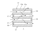
- the acidic gas adsorption unit 1 includes a plurality of adsorption units 17.
- the multiple adsorption parts 17 are stacked at intervals in the thickness direction. A flow path is formed between adjacent ones of the multiple adsorption parts 17. In the illustrated example, five adsorption parts 17 are arranged in parallel, but the number of adsorption parts 17 is not limited to this.
- the number of adsorption parts 17 is, for example, 5 or more, preferably 10 or more, and more preferably 20 or more.
- the interval between adjacent ones of the multiple adsorption parts 17 is, for example, 0.5 cm or more and 1.5 cm or less.
- Each of the multiple adsorption sections 17 includes multiple pellet-shaped adsorption materials 17a and a flexible fiber member 17b.
- the pellet-shaped adsorbent 17a functions as an acidic gas adsorbent, typically as a carbon dioxide adsorbent.
- materials for the pellet-shaped adsorbent 17a include materials modified with the above-mentioned acidic gas adsorbent, preferably cellulose modified with the above-mentioned acidic gas adsorbent, and more preferably nanofiberized cellulose modified with the above-mentioned acidic gas adsorbent.
- the average primary particle diameter of the pellet-shaped adsorbent 17a is, for example, 60 ⁇ m or more and 1200 ⁇ m or less.
- the filling ratio of the pellet-shaped adsorbent 17a in the adsorption section 17 may be any appropriate value.
- the flexible fiber member 17b is typically formed in a hollow shape (bag shape) capable of housing a plurality of pellet-shaped adsorbents 17a.
- the flexible fiber member 17b allows gas to pass through and restricts the passage of the pellet-shaped adsorbents.
- the flexible fiber member 17b may be a woven fabric or a nonwoven fabric.
- Examples of materials for the flexible fiber member 17b include organic fibers and natural fibers, and preferably include polyethylene terephthalate fibers, polyethylene fibers, and cellulose-based fibers.
- the thickness of the flexible fiber member 17b is, for example, 25 ⁇ m or more and 500 ⁇ m or less.
- the illustrated acid gas adsorption device 1 further includes a plurality of spacers 18.
- the spacers 18 are sandwiched between adjacent ones of the plurality of adsorption sections 17. This makes it possible to stably secure the spacing between adjacent adsorbent layers.
- the plurality of adsorption sections 17 and the plurality of spacers 18 are arranged so as to form an approximately zigzag shape when viewed from a direction perpendicular to the thickness direction of the adsorption section 17 (the depth direction of the paper in Figures 1A and 1B).
- the acidic gas adsorption section 1 includes a substrate 11 and an acidic gas adsorbent layer 16.
- the structure of the substrate 11 is not particularly limited, and examples thereof include a filter structure such as a honeycomb shape or a filter cloth; a pellet structure, etc.
- the acidic gas adsorbent layer 16 is not particularly limited as long as it is disposed on the surface of the substrate 11.
- the substrate 11 is a honeycomb-shaped substrate 11a.
- the honeycomb-shaped substrate 11a includes partition walls 13 that define a plurality of cells 14.
- the cells 14 extend in the length direction (axial direction) of the honeycomb substrate 11a from the first end face E1 (inlet end face) to the second end face E2 (outlet end face) of the honeycomb substrate 11a (see FIG. 4).
- the cells 14 have any suitable shape in a cross section perpendicular to the length direction of the honeycomb substrate 11a.
- Examples of the cross-sectional shape of the cells include a triangle, a square, a pentagon, a polygon having hexagons or more, a circle, and an ellipse.
- the cross-sectional shapes and sizes of the cells may all be the same, or may differ at least in part. Among such cross-sectional shapes of the cells, a hexagon or a square is preferable, and a square, a rectangle, or a hexagon is more preferable.
- the cell density i.e., the number of cells 14 per unit area
- the cell density can be appropriately set depending on the purpose.
- the cell density can be, for example, 4 cells/cm 2 to 320 cells/cm 2. If the cell density is in this range, the strength and effective GSA (geometric surface area) of the honeycomb substrate can be sufficiently ensured.
- the honeycomb substrate 11a has any suitable shape (overall shape). Examples of the shape of the honeycomb substrate include a cylindrical shape with a circular bottom, an elliptical cylinder with an elliptical bottom, a rectangular column with a polygonal bottom, and a column with an irregular bottom.
- the honeycomb substrate 11a in the illustrated example has a rectangular column shape.
- the outer diameter and length of the honeycomb substrate can be appropriately set depending on the purpose.
- the honeycomb substrate may have a hollow region in the center in a cross section perpendicular to the length direction.
- the honeycomb-shaped substrate 11a typically includes an outer wall 12 and a partition wall 13 located inside the outer wall 12.
- the outer wall 12 and the partition wall 13 are integrally formed.
- the outer wall 12 and the partition wall 13 may be separate bodies.
- the outer wall 12 has a rectangular cylindrical shape.
- the thickness of the outer wall 12 can be set arbitrarily and appropriately.
- the thickness of the outer wall 12 is, for example, 0.1 mm to 10 mm.
- the partitions 13 define a plurality of cells 14. More specifically, the partitions 13 have a first partition 13a and a second partition 13b that are perpendicular to each other, and the first partition 13a and the second partition 13b define a plurality of cells 14.
- the cross-sectional shape of the cells 14 is approximately rectangular. Note that the configuration of the partitions is not limited to the partitions 13 described above.
- the partitions may have a first partition extending in the radial direction and a second partition extending in the circumferential direction, which together define a plurality of cells.
- the thickness of the partition wall 13 can be appropriately set depending on the application of the acid gas adsorption device.
- the thickness of the partition wall 13 is typically thinner than the thickness of the outer wall 12.
- the thickness of the partition wall 13 is, for example, 0.03 mm to 0.6 mm.
- the thickness of the partition wall is measured, for example, by cross-sectional observation using a SEM (scanning electron microscope). If the thickness of the partition wall is within this range, the mechanical strength of the honeycomb substrate can be sufficient, and the opening area (total area of the cells in the cross section) can be sufficient.
- the porosity of the partition walls 13 can be appropriately set depending on the purpose.
- the porosity of the partition walls 13 is, for example, 15% or more, and preferably 20% or more.
- the porosity of the partition walls 13 is, for example, 70% or less, and preferably 45% or less.
- the porosity can be measured by, for example, mercury intrusion porosimetry.
- the bulk density of the partition walls 13 can be appropriately set depending on the purpose.
- the bulk density of the partition walls 13 is, for example, 0.10 g/cm 3 or more, preferably 0.20 g/cm 3 or more.
- the bulk density of the partition walls 13 is, for example, 0.60 g/cm 3 or less, preferably 0.50 g/cm 3 or less.
- the bulk density can be measured, for example, by mercury intrusion porosimetry.
- Ceramics are typical examples of materials that make up the partition wall 13.
- Examples of ceramics include silicon carbide, silicon-silicon carbide composite materials, cordierite, mullite, alumina, silicon nitride, spinel, silicon carbide-cordierite composite materials, lithium aluminum silicate, and aluminum titanate.
- the materials that make up the partition wall can be used alone or in combination.
- cordierite, alumina, mullite, silicon carbide, silicon-silicon carbide composite materials, and silicon nitride are preferred, and silicon carbide and silicon-silicon carbide composite materials are more preferred.
- Such a honeycomb-shaped substrate 11a is typically produced by the following method. First, a binder and water or an organic solvent are added as necessary to a material powder containing the above-mentioned ceramic powder, and the resulting mixture is kneaded to form a clay. The clay is then molded into a desired shape (typically by extrusion molding), and then dried and fired as necessary to produce the honeycomb-shaped substrate 11a. If fired, it is fired at, for example, 1200°C to 1500°C. The firing time is, for example, 1 hour or more and 20 hours or less.
- the acidic gas adsorbent layer 16 is formed on the surface of the partition wall 13 in the cell 14.
- the cell flow path 15 is formed in a portion (typically the center portion) in the cross section of the cell 14 where the acidic gas adsorbent layer 16 is not formed.
- the acidic gas adsorbent layer 16 may be formed on the entire inner surface of the partition wall 13 (i.e., so as to surround the cell flow path 15) as in the illustrated example, or may be formed on a part of the surface of the partition wall.
- the adsorption efficiency of the acidic gas typically CO 2
- the acidic gas typically CO 2
- the cell flow paths 15 extend from a first end face E1 (inlet end face) to a second end face E2 (outlet end face) like the cells 14.
- the cross-sectional shape of the cell flow paths 15 may be the same as that of the cells 14 described above, preferably a hexagon or a quadrangle, more preferably a square, a rectangle, or a hexagon.
- the cross-sectional shapes and sizes of the cell flow paths 15 may all be the same, or at least some may be different.
- the gas to be treated containing acidic gas is supplied to the cell 14 (more specifically, the cell flow path 15) in the adsorption step described below, and a heating medium flows through the cell 14 in the desorption step described below.
- the acid gas adsorbent layer 16 contains an acid gas adsorbent corresponding to the acid gas to be adsorbed.
- the acid gas is CO2
- the acid gas adsorbent layer 16 contains the above-mentioned carbon dioxide adsorbent.
- the acidic gas adsorbent layer may be composed only of an acidic gas adsorbent.
- the acidic gas adsorbent is directly supported on the partition wall 13 and faces the flow path.
- the content of the acidic gas adsorbent in the acidic gas adsorbent layer is typically 95.0% by mass or more and 100% by mass or less.
- excellent acidic gas adsorption efficiency can be stably ensured.
- the acidic gas adsorbent layer 16 further includes a porous carrier in addition to the acidic gas adsorbent described above.
- the acidic gas adsorbent is typically supported on the porous carrier and faces the flow path.
- the acidic gas adsorbent layer includes a porous carrier, it is possible to suppress the acidic gas adsorbent from falling off from the acidic gas adsorbent layer during the adsorption process and/or desorption process.
- the porous carrier can form mesopores in the acidic gas adsorbent layer.
- the porous carrier include metal-organic frameworks (MOFs) such as MOF-74, MOF-200, and MOF-210; activated carbon; nitrogen-doped carbon; mesoporous silica; mesoporous alumina; zeolites; carbon nanotubes; and fluoride resins such as polyvinylidene fluoride (PVDF).
- MOFs metal-organic frameworks
- activated carbon PVDF
- zeolites mesoporous silica
- mesoporous alumina are preferred.
- the porous carriers can be used alone or in combination.
- the porous carrier is preferably made of a material different from that of the acidic gas adsorbent.
- the BET specific surface area of the porous carrier is, for example, 50 m 2 /g or more, preferably 500 m 2 /g or more. If the surface area of the porous carrier is equal to or more than the lower limit, the acidic gas adsorbent can be stably supported, and the adsorption efficiency of the acidic gas can be improved.
- the upper limit of the BET specific surface area of the porous carrier is typically 2000 m 2 /g.
- the total content of the acidic gas adsorbent and the porous carrier in the acidic gas adsorbent layer is, for example, 30% by mass or more, preferably 50% by mass or more, whereas the total content of the acidic gas adsorbent and the porous carrier is, for example, 100% by mass or less, preferably 99% by mass or less.
- the content of the acidic gas adsorbent in the acidic gas adsorbent layer is, for example, 30% by mass or more, preferably 50% by mass or more.
- the content of the acidic gas adsorbent in the acidic gas adsorbent layer is, for example, 99% by mass or less.
- the content of the porous carrier is, for example, 0.01 parts by mass or more, preferably 0.3 parts by mass or more, per 1 part by mass of the acidic gas adsorbent.
- the content of the porous carrier is, for example, 0.7 parts by mass or less, preferably 0.5 parts by mass or less.
- Such an acidic gas adsorbent layer is typically produced by the following method.
- the above-mentioned acidic gas adsorbent is dissolved in a solvent to prepare a solution of the acidic gas adsorbent.
- the above-mentioned porous carrier is added to the solvent.
- the solution of the acidic gas adsorbent is applied onto a substrate (specifically, a partition wall), and the coating is dried and sintered as necessary to form an acidic gas adsorbent layer.
- the method for recovering acidic gas typically includes an adsorption step and a desorption step in this order.
- the gas to be treated is supplied to the acidic gas adsorption section 1 located in the flow path 21 of the storage section 2 to allow the acidic gas to be adsorbed by the acidic gas adsorbent.
- the first valve 51 and the second valve 52 are opened, and the gas to be treated containing the acidic gas is supplied to the flow path 21 of the storage section 2 via the first inlet 22.
- the gas to be treated containing the acidic gas passes through the acidic gas adsorption section 1.
- the acidic gas adsorbent contained in the acidic gas adsorption section 1 adsorbs the acidic gas (typically CO 2 ) and separates the acidic gas from the gas to be treated.
- the temperature (adsorption temperature) of the acidic gas adsorption section in the adsorption step is, for example, 0° C. or higher, preferably 10° C. or higher. Meanwhile, the adsorption temperature is, for example, 50° C. or lower, preferably 40° C. or lower. In one embodiment, the adsorption temperature is the same as the outside air temperature.
- the duration of the adsorption step (adsorption time) is, for example, 15 minutes or longer, preferably 30 minutes or longer. Meanwhile, the adsorption time is, for example, 3 hours or shorter, preferably 2 hours or shorter. When the adsorption temperature and/or the adsorption time are within the above ranges, the acidic gas adsorbent can efficiently adsorb acidic gases.
- the upper limit of the acid gas adsorption rate is typically 90%.
- the first valve 51 is closed and the second valve 52 is kept open, and the pressurizing device 62 is driven to start supplying the heating medium to the flow path 21. This replaces the gas to be treated in the flow path 21 with the heating medium.
- the desorption step is carried out.
- a heating medium having a pressure exceeding atmospheric pressure is supplied to the flow path 21 to heat the acidic gas adsorption section 1 to a predetermined desorption temperature, and the acidic gas is desorbed from the acidic gas adsorbent.
- the first valve 51 and the second valve 52 are closed, and then the pressurizing device 62 and the heating device 63 are driven.
- the pressurizing device 62 pressure-transmits the heating medium to the heating device 63 via a connecting line 64. In this way, the pressurized heating medium is supplied to the heating device 63.
- the heating device 63 heats the supplied heating medium.
- the heating temperature can be arbitrarily and appropriately adjusted depending on the heating medium.
- the heating temperature is a temperature that can adjust the acidic gas adsorption section to a desorption temperature range described below, and is, for example, equal to or higher than the desorption temperature. More specifically, the heating temperature is 70° C. to 160° C., and preferably 80° C. to 160° C. This allows the acidic gas to be efficiently desorbed from the acidic gas adsorbent. Thereafter, the pressurized and heated heating medium passes through the supply line 61 and is supplied to the storage space S, whereby the temperature of the acidic gas adsorption section 1 is raised to a predetermined desorption temperature and the storage space S is pressurized.
- the flow velocity of the heating medium supplied to the storage space S is, for example, 0.1 m/s to 8 m/s.
- the heating medium is typically supplied to the storage space S through the second inlet at such a flow velocity. Then, in the desorption step, the temperature difference specific heat coefficient (described later) of the heating medium can be suitably adjusted.
- the desorption temperature is, for example, 70° C. or higher, preferably 80° C. or higher. This allows the acid gas to be efficiently desorbed from the acid gas adsorbent. Meanwhile, the desorption temperature is, for example, 160° C. or lower, preferably 110° C. or lower. This allows the deterioration of the acid gas adsorbent to be stably suppressed.
- the desorption temperature can be confirmed by measuring the temperature immediately adjacent to the outlet (downstream end) of the acid gas adsorption section. When the acidic gas adsorption section reaches the desorption temperature, the pressure in the storage space S is, for example, 0.12 MPaA or more, preferably 0.16 MPaA or more.
- the pressure in the storage space S is, for example, 1.0 MPaA or less, preferably 0.7 MPaA or less. This can suppress the plate thickness of each member of the storage section, and suppress the decrease in heating efficiency due to the increase in the heat capacity of the storage section.
- the implementation time of the desorption step (specifically, the time during which the acidic gas adsorption section is maintained at the above-mentioned desorption temperature and the accommodation space is maintained at the above-mentioned pressure) is, for example, 1 minute or more, preferably 5 minutes or more, whereas the implementation time of the desorption step is, for example, 1 hour or less, preferably 30 minutes or less.
- the acidic gas adsorbed by the acidic gas adsorbent in the adsorption process is desorbed from the acidic gas adsorbent. Therefore, the recovered gas containing the heating medium that has passed through the acidic gas adsorption section 1 and the acidic gas desorbed from the acidic gas adsorbent flows out of the storage section 2 through the second outlet 25.
- the temperature difference specific heat coefficient ⁇ Cp/ ⁇ T of the heating medium satisfies the following formula (1).
- the acidic gas recovery system 100 is configured so that the ⁇ Cp/ ⁇ T of the heating medium satisfies the following formula (1). More specifically, when the acidic gas adsorption unit 1 is maintained at the above desorption temperature and the storage space S is maintained at the above pressure, the temperature difference specific heat coefficient ⁇ Cp/ ⁇ T of the heating medium satisfies the following formula (1).
- the acidic gas adsorption section can be efficiently heated by setting ⁇ Cp/ ⁇ T (also referred to as the temperature difference specific heat coefficient) in the above range.
- ⁇ Cp/ ⁇ T is preferably 0.038 J/(mol ⁇ K 2 ) or less.
- the lower limit of ⁇ Cp/ ⁇ T is typically ⁇ 1.1 J/(mol ⁇ K 2 ). If ⁇ Cp/ ⁇ T is in this range, the energy required to heat the acidic gas adsorption section can be further reduced.
- ⁇ Cp constant pressure molar specific heat a ⁇ constant pressure molar specific heat b
- the constant pressure molar specific heat a at the inlet of the heating medium flow path 21 can be calculated by measuring the temperature and pressure immediately adjacent to the inlet (upstream end) of the acidic gas adsorption section 1.
- the heating medium is a mixed gas
- the composition of the mixed gas immediately adjacent to the inlet of the acidic gas adsorption section 1 is measured, and the constant pressure molar specific heat a is calculated by multiplying the composition ratio of each gas by the sum of the constant pressure molar specific heat of the corresponding gas.
- the constant pressure molar specific heat b of the recovered gas discharged from the flow path 21 can be calculated by measuring the temperature and pressure immediately adjacent to the outlet (downstream end) of the acidic gas adsorption section 1.
- the composition of the mixed gas immediately adjacent to the outlet of the acidic gas adsorption section 1 is measured, and the constant pressure molar specific heat b is calculated by multiplying the composition ratio of each gas by the sum of the constant pressure molar specific heat of the corresponding gas.
- the range of temperature a of the heating medium supplied to the flow path 21 (the heating medium when passing through the second inlet) is the same as the range of the heating temperature in the heating device described above.
- the recovered gas that has passed through the second outlet 25 is supplied to the storage tank 42 via the recovery line 41 and stored in the storage tank 42 .
- the internal pressure of the storage tank 42 is, for example, 0.12 MPaA to 1.0 MPaA, and preferably 0.16 MPaA to 0.7 MPaA. Therefore, the recovered gas stored in the storage tank 42 can be smoothly supplied to another device when it is used for various applications (for example, as a raw material for synthetic fuel). Also, as described above, at least a part of the recovered gas can be returned as a heating medium to the heating medium supply unit 6 by the return unit 3. When the internal pressure of the storage tank is within the above range, at least a part of the recovered gas can be used as a heating medium without additional pressure adjustment, and the energy required for pressurization can be further reduced.
- the method for recovering acidic gas may include a cooling step in addition to the adsorption step and the desorption step.
- the cooling step is carried out after the desorption step and before the adsorption step, and cools the acidic gas adsorption section to the above-mentioned adsorption temperature.
- the adsorption step, desorption step, and cooling step are preferably carried out continuously by repeating them in order.
- Example 1 An acidic gas recovery system as shown in Fig. 1A was prepared.
- the acidic gas recovery system was provided with the above-mentioned acidic gas adsorption section, the above-mentioned storage section, the above-mentioned heating medium supply section, and the above-mentioned recovery section.
- the acidic gas adsorption section was provided with the above-mentioned honeycomb substrate and the above-mentioned acidic gas adsorbent layer.
- the above-mentioned adsorption step and the above-mentioned desorption step were carried out in sequence by the acid gas recovery system.
- the pressure of the storage space accommodating the acidic gas adsorption section was maintained at 0.16 MPa in the storage section.
- the heating medium supply section supplied carbon dioxide as a heating medium to the flow path of the storage section through the second inlet.
- the recovered gas containing the carbon dioxide that had passed through the acidic gas adsorption section and the carbon dioxide desorbed from the acidic gas adsorbent was discharged from the storage section through the second outlet.
- Table 1 shows the pressure and temperature (supply temperature a) of the heating medium passing through the second inlet, the temperature (discharge temperature b) of the recovery gas passing through the second outlet, the temperature difference ⁇ T therebetween, and ⁇ Cp/ ⁇ T.
- the temperature difference in the acid gas adsorption section was maintained within 10° C. during the desorption step.
- Examples 2 and 3> The desorption step was carried out in the same manner as in Example 1, except that the supply temperature a was changed to a value shown in Table 1. In the desorption step, the temperature difference in the acidic gas adsorption section was maintained within ⁇ T shown in Table 1.
- Examples 4 to 6> Except for changing the pressure of the heating medium passing through the second inlet to 0.210 MPa, the desorption step was carried out in the same manner as in Examples 1 to 3. In the desorption step, the temperature difference in the acidic gas adsorption section was maintained within ⁇ T shown in Table 1.
- Example 1 The desorption step was carried out in the same manner as in Example 1, except that the heating medium supplying unit supplied carbon dioxide at atmospheric pressure (0.101 MPaA) as the heating medium to the flow path of the storage unit. In the desorption step, the temperature difference in the acidic gas adsorption unit was maintained within 1°C.
- Example 3 the pressure of the heating medium is lower than those of Examples 4 to 6, and the supply temperature of the heating medium is lower than those of Examples 1, 2, 4, and 5, so that the energy required to heat the acidic gas adsorption section is the smallest.
- ⁇ Cp/ ⁇ T is 0.039 (J/(mol ⁇ K 2 )) or less, so that the acidic gas adsorption section can be sufficiently heated with energy saving in the desorption process.
- the acid gas recovery system and acid gas recovery method according to the embodiment of the present invention are used to separate and recover acid gases, and are particularly suitable for use in the carbon dioxide capture, utilization, and storage (CCUS) cycle.
- CCUS carbon dioxide capture, utilization, and storage
Landscapes
- Chemical & Material Sciences (AREA)
- Chemical Kinetics & Catalysis (AREA)
- Engineering & Computer Science (AREA)
- Analytical Chemistry (AREA)
- General Chemical & Material Sciences (AREA)
- Oil, Petroleum & Natural Gas (AREA)
- Organic Chemistry (AREA)
- Inorganic Chemistry (AREA)
- Separation Of Gases By Adsorption (AREA)
Priority Applications (5)
| Application Number | Priority Date | Filing Date | Title |
|---|---|---|---|
| JP2025513892A JPWO2024214571A1 (https=) | 2023-04-12 | 2024-03-29 | |
| AU2024255626A AU2024255626A1 (en) | 2023-04-12 | 2024-03-29 | Acid gas recovery system and acid gas recovery method |
| CN202480013351.8A CN120897789A (zh) | 2023-04-12 | 2024-03-29 | 酸性气体回收系统及酸性气体的回收方法 |
| EP24788599.9A EP4696402A1 (en) | 2023-04-12 | 2024-03-29 | Acid gas recovery system and acid gas recovery method |
| US19/322,804 US20260001027A1 (en) | 2023-04-12 | 2025-09-09 | Acid gas capture system and acid gas capture method |
Applications Claiming Priority (2)
| Application Number | Priority Date | Filing Date | Title |
|---|---|---|---|
| JP2023-064972 | 2023-04-12 | ||
| JP2023064972 | 2023-04-12 |
Related Child Applications (1)
| Application Number | Title | Priority Date | Filing Date |
|---|---|---|---|
| US19/322,804 Continuation US20260001027A1 (en) | 2023-04-12 | 2025-09-09 | Acid gas capture system and acid gas capture method |
Publications (1)
| Publication Number | Publication Date |
|---|---|
| WO2024214571A1 true WO2024214571A1 (ja) | 2024-10-17 |
Family
ID=93059258
Family Applications (1)
| Application Number | Title | Priority Date | Filing Date |
|---|---|---|---|
| PCT/JP2024/013064 Ceased WO2024214571A1 (ja) | 2023-04-12 | 2024-03-29 | 酸性ガス回収システムおよび酸性ガスの回収方法 |
Country Status (6)
| Country | Link |
|---|---|
| US (1) | US20260001027A1 (https=) |
| EP (1) | EP4696402A1 (https=) |
| JP (1) | JPWO2024214571A1 (https=) |
| CN (1) | CN120897789A (https=) |
| AU (1) | AU2024255626A1 (https=) |
| WO (1) | WO2024214571A1 (https=) |
Citations (5)
| Publication number | Priority date | Publication date | Assignee | Title |
|---|---|---|---|---|
| JP2013147386A (ja) * | 2012-01-20 | 2013-08-01 | Hitachi Ltd | Co2分離回収装置 |
| JP2014004533A (ja) * | 2012-06-25 | 2014-01-16 | Toshiba Corp | 酸性ガス吸収剤、酸性ガス除去方法および酸性ガス除去装置 |
| WO2014170184A1 (en) | 2013-04-18 | 2014-10-23 | Climeworks Ag | Low-pressure drop structure of particle adsorbent bed for adsorption gas separation process |
| JP2019069417A (ja) * | 2017-10-10 | 2019-05-09 | 株式会社日立製作所 | 排ガスからの二酸化炭素回収方法及び設備 |
| JP2023147421A (ja) * | 2022-03-30 | 2023-10-13 | 旭化成株式会社 | 気体組成物の製造方法、少なくとも二酸化炭素に由来する物質の製造方法及び固体吸着剤の再生方法 |
-
2024
- 2024-03-29 WO PCT/JP2024/013064 patent/WO2024214571A1/ja not_active Ceased
- 2024-03-29 AU AU2024255626A patent/AU2024255626A1/en active Pending
- 2024-03-29 EP EP24788599.9A patent/EP4696402A1/en active Pending
- 2024-03-29 CN CN202480013351.8A patent/CN120897789A/zh active Pending
- 2024-03-29 JP JP2025513892A patent/JPWO2024214571A1/ja active Pending
-
2025
- 2025-09-09 US US19/322,804 patent/US20260001027A1/en active Pending
Patent Citations (5)
| Publication number | Priority date | Publication date | Assignee | Title |
|---|---|---|---|---|
| JP2013147386A (ja) * | 2012-01-20 | 2013-08-01 | Hitachi Ltd | Co2分離回収装置 |
| JP2014004533A (ja) * | 2012-06-25 | 2014-01-16 | Toshiba Corp | 酸性ガス吸収剤、酸性ガス除去方法および酸性ガス除去装置 |
| WO2014170184A1 (en) | 2013-04-18 | 2014-10-23 | Climeworks Ag | Low-pressure drop structure of particle adsorbent bed for adsorption gas separation process |
| JP2019069417A (ja) * | 2017-10-10 | 2019-05-09 | 株式会社日立製作所 | 排ガスからの二酸化炭素回収方法及び設備 |
| JP2023147421A (ja) * | 2022-03-30 | 2023-10-13 | 旭化成株式会社 | 気体組成物の製造方法、少なくとも二酸化炭素に由来する物質の製造方法及び固体吸着剤の再生方法 |
Non-Patent Citations (1)
| Title |
|---|
| See also references of EP4696402A1 |
Also Published As
| Publication number | Publication date |
|---|---|
| TW202448572A (zh) | 2024-12-16 |
| AU2024255626A1 (en) | 2025-10-23 |
| JPWO2024214571A1 (https=) | 2024-10-17 |
| EP4696402A1 (en) | 2026-02-18 |
| CN120897789A (zh) | 2025-11-04 |
| US20260001027A1 (en) | 2026-01-01 |
Similar Documents
| Publication | Publication Date | Title |
|---|---|---|
| AU2008254961B2 (en) | Temperature swing adsorption of CO2 from flue gas utilizing heat from compression | |
| US20250242292A1 (en) | Acid gas capture system | |
| US20250229213A1 (en) | Acid gas adsorption device | |
| US20250242304A1 (en) | Method of capturing an acid gas | |
| US20250242289A1 (en) | Method of capturing an acid gas | |
| WO2024214571A1 (ja) | 酸性ガス回収システムおよび酸性ガスの回収方法 | |
| TWI916798B (zh) | 酸性氣體回收系統及酸性氣體之回收方法 | |
| WO2024214570A1 (ja) | 酸性ガス回収システムおよび酸性ガスの回収方法 | |
| TWI922928B (zh) | 酸性氣體回收系統及酸性氣體之回收方法 | |
| WO2024048578A1 (ja) | 酸性ガス吸着装置 | |
| AU2023334312B2 (en) | Acidic-gas adsorption device | |
| WO2025088956A1 (ja) | 酸性ガス吸着装置 | |
| US20260091341A1 (en) | Acid gas adsorption device | |
| TW202542453A (zh) | 燃燒尾氣之二氧化碳處理系統及其方法 |
Legal Events
| Date | Code | Title | Description |
|---|---|---|---|
| 121 | Ep: the epo has been informed by wipo that ep was designated in this application |
Ref document number: 24788599 Country of ref document: EP Kind code of ref document: A1 |
|
| WWE | Wipo information: entry into national phase |
Ref document number: 202480013351.8 Country of ref document: CN |
|
| ENP | Entry into the national phase |
Ref document number: 2025513892 Country of ref document: JP Kind code of ref document: A |
|
| WWE | Wipo information: entry into national phase |
Ref document number: 2025513892 Country of ref document: JP |
|
| WWE | Wipo information: entry into national phase |
Ref document number: AU2024255626 Country of ref document: AU |
|
| ENP | Entry into the national phase |
Ref document number: 2024255626 Country of ref document: AU Date of ref document: 20240329 Kind code of ref document: A |
|
| WWP | Wipo information: published in national office |
Ref document number: 202480013351.8 Country of ref document: CN |
|
| WWE | Wipo information: entry into national phase |
Ref document number: 2024788599 Country of ref document: EP |
|
| NENP | Non-entry into the national phase |
Ref country code: DE |
|
| ENP | Entry into the national phase |
Ref document number: 2024788599 Country of ref document: EP Effective date: 20251112 |
|
| ENP | Entry into the national phase |
Ref document number: 2024788599 Country of ref document: EP Effective date: 20251112 |
|
| ENP | Entry into the national phase |
Ref document number: 2024788599 Country of ref document: EP Effective date: 20251112 |
|
| ENP | Entry into the national phase |
Ref document number: 2024788599 Country of ref document: EP Effective date: 20251112 |
|
| ENP | Entry into the national phase |
Ref document number: 2024788599 Country of ref document: EP Effective date: 20251112 |
|
| ENP | Entry into the national phase |
Ref document number: 2024788599 Country of ref document: EP Effective date: 20251112 |
|
| ENP | Entry into the national phase |
Ref document number: 2024788599 Country of ref document: EP Effective date: 20251112 |
|
| ENP | Entry into the national phase |
Ref document number: 2024788599 Country of ref document: EP Effective date: 20251112 |
|
| ENP | Entry into the national phase |
Ref document number: 2024788599 Country of ref document: EP Effective date: 20251112 |
|
| WWP | Wipo information: published in national office |
Ref document number: 2024788599 Country of ref document: EP |