WO2024214381A1 - 画像処理装置、画像処理方法及びプログラム - Google Patents
画像処理装置、画像処理方法及びプログラム Download PDFInfo
- Publication number
- WO2024214381A1 WO2024214381A1 PCT/JP2024/004990 JP2024004990W WO2024214381A1 WO 2024214381 A1 WO2024214381 A1 WO 2024214381A1 JP 2024004990 W JP2024004990 W JP 2024004990W WO 2024214381 A1 WO2024214381 A1 WO 2024214381A1
- Authority
- WO
- WIPO (PCT)
- Prior art keywords
- image
- target frame
- pixel
- noise removal
- value
- Prior art date
- Legal status (The legal status is an assumption and is not a legal conclusion. Google has not performed a legal analysis and makes no representation as to the accuracy of the status listed.)
- Ceased
Links
Images










Classifications
-
- H—ELECTRICITY
- H04—ELECTRIC COMMUNICATION TECHNIQUE
- H04N—PICTORIAL COMMUNICATION, e.g. TELEVISION
- H04N23/00—Cameras or camera modules comprising electronic image sensors; Control thereof
- H04N23/80—Camera processing pipelines; Components thereof
- H04N23/81—Camera processing pipelines; Components thereof for suppressing or minimising disturbance in the image signal generation
-
- G—PHYSICS
- G06—COMPUTING OR CALCULATING; COUNTING
- G06T—IMAGE DATA PROCESSING OR GENERATION, IN GENERAL
- G06T5/00—Image enhancement or restoration
- G06T5/50—Image enhancement or restoration using two or more images, e.g. averaging or subtraction
-
- G—PHYSICS
- G06—COMPUTING OR CALCULATING; COUNTING
- G06T—IMAGE DATA PROCESSING OR GENERATION, IN GENERAL
- G06T5/00—Image enhancement or restoration
- G06T5/70—Denoising; Smoothing
-
- G—PHYSICS
- G06—COMPUTING OR CALCULATING; COUNTING
- G06T—IMAGE DATA PROCESSING OR GENERATION, IN GENERAL
- G06T2207/00—Indexing scheme for image analysis or image enhancement
- G06T2207/10—Image acquisition modality
- G06T2207/10016—Video; Image sequence
-
- G—PHYSICS
- G06—COMPUTING OR CALCULATING; COUNTING
- G06T—IMAGE DATA PROCESSING OR GENERATION, IN GENERAL
- G06T2207/00—Indexing scheme for image analysis or image enhancement
- G06T2207/10—Image acquisition modality
- G06T2207/10024—Color image
-
- G—PHYSICS
- G06—COMPUTING OR CALCULATING; COUNTING
- G06T—IMAGE DATA PROCESSING OR GENERATION, IN GENERAL
- G06T2207/00—Indexing scheme for image analysis or image enhancement
- G06T2207/20—Special algorithmic details
- G06T2207/20172—Image enhancement details
- G06T2207/20182—Noise reduction or smoothing in the temporal domain; Spatio-temporal filtering
-
- G—PHYSICS
- G06—COMPUTING OR CALCULATING; COUNTING
- G06T—IMAGE DATA PROCESSING OR GENERATION, IN GENERAL
- G06T2207/00—Indexing scheme for image analysis or image enhancement
- G06T2207/20—Special algorithmic details
- G06T2207/20212—Image combination
- G06T2207/20216—Image averaging
Definitions
- the present invention relates to an image processing device, an image processing method, and a program.
- time-series images obtained by continuous shooting have been widely used.
- time-series images moving images obtained by continuous shooting have been widely used.
- a video processing device In order to reduce noise, for example, a video processing device has been proposed that estimates the motion between a frame of interest among the multiple frames that make up a moving image and the frames before and after it (see Patent Document 1). This device detects pixel-by-pixel motion vectors from temporally consecutive frames, and determines the boundary between foreground objects and the background to reduce noise.
- the present invention was made in consideration of the problems with the conventional technology described above, and aims to improve image quality while avoiding the side effects of removing temporal noise.
- the invention described in claim 1 is an image processing device that processes each of a plurality of frames constituting a time-series image as a target frame, and includes a first processing unit that performs a temporal noise removal process for each pixel based on the target frame and a frame that precedes the target frame, and generates a first processed image for the target frame, a second processing unit that performs a spatial noise removal process on the target frame, and generates a second processed image for the target frame, and an output value determination unit that outputs the pixel value of the first processed image for each pixel of the target frame if the absolute value of the difference between the pixel value of the first processed image and the pixel value of the second processed image is equal to or less than a predetermined value, and outputs the pixel value of the target frame if the absolute value of the difference is greater than the predetermined value.
- the invention described in claim 2 is the image processing device described in claim 1, in which the first processing unit uses the first processed image generated for the frame immediately preceding the target frame for the temporal noise removal process in the target frame.
- the invention described in claim 3 is the image processing device described in claim 1, in which the first processing unit takes the average of the target frame and a predetermined number of frames prior to the target frame.
- the invention described in claim 4 is the image processing device described in claim 1, in which the second processing unit calculates the average of each pixel of the target frame and its surrounding pixels.
- the invention described in claim 5 is the image processing device described in claim 4, in which the second processing unit includes a line memory that stores pixel values for a predetermined number of lines of the target frame, and the range of the surrounding pixels in a direction parallel to the lines is wider than the range of the surrounding pixels in a direction perpendicular to the lines.
- the invention described in claim 6 is the image processing device described in claim 1, in which the time-series image is a Bayer image, and the second processing unit calculates, for each pixel of the target frame, the average of that pixel and surrounding pixels of the same color as that pixel.
- the invention described in claim 7 is an image processing device described in any one of claims 1 to 6, in which the pixel values of the time-series image are density values that represent the density of the image.
- the invention described in claim 8 is an image processing device described in any one of claims 1 to 6, in which the pixel values of the time-series images are numerical values representing distances.
- the invention described in claim 9 is an image processing method for processing each of a plurality of frames constituting a time-series image as a target frame, and includes a first processing step for performing a temporal noise removal process for each pixel based on the target frame and a frame that precedes the target frame, and generating a first processed image for the target frame; a second processing step for performing a spatial noise removal process for the target frame, and generating a second processed image for the target frame; and an output value determination step for outputting, for each pixel of the target frame, the pixel value of the first processed image if the absolute value of the difference between the pixel value of the first processed image and the pixel value of the second processed image is equal to or less than a predetermined value, and outputting the pixel value of the target frame if the absolute value of the difference is greater than the predetermined value.
- the invention described in claim 10 is a program for causing a computer of an image processing device, which processes each of a plurality of frames constituting a time-series image as a target frame, to function as a first processing unit that performs temporal noise removal processing for each pixel based on the target frame and a frame that precedes the target frame, and generates a first processed image for the target frame, a second processing unit that performs spatial noise removal processing on the target frame, and generates a second processed image for the target frame, and an output value determination unit that outputs, for each pixel of the target frame, the pixel value of the first processed image if the absolute value of the difference between the pixel value of the first processed image and the pixel value of the second processed image is equal to or less than a predetermined value, and outputs the pixel value of the target frame if the absolute value of the difference is greater than the predetermined value.
- the present invention makes it possible to improve image quality while avoiding side effects caused by removing temporal noise.
- FIG. 1 is a block diagram showing a configuration of an image processing system according to an embodiment of the present invention.
- 4 is a flowchart showing image processing executed in the image processing device.
- 11 is a graph showing a function param(diff) used in the time noise removal process.
- FIG. 13 is a diagram showing the result of performing a time noise removal process on stationary time-series image data.
- FIG. 11 is a graph showing changes over time in an input pixel value of a target pixel and an output pixel value after a time noise removal process; 11 is a diagram showing the standard deviation of an input pixel value of a target pixel and an output pixel value after a time noise removal process.
- FIGS. 11A and 11B are diagrams showing the results of performing a time noise removal process on time-series image data containing motion.
- 13 is an example of a spatial filter used in the spatial noise removal process.
- FIG. 13 is a diagram showing the results of spatial noise removal processing performed on motionless time-series image data.
- FIG. 11 is a graph showing changes over time in an input pixel value of a target pixel and an output pixel value after spatial noise removal processing; 11 is a diagram showing the standard deviation of the input pixel value of a target pixel and the output pixel value after spatial noise removal processing.
- FIG. FIG. 13 is a diagram showing the results of spatial noise removal processing performed on time-series image data containing motion. 13 is a flowchart showing an output value determination process.
- FIG. 13A and 13B are diagrams showing an image after time noise removal processing is performed on motionless time-series image data and an output image.
- FIG. 1 is a graph showing changes over time in input pixel value and output pixel value of a target pixel.
- FIG. 13 is a diagram showing the standard deviation of the input pixel value and the output pixel value of a target pixel.
- 13A and 13B are diagrams showing an image after a time noise removal process is performed on time-series image data containing motion, and an output image.
- 13A and 13B are diagrams illustrating target pixels in the temporal noise removal process of Modification 1.
- 11 is a graph showing changes over time in the input pixel value of a target pixel, the average value for the past 30 frames, and the average value for the past 40 frames.
- FIG. 13 is a diagram showing an input pixel value of a target pixel, an average value of the past 30 frames, and a standard deviation of the average value of the past 40 frames.
- FIG. 13 is a graph showing a function param(diff) used in the time noise removal process of the second modified example.
- 13 is an example of a spatial filter used in the spatial noise removal process of Modification 3.
- 13 is an example of a Bayer arrangement in Modification 4.
- 1 is an example of a spatial filter for a Bayer image.
- FIG. 13 is a diagram showing input and output images in the form of Bayer images in the case where stationary time-series image data is used;
- FIG. 13 is a diagram showing input and output images in the form of Bayer images in the case where time-series image data containing motion is targeted.
- 13A and 13B are colorized diagrams of input and output images in the case of motionless time-series image data.
- 13A and 13B are diagrams showing colorized input and output images in the case
- FIG. 1 is a block diagram showing the configuration of an image processing system 100. As shown in FIG.
- the image processing system 100 includes a camera 10 and an image processing device 20. Note that the image processing device 20 may include the camera 10.
- the camera 10 captures images of a subject successively in time to generate time-series images.
- the time-series images are made up of a number of frames.
- the camera 10 includes a lens 11, a filter 12, an image sensor 13, and a signal processing unit 14.
- the lens 11 forms an image of a subject on the image sensor 13 .
- the filters 12 are primary color filters corresponding to R (red), G (green), and B (blue), respectively.
- the filters 12 pass light having specific wavelengths corresponding to each of RGB out of the light that has passed through the lens 11.
- the image sensor 13 is a two-dimensional image sensor that receives light that has passed through the filter 12 and outputs a signal according to the intensity of the received light.
- the signal processing unit 14 converts the analog signal output from the imaging element 13 into a digital signal, and performs known signal processing on the converted digital signal.
- the image processing device 20 processes each of a plurality of frames constituting a time-series image as a target frame.
- the pixel values of the time-series image are density values (luminance values) that represent the density of the image.
- the image processing device 20 is a personal computer, a mobile device, a smartphone, a tablet terminal, or the like.
- the image processing device 20 includes a control unit 21 , an operation unit 22 , a display unit 23 , a communication unit 24 , a storage unit 25 , and an image processing unit 26 .
- the control unit 21 includes a CPU (Central Processing Unit), a RAM (Random Access Memory), etc.
- the CPU reads out various programs stored in the storage unit 25, expands them in the RAM, executes various processes according to the expanded programs, and centrally controls the operation of each part of the image processing device 20.
- the operation unit 22 accepts operations by the user and outputs a control signal corresponding to the operation to the control unit 21.
- the operation unit 22 includes a keyboard, a pointing device, a touch panel, etc.
- the keyboard includes cursor keys, letter and number input keys, various function keys, etc.
- the pointing device is, for example, a mouse.
- the touch panel is layered on the surface of the display unit 23, and detects the position coordinates of the user's touch.
- the display unit 23 is an LCD (Liquid Crystal Display), an organic EL display, etc.
- the display unit 23 displays a screen, etc., according to the image signal output from the control unit 21.
- the communication unit 24 is a communication interface that communicates with the camera 10.
- the communication unit 24 receives image data of time-series images from the camera 10.
- the storage unit 25 is composed of a non-volatile memory, a hard disk, etc.
- the storage unit 25 stores various programs executed by the CPU of the control unit 21, parameters required for executing the programs, etc.
- the image processing unit 26 performs image processing on the image data of the time-series image acquired from the camera 10.
- the image processing unit 26 includes a temporal noise removal unit 27, a spatial noise removal unit 28, and an output value determination unit 29.
- the temporal noise removal unit 27, the spatial noise removal unit 28, and the output value determination unit 29 are realized by the CPU of the control unit 21 executing a program corresponding to each unit. Note that some or all of the functions of the temporal noise removal unit 27, the spatial noise removal unit 28, and the output value determination unit 29 may be realized by processing using a hardware circuit such as an FPGA (Field Programmable Gate Array).
- FPGA Field Programmable Gate Array
- the temporal noise removal unit 27 (first processing unit) performs temporal noise removal processing for each pixel based on a target frame and a frame that precedes the target frame, and generates a post-temporal noise removal processing image (first post-processing image) for the target frame.
- the temporal noise removal processing is processing for removing noise from an input image by smoothing pixel values in the time direction for a time-series image.
- the temporal noise removal unit 27 uses the image after the temporal noise removal process generated for the frame immediately preceding the target frame, in the temporal noise removal process for the target frame.
- the spatial noise removal unit 28 performs spatial noise removal processing on the target frame to generate a spatial noise removed image (second processed image) for the target frame.
- the spatial noise removal processing is processing for removing noise from the input image by smoothing pixel values within the same frame of the time-series image.
- the spatial noise removal process is a process of taking the average of each pixel of the target frame and its surrounding pixels. The range of surrounding pixels can be changed as appropriate depending on the spatial filter used in the spatial noise removal process.
- the spatial noise removal unit 28 may take the average by changing the weighting of each pixel (weighted average).
- the output value determination unit 29 calculates the absolute value of the difference between the pixel value of the image after temporal noise removal processing (first processed image) and the pixel value of the image after spatial noise removal processing (second processed image) for each pixel of the target frame. If the absolute value of this difference is equal to or less than a predetermined value, the output value determination unit 29 outputs the pixel value of the image after temporal noise removal processing. If the absolute value of this difference is greater than the predetermined value, the output value determination unit 29 outputs the pixel value of the target frame.
- [Operation of the image processing device] 2 is a flowchart showing image processing executed in the image processing device 20. This processing is performed for each of a plurality of frames constituting a time-series image as a target frame.
- the input pixel value and the output pixel value in the image processing are both 12 bits long (0 to 4095), and the frame rate is 30 fps.
- the temporal noise removal unit 27 performs a temporal noise removal process on a target frame (step A1).
- the temporal noise removal unit 27 performs the following process on each pixel in the image.
- the input pixel value of the current frame (target frame) is defined as In .
- the output pixel value after the temporal noise removal process of the current frame is denoted by T n
- the output pixel value after the temporal noise removal process of the previous frame is denoted by T n-1 .
- the temporal noise removal unit 27 holds the output pixel value T n-1 after the temporal noise removal process of the previous frame in a memory.
- the memory may be provided within the temporal noise removal unit 27, or may be the storage unit 25.
- the absolute value of the difference between the input pixel value I n of the current frame and the output pixel value T n-1 after the temporal noise removal process of the previous frame is shifted 4 bits to the right and defined as diff.
- diff can take a value from 0 to 255.
- bit shift is a process for changing the range (width) that diff can take. Even after the bit shift, diff still indicates the magnitude of the absolute value of the difference between the input pixel value I n of the current frame and the output pixel value T n-1 after the temporal noise removal process of the previous frame.
- the output pixel value T n after the temporal noise removal process of the current frame is calculated by the following equation (2).
- the temporal noise removal unit 27 performs weighted addition of the output pixel value T n-1 after the temporal noise removal process of the previous frame and the input pixel value I n of the current frame, and outputs the output pixel value T n after the temporal noise removal process of the current frame.
- param(diff) corresponds to the weighting for past frames in the temporal noise removal process. As shown in Fig. 3, when diff is equal to or less than a threshold th, param(diff) is param max . The closer param max is to 1, the stronger the weighting of past outputs. The closer param max is to 1, the same effect as averaging frames over a longer period of time can be obtained.
- the input pixel value In of the current frame is output as is to prevent the generation of unnecessary afterimages.
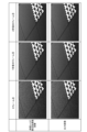
- Figure 4 shows the results of performing temporal noise removal processing on stationary time-series image data.
- Stationary time-series image data does not contain any moving objects as subjects.
- Figure 4 shows input images for frames 0, 30, and 60, and images after performing temporal noise removal processing on each input image. As shown in Figure 4, noise has been removed by temporal noise removal processing in frames 30 and 60.
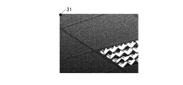
- the upper left pixel is set as a target pixel 31 as shown in FIG. 5A.
- 5B shows the change over time of the input pixel value I n and the output pixel value T n after the temporal noise removal process for the target pixel 31.
- the horizontal axis is the frame number
- the vertical axis is the pixel value.
- the frame number corresponds to the passage of time.
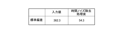
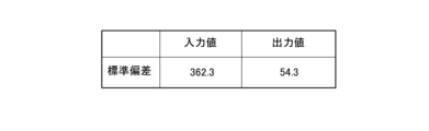
- Fig. 5C shows the standard deviation of the input pixel values I n in frames 50 to 149 shown in Fig. 5B, and the standard deviation of the output pixel values T n after the temporal noise removal process.
- the noise level (variation in pixel values) can be determined.
- the temporal noise removal process (see formulas (1), (2), Fig. 3) changes the standard deviation of the pixel values from "362.3” before the process to "54.3” after the process. In other words, it can be seen that the noise level has been improved by the temporal noise removal process.
- Fig. 6 shows the result of performing temporal noise removal processing on time-series image data with motion.
- the time-series image data with motion includes a moving object as a subject.
- Fig. 6 shows input images of the 0th, 30th, and 60th frames, and images after performing temporal noise removal processing on each input image. As shown in Fig. 6, afterimages appear in the 30th and 60th frames due to the temporal noise removal processing.
- the spatial noise removal unit 28 performs spatial noise removal process on the target frame (step A2).
- the spatial noise removal unit 28 creates an image from which noise has been removed by averaging the pixel values of the pixel of interest and the pixels surrounding the pixel of interest.
- FIG. 7 An example of a spatial filter is shown in Figure 7.
- W(i,j) be the weighting factor at each position in the filter.
- the input pixel value at a pixel position (x, y) in the current frame (target frame) is defined as I n (x, y).
- the output pixel value S n (x, y) after the spatial noise removal process at the pixel position (x, y) is calculated by the following equation (3):
- 49 (7 ⁇ 7) pixel values are averaged.
- the output pixel value S n (x, y) after spatial noise removal processing may be simply referred to as S n , omitting the pixel position (x, y).
- the input pixel value I n (x, y) may also be written simply as I n omitting the pixel position (x, y).
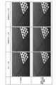
- Figure 8 shows the results of spatial noise removal processing on stationary time-series image data.
- Figure 8 shows input images for frames 0, 30, and 60, as well as the images after spatial noise removal processing was performed on each input image.
- the upper left pixel is set as a target pixel 31 as shown in FIG. 9A.
- 9B shows the change over time of the input pixel value I n and the output pixel value S n after spatial noise removal processing for the target pixel 31.
- the horizontal axis represents the frame number
- the vertical axis represents the pixel value.
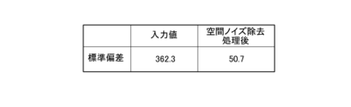
- Fig. 9C shows the standard deviation of the input pixel values I n in frames 50 to 149 shown in Fig. 9B, and the standard deviation of the output pixel values S n after spatial noise removal processing.
- the spatial noise removal processing (Equation (3), see Fig. 7) changes the standard deviation of the pixel values from "362.3" before processing to "50.7" after processing. It can be seen that the noise level (standard deviation) in the image after spatial noise removal processing has been improved to the same extent as the image after temporal noise removal processing (see Fig. 5C).
- the output value determination unit 29 compares the results of processing using the time filter with the results of processing using the spatial filter. For this reason, it is desirable that the spatial filter used in the spatial noise removal process improves image noise to roughly the same level as the time filter or even better. By increasing the size of the spatial filter and the number of pixels used for smoothing, adjustments can be made to further reduce noise.
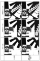
- Figure 10 shows the results of spatial noise removal processing on time-series image data containing motion.
- Figure 10 shows input images for frames 0, 30, and 60, as well as images after spatial noise removal processing has been performed on each input image.
- spatial noise reduction reduces noise but blurs edges.
- the image after spatial noise reduction is only used to determine whether or not there is an afterimage in the image after temporal noise reduction, so it does not affect image quality.
- the output value determination unit 29 performs an output value determination process for the target frame (step A3).
- the output value determination unit 29 determines the output value for the target frame based on the image after the temporal noise removal process for the target frame and the image after the spatial noise removal process for the target frame.
- the output value determination unit 29 sets a pixel to be processed for a target frame (step A11).
- the output value determination unit 29 calculates the absolute value of the difference between the image after the temporal noise removal process and the image after the spatial noise removal process for the pixel to be processed (step A12).
- the output value determination unit 29 determines, for a pixel to be processed, the absolute value of the difference between the output pixel value T n after the temporal noise removal process and the output pixel value S n after the spatial noise removal process, shifted 4 bits to the right, as diff2.
- diff2 can take a value from 0 to 255.
- bit shift is a process for changing the range (width) that diff2 can take. Even after the bit shift, diff2 still indicates the magnitude of the absolute value of the difference between the output pixel value T n after the temporal noise removal process and the output pixel value S n after the spatial noise removal process.
- the output value determination unit 29 determines whether diff2 is equal to or less than the threshold th2 for the pixel being processed (step A13).
- the output value determination unit 29 sets the output pixel value T n after the temporal noise removal process as the output pixel value O n . That is, the output value determination unit 29 outputs the pixel value of the image after the temporal noise removal process (step A14). This removes the temporal noise.
- the output value determination unit 29 sets the input pixel value I n to the output pixel value O n . That is, the output value determination unit 29 outputs the pixel value of the pixel to be processed in the target frame as is (step A15). If diff2 is greater than the threshold th2, the output value determination unit 29 determines that an afterimage exists in the image after the temporal noise removal process, and outputs the input pixel value I n as is to prevent an afterimage from occurring.
- step A16 the output value determination unit 29 judges whether or not the processing has been completed for all pixels in the target frame (step A16). If there is a pixel in the target frame for which processing has not been completed (step A16; NO), the process returns to step A11. The output value determination unit 29 repeats the process for another pixel. In step A16, if the processing has been completed for all pixels in the target frame (step A16; YES), the output value determination processing ends.
- the control unit 21 causes the display unit 23 to display the processed images.
- the control unit 21 causes the display unit 23 to display the processed time-series images as moving images.
- the control unit 21 may also cause the display unit 23 to display the processed time-series images on a frame-by-frame basis.
- Figure 12 shows an image after performing temporal noise removal processing on stationary time-series image data, and the final output image.
- the output image is an image in which the pixel value of the image after temporal noise removal processing or the input pixel value of the target frame is selected for each pixel in the output value determination process.
- FIG. 13A For time-series image data with no motion, the upper left pixel of each frame image is set as the target pixel 31 as shown in FIG. 13A.
- 13B shows the change over time of the input pixel value I n and the output pixel value O n that is finally output by image processing for the target pixel 31.
- the horizontal axis represents the frame number
- the vertical axis represents the pixel value.
- Figure 13C shows the standard deviation of the input pixel values I n and the standard deviation of the output pixel values O n in frames 50 to 149 shown in Figure 13B.
- the standard deviation of the pixel values changes from "362.3" before processing to "54.3" after processing. In other words, it can be seen that the noise level has improved.
- FIG. 14 shows an image after time noise removal processing is performed on time-series image data containing motion, and an output image that is finally output. As shown in FIGS. 12 and 14, the image processing has been performed to remove time noise from the output image while avoiding the occurrence of afterimages.
- the output value determination unit 29 of the image processing device 20 calculates the absolute value of the difference between the pixel value of the image after temporal noise removal processing and the pixel value of the image after spatial noise removal processing for each pixel of the target frame. If the absolute value of the difference is equal to or less than a predetermined value, the output value determination unit 29 outputs the pixel value of the image after temporal noise removal processing. On the other hand, if the absolute value of the difference is greater than the predetermined value, the output value determination unit 29 outputs the pixel value of the target frame.
- the output value determination unit 29 determines that an afterimage will occur due to the temporal noise removal processing, and adopts the input pixel value. Therefore, the image processing device 20 can improve image quality while avoiding side effects caused by the removal of temporal noise.
- the image processing device 20 has a simple configuration and can perform high-performance correction.
- the temporal noise removal unit 27 uses the image after the temporal noise removal process generated for the frame immediately before the target frame for the temporal noise removal process of the target frame. This allows the temporal noise removal unit 27 to output an image equivalent to the average of multiple frames going back in time.
- the spatial noise removal unit 28 can take the average of each pixel of the target frame and its surrounding pixels. This allows the spatial noise removal unit 28 to smooth pixel values within the same frame and remove noise.
- the image quality of the density values that represent the density of the image can be improved while avoiding side effects caused by removing time noise.
- Modification 1 Next, Modification 1 will be described, focusing on the differences from the above embodiment.
- the image processing system 100 in the first modification differs from the above embodiment in the method of temporal noise removal processing.
- the processing other than the temporal noise removal processing is the same as in the above embodiment.
- the temporal noise removal unit 27 of the image processing device 20 performs a temporal noise removal process on each of a plurality of frames constituting a time-series image.
- the temporal noise removal process is a process of taking an average of a target frame and a predetermined number of frames prior to the target frame.
- the temporal noise removal unit 27 may take an average by changing the weighting for each frame (weighted average). In the first modification, both the input pixel value and the output pixel value in the image processing are 12 bits long (0 to 4095).
- the time noise removal unit 27 performs the following process for each pixel in the image.
- the input pixel value of the current frame (target frame) is defined as In .
- the output pixel value after the temporal noise removal process of the current frame is denoted by T n
- the output pixel value after the temporal noise removal process of the previous frame is denoted by T n-1 .
- the temporal noise removal unit 27 holds the output pixel value T n-1 after the temporal noise removal process of the previous frame in memory.
- diff3 can take a value from 0 to 255.
- bit shift is a process for changing the range (width) that diff3 can take. Even after the bit shift, diff3 still indicates the magnitude of the absolute value of the difference between the input pixel value I n of the current frame and the output pixel value T n-1 after the temporal noise removal process of the previous frame.
- the temporal noise remover 27 When diff3 is equal to or smaller than a threshold value th3, the temporal noise remover 27 outputs the average value of pixel values of the past 40 frames. Note that the number of frames used to take the average is not limited to 40 and can be changed as appropriate. If diff3 is greater than the threshold th3, the temporal noise remover 27 outputs the input pixel value In as is.
- the upper left pixel is set as a target pixel 31 as shown in FIG. 15A.
- 15B shows changes over time in the input pixel value In , the average value of the past 30 frames, and the average value of the past 40 frames for the target pixel 31.
- the horizontal axis represents the frame number
- the vertical axis represents the pixel value.
- Fig. 15C shows the standard deviation of the input pixel values In in frames 50 to 149 shown in Fig. 15B, the standard deviation of the average value of the past 30 frames, and the standard deviation of the average value of the past 40 frames.
- the standard deviation of the output pixel values when the average of the past 40 frames is taken as the temporal noise removal process is "51.8". This is close to the standard deviation of the output pixel values after the temporal noise removal process in the above embodiment, "54.3" (see Fig. 5C).
- the temporal noise removal unit 27 takes the average of the target frame and a predetermined number of frames prior to the target frame. This allows the temporal noise removal unit 27 to smooth pixel values in the time direction and remove temporal noise with a simple calculation.
- the formulas (1) and (2) used in calculating the output pixel value Tn after the temporal noise removal process of the current frame are the same as those in the above embodiment.
- the function param(diff) shown in FIG. 16 is used instead of the function param(diff) shown in FIG.
- the param(diff) shown in Fig. 16 is param max when diff is equal to or less than the threshold th4, and is 0 when diff is greater than the threshold th5.
- two thresholds th4 and th5 are set in param(diff) used in the temporal noise removal process, allowing the temporal noise removal level to change smoothly.
- Modification 3 Next, Modification 3 will be described, focusing on the differences from the above embodiment.
- the image processing system 100 in the third modification differs from the above embodiment in the method of spatial noise removal processing.
- the processing other than the spatial noise removal processing is the same as in the above embodiment.
- the spatial noise elimination unit 28 of the image processing device 20 is configured with a hardware circuit such as an FPGA.
- the spatial noise elimination unit 28 includes a line memory that stores pixel values for a predetermined number of lines of a target frame.
- the direction of the lines in the image is the horizontal direction.
- the spatial noise removal unit 28 calculates, for each pixel in the target frame, the average of that pixel and its surrounding pixels.
- the range of surrounding pixels in a direction parallel to the lines (horizontal direction) is greater than the range of surrounding pixels in a direction perpendicular to the lines (vertical direction), i.e. the spatial filter has more pixels in the horizontal direction than in the vertical direction.
- FIG. 17 shows an example of a spatial filter (11 ⁇ 3) used in the spatial noise removal process of Modification 3.
- Modification 3 uses a horizontally long spatial filter. Let W(i,j) be the weighting coefficient at each position in the filter.
- the input pixel value at a pixel position (x, y) in the current frame (target frame) is defined as I n (x, y).
- the output pixel value S n (x, y) after the spatial noise removal process at the pixel position (x, y) is calculated by the following equation (8):
- 33 (11 ⁇ 3) pixel values are averaged.
- a spatial filter in which the number of pixels in the horizontal direction is greater than the number of pixels in the vertical direction is used for the spatial noise removal process. This makes it possible to reduce the number of lines for which the line memory holds data when implementing the spatial noise removal unit 28 using an FPGA or the like, thereby reducing the capacity of the line memory.
- a spatial filter of 11 x 3 (33 pixels) is used, but a spatial filter of a size close to the 7 x 7 (49 pixels) shown in FIG. 7 may be used.
- the spatial filter may be 15 x 3 (45 pixels).
- the spatial noise removal unit 28 of the image processing device 20 performs spatial noise removal processing on each of the multiple frames that make up the time-series image.
- the spatial noise removal processing is a process in which, for each pixel of the target frame, which is a Bayer image, the average of that pixel and the surrounding pixels of the same color as that pixel is taken.
- a Bayer image is an image that contains the luminance values output from each image sensor 13 (sensor) as is. In other words, each pixel in a Bayer image contains only one of the R, G or B information.
- FIG. 18A shows an example of a Bayer array.
- An example of a spatial filter for a Bayer image is shown in Figure 18B.
- W(i,j) be the weighting coefficient at each position in the filter.
- the input pixel value at a pixel position (x, y) in the current frame (target frame) is defined as I n (x, y).
- the output pixel value S n (x, y) after the spatial noise removal process at the pixel position (x, y) is determined by the formula (9).
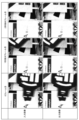
- Figures 19 and 20 show examples of input images and output images for each input image displayed as Bayer images.
- the output image is the final image output as a result of image processing performed on the input image.
- pixel values corresponding to different colors (R, G, or B) are displayed for each pixel.
- Figure 19 is an example when stationary time-series image data is used.
- Figure 20 is an example when stationary time-series image data is used.
- the input image and the output image shown in Fig. 19 and Fig. 20 are colorized, respectively, and are shown in Fig. 21 and Fig. 22.
- Colorization refers to the process of interpolating a color not present in each pixel from neighboring pixels and expressing each pixel as a combination of RGB (demosaic processing). Although false colors may occur when a Bayer image is colorized, the false colors can be suppressed as a result of image processing.
- pixels with movement are output without undergoing temporal noise removal processing, so that side effects due to the removal of temporal noise can be avoided.
- they are shown in monochrome.
- the spatial noise removal unit 28 performs spatial noise removal processing by taking the average of each pixel of the Bayer image, the pixel in question, and the surrounding pixels of the same color as the pixel in question. Since the spatial noise removal unit 28 takes the average of the same color among R, G, and B, it is possible to remove spatial noise for each color of R, G, and B.
- the fifth modification will be described, focusing on the differences from the above embodiment.
- the pixel values correspond to density values, but in the image processing system 100 in modified example 5, the pixel values of the time-series images are numerical values representing distances.
- the pixel values of the image data processed by the image processing device 20 indicate the distance to the object corresponding to each pixel.
- the camera 10 is assumed to be a twin-lens stereo camera.
- the control unit 21 of the image processing device 20 calculates the parallax for an object in two images captured by the two cameras, and calculates the distance from the camera 10 to the object.
- the control unit 21 calculates the parallax and calculates the distance value using the method described in JP 2012-109788 A.
- the signal processing unit 14 of the camera 10 may calculate the distance from the camera 10 to the object.
- the control unit 21 of the image processing device 20 may acquire an image in which the distance values obtained by scanning with a laser are used as pixel values.
- the characteristic processes in the above-described embodiment and each of the modified examples may be combined.
- the pixel values of the time-series images are not limited to density values and distance values, and may be values having other meanings.
- the temporal noise removal unit 27 when the temporal noise removal unit 27 generates an image after the temporal noise removal process for a target frame, in addition to the target frame and a frame that precedes the target frame, a frame that follows the target frame in time may also be used.
- the computer-readable medium for storing the programs for executing each process is not limited to the above examples, and portable recording media such as CD-ROMs can also be used.
- a carrier wave can also be used as a medium for providing program data via a communication line.
- the image processing device, image processing method, and program according to the present invention can be used in the technical field of image processing for moving images.
Landscapes
- Engineering & Computer Science (AREA)
- Physics & Mathematics (AREA)
- General Physics & Mathematics (AREA)
- Theoretical Computer Science (AREA)
- Multimedia (AREA)
- Signal Processing (AREA)
- Image Processing (AREA)
- Picture Signal Circuits (AREA)
Priority Applications (2)
| Application Number | Priority Date | Filing Date | Title |
|---|---|---|---|
| EP24788411.7A EP4697696A4 (en) | 2023-04-12 | 2024-02-14 | IMAGE PROCESSING DEVICE, IMAGE PROCESS AND PROGRAM |
| JP2025513806A JPWO2024214381A1 (https=) | 2023-04-12 | 2024-02-14 |
Applications Claiming Priority (2)
| Application Number | Priority Date | Filing Date | Title |
|---|---|---|---|
| JP2023064705 | 2023-04-12 | ||
| JP2023-064705 | 2023-04-12 |
Publications (1)
| Publication Number | Publication Date |
|---|---|
| WO2024214381A1 true WO2024214381A1 (ja) | 2024-10-17 |
Family
ID=93059497
Family Applications (1)
| Application Number | Title | Priority Date | Filing Date |
|---|---|---|---|
| PCT/JP2024/004990 Ceased WO2024214381A1 (ja) | 2023-04-12 | 2024-02-14 | 画像処理装置、画像処理方法及びプログラム |
Country Status (3)
| Country | Link |
|---|---|
| EP (1) | EP4697696A4 (https=) |
| JP (1) | JPWO2024214381A1 (https=) |
| WO (1) | WO2024214381A1 (https=) |
Citations (6)
| Publication number | Priority date | Publication date | Assignee | Title |
|---|---|---|---|---|
| JPH09312788A (ja) * | 1996-05-23 | 1997-12-02 | Nippon Hoso Kyokai <Nhk> | 雑音低減回路 |
| JP2005229491A (ja) * | 2004-02-16 | 2005-08-25 | Matsushita Electric Ind Co Ltd | デジタル画像のノイズ除去方法 |
| WO2010073488A1 (ja) * | 2008-12-22 | 2010-07-01 | パナソニック株式会社 | 画像ノイズ除去装置及び方法 |
| JP2012109788A (ja) | 2010-11-17 | 2012-06-07 | Konica Minolta Holdings Inc | 画像処理装置および視差情報生成装置 |
| JP2014158083A (ja) | 2013-02-14 | 2014-08-28 | Mitsubishi Electric Corp | 映像処理装置、映像処理方法、放送受信装置、映像撮影装置、映像蓄積装置及びプログラム |
| US20180061015A1 (en) * | 2015-04-16 | 2018-03-01 | Institute Of Automation Chinese Academy Of Sciences | Video Denoising System Based on Noise Correlation |
Family Cites Families (1)
| Publication number | Priority date | Publication date | Assignee | Title |
|---|---|---|---|---|
| US9041834B2 (en) * | 2012-09-19 | 2015-05-26 | Ziilabs Inc., Ltd. | Systems and methods for reducing noise in video streams |
-
2024
- 2024-02-14 WO PCT/JP2024/004990 patent/WO2024214381A1/ja not_active Ceased
- 2024-02-14 EP EP24788411.7A patent/EP4697696A4/en active Pending
- 2024-02-14 JP JP2025513806A patent/JPWO2024214381A1/ja active Pending
Patent Citations (6)
| Publication number | Priority date | Publication date | Assignee | Title |
|---|---|---|---|---|
| JPH09312788A (ja) * | 1996-05-23 | 1997-12-02 | Nippon Hoso Kyokai <Nhk> | 雑音低減回路 |
| JP2005229491A (ja) * | 2004-02-16 | 2005-08-25 | Matsushita Electric Ind Co Ltd | デジタル画像のノイズ除去方法 |
| WO2010073488A1 (ja) * | 2008-12-22 | 2010-07-01 | パナソニック株式会社 | 画像ノイズ除去装置及び方法 |
| JP2012109788A (ja) | 2010-11-17 | 2012-06-07 | Konica Minolta Holdings Inc | 画像処理装置および視差情報生成装置 |
| JP2014158083A (ja) | 2013-02-14 | 2014-08-28 | Mitsubishi Electric Corp | 映像処理装置、映像処理方法、放送受信装置、映像撮影装置、映像蓄積装置及びプログラム |
| US20180061015A1 (en) * | 2015-04-16 | 2018-03-01 | Institute Of Automation Chinese Academy Of Sciences | Video Denoising System Based on Noise Correlation |
Non-Patent Citations (1)
| Title |
|---|
| See also references of EP4697696A1 |
Also Published As
| Publication number | Publication date |
|---|---|
| JPWO2024214381A1 (https=) | 2024-10-17 |
| EP4697696A1 (en) | 2026-02-18 |
| EP4697696A4 (en) | 2026-04-22 |
Similar Documents
| Publication | Publication Date | Title |
|---|---|---|
| US11265490B2 (en) | Systems and methods of spatiotemporal image noise reduction for multispectral image data | |
| US9615039B2 (en) | Systems and methods for reducing noise in video streams | |
| US9202263B2 (en) | System and method for spatio video image enhancement | |
| US20100067818A1 (en) | System and method for high quality image and video upscaling | |
| US8675102B2 (en) | Real time denoising of video | |
| JP6160292B2 (ja) | 画像補正装置、撮像装置及び画像補正用コンピュータプログラム | |
| US20170256067A1 (en) | Image processing device, image processing method, and solid-state imaging device | |
| KR20120112051A (ko) | 화상 처리 장치, 화상 처리 방법 및 프로그램 | |
| US20200219229A1 (en) | Edge-Aware Upscaling for Improved Screen Content Quality | |
| JP6087612B2 (ja) | 画像処理装置および画像処理方法 | |
| JP2014021928A (ja) | 画像処理装置、画像処理方法およびプログラム | |
| US9215353B2 (en) | Image processing device, image processing method, image display device, and image display method | |
| JP2013041565A (ja) | 画像処理装置、画像表示装置、画像処理方法、コンピュータプログラム及び記憶媒体 | |
| CN1893618B (zh) | 用于处理拜耳模式数字彩色视频信号的方法和装置 | |
| CN103685858A (zh) | 视频实时处理的方法及设备 | |
| JP2007323635A (ja) | ビデオ・イメージの再帰的フィルタリング | |
| CN106027943B (zh) | 一种视频去隔行方法 | |
| WO2024214381A1 (ja) | 画像処理装置、画像処理方法及びプログラム | |
| US11062424B2 (en) | Systems and methods for motion adaptive filtering as pre-process to video encoding | |
| KR100913890B1 (ko) | 움직임 적응 시공간 디인터레이싱 방법 | |
| JP6708131B2 (ja) | 映像処理装置、映像処理方法及びプログラム | |
| KR102470242B1 (ko) | 영상 처리 장치, 영상 처리 방법, 및 프로그램 | |
| JP2019045981A (ja) | 画像処理装置、画像処理方法及びプログラム | |
| RU2308817C1 (ru) | Способ и устройство масштабирования динамического видеоизображения | |
| JP2014007658A (ja) | 動きベクトル導出装置、方法およびプログラム |
Legal Events
| Date | Code | Title | Description |
|---|---|---|---|
| 121 | Ep: the epo has been informed by wipo that ep was designated in this application |
Ref document number: 24788411 Country of ref document: EP Kind code of ref document: A1 |
|
| ENP | Entry into the national phase |
Ref document number: 2025513806 Country of ref document: JP Kind code of ref document: A |
|
| WWE | Wipo information: entry into national phase |
Ref document number: 2025513806 Country of ref document: JP |
|
| WWE | Wipo information: entry into national phase |
Ref document number: 2024788411 Country of ref document: EP |
|
| NENP | Non-entry into the national phase |
Ref country code: DE |
|
| ENP | Entry into the national phase |
Ref document number: 2024788411 Country of ref document: EP Effective date: 20251112 |
|
| ENP | Entry into the national phase |
Ref document number: 2024788411 Country of ref document: EP Effective date: 20251112 |
|
| ENP | Entry into the national phase |
Ref document number: 2024788411 Country of ref document: EP Effective date: 20251112 |
|
| ENP | Entry into the national phase |
Ref document number: 2024788411 Country of ref document: EP Effective date: 20251112 |
|
| ENP | Entry into the national phase |
Ref document number: 2024788411 Country of ref document: EP Effective date: 20251112 |
|
| ENP | Entry into the national phase |
Ref document number: 2024788411 Country of ref document: EP Effective date: 20251112 |
|
| ENP | Entry into the national phase |
Ref document number: 2024788411 Country of ref document: EP Effective date: 20251112 |
|
| ENP | Entry into the national phase |
Ref document number: 2024788411 Country of ref document: EP Effective date: 20251112 |
|
| ENP | Entry into the national phase |
Ref document number: 2024788411 Country of ref document: EP Effective date: 20251112 |
|
| WWP | Wipo information: published in national office |
Ref document number: 2024788411 Country of ref document: EP |