WO2024214253A1 - 血液検査用補助具 - Google Patents
血液検査用補助具 Download PDFInfo
- Publication number
- WO2024214253A1 WO2024214253A1 PCT/JP2023/015055 JP2023015055W WO2024214253A1 WO 2024214253 A1 WO2024214253 A1 WO 2024214253A1 JP 2023015055 W JP2023015055 W JP 2023015055W WO 2024214253 A1 WO2024214253 A1 WO 2024214253A1
- Authority
- WO
- WIPO (PCT)
- Prior art keywords
- blood
- substrate
- base material
- pool
- blood test
- Prior art date
- Legal status (The legal status is an assumption and is not a legal conclusion. Google has not performed a legal analysis and makes no representation as to the accuracy of the status listed.)
- Ceased
Links
Images






Classifications
-
- G—PHYSICS
- G01—MEASURING; TESTING
- G01N—INVESTIGATING OR ANALYSING MATERIALS BY DETERMINING THEIR CHEMICAL OR PHYSICAL PROPERTIES
- G01N33/00—Investigating or analysing materials by specific methods not covered by groups G01N1/00 - G01N31/00
- G01N33/48—Biological material, e.g. blood, urine; Haemocytometers
- G01N33/50—Chemical analysis of biological material, e.g. blood, urine; Testing involving biospecific ligand binding methods; Immunological testing
- G01N33/52—Use of compounds or compositions for colorimetric, spectrophotometric or fluorometric investigation, e.g. use of reagent paper and including single- and multilayer analytical elements
Definitions
- the present invention relates to a blood test aid used in blood tests to measure the presence or concentration of a specific substance in blood.
- Blood tests that analyze the presence or concentration of specific substances in blood are widely used to diagnose a subject's health condition. For example, by analyzing the content of various components in the plasma in the blood, it is possible to diagnose the subject's organ function, etc.
- the blood sample is separated into liquid components, such as plasma or serum, and solid components, such as cells, using a centrifuge or suction/pressurization pump.
- a centrifuge or suction/pressurization pump Normally, a certain amount of blood (e.g., 5 mL or more) is required to run the blood through a centrifuge, so a doctor, nurse, or clinical laboratory technician must draw blood from the subject.
- typical blood tests can only be performed at medical institutions or specialized testing institutions that are equipped with expensive analytical equipment such as centrifuges and the power supplies to operate them.
- the burden on medical professionals who draw the blood is also great. In other words, typical blood tests are a heavy burden not only on the subject but also on medical institutions, and are expensive.
- Patent document 1 discloses a reagent strip that includes a test pad formed from an anisotropic membrane that contains a color-developing reagent system specific to the analyte and has a side with relatively small holes that define a test surface and an opposite side with relatively large holes that define a sample receiving surface, and a porous sample transport medium attached to the sample receiving surface of the test pad, the transport medium being capable of receiving a whole blood sample and transporting a detectable portion of the sample to the sample receiving surface.
- the amount of plasma is too much, the plasma will overflow from the reagent phase and wrap around the surface from the sides of the reagent phase, resulting in an uneven reaction.
- an appropriate amount of blood needs to be added to the testing device.
- the present invention was made in consideration of the above, and aims to provide a blood testing aid that allows an appropriate amount of blood to be added to a blood testing device with simple operations.
- the blood test auxiliary tool of one aspect of the present invention is a blood test auxiliary tool that assists in tests using a blood test device
- the blood test device has a first substrate on which a blood addition section, which is an opening through which blood is added, is formed, a second substrate on which an observation window, which is an opening for observing a color reaction, is formed, and a plasma separation membrane and a dry reagent phase are arranged by being laminated between the first and second substrates, and is provided with a first base material on which a pool in which blood is placed is formed, and a second substrate that can be superimposed on the first substrate, and is provided with a guide on the side facing the pool that indicates the position where the blood test device is fixed to the second substrate, and is provided with an opening that exposes the observation window when the blood test device is fixed in accordance with the guide.
- At least one of the first and second substrates may be provided with a support portion that ensures a gap of a predetermined height between the pool side surface of the pool and the fixing surface of the blood test device on the second substrate when the first substrate and the second substrate are superimposed.
- a protrusion that protrudes beyond the pool side surface may be formed on the first base material near the pool.
- the first substrate and the second substrate may be formed from a continuous sheet-like member, and the first substrate and the second substrate may be overlapped by folding the first substrate and the second substrate at the boundary line between them.
- one of the first and second base materials may be provided with a convex portion with a protrusion formed on a wall surface
- the other of the first and second base materials may be provided with a concave space into which the convex portion can fit
- a depression may be formed in the wall surface of the space at a position corresponding to the protrusion, and by fitting the convex portion into the space, the protrusion may fit into the depression, and the first base material and the second base material may be fixed in a superimposed state.
- the present invention by fixing a blood testing device to a blood testing auxiliary tool and placing blood in a pool, it is possible to add an appropriate amount of blood to the blood testing device with a simple operation.
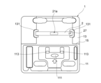
- FIG. 1 is a plan view showing the inner surface side (unfolded state) of a blood test auxiliary device according to an embodiment of the present invention.
- FIG. 2 is an end view taken along lines AA to FF shown in FIG. 1.
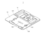
- FIG. 2 is a perspective view showing the inner surface side (unfolded state) of the blood test auxiliary device according to the embodiment of the present invention.
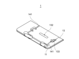
- 1 is a perspective view showing the outer surface side (in an unfolded state) of a blood test auxiliary device according to an embodiment of the present invention.
- FIG. FIG. 1 is a perspective view showing a blood test auxiliary device (in a folded state) according to an embodiment of the present invention.
- FIG. 2 is an enlarged perspective view (blood application part side) illustrating a blood test device used in an embodiment of the present invention.
- FIG. 2 is an enlarged perspective view (observation window side) illustrating a blood test device used in an embodiment of the present invention.
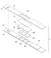
- 1 is an enlarged exploded perspective view illustrating a blood testing device used in an embodiment of the present invention.
- 1A to 1C are schematic diagrams illustrating a method of using the blood test auxiliary device according to an embodiment of the present invention.
- 1A to 1C are schematic diagrams illustrating a method of using the blood test auxiliary device according to an embodiment of the present invention.
- 1A to 1C are schematic diagrams illustrating a method of using the blood test auxiliary device according to an embodiment of the present invention.
- 1A to 1C are schematic diagrams illustrating a method of using the blood test auxiliary device according to an embodiment of the present invention.
- 1 is a graph showing the colorimetric sensitivity of blood glucose in an example.
- 1 is a graph showing the colorimetric sensitivity of neutral fats in an example.
- 1 is a graph showing the colorimetric sensitivity of total cholesterol in an example.
- 14 is a graph showing blood glucose concentrations corresponding to the colorimetric sensitivities shown in FIG. 13.
- 15 is a graph showing the concentration of neutral fats corresponding to the colorimetric sensitivities shown in FIG. 14 .
- FIG. 16 is a graph showing the concentration of total cholesterol corresponding to the colorimetric sensitivity shown in FIG. 15.
- FIG. 1 is a plan view showing the inner side (unfolded state) of the blood test auxiliary according to the embodiment of the present invention.
- FIG. 2 is an end view of each of the lines A-A to F-F shown in FIG. 1.
- FIG. 2(a) shows the A-A end face of FIG. 1
- FIG. 2(b) shows the B-B end face of FIG. 1
- FIG. 2(c) shows the C-C end face of FIG. 1
- FIG. 2(d) shows the D-D end face of FIG. 1
- FIG. 2(e) shows the E1-E2-E3-E4 end face of FIG. 1
- FIG. 2(f) shows the F-F end face of FIG. 1.
- FIG. 2(a) shows the A-A end face of FIG. 1
- FIG. 2(b) shows the B-B end face of FIG. 1
- FIG. 2(c) shows the C-C end face of FIG. 1
- FIG. 2(d) shows the D-D end face of
- FIG. 3 is a perspective view showing the inner side (unfolded state) of the blood test auxiliary.
- FIG. 4 is a perspective view showing the outer side (unfolded state) of the blood test auxiliary.
- FIG. 5 is a perspective view showing the blood test auxiliary (folded state).
- the blood test auxiliary device (hereinafter also simply referred to as the auxiliary device) 1 is an instrument that assists in testing blood that has been self-drawn by a subject.
- the auxiliary device 1 comprises a lower substrate (first substrate) 11 and an upper substrate (second substrate) 12 that can be stacked on top of each other.
- first substrate first substrate
- second substrate upper substrate
- the side that becomes the outside when the lower substrate 11 and the upper substrate 13 are stacked on top of each other when the auxiliary device 1 is in use (see Figure 5) is referred to as the outer side, and the side that becomes the inside is referred to as the inner side.
- the detailed configuration of the auxiliary device 1 will be described later.
- Fig. 6 is a perspective view (blood addition part side) illustrating a blood test device used in an embodiment of the present invention.
- Fig. 7 is a perspective view (observation window side) of the same blood test device.
- Fig. 8 is an exploded perspective view of the same blood test device.
- the blood testing device 2 shown in Figures 6 to 8 is intended to measure the presence or concentration of a specific substance contained in plasma based on a color reaction that occurs in a dry reagent phase by contacting the plasma separated from blood with a dry reagent phase impregnated with a reagent.
- Measurable test items are not particularly limited as long as they are components contained in plasma and show a color reaction with a specific reagent.
- Specific examples of test items include AST, ALT, ⁇ -GT, neutral fats, HDL cholesterol, LDL cholesterol, total cholesterol, blood glucose, HbA1c, etc., as well as minerals such as zinc and magnesium.
- the testing device 2 comprises a first substrate 21 and a second substrate 22 arranged opposite each other, and a diffusion layer 23, a plasma separation section 24, and reagent phases 25a-25c arranged and stacked between the first substrate 21 and the second substrate 22.
- the number of testable items may be one or two, or four or more.
- the first substrate 21 and the second substrate 22 are formed from a thin sheet material.
- the material for the first substrate 21 and the second substrate 22 may be a resin material such as PET (polyethylene terephthalate) or cardboard with a water-repellent finish, as long as it can maintain the shape of the testing device 2 and is not permeated by the blood or plasma sample or reacts with these liquids.
- the first substrate 21 is formed with a blood addition section 21a, which is an opening through which the blood sample is added.
- the shape of the blood addition section 21a is rectangular, but this shape is not particularly limited, and various shapes such as an elliptical or oval shape can be used as long as the shape allows for the addition of blood.
- the second substrate 22 has observation windows 22a-22c, which are openings for observing the color reactions of the reagent phases 25a-25c, respectively.
- the number of these observation windows 22a-22c is set according to the number of test items (i.e., the number of reagent phases 25a-25c).
- the shape of each observation window 22a-22c is square, but this shape is not particularly limited and may be circular, elliptical, or the like.
- alignment openings 27 may be formed in corresponding locations on the first substrate 21 and the second substrate 22, respectively.
- the first substrate 21 and the second substrate 22 may be formed from two plates separated from each other as shown in FIG. 8, or may be formed by bending a single elongated plate.
- a spacer 26 may be placed between the first substrate 21 and the second substrate 22 to form a space 20a of a height sufficient to accommodate the diffusion layer 23, the plasma separation section 24, and the reagent phases 25a to 25c.
- the diffusion layer 23 is formed from a material made of hydrophilic fibers woven into a sheet, and is arranged so that a portion of it is exposed from the blood addition section 21a provided on the first substrate 21.
- the diffusion layer 23 quickly guides the blood added to the blood addition section 21a over a wide range in the planar direction by capillary action, and acts to uniformly soak into one side of the plasma separation section 24.
- the diffusion layer 23 can be, for example, a plain woven hydrophilic polyester material.
- the plasma separation section 24 is formed from a porous sheet material, trapping cellular components from the blood that has soaked into one side and separating the plasma by allowing liquid components to pass through in the thickness direction of the membrane.
- a porous polymer membrane such as a polysulfone (PS) membrane or an asymmetric PS membrane can be used as the plasma separation section 24.
- the reagent phases 25a-25c are dry reagent phases in which filter paper (such as chromatography paper) is impregnated with a reagent corresponding to the test item and dried, and are arranged so that a portion of them is exposed from each of the observation windows 22a-22c.
- the reagent phases 25a-25c react with a specific substance contained in the plasma that has passed through the plasma separation section 24 and become colored. This color reaction can be visually observed from the observation window 22a-22c side as the plasma has sufficiently permeated the reagent phases 25a-25c.
- the diffusion layer 23, the plasma separation section 24, and the reagent phases 25a to 25c are attached to the first substrate 21 or the second substrate 22 using double-sided tape or the like.
- the first substrate 21 and the second substrate 22 are also attached to each other using double-sided tape or the like, or to each other via the spacer 26.
- the lower base material 11 and the upper base material 13 of the support tool 1 are formed by vacuum molding using a resin material such as polyethylene terephthalate (PET) or polyethylene (PE).
- PET polyethylene terephthalate
- PE polyethylene
- the method and material for forming the lower base material 11 and the upper base material 13 are not limited to this.
- a composite material of pulp and resin, or a material obtained by subjecting cardboard to a water-repellent treatment may be used, or the lower base material 11 and the upper base material 13 may be formed using a press process or a pulp molding technique.
- the auxiliary device 1 is configured such that the lower base material 11 and the upper base material 13 are integrally formed and are folded at the boundary line 15 between the lower base material 11 and the upper base material 13 so that the two are superimposed.
- the lower base material 11 and the upper base material 13 may also be formed separately from each other.
- a pool 111 in which blood is placed is formed on the inner surface side of the lower substrate 11.
- the capacity of the pool 111 is determined based on the appropriate amount of blood to be added to the testing device 2 (for example, 30 ⁇ L to 40 ⁇ L) so that when the pool 111 is filled with blood such that the blood rises slightly above the upper surface of the pool 111 (i.e., the pool side surface 112) due to surface tension, it will be approximately the appropriate amount.
- the size of the opening surface of the pool 111 is preferably the same as or slightly smaller than the blood addition section 21a of the testing device 2. Even if the opening surface of the pool 111 is smaller than the blood addition section 21a, the blood can be widely diffused over the entire surface of the plasma separation section 24 by the diffusion layer 23 by bringing the blood into contact with a part of the blood addition section 21a.
- the shape of the opening surface of the pool 111 may be the same as or different from that of the blood addition section 21a. In this embodiment, the blood addition section 21a is rectangular, whereas the opening surface of the pool 111 is elliptical.
- a protrusion 113 is formed near the pool 111, protruding further inward than the pool side surface 112.
- This protrusion 113 functions as a support that ensures a gap G (see FIG. 2C) of a predetermined height between the pool side surface 112 and the fixing surface 13a of the test device 2 on the upper substrate 12 when the lower substrate 11 and the upper substrate 12 are overlapped.
- the height of this gap G is preferably set to be approximately the same as the thickness of the test device 2 or slightly smaller than the test device 2.
- the blood addition portion 21a of the test device 2 can be brought into contact with the blood placed in the pool 111 without the user applying external force to the holder 1, and the test device 2 can be maintained in a moderately compressed state without being strongly crushed.
- the protrusion 113 can also be used as a guide for the user to check the amount of blood to be added when adding it to the pool 111. Furthermore, a mark (e.g., an arrow) 114 indicating the position of the pool 111 may be placed near the pool 111.
- a mark e.g., an arrow
- a guide 131 is provided on the inner surface of the upper base material 13 (i.e., the side facing the pool 111) to indicate the position where the test device 2 is fixed to the upper base material 13.
- the guide 131 is provided so as to protrude toward the inner surface side beyond the fixing surface 13a of the test device 2.
- the test device 2 can be attached to the blood test device 2 in the appropriate position by abutting the end side of the test device 2 against the inner wall of the guide 131.
- the guide 131 may simply be a printed mark indicating the attachment position of the test device 2.
- the upper base material 13 has an opening 132 that exposes the observation windows 22a to 25c when the inspection device 2 is fixed in place in accordance with the guide 131.
- the upper base material 13 may also have an alignment opening 133 formed therein that corresponds to the alignment opening 27 of the inspection device 2.
- the lower substrate 11 is formed with support portions 115 and 116 that protrude from the floor surface of the lower substrate 11 to the inner side.
- the top surface of the support portion 115 abuts against the floor surface 134 of the upper substrate 13, and the top surface of the support portion 116 abuts against the floor surface 135 of the upper substrate.
- these support portions 115 and 116 can also function as a means for ensuring a gap G of a predetermined height between the pool side surface 112 of the pool 111 provided on the lower substrate 11 and the fixing surface 13a of the testing device 2 on the upper substrate 13.
- both the lower base material 11 and the upper base material 13 may be provided with support parts that protrude to the inner side and abut against each other at the top surface.
- the protrusion part 113 may be omitted, and either or both of the support parts 115 and 116 may be provided. In short, it is sufficient that a gap G is secured between the pool side surface 112 and the fixing surface 13a when the upper base material 13 is superimposed on the lower base material 11.
- the upper substrate 13 has two convex portions 136 that protrude from the floor surface toward the inner side. Protrusions 137 are formed on the outer wall surfaces of these convex portions 136. Meanwhile, the lower substrate 11 has two convex portions 121 that protrude from the floor surface. The spaces between these convex portions 121 and the outer periphery 120 form spaces 122 into which the two convex portions 136 can each fit. In the inner wall surface of the outer periphery 120 and the outer wall surface of the convex portions 121 that form each space 122, depressions 123, 124 are formed at positions that correspond to the protrusions 137 of the upper substrate 13.
- the protrusions 137 on the convex portion 136 side fit into the recesses 123 and 124 on the space 122 side, and the lower substrate 11 and the upper substrate 13 can be fixed in a closed state.
- a convex portion with a protrusion on the outer wall surface may be provided on the lower base material 11, and a space with a recess formed on the wall surface may be provided on the upper base material 13.
- a guide 141 may be formed on the outer surface of the upper substrate 13, protruding toward the surface on which the opening 132 is formed.
- the guide 141 can be used to align the opening 132 with a card-shaped color sample (color comparison card) used when observing the color reaction of the reagent phases 25a to 25c.
- the test items corresponding to the reagent phases 25a to 25c exposed from the opening 132 may be displayed around the opening 132 on the outer surface of the upper substrate 13 by printing or stickers.
- FIG. 12 are schematic diagrams for explaining a method of using the blood test auxiliary device according to this embodiment.
- TCHD total cholesterol
- TG triglycerides
- GLU blood glucose
- the test device 2 is attached to the inner surface of the upper base material 13 of the auxiliary tool 1.
- the alignment opening 27 of the test device 2 is aligned with the alignment opening 133 of the upper base material 13, the blood addition section 21a is faced to the inner surface, and the test device 2 is placed inside the guide 131.
- the means for attaching the test device 2 and for example, double-sided tape can be used.
- the subject places blood collected by puncturing his/her fingertip or the like in the pool 111.
- the blood can be transferred to the pool 111 by directly contacting the blood pool formed on the fingertip or the like with the pool 111.
- the amount of blood is such that the surface of the blood 3 rises above the pool side surface 112 due to surface tension.
- the subject can check whether the amount of blood 3 is sufficient by using the protrusion 113 as a guide.
- FIG. 10(b) if the surface of the blood 3 is lower than the pool side surface 112, the blood 3 cannot come into contact with the diffusion layer 23 inside the blood addition section 21a, and the amount of blood may be insufficient.
- FIG. 10(c) even if the surface of the blood 3 is higher than the pool side surface 112, if the entire pool 111 is not filled with blood, the amount of blood may still be insufficient.
- the upper base material 13 is folded at the boundary line 15 and overlapped with the lower base material 11.
- the convex portion 136 of the upper base material 13 is fitted into the space 122 of the lower base material 11. This allows the assistive device 1 to be kept closed without the subject having to hold it down.
- the height of the gap G between the pool side surface 112 of the lower substrate 11 and the fixing surface 13a of the upper substrate 13 is approximately the same as the thickness of the test device 2. Therefore, by closing the auxiliary tool 1, the first substrate 21 of the test device 2 is brought into almost contact with the pool side surface 112. As a result, the surface of the blood 3 filling the pool 111 comes into contact with the diffusion layer 23 inside the blood addition section 21a. As a result, almost all of the blood 3 in the pool 111 is sucked in by capillary action and added to the test device 2.
- the auxiliary tool 1 when the auxiliary tool 1 is closed, it is acceptable for there to be a small gap between the test device 2 and the pool side surface 112.
- the blood 3 fills the pool 111 in a raised state due to surface tension (see FIG. 10(a)), so if a portion of the surface of the blood 3 can come into contact with the diffusion layer 23, the blood will be sucked in from that point.
- the blood that has spread over the entire surface of the diffusion layer 23 soaks into the plasma separation section 24.
- the plasma separated by the plasma separation section 24 then soaks into the reagent phases 25a-25c.
- the color of the reagent phases 25a-25c in which a color reaction has occurred is compared with a reference color to estimate the concentration of the test item.
- the colorimetric card 4 shown in FIG. 12 can be used to estimate the concentration.
- the colorimetric card 4 displays scales 41-43 consisting of color samples that the reagent phases 25a-25c can show for each test item (for example, total cholesterol (TCHO), triglycerides (TG), blood glucose (GLU)).
- the scales 41-43 display numerical values indicating the concentration of the component corresponding to each color (or the stage corresponding to the concentration).
- openings 44-46 corresponding to the positions of the reagent phases 25a-25c appearing in the opening 132 of the auxiliary tool 1 are formed within the area of each scale 41-43.
- the values displayed on each scale 41 to 43 indicate the concentration (mg/dL) range that can be detected by a simple test in stages. Specifically, the concentration of total cholesterol is shown in seven stages, the concentration of triglycerides is shown in five stages, and the concentration of blood glucose is shown in seven stages.
- the reagent phases 25a to 25c appear in sequence in the openings 44 to 46.
- the subject can visually determine the test results (concentration of each component) by comparing the colors of the reagent phases 25a to 25c that appear in the openings 44 to 46, respectively, with the color samples in the scales 41 to 43.
- the auxiliary tool 1 can be disposed of without opening it. This prevents contamination by the tested blood.
- the test device 2 is fixed to the auxiliary tool 1, blood is placed in the pool 111 of the auxiliary tool 1, and the auxiliary tool 1 is closed to perform the test, making it possible to add an appropriate amount of blood to the blood test device with simple operations.
- a protrusion 113 that protrudes from the pool side surface 112 is provided near the pool 111, so that the subject can use it as a guide for the amount of blood when placing blood in the pool 111.
- the inspection device 2 is attached to the auxiliary tool 1 and inspection is performed, making it easy to handle the inspection device 2.
- the reaction in test device 2 begins by closing auxiliary tool 1, making it easy to control the test time.
- the waiting time from when blood is added to test device 2 until sufficient reaction is observed in reagent phases 25a to 25c can be accurately counted.
- the test device 2 by attaching the test device 2 to the auxiliary tool 1 in accordance with the guide 131, the color reaction of the reagent phases 25a to 25c can be observed from the outer surface of the auxiliary tool 1.
- the support portions 115 and 116 are provided to ensure a gap G of a predetermined height between the pool side surface 112 and the fixing surface 13a, so that the testing device 2 can be held without being crushed.
- the upper substrate 13 can be fixed to the lower substrate 11 and maintained in a closed state by fitting the convex portion 136 with the protrusion 137 formed on the wall surface into the space 122 with the recesses 123, 124 formed on the wall surface. Therefore, contamination of the surroundings by blood can be prevented during the waiting time for the color reaction, during observation using the color comparison card 4, and even at the time of disposal.
- the outer peripheral shape and size of the lower substrate 11 and the upper substrate 13 are the same (see FIG. 5), but the outer peripheral shape or size of the two may be different.
- a notch may be provided in a part of the upper substrate 13.
- the auxiliary tool 1 is placed on a desk, blood is placed in the pool 111, and then the part of the lower substrate 11 corresponding to the notch is pressed to keep the lower substrate 11 horizontal, and the upper substrate 13 is placed over the lower substrate 11. This makes it easier to handle the auxiliary tool 1.
- a tongue protruding outward may be formed on either the lower substrate 11 or the upper substrate 13.
- the tongue can be pressed down to place the upper substrate 13 over the lower substrate 11.
- the tongue can be pinched and placed over the lower substrate 11.
- tongues may be formed on both the lower substrate 11 and the upper substrate 13 at different positions.
- test device 2 An experimental test device having a similar configuration to test device 2 was created, and an experiment was carried out as follows in which the amount of blood placed in auxiliary tool 1 was changed and the colorimetric sensitivity in the reagent phase was measured.
- Reagent phase Material Test paper impregnated with glucose concentration measuring reagents (ingredients: piperazine-1,4-bis(2-ethanesulfonic acid) (PIPES), N-ethyl-N-(2-hydroxy-3-sulfopropyl)-3,5-dimethoxyaniline sodium (DAOS), 4-aminoantipyrine (4-AA), mutarotase, peroxidase (POD), glucose oxidase) and dried.
- PPES glucose concentration measuring reagents
- Plasma separation section Material Asymmetric polysulfone Size: 5 mm (short side of the device) x 10 mm (longitudinal direction of the device), thickness 0.33 mm
- Diffusion layer Material hydrophilic polyester plain weave sheet Size: 5 mm (short side of device) x 10 mm (longitudinal direction of device), thickness 0.12 mm
- Experimental method (1) A blood test device was attached to a specified location on the support tool. (2) Experimental blood (whole blood) was dropped into the pool of the support tool. Three different amounts of blood were used: 30 ⁇ L, 35 ⁇ L, and 40 ⁇ L. In all cases, the surface of the blood was raised above the side of the pool due to surface tension. (3) Five minutes after the auxiliary tool was closed, the reagent phase exposed in the observation window was photographed with an optical camera, and the colorimetric sensitivity of each reagent phase was estimated based on the image. Furthermore, the CV value of the colorimetric sensitivity was calculated. (4) Based on the colorimetric sensitivity, the concentration (mg/dL) of each component was calculated.
- FIG. 13 is a graph showing the colorimetric sensitivity of blood glucose in the example.
- FIG. 14 is a graph showing the colorimetric sensitivity of triglycerides in the example.
- FIG. 15 is a graph showing the colorimetric sensitivity of total cholesterol in the example.
- FIG. 16 is a graph showing the blood glucose concentration corresponding to the colorimetric sensitivity shown in FIG. 13.
- FIG. 17 is a graph showing the triglyceride concentration corresponding to the colorimetric sensitivity shown in FIG. 14.
- FIG. 18 is a graph showing the total cholesterol concentration corresponding to the colorimetric sensitivity shown in FIG. 15.
- the horizontal axis shows the amount of blood dropped into the pool
- the vertical axis shows the colorimetric sensitivity.
- the horizontal axis shows the colorimetric sensitivity
- the vertical axis shows the concentration of each component (mg/dL).
- the CV values of colorimetric sensitivity were 1.61% for blood glucose, 2.42% for triglycerides, and 2.44% for total cholesterol.
- the blood volumes set in the experiment were 30 ⁇ L, 35 ⁇ L (approximately 17% increase), and 40 ⁇ L (approximately 14% increase).
- the colorimetric sensitivity was generally within the range of ⁇ 0.02 regardless of the amount of blood dripped.
- the CV value of the colorimetric sensitivity was within 3% for all components. Therefore, it can be said that the variation in colorimetric sensitivity due to the amount of blood dripped is small.
- the variation in colorimetric sensitivity shown in Figures 13 to 15 does not have a significant effect on the concentration of each component.
- the same level for blood glucose is approximately 80 mg or more and less than 120 mg per dL
- the same level for triglycerides is approximately 70 mg or more and less than 100 mg
- the same level for total cholesterol is approximately 180 mg or more and less than 220 mg.
Landscapes
- Health & Medical Sciences (AREA)
- Life Sciences & Earth Sciences (AREA)
- Hematology (AREA)
- Immunology (AREA)
- Engineering & Computer Science (AREA)
- Urology & Nephrology (AREA)
- Molecular Biology (AREA)
- Chemical & Material Sciences (AREA)
- Biomedical Technology (AREA)
- Physics & Mathematics (AREA)
- Microbiology (AREA)
- Cell Biology (AREA)
- Food Science & Technology (AREA)
- Medicinal Chemistry (AREA)
- Biotechnology (AREA)
- Analytical Chemistry (AREA)
- Biochemistry (AREA)
- General Health & Medical Sciences (AREA)
- General Physics & Mathematics (AREA)
- Pathology (AREA)
- Investigating Or Analysing Biological Materials (AREA)
- Measurement Of The Respiration, Hearing Ability, Form, And Blood Characteristics Of Living Organisms (AREA)
Priority Applications (3)
| Application Number | Priority Date | Filing Date | Title |
|---|---|---|---|
| JP2025513601A JPWO2024214253A1 (https=) | 2023-04-13 | 2023-04-13 | |
| PCT/JP2023/015055 WO2024214253A1 (ja) | 2023-04-13 | 2023-04-13 | 血液検査用補助具 |
| TW113113646A TWI894911B (zh) | 2023-04-13 | 2024-04-12 | 血液檢測用輔助具 |
Applications Claiming Priority (1)
| Application Number | Priority Date | Filing Date | Title |
|---|---|---|---|
| PCT/JP2023/015055 WO2024214253A1 (ja) | 2023-04-13 | 2023-04-13 | 血液検査用補助具 |
Publications (1)
| Publication Number | Publication Date |
|---|---|
| WO2024214253A1 true WO2024214253A1 (ja) | 2024-10-17 |
Family
ID=93059001
Family Applications (1)
| Application Number | Title | Priority Date | Filing Date |
|---|---|---|---|
| PCT/JP2023/015055 Ceased WO2024214253A1 (ja) | 2023-04-13 | 2023-04-13 | 血液検査用補助具 |
Country Status (3)
| Country | Link |
|---|---|
| JP (1) | JPWO2024214253A1 (https=) |
| TW (1) | TWI894911B (https=) |
| WO (1) | WO2024214253A1 (https=) |
Citations (6)
| Publication number | Priority date | Publication date | Assignee | Title |
|---|---|---|---|---|
| JPH04223267A (ja) * | 1990-03-26 | 1992-08-13 | Cascade Medical Inc | 使い捨て試薬ユニット |
| JP2006058093A (ja) * | 2004-08-18 | 2006-03-02 | National Institute For Materials Science | 血液分析装置 |
| JP2008082899A (ja) * | 2006-09-27 | 2008-04-10 | Terumo Corp | 成分測定用チップ |
| JP2012524257A (ja) * | 2009-04-17 | 2012-10-11 | デジタル オプティクス シーオー エルティーディー | 迅速な血球分離が可能な疾病診断用のバイオセンサー |
| JP2015501929A (ja) * | 2011-11-23 | 2015-01-19 | カルマルク スウェーデン エービー | 試験システム構成および試験の方法 |
| JP2016519771A (ja) * | 2013-04-12 | 2016-07-07 | エリューム・ピーティーワイ・リミテッド | ヒトまたは動物の身体用のサンプリングおよび試験デバイス |
Family Cites Families (6)
| Publication number | Priority date | Publication date | Assignee | Title |
|---|---|---|---|---|
| GR1002549B (el) * | 1992-05-12 | 1997-01-28 | Lifescan Inc. | Λωρις εξετασεως με μεταφορικο μεσο δια μεταφορα ρευστου. |
| US7226461B2 (en) * | 2002-04-19 | 2007-06-05 | Pelikan Technologies, Inc. | Method and apparatus for a multi-use body fluid sampling device with sterility barrier release |
| GB201602773D0 (en) * | 2016-02-17 | 2016-03-30 | Orsus Medical Ltd | A method and apparatus for measuring the concentration of target substances in blood |
| CN117912631A (zh) * | 2017-06-15 | 2024-04-19 | 诺和诺德股份有限公司 | 具有适应性靶葡萄糖水平的基础滴定 |
| EP3911222A4 (en) * | 2019-01-17 | 2023-02-01 | SBI Alapharma Canada, Inc. | MODULAR ENDOSCOPIC DISEASE VISUALIZATION SYSTEM |
| US11754824B2 (en) * | 2019-03-26 | 2023-09-12 | Active Medical, BV | Method and apparatus for diagnostic analysis of the function and morphology of microcirculation alterations |
-
2023
- 2023-04-13 WO PCT/JP2023/015055 patent/WO2024214253A1/ja not_active Ceased
- 2023-04-13 JP JP2025513601A patent/JPWO2024214253A1/ja active Pending
-
2024
- 2024-04-12 TW TW113113646A patent/TWI894911B/zh active
Patent Citations (6)
| Publication number | Priority date | Publication date | Assignee | Title |
|---|---|---|---|---|
| JPH04223267A (ja) * | 1990-03-26 | 1992-08-13 | Cascade Medical Inc | 使い捨て試薬ユニット |
| JP2006058093A (ja) * | 2004-08-18 | 2006-03-02 | National Institute For Materials Science | 血液分析装置 |
| JP2008082899A (ja) * | 2006-09-27 | 2008-04-10 | Terumo Corp | 成分測定用チップ |
| JP2012524257A (ja) * | 2009-04-17 | 2012-10-11 | デジタル オプティクス シーオー エルティーディー | 迅速な血球分離が可能な疾病診断用のバイオセンサー |
| JP2015501929A (ja) * | 2011-11-23 | 2015-01-19 | カルマルク スウェーデン エービー | 試験システム構成および試験の方法 |
| JP2016519771A (ja) * | 2013-04-12 | 2016-07-07 | エリューム・ピーティーワイ・リミテッド | ヒトまたは動物の身体用のサンプリングおよび試験デバイス |
Also Published As
| Publication number | Publication date |
|---|---|
| TW202504549A (zh) | 2025-02-01 |
| TWI894911B (zh) | 2025-08-21 |
| JPWO2024214253A1 (https=) | 2024-10-17 |
Similar Documents
| Publication | Publication Date | Title |
|---|---|---|
| CA2297965C (en) | Analytical cartridge | |
| US6555061B1 (en) | Multi-layer reagent test strip | |
| EP0451981A2 (en) | Disposable reagent unit | |
| US8425859B2 (en) | Test strip card | |
| US20040126830A1 (en) | Test strip and method for determining LDL cholesterol concentration from whole blood | |
| KR102425258B1 (ko) | 검체 수집 및 분석 일체형 디바이스, 및 이를 이용한 질병 진단용 정보 제공 방법 | |
| US8409413B2 (en) | Sampling device for liquid samples | |
| JP2004325456A (ja) | 塗布中の液体サンプルを視覚で認識するための透明な基礎支持層を有する試験片 | |
| WO2024214253A1 (ja) | 血液検査用補助具 | |
| US10054603B2 (en) | Systems and methods for reagentless test strips | |
| JP7770063B2 (ja) | 血液検査デバイス | |
| KR20230058320A (ko) | 혈액 유체 샘플로부터 적혈구 및 단백질의 동시 분리를 위한 분석 장치 및 방법 | |
| EP1540353A2 (en) | Test strip and method for determining ldl cholesterol concentration from whole blood | |
| KR20150106520A (ko) | 진단 장치 및 이를 포함하는 진단 시스템 | |
| JP2631900B2 (ja) | 乾式分析要素を用いた臨床検査方法 | |
| CN110554205A (zh) | 用于测定高密度脂蛋白胆固醇的方法 |
Legal Events
| Date | Code | Title | Description |
|---|---|---|---|
| 121 | Ep: the epo has been informed by wipo that ep was designated in this application |
Ref document number: 23933029 Country of ref document: EP Kind code of ref document: A1 |
|
| ENP | Entry into the national phase |
Ref document number: 2025513601 Country of ref document: JP Kind code of ref document: A |
|
| WWE | Wipo information: entry into national phase |
Ref document number: 2025513601 Country of ref document: JP |
|
| NENP | Non-entry into the national phase |
Ref country code: DE |
|
| 122 | Ep: pct application non-entry in european phase |
Ref document number: 23933029 Country of ref document: EP Kind code of ref document: A1 |