WO2024210182A1 - ヒートパイプ - Google Patents
ヒートパイプ Download PDFInfo
- Publication number
- WO2024210182A1 WO2024210182A1 PCT/JP2024/013978 JP2024013978W WO2024210182A1 WO 2024210182 A1 WO2024210182 A1 WO 2024210182A1 JP 2024013978 W JP2024013978 W JP 2024013978W WO 2024210182 A1 WO2024210182 A1 WO 2024210182A1
- Authority
- WO
- WIPO (PCT)
- Prior art keywords
- electrical connection
- connection portion
- container
- heat pipe
- longitudinal direction
- Prior art date
- Legal status (The legal status is an assumption and is not a legal conclusion. Google has not performed a legal analysis and makes no representation as to the accuracy of the status listed.)
- Ceased
Links
Images

Classifications
-
- H—ELECTRICITY
- H05—ELECTRIC TECHNIQUES NOT OTHERWISE PROVIDED FOR
- H05K—PRINTED CIRCUITS; CASINGS OR CONSTRUCTIONAL DETAILS OF ELECTRIC APPARATUS; MANUFACTURE OF ASSEMBLAGES OF ELECTRICAL COMPONENTS
- H05K7/00—Constructional details common to different types of electric apparatus
- H05K7/20—Modifications to facilitate cooling, ventilating, or heating
- H05K7/2089—Modifications to facilitate cooling, ventilating, or heating for power electronics, e.g. for inverters for controlling motor
- H05K7/20936—Liquid coolant with phase change
-
- F—MECHANICAL ENGINEERING; LIGHTING; HEATING; WEAPONS; BLASTING
- F28—HEAT EXCHANGE IN GENERAL
- F28D—HEAT-EXCHANGE APPARATUS, NOT PROVIDED FOR IN ANOTHER SUBCLASS, IN WHICH THE HEAT-EXCHANGE MEDIA DO NOT COME INTO DIRECT CONTACT
- F28D15/00—Heat-exchange apparatus with the intermediate heat-transfer medium in closed tubes passing into or through the conduit walls ; Heat-exchange apparatus employing intermediate heat-transfer medium or bodies
- F28D15/02—Heat-exchange apparatus with the intermediate heat-transfer medium in closed tubes passing into or through the conduit walls ; Heat-exchange apparatus employing intermediate heat-transfer medium or bodies in which the medium condenses and evaporates, e.g. heat pipes
- F28D15/04—Heat-exchange apparatus with the intermediate heat-transfer medium in closed tubes passing into or through the conduit walls ; Heat-exchange apparatus employing intermediate heat-transfer medium or bodies in which the medium condenses and evaporates, e.g. heat pipes with tubes having a capillary structure
- F28D15/046—Heat-exchange apparatus with the intermediate heat-transfer medium in closed tubes passing into or through the conduit walls ; Heat-exchange apparatus employing intermediate heat-transfer medium or bodies in which the medium condenses and evaporates, e.g. heat pipes with tubes having a capillary structure characterised by the material or the construction of the capillary structure
-
- H—ELECTRICITY
- H05—ELECTRIC TECHNIQUES NOT OTHERWISE PROVIDED FOR
- H05K—PRINTED CIRCUITS; CASINGS OR CONSTRUCTIONAL DETAILS OF ELECTRIC APPARATUS; MANUFACTURE OF ASSEMBLAGES OF ELECTRICAL COMPONENTS
- H05K7/00—Constructional details common to different types of electric apparatus
- H05K7/14—Mounting supporting structure in casing or on frame or rack
- H05K7/1422—Printed circuit boards receptacles, e.g. stacked structures, electronic circuit modules or box like frames
- H05K7/1427—Housings
- H05K7/1432—Housings specially adapted for power drive units or power converters
- H05K7/14329—Housings specially adapted for power drive units or power converters specially adapted for the configuration of power bus bars
-
- H—ELECTRICITY
- H10—SEMICONDUCTOR DEVICES; ELECTRIC SOLID-STATE DEVICES NOT OTHERWISE PROVIDED FOR
- H10W—GENERIC PACKAGES, INTERCONNECTIONS, CONNECTORS OR OTHER CONSTRUCTIONAL DETAILS OF DEVICES COVERED BY CLASS H10
- H10W40/00—Arrangements for thermal protection or thermal control
- H10W40/70—Fillings or auxiliary members in containers or in encapsulations for thermal protection or control
- H10W40/73—Fillings or auxiliary members in containers or in encapsulations for thermal protection or control for cooling by change of state
Definitions
- the present invention relates to a heat pipe.
- This application claims priority based on Japanese Patent Application No. 2023-061165, filed on April 5, 2023, the contents of which are incorporated herein by reference.
- Joule heat may be generated due to the resistance of the connection.
- the electronic component unit shown in Patent Document 1 is equipped with a heat absorption plate and a heat pipe to absorb heat at the electrical connection between the connection terminal of the bus bar and the lead wire of the electronic component.
- the present invention was made in consideration of these circumstances, and aims to provide a heat pipe that can cool electrical connections in a more space-saving manner.
- the first aspect of the present invention is a heat pipe comprising a container in which a working fluid is sealed, and a wick housed within the container, the container having a housing portion that houses the wick and the working fluid, and an electrical connection portion disposed at a position different from the housing portion in the longitudinal direction.
- the first and second members are electrically connected at the electrical connection portion, while the working fluid sealed inside the housing portion that contacts the electrical connection portion circulates, allowing heat to be efficiently transported from the electrical connection portion to the first end of the heat pipe.
- the second aspect of the present invention is the heat pipe of the first aspect, in which the length of the electrical connection portion in the longitudinal direction is 5 mm or more.
- the third aspect of the present invention is a heat pipe according to the first or second aspect, in which the thickness of the container in the storage section decreases with increasing distance from the electrical connection section.
- the fourth aspect of the present invention is a heat pipe according to any one of the first to third aspects, in which the cross-sectional area of the internal space of the wick in a cross section perpendicular to the longitudinal direction increases with increasing distance from the electrical connection portion.
- the fifth aspect of the present invention is a heat pipe according to any one of the first to fourth aspects, in which the inner surface of the housing is tapered in a cross section along the longitudinal direction.
- the above aspect of the present invention makes it possible to provide a heat pipe that can cool electrical connections in a more space-saving manner.
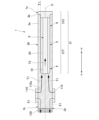
- FIG. 1 is a cross-sectional view of a heat pipe according to a first embodiment.
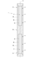
- FIG. 6 is a cross-sectional view of a heat pipe according to a second embodiment.
- 10A and 10B are cross-sectional views of heat pipes according to modified examples of the first and second embodiments.
- the heat pipe 1 includes a wick 20 and a container 30.
- the container 30 has an elongated shape extending in one direction.
- the wick 20 is housed in the container 30.
- a working fluid (not shown) is sealed in the container 30.
- the container 30 has a storage portion 31 that stores the wick 20 and the working fluid, and an electrical connection portion 32 that is arranged at a position different from the storage portion 31.
- the electrical connection portion 32 functions as a terminal that electrically connects the first member 110 and the second member 120
- the accommodating portion 31 functions as a heat transport element that transports heat from the electrical connection portion 32 by utilizing the latent heat of the working fluid sealed in the container 30.
- FIG. 1 for the sake of explanation, only a portion of the first member 110 and the second member 120 is shown.
- the end where the accommodation portion 31 is provided is referred to as a first end 1a
- the end where the electrical connection portion 32 is provided, opposite to the first end is referred to as a second end 1b.
- the direction in which the container 30 extends is simply referred to as the longitudinal direction X.
- the direction from the second end 1b to the first end 1a is referred to as the +X direction
- the direction from the first end 1a to the second end 1b is referred to as the -X direction.
- the direction perpendicular to the central axis O is referred to as the radial direction
- the direction going around the central axis O is referred to as the circumferential direction.
- the container 30 has a cylindrical shape.
- the container 30 includes a container body 3a and a sealing portion 3b.
- the container body 3a has an inner hole 10 extending from the first end 1a toward the -X direction.
- the inner hole 10 is formed in the storage portion 31, and is not formed in the electrical connection portion 32.
- the end of the inner hole 10 on the +X direction side is air-tightly sealed by the sealing portion 3b.
- a sealing member such as an O-ring may be disposed between the container body 3a and the sealing portion 3b.
- the method of sealing the first end 1a of the heat pipe 1 is not limited to using the sealing portion 3b.
- the end of the container body 3a on the +X direction side may be deformed to airtightly seal the inner hole 10.
- the container 30 does not need to have the sealing portion 3b.
- the outer diameter of the container 30 and the diameter of the inner bore 10 are approximately constant.
- the material of the container 30 can be appropriately selected depending on conditions such as the type of working fluid and the operating temperature.
- the container 30 is formed of a metal such as copper, steel, or aluminum.
- a metal material with high thermal conductivity and electrical conductivity such as copper or aluminum is used, it is possible to improve the heat transport and thermal diffusivity in the storage section 31 and to suitably conduct electricity in the electrical connection section 32.
- copper is used as the material of the container 30.
- the electrical connection portion 32 has a cylindrical shape extending in the longitudinal direction X and is solid. That is, in a cross section perpendicular to the longitudinal direction X, the entire surface of the electrical connection portion 32 is made of the metal forming the container 30.
- the length of the electrical connection portion 32 in the longitudinal direction X is, for example, 5 mm or more.
- the ratio of the length of the electrical connection portion 32 in the longitudinal direction X to the total length of the heat pipe 1 in the longitudinal direction X may be 25 to 50%.
- the length of the electrical connection portion 32 in the longitudinal direction X is a length that allows the first member 110 and the second member 120 to be electrically connected to each other.
- the storage portion 31 has a cylindrical shape with both ends sealed in the longitudinal direction X.
- the storage portion 31 is not separate from the electrical connection portion 32, and in the container 30, the storage portion 31 and the electrical connection portion 32 are integrally formed.
- the radial thickness L of the container 30 in the storage section 31 (hereinafter referred to as the wall thickness of the container 30) is, for example, 0.2 mm or more.
- a working fluid is sealed in the inner hole 10 of the housing 31.
- the working fluid is a known heat transport medium capable of undergoing a phase change, and changes between liquid and gas phases within the inner hole 10.
- working fluids examples include water, alcohol, ammonia, and alternative freon.
- the type of working fluid may be changed as appropriate depending on the temperature range of heat transported by the heat pipe 1 and the amount of heat transported.
- a working fluid in the liquid phase may be referred to as a "working liquid” and a working fluid in the gas phase may be referred to as "steam".
- the term "working fluid" will be used.
- a wick 20 is disposed within the inner hole 10. In the longitudinal direction X, the wick 20 extends over the entire length of the inner hole 10.
- the wick 20 is formed in an annular shape along the inner circumferential surface of the storage section 31.
- An internal space S is formed radially inside the wick 20. Note that the wick 20 does not have to be formed in some areas of the inner circumferential surface of the storage section 31.
- the wick 20 has many pores that can generate capillary forces in the liquid-phase working fluid. These pores are used as liquid flow paths to allow the working fluid to flow, and serve as return paths (hereinafter referred to as "flow paths") for returning the working fluid from the condensation section 6 to the evaporation section 4, which will be described later.
- the working fluid in the flow paths flows in the longitudinal direction X and the circumferential direction due to capillary forces.
- the wick 20 is formed, for example, by bundling a plurality of thin metal wires, for example, thin copper wires.
- the thin copper wires are linear bodies extending in the longitudinal direction X of the container 30.
- the outer diameter of the thin copper wires is, for example, several ⁇ m to several hundred ⁇ m.
- Pores extending in the longitudinal direction X are formed between the thin copper wires. These pores are used as the liquid flow paths described above.
- the working fluid also flows in the circumferential direction of the heat pipe 1 as the working fluid moves between the pores extending in the longitudinal direction X.
- the wick 20 is not limited to thin metal wires, but may be a metal mesh (reticulated body), a sintered body of metal powder, or a mixture of these.
- Metals that make up the wick 20 include copper, aluminum, stainless steel, and alloys of these.
- the wick 20 is not limited to being made of metal, and may be made of carbon materials, etc.
- the wick 20 may be made of fine carbon wires, carbon mesh, etc.
- the accommodation section 31 has a heat transporting section 31T and a cooling section 31C provided on the +X direction side of the heat transporting section 31T.
- the heat transporting section 31T transfers heat generated in the electrical connection section 32 toward the cooling section 31C.
- the cooling section 31C releases the heat transported by the heat transporting section 31T to the outside of the heat pipe 1.
- a heat dissipation structure (not shown) may be disposed radially outside the cooling section 31C.
- the heat dissipation structure is, for example, a heat sink.
- the heat transporting part 31T has an evaporation part 4 where the working fluid evaporates to generate steam, and an intermediate part 5 that moves the steam generated in the evaporation part 4 toward the cooling part 31C.
- the cooling part 31C has a condensation part 6 where the steam generated in the evaporation part 4 is condensed to generate working fluid.
- the evaporation part 4, the intermediate part 5, and the condensation part 6 are arranged in this order toward the +X direction.
- the electrical connection portion 32 is a rod whose entire surface in a cross section perpendicular to the longitudinal direction X is made of metal, has high electrical conductivity, and electrically connects the first member 110 and the second member 120.
- the first member 110 is, for example, a bus bar.
- the second member 120 is a device that generates or receives a current, such as a battery or an electronic component.
- the electrical connection portion 32 passes through the hole 110a of the first member 110, and the outer peripheral surface of the electrical connection portion 32 is in contact with the inner surface of the hole 110a of the first member 110.
- the end face of the electrical connection portion 32 on the -X direction side is in contact with the second member 120.
- a hole having a circular opening may be formed in the second member 120, and the cylindrical electrical connection portion 32 may be inserted into the hole.
- the electrical connection portion 32 is electrically connected to the two members 110, 120 and serves as a terminal that passes a current flowing between the two members 110, 120.
- the first member 110 and the electrical connection portion 32, and the second member 120 and the electrical connection portion 32 may be electrically connected by soldering, respectively.
- the heat generated at the connection surface between the first member 110 and the electrical connection portion 32 moves within the electrical connection portion 32 in the direction of the arrow T1 shown in Figure 1, moves in the direction of the arrow T2 by the working fluid sealed in the storage portion 31, and is further transported toward the outside of the heat pipe 1 in the cooling portion 31C. More specifically, heat is conducted from the connection surface between the first member 110 and the electrical connection portion 32 toward the accommodation portion 31.
- the heat conducted to the accommodation portion 31 heats the working fluid permeating into the flow path of the wick 20 of the evaporation portion 4, causing it to evaporate and become steam.
- the steam generated in the evaporator 4 flows through the internal space S toward the condenser 6, which has a lower pressure and temperature than the evaporator 4.
- the container 30 is cooled by the heat dissipation structure, so that a portion of the steam condenses to become working fluid.
- the working fluid generated in the condenser 6 permeates into the flow path of the wick 20.
- the working fluid liquefied in the condensation section 6 flows through the flow path of the wick 20 and is returned from the condensation section 6 to the evaporation section 4 via the intermediate section 5. In this way, the working fluid circulates within the housing 31 including the wick 20 , thereby transporting heat from the electrical connection portion 32 to the first end 1 a of the heat pipe 1 .
- the entire surface of the electrical connection portion 32 is made of metal, whereas the wall thickness L of the container 30 in the storage portion 31 is very small, for example, about 0.2 mm.
- Such a difference in the metal thickness of the container 30 causes a large electrical resistance, making it difficult for a current to flow in the direction from the electrical connection portion 32 toward the storage portion 31.
- a working fluid that transports heat and a wick 20 are provided inside the accommodation portion 31, and the thermal resistance between the accommodation portion 31 and the electrical connection portion 32 is small. Therefore, heat is smoothly transferred from the electrical connection portion 32 to the accommodation portion 31.
- the heat pipe 1 of this embodiment comprises a container 30 in which a working fluid is sealed, and a wick 20 housed in the container 30, and the container 30 has an accommodation section 31 that houses the wick 20 and the working fluid, and an electrical connection section 32 arranged at a position different from the accommodation section 31 in the longitudinal direction X.
- the heat pipe 1 can function as a terminal that electrically connects the first member 110 and the second member 120, and can also function as a heat transport element that transports heat from the electrical connection portion 32.
- the working fluid sealed inside the accommodation portion 31 that contacts the electrical connection portion 32 circulates, thereby efficiently transporting heat from the electrical connection portion 32 to the first end 1a of the heat pipe 1.
- the electrical connection portion 32 and the accommodating portion 31 are integrally provided in the container 30, so that the electrical connection portion 32 can be cooled in a smaller space.
- the length of the electrical connection portion 32 in the longitudinal direction X is 5 mm or more.
- the thickness of the container at the end face in the longitudinal direction of the heat pipe is preferably thin to reduce thermal resistance and improve thermal conduction, and is set to 5 mm or less. Therefore, in the conventional technology, it was difficult to make the end face of the heat pipe formed so thin function as an electrical connection part. In contrast, in this embodiment, by ensuring the length of the electrical connection part 32 in the heat pipe 1, it is possible to reliably electrically connect the first member 110 and the second member 120.
- FIG. 2 shows a heat pipe 1 according to a second embodiment. This embodiment differs from the heat pipe 1 of the first embodiment in that the diameter of the inner hole 10 of the container 30 is not constant in the longitudinal direction.
- the inner surface of the accommodating portion 31 is tapered, and the inner diameter of the inner hole 10 gradually decreases from the first end 1a toward the -X direction. Therefore, the wall thickness L of the container 30 in the accommodating portion 31 decreases as it moves away from the electrical connection portion 32.
- the thickness of the wick 20 gradually decreases from the first end 1a toward the -X direction. This makes it possible to more reliably secure the internal space S, which is the space through which the vapor moves, in the evaporation section 4 and the intermediate section 5.
- the cross-sectional area of the internal space S of the wick 20 in a cross section perpendicular to the longitudinal direction X increases with increasing distance from the electrical connection portion 32.
- the internal space S of the wick 20 in a cross section has a circular shape. Therefore, the diameter of the internal space S in the cross section increases with increasing distance from the electrical connection portion 32. This allows the steam to move more smoothly to the condensation portion 6.
- the heat pipe 1 has one accommodating portion 31 and one electrical connection portion 32, but the heat pipe 1 may have one or more accommodating portions 31 and one or more electrical connection portions 32.
- the heat pipe 1 includes one electrical connection portion 32 and two housing portions 31 sandwiching the electrical connection portion 32. This allows the heat generated at the electrical connection portion 32 to be efficiently transferred to both ends of the heat pipe 1 in the longitudinal direction by the two housing portions 31.
- the container 30 is not limited to a cylindrical shape, and may be a rectangular or polygonal prism shape.
- the container 30 may be a shape that combines a cylindrical, rectangular or polygonal prism shape in the longitudinal direction.
- the shape of the container 30 may be appropriately changed according to the shapes of the first member 110, the second member 120, and the heat dissipation structure that are connected to the heat pipe 1.
- the electrical connection portion 32 may have a square prism shape that fits into the recess.
- the electrical connection portion 32 may have a square prism shape and the accommodation portion 31 may have a circular shape.
- the length of the longitudinal direction X of the electrical connection part 32 is not limited to 5 mm or more.
- the length of the longitudinal direction X of the electrical connection part 32 may be any length that allows the desired current to flow appropriately when the two members 110, 120 are electrically connected.
- the length of the longitudinal direction X of the electrical connection part 32 may be 1 mm or less, or may be in the range of 1 to 5 mm. If the second member 120 is a large battery, the length of the longitudinal direction X of the electrical connection part 32 may be in the range of 5 to 20 mm in order to allow a high current to flow appropriately.
- the length of the electrical connection portion 32 in the longitudinal direction X may be a length that allows the electrical connection portion 32 to be stably fixed in a hole provided in the second member 120. In this case, it becomes possible to use the heat pipe 1 as a pin-type terminal to be inserted into the hole of the second member 120. Furthermore, the outer diameter of the electrical connection portion 32 may be a dimension that allows a desired current to flow appropriately when the two members 110, 120 are electrically connected.
Landscapes
- Engineering & Computer Science (AREA)
- Microelectronics & Electronic Packaging (AREA)
- Physics & Mathematics (AREA)
- Thermal Sciences (AREA)
- Life Sciences & Earth Sciences (AREA)
- Sustainable Development (AREA)
- Mechanical Engineering (AREA)
- General Engineering & Computer Science (AREA)
- Cooling Or The Like Of Semiconductors Or Solid State Devices (AREA)
Priority Applications (2)
| Application Number | Priority Date | Filing Date | Title |
|---|---|---|---|
| DE112024001595.6T DE112024001595T5 (de) | 2023-04-05 | 2024-04-04 | Wärmerohr |
| JP2025513178A JPWO2024210182A1 (https=) | 2023-04-05 | 2024-04-04 |
Applications Claiming Priority (2)
| Application Number | Priority Date | Filing Date | Title |
|---|---|---|---|
| JP2023-061165 | 2023-04-05 | ||
| JP2023061165 | 2023-04-05 |
Publications (1)
| Publication Number | Publication Date |
|---|---|
| WO2024210182A1 true WO2024210182A1 (ja) | 2024-10-10 |
Family
ID=92971955
Family Applications (1)
| Application Number | Title | Priority Date | Filing Date |
|---|---|---|---|
| PCT/JP2024/013978 Ceased WO2024210182A1 (ja) | 2023-04-05 | 2024-04-04 | ヒートパイプ |
Country Status (3)
| Country | Link |
|---|---|
| JP (1) | JPWO2024210182A1 (https=) |
| DE (1) | DE112024001595T5 (https=) |
| WO (1) | WO2024210182A1 (https=) |
Cited By (1)
| Publication number | Priority date | Publication date | Assignee | Title |
|---|---|---|---|---|
| US20240240874A1 (en) * | 2023-01-18 | 2024-07-18 | Cisco Technology, Inc. | Multiple wick section heatpipe for effective heat transfer |
Citations (6)
| Publication number | Priority date | Publication date | Assignee | Title |
|---|---|---|---|---|
| JPS51103353U (https=) * | 1975-02-17 | 1976-08-19 | ||
| JPH10285751A (ja) * | 1997-04-10 | 1998-10-23 | Furukawa Electric Co Ltd:The | 電気接続箱 |
| US20130192798A1 (en) * | 2012-01-26 | 2013-08-01 | Lear Corporation | Cooled electric assembly |
| WO2013139666A1 (en) * | 2012-03-22 | 2013-09-26 | Abb Technology Ag | Cooling apparatus for switchgear with heat pipe structure having integrated busbar tube |
| EP2983261A1 (en) * | 2014-08-04 | 2016-02-10 | ABB Technology AG | Bus bar with integrated heat pipe |
| US20180166757A1 (en) * | 2016-12-13 | 2018-06-14 | ThermAvant Technologies, LLC | Thermal management of energy storage devices via oscillating heat pipes |
-
2024
- 2024-04-04 JP JP2025513178A patent/JPWO2024210182A1/ja active Pending
- 2024-04-04 WO PCT/JP2024/013978 patent/WO2024210182A1/ja not_active Ceased
- 2024-04-04 DE DE112024001595.6T patent/DE112024001595T5/de active Pending
Patent Citations (6)
| Publication number | Priority date | Publication date | Assignee | Title |
|---|---|---|---|---|
| JPS51103353U (https=) * | 1975-02-17 | 1976-08-19 | ||
| JPH10285751A (ja) * | 1997-04-10 | 1998-10-23 | Furukawa Electric Co Ltd:The | 電気接続箱 |
| US20130192798A1 (en) * | 2012-01-26 | 2013-08-01 | Lear Corporation | Cooled electric assembly |
| WO2013139666A1 (en) * | 2012-03-22 | 2013-09-26 | Abb Technology Ag | Cooling apparatus for switchgear with heat pipe structure having integrated busbar tube |
| EP2983261A1 (en) * | 2014-08-04 | 2016-02-10 | ABB Technology AG | Bus bar with integrated heat pipe |
| US20180166757A1 (en) * | 2016-12-13 | 2018-06-14 | ThermAvant Technologies, LLC | Thermal management of energy storage devices via oscillating heat pipes |
Cited By (1)
| Publication number | Priority date | Publication date | Assignee | Title |
|---|---|---|---|---|
| US20240240874A1 (en) * | 2023-01-18 | 2024-07-18 | Cisco Technology, Inc. | Multiple wick section heatpipe for effective heat transfer |
Also Published As
| Publication number | Publication date |
|---|---|
| JPWO2024210182A1 (https=) | 2024-10-10 |
| DE112024001595T5 (de) | 2026-01-29 |
Similar Documents
| Publication | Publication Date | Title |
|---|---|---|
| US6293333B1 (en) | Micro channel heat pipe having wire cloth wick and method of fabrication | |
| US20060207750A1 (en) | Heat pipe with composite capillary wick structure | |
| US20070246194A1 (en) | Heat pipe with composite capillary wick structure | |
| US20130160974A1 (en) | Loop heat pipe and electronic apparatus | |
| US20090166004A1 (en) | Heat pipe | |
| JP2000146471A (ja) | ループ型ヒートパイプ | |
| JP2005518518A (ja) | 毛管蒸発器 | |
| WO2011007604A1 (ja) | ループ型ヒートパイプ及びその起動方法 | |
| JP6827362B2 (ja) | ヒートパイプ | |
| US20070240852A1 (en) | Heat pipe with heat reservoirs at both evaporating and condensing sections thereof | |
| CA2632725C (en) | Evaporator for use in a heat transfer system | |
| US20250052513A1 (en) | Heat pipe | |
| WO2024210182A1 (ja) | ヒートパイプ | |
| CN209605636U (zh) | 热管及具有该热管的散热器 | |
| US12058841B2 (en) | Cooling device and cooling system using cooling device | |
| JP2017072340A (ja) | ヒートパイプ | |
| JP2009115346A (ja) | ヒートパイプ | |
| JP2010025407A (ja) | ヒートパイプコンテナ及びヒートパイプ | |
| JP6875463B2 (ja) | モータ | |
| JP2004218887A (ja) | 電子素子の冷却装置 | |
| JP2018123987A (ja) | ベーパーチャンバ | |
| US20220260317A1 (en) | Cooling device | |
| JP2007263427A (ja) | ループ型ヒートパイプ | |
| TWI821783B (zh) | 熱導板及散熱器 | |
| JP7517672B2 (ja) | 装置、熱交換器、および蒸発器 |
Legal Events
| Date | Code | Title | Description |
|---|---|---|---|
| 121 | Ep: the epo has been informed by wipo that ep was designated in this application |
Ref document number: 24784964 Country of ref document: EP Kind code of ref document: A1 |
|
| WWE | Wipo information: entry into national phase |
Ref document number: 2501006696 Country of ref document: TH |
|
| ENP | Entry into the national phase |
Ref document number: 2025513178 Country of ref document: JP Kind code of ref document: A |
|
| WWE | Wipo information: entry into national phase |
Ref document number: 2025513178 Country of ref document: JP |
|
| WWE | Wipo information: entry into national phase |
Ref document number: 112024001595 Country of ref document: DE |
|
| WWP | Wipo information: published in national office |
Ref document number: 112024001595 Country of ref document: DE |
|
| 122 | Ep: pct application non-entry in european phase |
Ref document number: 24784964 Country of ref document: EP Kind code of ref document: A1 |