WO2024210104A1 - イオン発生装置、イオンビーム照射装置およびイオン取り出し方法 - Google Patents
イオン発生装置、イオンビーム照射装置およびイオン取り出し方法 Download PDFInfo
- Publication number
- WO2024210104A1 WO2024210104A1 PCT/JP2024/013504 JP2024013504W WO2024210104A1 WO 2024210104 A1 WO2024210104 A1 WO 2024210104A1 JP 2024013504 W JP2024013504 W JP 2024013504W WO 2024210104 A1 WO2024210104 A1 WO 2024210104A1
- Authority
- WO
- WIPO (PCT)
- Prior art keywords
- voltage value
- voltage
- ion
- auxiliary
- chamber
- Prior art date
- Legal status (The legal status is an assumption and is not a legal conclusion. Google has not performed a legal analysis and makes no representation as to the accuracy of the status listed.)
- Ceased
Links
Images





Classifications
-
- H—ELECTRICITY
- H01—ELECTRIC ELEMENTS
- H01J—ELECTRIC DISCHARGE TUBES OR DISCHARGE LAMPS
- H01J27/00—Ion beam tubes
- H01J27/02—Ion sources; Ion guns
- H01J27/16—Ion sources; Ion guns using high-frequency excitation, e.g. microwave excitation
- H01J27/18—Ion sources; Ion guns using high-frequency excitation, e.g. microwave excitation with an applied axial magnetic field
-
- H—ELECTRICITY
- H01—ELECTRIC ELEMENTS
- H01J—ELECTRIC DISCHARGE TUBES OR DISCHARGE LAMPS
- H01J37/00—Discharge tubes with provision for introducing objects or material to be exposed to the discharge, e.g. for the purpose of examination or processing thereof
- H01J37/02—Details
- H01J37/04—Arrangements of electrodes and associated parts for generating or controlling the discharge, e.g. electron-optical arrangement or ion-optical arrangement
- H01J37/08—Ion sources; Ion guns
Definitions
- This invention relates to, for example, an ion generating device, an ion beam irradiation device, and an ion extraction method for generating and extracting ions.
- Ion sources have been provided for use in particle beam therapy devices that irradiate an affected area (irradiation target) such as cancer cells with charged particles (ion beams) to treat the affected area.
- an ion source is the electron cyclotron resonance (ECR) ion source (see Patent Document 1).
- the present invention aims to provide an ion generating device, an ion beam irradiation device, and an ion extraction method that can increase the amount of ions produced.
- the present invention is characterized in that it is an ion generating device and an ion extraction method, comprising: a chamber for generating an ion beam from a gas introduced into a vacuum; a gas supply unit for supplying gas into the chamber; an ionization energy supply unit for supplying ionization energy for ionizing atoms of the gas into the chamber; an auxiliary electrode disposed in the chamber; a voltage application unit for applying a negative auxiliary voltage to the auxiliary electrode; and a voltage control unit for controlling the voltage value of the auxiliary voltage applied from the voltage application unit to the auxiliary electrode, the voltage control unit being configured to change the voltage value of the auxiliary voltage over time as a two-level pulse wave between a first voltage value that is a predetermined voltage value and a second voltage value that is lower than the first voltage value.
- This invention provides an ion generating device, an ion beam irradiation device, and an ion extraction method that can increase the amount of ions produced.
- FIG. 1 is a diagram showing a configuration of an ion generating device according to the present invention.
- FIG. 2 is a diagram showing an example of the configuration of an auxiliary voltage application unit of the present invention.
- 4 is a time chart illustrating a method for controlling an auxiliary voltage value.
- FIG. 4 is an explanatory diagram showing a change in ion current value in an embodiment of the present invention.
- FIG. 11 is an explanatory diagram showing changes in ion current value in another embodiment of the present invention and a comparative example.
- FIG. 4 is an explanatory diagram showing changes in ion current value in a plurality of examples of the present invention and a comparative example.
- FIG. 4 is an explanatory diagram showing the relationship between the auxiliary voltage value and the ion current value in a plurality of examples of the present invention and a comparative example.
- FIG. 1 is a diagram showing a configuration of an ion irradiation apparatus according to the present invention.
- 6 is a time chart illustrating a modified example of the auxiliary voltage value control method.
- FIG. 1 is a diagram showing the configuration of an ion generator 1 of the present invention.
- the ion generator 1 is a device that causes a plasma discharge on a gas introduced into a vacuum, ionizing the gas by removing electrons from the atoms of the introduced gas, and generating an ion beam that is emitted in a predetermined direction.
- the ion generator 1 can also be said to be a device for extracting ions as an ion beam.
- the ion generator 1 of this embodiment has an ECR ion source (ECR ion generator) 10 that ionizes gas atoms using the ECR discharge method.
- ECR ion source 10 uses the principle of applying microwaves to a gas introduced into a vacuum, ionizing the electrons that trigger plasma discharge, and then confining the ionized electrons in a magnetic field, which repeatedly resonates with the microwaves to ionize the gas atoms.
- the ECR ion source 10 includes a plasma chamber 11 formed of a vacuum material.
- the plasma chamber 11 is generally cylindrical, with a vacuum opening (first opening) 11a at one end (left end in the figure), and an ion ejection opening (second opening) 11b at the other end (right end in the figure) for ejecting ions generated inside the plasma chamber 11 into the space outside the plasma chamber 11.
- ions are ejected as an ion beam from the ion ejection opening 11b. Therefore, the vacuum opening 11a is located upstream (rear) from the direction of travel of the ion beam, and the ion ejection opening 11b is located downstream from the direction of travel of the ion beam.
- a gas nozzle 12 for introducing gas into the interior of the plasma chamber 11 (the center of the internal space of the plasma chamber 11) and a microwave waveguide 13 (ionization energy supply unit) connected to a microwave power source 13a and transmitting microwaves into the plasma chamber 11 are inserted.
- the gas nozzle 12 is connected to a gas supply unit 12a that supplies gas to the ECR ion source 10.
- the gas supply unit 12a has a plurality of gas supply systems that supply one or a plurality of types of gas to the ECR ion source 10.
- the gas supply unit 12a has gas supply systems such as an oxygen (O 2 ) gas supply system, a methane (CH 4 ) gas supply system, and a helium (He) gas supply system.
- the vacuum opening 11a is completely covered from the outside by a vacuum flange 14a, which is connected to a vacuum pump 14 via a vacuum pipe.
- a vacuum flange 14a which is connected to a vacuum pump 14 via a vacuum pipe.
- An extraction electrode section 15 is provided on the ion emission opening 11b side of the plasma chamber 11 (the tip side in the emission direction of the ion beam) to attract ions generated inside the plasma chamber 11 and extract them to the outside through the ion emission opening 11b.
- the extraction electrode section 15 is formed in a generally cylindrical shape as a whole.
- the extraction electrode section 15 forms a cylindrical extraction space that extends along the emission direction of the ion beam.
- the extraction electrode section 15 has a lower voltage (e.g., GND potential (0V)) than the plasma chamber 11 and the components attached thereto (such as the multi-pole magnet 16, axial magnetic field magnet 17, and anode 18 described below).
- the extraction electrode section 15 and the extraction space formed thereby are arranged to extend from the inside of the plasma chamber 11 through the ion emission opening 11b to the outside of the plasma chamber 11. That is, the rear end of the extraction electrode section 15 is located inside the plasma chamber 11, and the front end of the extraction electrode section 15 is located outside the plasma chamber 11. Ions generated inside the plasma chamber 11 are guided to the outside of the plasma chamber 11 through the extraction electrode section 15 and the extraction space formed thereby.
- the ECR ion source 10 is also provided with a multi-pole magnet 16 and an axial magnetic field magnet 17, which are provided outside the extraction electrode 15 (outside the plasma chamber 11), i.e., surrounding the outer periphery in the emission direction of the ion beam 1b.
- the multi-pole magnet 16 and the axial magnetic field magnet 17 in this embodiment are cylindrical overall, and are provided outside the plasma chamber 11 (along the outer periphery of the plasma chamber 11).
- a six-pole magnet (Hexapole) can be used as the multi-pole magnet 16.
- a ring magnet or a solenoid electromagnet can be used as the axial magnetic field magnet 17.
- An anode 18 is also provided inside the plasma chamber 11.
- the anode 18 is provided downstream in the plasma chamber 11 when viewed from the direction of emission of the ion beam, and is disposed a predetermined distance in the emission direction from the rear end of the extraction electrode section 15.
- the anode 18 is formed in a disk shape, and has a through hole within the circular surface.
- the through hole of the anode 18 is disposed approximately coaxially with the central axis of the plasma chamber 11, and the inner diameter of the through hole of the anode 18 is set to be larger than the outer diameter of the ion beam 1b emitted from the plasma chamber 11.
- an auxiliary electrode 19 is inserted into the vacuum opening 11a and is connected to an auxiliary voltage application unit 20 including an auxiliary voltage power supply and is disposed within the plasma chamber 11. That is, the auxiliary electrode 19 is disposed on the upstream side (opposite the ion emission opening 11b) within the plasma chamber 11.
- a bias disk for example, can be used as the auxiliary electrode 19.
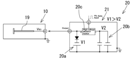
- FIG. 2 is a diagram showing an example of the configuration of the auxiliary voltage application unit 20 of the present invention.
- the auxiliary voltage application unit 20 is configured to be able to change the voltage value (hereinafter referred to as the "auxiliary voltage value”) VBD of the negative voltage (hereinafter referred to as the "auxiliary voltage”) applied to the auxiliary electrode 19 over time (to generate a pulse voltage).
- the auxiliary voltage application unit 20 may be configured as an electric circuit 21 having a first voltage generation unit 20a for generating a steady voltage, a second voltage generation unit 20b for generating a voltage different from the steady voltage, and a switch unit 20c for switching ON/OFF of the second voltage generation unit 20b.
- the auxiliary voltage application unit 20 is not particularly limited as long as it is configured to be able to change the voltage value of the auxiliary voltage over time.
- a high-voltage amplifier capable of changing the voltage value of the auxiliary voltage over time may be adopted.
- the ion generator 1 is connected to a control device 30 for controlling each component of the ion generator 1 (ECR ion source 10).
- the control device 30 includes a calculation unit and a memory unit, etc., and executes various calculations and control operations in the ion generator 1 (ECR ion source 10).
- the calculation unit is an arithmetic processing unit including a CPU or MPU, etc.
- the memory unit includes a RAM (DRAM) and ROM, etc., and stores various programs for executing various calculations and control operations in the ion generator 1 and default values for various information.
- a series of operations in the ion generator 1 (ECR ion source 10) is realized by the control of each component of the ion generator 1 (ECR ion source 10) by the control device 30.
- the control device 30 operates according to appropriate programs stored in the memory unit, thereby functioning as a gas control unit 31, a microwave control unit 32, a vacuum pump control unit 33, an extraction voltage control unit 34, a magnet current control unit 35, and an auxiliary voltage control unit 36.
- the gas control unit 31 controls the operation of the gas valve provided in the gas supply unit 12a, switching the gas valve between open and closed states, and controlling the flow rate of gas passing through the gas valve (supplied into the plasma chamber 11).
- the microwave control unit 32 controls the operation of the microwave power supply 13a of the ECR ion source 10 to adjust the microwave power (input power for the accelerating electric field) input into the plasma chamber 11 through the microwave waveguide 13.
- the microwave power input power for the accelerating electric field
- the plasma 1a generated in the plasma chamber 11 can be made to have an appropriate density.
- the vacuum pump control unit 33 controls the operation of the vacuum pump 14, such as turning the vacuum pump 14 on and off and setting the exhaust volume. By appropriately controlling the operation of the vacuum pump 14, the inside of the plasma chamber 11 is maintained in a high vacuum state.
- the extraction voltage control unit 34 sets the voltage value of the extraction voltage applied to the extraction electrode unit 15 from a specified power supply in order to extract the desired ions with a specified energy from the plasma 1a generated in the plasma chamber 11 in the ECR ion source 10.
- the magnet current control unit 35 selects the frequency of the electrons moving circularly around the magnetic field generated by the multi-pole magnet 16 and the axial magnetic field magnet 17 in the ECR ion source 10 to a value close to the frequency of the microwaves applied through the microwave waveguide 13, and sets the voltage value applied from a specified power source to the multi-pole magnet 16 and the axial magnetic field magnet 17 (the current value flowing through the multi-pole magnet 16 and the axial magnetic field magnet 17, determined by the voltage value: the electromagnet current value for the confinement magnetic field) so that plasma 1a is easily generated in the plasma chamber 11 by the electron cyclotron resonance (ECR) phenomenon.
- ECR electron cyclotron resonance
- the auxiliary voltage control unit 36 controls the operation of the auxiliary voltage application unit 20 of the ECR ion source 10 to adjust the auxiliary voltage value. Specifically, the auxiliary voltage control unit 36 controls the operation of the auxiliary voltage application unit 20 to change the auxiliary voltage value over time.
- gas is introduced from the gas nozzle 12 into the plasma chamber 11, in which a vacuum is maintained by the vacuum pump 14.
- Microwave power from a microwave power source (not shown) is applied from the microwave waveguide 13 to the gas introduced into the plasma chamber 11, ionizing the electrons that trigger the plasma discharge.
- the ionized electrons are then trapped by the magnetic fields of the multi-pole magnet 16 and axial magnetic field magnet 17 that surround the side of the plasma chamber 11, and are repeatedly resonated with the microwaves to generate plasma 1a, thereby ionizing the gas atoms.
- the ions (ion groups) generated in the plasma chamber 11 are extracted from the plasma chamber 11 through the extraction electrode section 15 by the electric field generated between the anode 18 and the extraction electrode section 15, which is placed at a low voltage, and are emitted in a predetermined direction (emission direction) as an ion beam 1b by being given a predetermined energy.
- the ion beam 1b emitted from the extraction electrode section 15 is introduced into a beam transport system (ion beam transport means) connected to the extraction electrode section 15. Therefore, the ion beam 1b extracted from the plasma chamber 11 is irradiated onto the irradiation target via the ion beam transport means.
- a negative auxiliary voltage is applied to the auxiliary electrode 19 when microwave power is applied from the microwave waveguide 13 to the gas introduced into the plasma chamber 11. This makes it possible to push back electrons flowing out (dissipating) from the plasma 1a to the plasma 1a, thereby increasing the intensity of the ion beam 1b. That is, by applying a negative auxiliary voltage to the auxiliary electrode 19, the amount of ions generated can be increased.
- the amount of ions generated in the plasma chamber 11 (extracted from the extraction electrode 15) can be further increased.
- FIG. 3 is a time chart for explaining the auxiliary voltage value control method of the present invention. Note that the change in the auxiliary voltage value VBD described below is due to the operation of the auxiliary voltage application unit 20 and the auxiliary voltage control unit 36 that controls the operation of the auxiliary voltage application unit 20.
- the time chart shown in FIG. 3 is intended to show the timing relationship of each operation, and the width of the time shown is not proportional to the actual time.
- the auxiliary voltage value VBD changes over time as a two-level pulse wave having a first voltage value V1, which is a predetermined voltage value, and a second voltage value V2, which is lower than the first voltage value V1.
- the second voltage value V2 has a larger absolute value than the first voltage value V1.
- the first voltage value V1 is a default value (initial setting value) of the auxiliary voltage value VBD .
- the first voltage value V1 is at least less than 0 V, and can be less than ⁇ 100 V, preferably less than ⁇ 150 V, and more preferably less than ⁇ 160 V.
- the second voltage value V2 is a voltage value that is at least lower than the first voltage value V1, and can be, for example, a voltage value that is 1.2 times or more the first voltage value V1. A detailed method for setting the second voltage value V2 will be described later.
- the auxiliary voltage value VBD changes over time as a two-level rectangular wave of a first voltage value V1 and a second voltage value V2.
- the timing when the auxiliary voltage value VBD changes from the first voltage value V1 to the second voltage value V2 (the voltage value decreases) is the auxiliary voltage decrease timing (first timing) T1
- the timing when the auxiliary voltage value VBD changes from the second voltage value V2 to the first voltage value V1 (the voltage value increases) is the auxiliary voltage increase timing (second timing) T2
- the period from the auxiliary voltage decrease timing T1 to the auxiliary voltage increase timing T2 is the high voltage period (first period) Th.
- the high voltage period Th can also be called the pulse width in the waveform of the auxiliary voltage value VBD .
- the timing when the supply of ionizing energy from the microwave waveguide 13 (output of microwave power) starts is defined as ionizing energy supply start timing (third timing) T3
- the timing when the supply of ionizing energy from the microwave waveguide 13 (output of microwave power) ends is defined as ionizing energy supply end timing (fourth timing) T4
- the period from the ionizing energy supply start timing T3 to the ionizing energy supply end timing T4 (microwave power output period) is defined as the ionizing energy supply period Tp.
- the auxiliary voltage reduction timing T1 is set within the ionization energy supply period Tp. That is, the auxiliary voltage reduction timing T1 is set after the ionization energy supply start timing T3 and before the ionization energy supply end timing T4. Therefore, because the auxiliary voltage reduction timing T1 is set within the ionization energy supply period Tp, there is at least a period of overlap between the high voltage period Th and the ionization energy supply period Tp. That is, in the present invention, a pulse voltage is applied while the microwaves are ON.
- the auxiliary voltage rise timing T2 is set within the ionization energy supply period Tp.
- the auxiliary voltage rise timing T2 is set after the ionization energy supply start timing T3 and before the ionization energy supply end timing T4. Therefore, because the auxiliary voltage rise timing T2 is set within the ionization energy supply period Tp, there is at least a period of overlap between the high voltage period Th and the ionization energy supply period Tp.
- the high voltage period Th is set within the ionization energy supply period Tp. In other words, the entire period of the high voltage period Th overlaps with the ionization energy supply period Tp.
- the auxiliary voltage reduction timing T1 is set after a predetermined time (predetermined period) Tg has elapsed from the ionization energy supply start timing T3.
- the predetermined time Tg is set according to the time required to increase the amount of ions (particularly multiply charged ions) generated.
- the average time ⁇ can be calculated from the following [Equation 1] and [Equation 2] using the electron density n e , the electron velocity v e , and the ionization cross section ⁇ z-1 ⁇ z (v e ) from the z-1 valence to the z valence.
- the predetermined time Tg can be set to a length equal to or greater than 60% of the average time ⁇ , preferably equal to or greater than 80% of the average time ⁇ , more preferably equal to or greater than 90% of the average time ⁇ , and preferably equal to or greater than 100% of the average time ⁇ .
- the predetermined time Tg can be set to a length equal to or greater than 100% of the average time ⁇ . That is, it is preferable to set the auxiliary voltage reduction timing T1 after the lapse of a time equal to or greater than the average time ⁇ from the ionization energy supply start timing T3. ⁇ Ion current value when the present invention is adopted>
- the ion current value refers to the current value obtained by arranging an analyzing electromagnet and a Faraday cup as a current measurement unit downstream (downstream when viewed from the direction of travel of the ion beam 1b) of the ECR ion source 10 (ion generating device 1) and measuring the ion beam 1b emitted from the ECR ion source 10 with the current measurement unit.
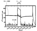
- Example 4 is an explanatory diagram showing the change in ion current value in one embodiment (Example 1) of the present invention.
- the current value of the O 6+ ion beam when O 6+ ions are generated in the ECR ion source 10 is taken as the ion current value.
- the first voltage value V1 is set to ⁇ 160 V
- the second voltage value V2 is set to ⁇ 1000 V ( ⁇ 1 kV)
- the ionization energy supply period Tp is set to 50 msec.
- the auxiliary voltage reduction timing T1 is set 20 msec after the ionization energy supply start timing T3, and the high voltage period Th is set to 1 msec.
- Example 1 As shown in FIG. 4, in Example 1, during the period when the first voltage value V1 is applied, the ion current value is a maximum of about 120 ⁇ A, and during the period when the second voltage value V2 is applied (high voltage period Th), the ion current value increases to about 210 ⁇ A.
- the ion current value is about 20 ⁇ A. Therefore, it was found that the ion current value increases by applying the first voltage value V1, and the ion current value increases by about 70% when the second voltage value V2 is applied compared to when the first voltage value V1 is applied.
- the amount of ions generated can be dramatically increased.
- the electrons flowing out from the plasma 1a can be effectively pushed back to the plasma 1a.
- FIG. 5 is an explanatory diagram showing the change in the ion current value in another embodiment (embodiment 2) of the present invention and a comparative example (comparative example 1).
- the current value of the O 6+ ion beam when O 6+ ions are generated in the ECR ion source 10 is set as the ion current value.
- the ionization energy supply period Tp is set to 50 msec
- the auxiliary voltage reduction timing T1 is set 20 msec after the ionization energy supply start timing T3
- the high voltage period Th is set to 5 msec.
- the first voltage value V1 is set to -160 V
- the second voltage value V2 is set to -1000 V (-1 kV) (same as embodiment 1).
- the first voltage value V1 is set to 0 V
- the second voltage value V2 is set to -1000 V (-1 kV).
- Example 2 similar to Example 1, during the period when the first voltage value V1 was applied, the ion current value was a maximum of about 120 ⁇ A, and during the period when the second voltage value V2 was applied (high voltage period Th), the ion current value increased to about 210 ⁇ A.
- Comparative Example 1 during the period when the second voltage value V2 was not applied (only ionization energy supply), the ion current value was a maximum of about 20 ⁇ A, and even during the period when the second voltage value V2 was applied, the ion current value only increased to about 120 ⁇ A. From the results of Example 2 and Comparative Example 1, it was found that the amount of ions generated can be further increased by changing the voltage over time as a two-level pulse wave of the first voltage value V1 and the second voltage value V2.
- FIG. 6 is an explanatory diagram showing the change in the ion current value in several examples of the present invention and comparative examples.
- FIG. 7 is an explanatory diagram showing the relationship between the auxiliary voltage value VBD and the ion current value in several examples of the present invention and comparative examples.
- FIG. 6 and 7 show the measurement results of the ion current value in Examples 3 to 10 in which the first voltage value V1 was fixed at ⁇ 160 V, different second voltage values V2 were set within the range of ⁇ 200 V to ⁇ 1800 V, the second voltage value V2 was applied, and the auxiliary voltage value VBD was changed over time as a pulse wave, and in Comparative Example 2 in which the second voltage value V2 was not applied (remained at ⁇ 160 V, and the auxiliary voltage value VBD was not changed over time as a pulse wave).
- the display of the ion current values of Examples 8 to 10 is omitted in FIG. 6.
- the second voltage value V2 is -200V
- the second voltage value V2 is -300V
- the second voltage value V2 is -400V
- the second voltage value V2 is -600V
- the second voltage value V2 is -800V
- the second voltage value V2 is -1000V
- the second voltage value V2 is -1200V
- the second voltage value V2 is -1400V.
- the second voltage value V2 is the lowest, and even in Example 3 (second voltage value V2 is -200 V), which is a voltage value that is just over 1.2 times the first voltage value, the maximum ion current value increases. From this, it is possible to make the second voltage value V2 a voltage value that is 1.2 times or more the first voltage value.
- the maximum ion current value increases as the second voltage value V2 increases up to a certain voltage value.
- the maximum ion current value increases as the second voltage value V2 increases up to -800 V.
- the second voltage value V2 be a voltage value that is at least twice the first voltage value, more preferably at least three times the first voltage value, preferably at least four times the first voltage value, and even more preferably at least five times the first voltage value.
- the auxiliary voltage value VBD of the auxiliary voltage applied to the auxiliary electrode 19 is changed over time as a two-level pulse wave of the first voltage value V1 and the second voltage value V2 whose voltage value is lower than the first voltage value V1, thereby making it possible to effectively push back electrons flowing out from the plasma 1a to the plasma 1a and increase the amount of ions generated.
- the present invention can also be used as an ion extraction method in which the auxiliary voltage value VBD of the auxiliary voltage applied to the auxiliary electrode 19 is changed over time as a two-level pulse wave of the first voltage value V1 and the second voltage value V2 whose voltage value is lower than the first voltage value V1.
- the auxiliary voltage reduction timing T1 is set within the ionization energy supply period Tp, so that there is at least a period of overlap between the high voltage period Th and the ionization energy supply period Tp. Therefore, during the period in which the plasma 1a is being generated, electrons that flow out of the plasma 1a can be effectively pushed back into the plasma 1a, thereby increasing the amount of ions generated.
- the auxiliary voltage reduction timing T1 is set after a predetermined time Tg has elapsed from the ionization energy supply start timing T3, and the predetermined time Tg is set according to the time required to increase the amount of ions (particularly multiply charged ions) generated. Therefore, the amount of multiply charged ions generated can be effectively increased.
- the auxiliary voltage rise timing T2 is set within the ionization energy supply period Tp, so that the high voltage period Th does not become longer than necessary, and damage to the auxiliary electrode 19 (damage to the auxiliary electrode 19) can be suppressed.
- the second voltage value V2 can be set to a voltage value that is 1.2 times or more the first voltage value, which can reliably increase the amount of ions generated.
- the auxiliary electrode 19 is inserted into the vacuum opening 11a and is positioned upstream in the plasma chamber 11 (opposite the ion emission opening 11b, or rearward when viewed from the direction of travel of the ion beam), so that electrons flowing out of the plasma 1a can be effectively pushed back to the plasma 1a (the ion emission opening 11b side, i.e., the direction of travel of the ion beam 1b), thereby increasing the amount of ions emitted.
- the ion generating device 1 of the present invention can also be applied to a particle beam generator or particle beam irradiation device (ion beam irradiation device).
- the ion generating device 1 can be applied to a synchrotron that uses a pre-stage accelerator (linear accelerator) and a main accelerator as accelerators, or to a cyclotron that uses only a circular accelerator. Even in these cases, the particle beam can be efficiently generated or irradiated by efficiently extracting the ion beam.
- FIG. 8 is a configuration diagram showing the configuration of an ion beam irradiation device 100 to which the ion generating device 1 of the present invention is applied.
- the ion beam irradiation device 100 of the embodiment shown in FIG. 8 includes a circular accelerator 110 that accelerates the ion beam generated by the ion generating device 1, and an irradiation unit 120 that irradiates the ion beam sent from the circular accelerator 110 to an irradiation target.
- FIG. 9 is a time chart for explaining a modified example of the auxiliary voltage value control method.
- a circular accelerator 110 is provided at the rear (downstream) of the ion generating device 1
- the timing at which the ion beam generated by the ion generating device 1 starts to be injected into the circular accelerator 110 is set as the ion beam injection start timing (fifth timing) T5
- the timing at which the ion beam generated by the ion generating device 1 ends to be injected into the circular accelerator 110 is set as the ion beam injection end timing (sixth timing) T6
- the period (ion beam injection period) from the ion beam injection start timing T5 to the ion beam injection end timing T6 is set as the ion beam injection period Ti.
- the auxiliary voltage drop timing T1 is set before the ion beam injection start timing T5, and the auxiliary voltage rise timing T2 is set after the ion beam injection end timing T6. That is, the auxiliary voltage drop timing T1 and the auxiliary voltage rise timing T2 are set before and after the ion beam injection period Ti so as to sandwich the ion beam injection period Ti. Therefore, the high voltage period Th is set to overlap the entire period of the ion beam injection period Ti. In this way, it is possible to increase the number of ions contained in the ion beam 1b that is injected into the accelerator downstream of the ion generating device 1. Therefore, the amount of ions irradiated per unit time by the ion beam irradiation device 100 can be increased, and the irradiation time to the irradiation target can be shortened.
- the ion generating device of this invention corresponds to the ion generating device 1 of the above embodiment, and similarly, the chamber corresponds to the plasma chamber 11, the gas supply unit corresponds to the gas supply unit 12a and the gas nozzle 12, the ionization energy supply unit corresponds to the microwave power source 13a and the microwave waveguide 13, the auxiliary electrode corresponds to the auxiliary electrode 19, the voltage application unit corresponds to the auxiliary voltage application unit 20, the voltage control unit corresponds to the auxiliary voltage control unit 36, the first opening corresponds to the vacuum drawing opening 11a, the second opening corresponds to the ion emission opening 11b, the accelerator corresponds to the circular accelerator 110, and the irradiation unit corresponds to the irradiation unit 120, but this invention is not limited to this embodiment and can be in various other embodiments. Also, the specific configurations etc. listed in the above embodiment are just examples and can be changed as appropriate depending on the actual product.
- the ion generating device 1 of the present invention can be used in a surface treatment device that uses an ion beam to clean (remove foreign matter) or etch the surface of an electronic component such as a substrate. Even in this case, the surface can be treated efficiently with a simple configuration by efficiently extracting an ion beam with a simple configuration.
- the invention of claim 1 can be an ion generating device comprising: a chamber for generating an ion beam from a gas introduced into a vacuum; a gas supply unit for supplying gas into the chamber; an ionization energy supply unit for supplying ionization energy for ionizing atoms of the gas into the chamber; an auxiliary electrode disposed in the chamber; a voltage application unit for applying a negative auxiliary voltage to the auxiliary electrode; and a voltage control unit for controlling a voltage value of the auxiliary voltage applied from the voltage application unit to the auxiliary electrode, wherein the voltage control unit is configured to change the voltage value of the auxiliary voltage over time as a two-level pulse wave of a first voltage value that is a predetermined voltage value and a second voltage value that is lower than the first voltage value.
- the invention of claim 2 can be an ion generating device as described in claim 1, wherein the voltage control unit changes the voltage value of the auxiliary voltage from the first voltage value to the second voltage value within a period in which the ionization energy is supplied into the chamber by the ionization energy supply unit.
- the invention of claim 3 can be an ion generating device as described in claim 1 or 2, wherein the voltage control unit changes the voltage value of the auxiliary voltage from the first voltage value to the second voltage value after a predetermined time has elapsed since the ionization energy supply unit started to supply the ionization energy into the chamber.
- the invention of claim 4 can be an ion generating device according to claim 1, 2 or 3, wherein the voltage control unit changes the voltage value of the auxiliary voltage from the second voltage value to the first voltage value within a period in which the ionization energy is supplied into the chamber by the ionization energy supply unit.
- the invention of claim 5 can be the ion generating device of any one of claims 1 to 4, wherein the second voltage value is a voltage value that is 1.2 times or more the first voltage value.
- the invention of claim 6 can be an ion generating device described in any one of claims 1 to 5, wherein the chamber has a first opening at one end and a second opening at the other end for emitting ions into the external space of the chamber, and the auxiliary electrode is inserted into the chamber from the first opening.
- the invention of claim 7 can be an ion beam irradiation device comprising an ion generating device according to any one of claims 1 to 6, an accelerator that accelerates the ion beam generated by the ion generating device, and an irradiation unit that irradiates an irradiation target with the ion beam sent from the accelerator.
- This invention can be used in industries that generate ion beams and irradiate targets with the ion beams.
Landscapes
- Chemical & Material Sciences (AREA)
- Engineering & Computer Science (AREA)
- Combustion & Propulsion (AREA)
- Analytical Chemistry (AREA)
- Electron Sources, Ion Sources (AREA)
Priority Applications (1)
| Application Number | Priority Date | Filing Date | Title |
|---|---|---|---|
| JP2025513129A JPWO2024210104A1 (https=) | 2023-04-03 | 2024-04-01 |
Applications Claiming Priority (2)
| Application Number | Priority Date | Filing Date | Title |
|---|---|---|---|
| JP2023060165 | 2023-04-03 | ||
| JP2023-060165 | 2023-04-03 |
Publications (1)
| Publication Number | Publication Date |
|---|---|
| WO2024210104A1 true WO2024210104A1 (ja) | 2024-10-10 |
Family
ID=92971789
Family Applications (1)
| Application Number | Title | Priority Date | Filing Date |
|---|---|---|---|
| PCT/JP2024/013504 Ceased WO2024210104A1 (ja) | 2023-04-03 | 2024-04-01 | イオン発生装置、イオンビーム照射装置およびイオン取り出し方法 |
Country Status (2)
| Country | Link |
|---|---|
| JP (1) | JPWO2024210104A1 (https=) |
| WO (1) | WO2024210104A1 (https=) |
Citations (2)
| Publication number | Priority date | Publication date | Assignee | Title |
|---|---|---|---|---|
| US20140265853A1 (en) * | 2013-03-14 | 2014-09-18 | Varian Semiconductor Equipment Associates, Inc. | System and method for plasma control using boundary electrode |
| JP2019139943A (ja) * | 2018-02-09 | 2019-08-22 | 国立研究開発法人量子科学技術研究開発機構 | イオン源装置、粒子線発生装置、およびイオンビーム生成方法 |
-
2024
- 2024-04-01 WO PCT/JP2024/013504 patent/WO2024210104A1/ja not_active Ceased
- 2024-04-01 JP JP2025513129A patent/JPWO2024210104A1/ja active Pending
Patent Citations (2)
| Publication number | Priority date | Publication date | Assignee | Title |
|---|---|---|---|---|
| US20140265853A1 (en) * | 2013-03-14 | 2014-09-18 | Varian Semiconductor Equipment Associates, Inc. | System and method for plasma control using boundary electrode |
| JP2019139943A (ja) * | 2018-02-09 | 2019-08-22 | 国立研究開発法人量子科学技術研究開発機構 | イオン源装置、粒子線発生装置、およびイオンビーム生成方法 |
Non-Patent Citations (3)
| Title |
|---|
| HILL C. E., KÜCHLER D., WENANDER F., WOLF B. H.: "Effect of a biased probe on the afterglow operation of an ECR4 ion source", REVIEW OF SCIENTIFIC INSTRUMENTS, AMERICAN INSTITUTE OF PHYSICS, 2 HUNTINGTON QUADRANGLE, MELVILLE, NY 11747, vol. 71, no. 2, 1 February 2000 (2000-02-01), 2 Huntington Quadrangle, Melville, NY 11747, pages 863 - 865, XP012038103, ISSN: 0034-6748, DOI: 10.1063/1.1150314 * |
| LEPORIS MAREK, BOGOMOLOV SERGEI L, EFREMOV ANDREI A, LOGINOV VLADIMIR N, MIRONOV VLADIMIR E: "Role of a biased electrode in the production of highly charged ions using the DECRIS 14-3 ion source", NUKLEONIKA, vol. 48, no. 2, 1 January 2003 (2003-01-01), pages S89 - S92, XP093220507 * |
| RUNKEL S., HOHN O., STIEBING K. E., SCHEMPP A., SCHMIDT-BÖCKING H., MIRONOV V., SHIRKOV G.: "Time resolved experiments at the Frankfurt 14 GHz electron cyclotron resonance ion source", REVIEW OF SCIENTIFIC INSTRUMENTS, AMERICAN INSTITUTE OF PHYSICS, 2 HUNTINGTON QUADRANGLE, MELVILLE, NY 11747, vol. 71, no. 2, 1 February 2000 (2000-02-01), 2 Huntington Quadrangle, Melville, NY 11747, pages 912 - 914, XP012038119, ISSN: 0034-6748, DOI: 10.1063/1.1150343 * |
Also Published As
| Publication number | Publication date |
|---|---|
| JPWO2024210104A1 (https=) | 2024-10-10 |
Similar Documents
| Publication | Publication Date | Title |
|---|---|---|
| US7604716B2 (en) | Methods and apparatus for generating high-density plasma | |
| US6768120B2 (en) | Focused electron and ion beam systems | |
| US6896775B2 (en) | High-power pulsed magnetically enhanced plasma processing | |
| JP3328498B2 (ja) | 高速原子線源 | |
| US20100320404A1 (en) | Particle therapy installation | |
| EP3524320A1 (en) | Ion source device, particle beam generation, and ion beam generation method | |
| CN102292792B (zh) | 离子注入中的增强型低能离子束传输 | |
| Faircloth | Ion sources for high-power hadron accelerators | |
| WO2022079993A1 (ja) | 荷電粒子線の入射装置及びその入射方法 | |
| TWI728506B (zh) | 產生鍺離子束以及氬離子束的方法 | |
| JP2000054125A (ja) | 表面処理方法および装置 | |
| JP2932473B2 (ja) | 高周波型荷電粒子加速装置 | |
| WO2024210104A1 (ja) | イオン発生装置、イオンビーム照射装置およびイオン取り出し方法 | |
| Celata et al. | Progress in heavy ion fusion research | |
| WO2001022465A1 (en) | Plasma source of linear ion beam | |
| RU2000132952A (ru) | Способ и устройство для ускорения ионов в плазменных ускорителях холловского типа | |
| JP3064214B2 (ja) | 高速原子線源 | |
| RU2726143C1 (ru) | Источник интенсивных пучков ионов на основе плазмы ЭЦР разряда, удерживаемой в открытой магнитной ловушке | |
| Volkov et al. | Thermionic cathode-grid assembly simulations for rf guns | |
| JP2024086413A (ja) | イオン発生装置、およびイオン取り出し方法 | |
| RU2810726C1 (ru) | Сильноточный непрерывный источник ионных пучков на основе плазмы электронно-циклотронного резонансного разряда, удерживаемой в открытой магнитной ловушке | |
| AU2005200629A1 (en) | High current density ion source | |
| Annaluru et al. | 1+/N+ method: numerical simulation studies and experimental measurements on the SPIRAL1 ECR Charge Breeder | |
| Kazakov et al. | Development of Forevacuum Plasma-Cathode Electron Sources of Pulsed Large-Radius Electron Beams based on a Cathodic Arc | |
| WO2020209210A1 (ja) | イオン生成装置、方法及びプログラム |
Legal Events
| Date | Code | Title | Description |
|---|---|---|---|
| 121 | Ep: the epo has been informed by wipo that ep was designated in this application |
Ref document number: 24784889 Country of ref document: EP Kind code of ref document: A1 |
|
| WWE | Wipo information: entry into national phase |
Ref document number: 2025513129 Country of ref document: JP |
|
| NENP | Non-entry into the national phase |
Ref country code: DE |
|
| 122 | Ep: pct application non-entry in european phase |
Ref document number: 24784889 Country of ref document: EP Kind code of ref document: A1 |