WO2024209994A1 - 画像センサ、データ処理装置、および画像センサシステム - Google Patents
画像センサ、データ処理装置、および画像センサシステム Download PDFInfo
- Publication number
- WO2024209994A1 WO2024209994A1 PCT/JP2024/011878 JP2024011878W WO2024209994A1 WO 2024209994 A1 WO2024209994 A1 WO 2024209994A1 JP 2024011878 W JP2024011878 W JP 2024011878W WO 2024209994 A1 WO2024209994 A1 WO 2024209994A1
- Authority
- WO
- WIPO (PCT)
- Prior art keywords
- data
- event
- information
- unit
- image
- Prior art date
- Legal status (The legal status is an assumption and is not a legal conclusion. Google has not performed a legal analysis and makes no representation as to the accuracy of the status listed.)
- Ceased
Links
Images


Classifications
-
- H—ELECTRICITY
- H04—ELECTRIC COMMUNICATION TECHNIQUE
- H04N—PICTORIAL COMMUNICATION, e.g. TELEVISION
- H04N23/00—Cameras or camera modules comprising electronic image sensors; Control thereof
- H04N23/50—Constructional details
- H04N23/54—Mounting of pick-up tubes, electronic image sensors, deviation or focusing coils
-
- H—ELECTRICITY
- H04—ELECTRIC COMMUNICATION TECHNIQUE
- H04N—PICTORIAL COMMUNICATION, e.g. TELEVISION
- H04N25/00—Circuitry of solid-state image sensors [SSIS]; Control thereof
- H04N25/47—Image sensors with pixel address output; Event-driven image sensors; Selection of pixels to be read out based on image data
Definitions
- the present disclosure relates to an image sensor, a data processing device, and an image sensor system, and in particular to an image sensor, a data processing device, and an image sensor system that are capable of increasing versatility.
- EVS Event-based Vision Sensor
- Patent Document 1 discloses a sensor architecture that can perform sampling in a frame-based, event-based, or hybrid frame-based and event-based manner.
- An image sensor includes an event detection unit that detects the occurrence of an event, which is a change in the luminance of light received by a photodiode, and a data transmission unit that transmits event data indicating the content of the event as part of payload data, which is added to a line, and in a frame structure in which line information related to the event data is stored at the beginning of the payload data.
- a data processing device includes an event detection unit that detects the occurrence of an event, which is a change in the brightness of light received by a photodiode, and a data transmission unit that treats event data indicating the content of the event as part of payload data, adds the event data to a line, and transmits line information related to the event data in a frame structure stored at the beginning of the payload data.
- the data reception unit receives the event data and line information transmitted from an image sensor, and an event-related data processing unit that refers to the line information and performs data processing related to the event detected by the event detection unit on the event data.
- An image sensor system includes an image sensor having an event detection unit that detects the occurrence of an event, which is a change in the brightness of light received by a photodiode, and a data transmission unit that transmits event data indicating the content of the event as part of payload data, which is added to a line, and in a frame structure in which line information related to the event data is stored at the beginning of the payload data, a data reception unit that receives the event data and the line information transmitted from the image sensor, and an event-related data processing unit that refers to the line information and performs data processing on the event data related to the event detected by the event detection unit.
- the occurrence of an event which is a change in the brightness of the light received by the photodiode, is detected, and event data indicating the content of the event is made part of the payload data and added to the line, and line information related to the event data is transmitted in a frame structure stored at the beginning of the payload data.
- the transmitted event data and line information are then received, and the line information is referenced, and data processing related to the event is performed on the event data.
- FIG. 1 is a block diagram showing a configuration example of an embodiment of a sensor system to which the present technology is applied.
- FIG. 1 is a block diagram showing an example of the configuration of an EVS having a three-chip stacked structure.
- FIG. 2 is a diagram showing an example of a frame configuration of one frame of event data.
- FIG. 13 is a diagram showing an example of embedded data arrangement.
- FIG. 11 is a diagram showing a first example of a frame configuration in which three frames of event data are concatenated into one frame.
- FIG. 13 is a diagram showing a second example of a frame configuration in which three frames of event data are concatenated into one frame.
- 13 is a block diagram showing a first exemplary configuration of an additional information generating unit; FIG.
- FIG. 11 is a diagram illustrating a time stamp, the number of frames, and the amount of data.
- FIG. 11A and 11B are diagrams illustrating the presence or absence of flicker and event data.
- FIG. 2 is a diagram showing an example of a frame configuration in which frame information is stored.
- 1 is a block diagram showing a configuration example of a data processing device; 13 is a block diagram showing an example of the configuration of an additional information generating unit compatible with an arbiter type.
- FIG. 11 is a diagram illustrating a process performed by a frame generating unit.
- FIG. FIG. 13 is a block diagram showing a second exemplary configuration of the additional information generating unit.
- FIG. 13 is a diagram showing an example of a frame configuration in which line information is stored.
- FIG. 13 is a diagram showing another example of a frame configuration storing line information.
- 13 is a block diagram showing an example of the configuration of an additional information generating unit compatible with an arbiter type.
- FIG. 13 is a block diagram showing a third exemplary configuration of the additional information generating unit.
- FIG. 2 is a diagram showing an example of a frame configuration in which pixel information is stored.
- FIG. 1 is a diagram illustrating a method for transmitting pixel information.
- 13 is a block diagram showing an example of the configuration of an additional information generating unit compatible with an arbiter type.
- FIG. FIG. 1 is a block diagram showing an example of the configuration of a sensor system capable of switching physical layers in a serializer and a deserializer.
- FIG. 1 is a block diagram showing an example of the configuration of a sensor system capable of switching physical layers in an EVS and a data processing device.
- FIG. 1 is a diagram illustrating a configuration example of an electronic device equipped with an EVS.
- FIG. 2 is a block diagram showing a schematic configuration example of an EVS.
- FIG. 2 is a circuit diagram illustrating an example of a schematic configuration of an event pixel.
- FIG. 2 is a block diagram showing an example of the configuration of a scan-type EVS.
- FIG. 1 is a block diagram showing an example of the configuration of a sensor system including a plurality of sensors.
- FIG. 11 is a diagram showing a first example of a control result of image connection.
- FIG. 11 is a diagram showing a second example of the control result of image connection.
- FIG. 11 is a diagram showing a first example of a control result of image connection.
- FIG. 11 is a diagram showing a third example of the control result of image connection.
- FIG. 11 is a diagram showing a fourth example of the control result of image connection.
- FIG. 13 is a diagram showing a fifth example of the control result of image connection.
- FIG. 2 is an explanatory diagram showing an example of data transmitted by a first transmission method. An explanatory diagram to explain an example of Embedded Data transmitted using the first transmission method.
- FIG. 11 is a block diagram showing a configuration example of a second embodiment of a sensor system to which the present technology is applied. 1 is a diagram showing an example of a frame configuration of one frame's worth of image data, event data, and line information;
- FIG. FIG. 13 is a block diagram showing a fourth exemplary configuration of the additional information generating unit.
- FIG. 11A and 11B are diagrams illustrating operation timing and interference information.
- 13A and 13B are diagrams illustrating an example in which generation of event data is skipped.
- FIG. 2 is a diagram illustrating an example of a pixel array.
- 13 is a block diagram showing an example of the configuration of an additional information generating unit compatible with an arbiter type.
- FIG. 1 is a diagram showing an example of a format used for data transmission in SLVS-EC.
- FIG. 11 is a block diagram showing a second configuration example of the data processing device. This is a diagram explaining data compression and decompression processes using Hcomp coding. This is a diagram explaining data compression and decompression processes using run length coding. This is a diagram explaining data compression and decompression processes using Huffman coding. This is a diagram explaining data compression and decompression processes using Event Distance coding.
- FIG. 1 is a diagram showing an example of use of an image sensor.
- FIG. 1 is a block diagram showing an example of the configuration of an embodiment of a sensor system 11 to which the present technology is applied.
- the sensor system 11 is configured by connecting an EVS 12 and a data processing device 13 via a data bus 14.
- the EVS 12 is an image sensor that detects luminance changes for each pixel as events in real time, and transmits event data indicating the contents of the event to the data processing device 13 via the data bus 14.
- the EVS 12 is composed of a luminance detection unit 21, an event detection unit 22, an additional information generation unit 23, and a data transmission unit 24.
- the EVS 12 may have a stacked structure in which two chips are stacked: a pixel chip 25 in which the luminance detection unit 21 is provided, and a signal processing chip 26 in which the event detection unit 22, the additional information generation unit 23, and the data transmission unit 24 are provided.
- the event detection unit 22 is an analog circuit that serves as an AFE (Analog Front End). Therefore, as shown in FIG. 2, the EVS 12 may have a stacked structure in which three chips are stacked: a pixel chip 25 in which the luminance detection unit 21 is provided, an AFE chip 27 in which the event detection unit 22 is provided, and a logic chip 28 in which the additional information generation unit 23 and the data transmission unit 24 are provided.
- the data processing device 13 is configured, for example, by an application processor or an FPGA (Field Programmable Gate Array).
- the data processing device 13 performs various types of data processing on the event data transmitted from the EVS 12, and acquires various information related to the event.
- the data processing device 13 is configured with a data receiving unit 31 and an event-related data processing unit 32, and details thereof will be described with reference to FIG. 11 described later.
- the data bus 14 transmits and receives data between the EVS 12 and the data processing device 13, for example, in accordance with CSI-2 (Camera Serial Interface-2), an interface standard established by the MIPI (Mobile Industry Processor Interface) Alliance.
- CSI-2 Cara Serial Interface-2
- MIPI Mobile Industry Processor Interface
- the brightness detection unit 21 is configured with a photodiode provided for each pixel, detects the brightness of the light received by the photodiode, and supplies a brightness signal indicating the brightness value to the event detection unit 22.
- Event detection unit 22 detects the occurrence of an event, which is a change in the luminance signal supplied from luminance detection unit 21; for example, it calculates the difference between the luminance value indicated by the luminance signal and a predetermined reference value, and detects the occurrence of an event when the difference exceeds a positive event detection threshold or a negative event detection threshold.
- event detection unit 22 detects the occurrence of an event, it outputs event data indicating the content of the event (for example, data indicating whether the luminance value has changed to the positive or negative side from the reference value).
- the event data output from event detection unit 22 is also referred to as event raw data, where appropriate.
- the additional information generating unit 23 generates various additional information that is additionally provided for the event data based on the event data output from the event detecting unit 22, and supplies the information to the data transmitting unit 24.
- the additional information generating unit 23 can generate, as additional information, frame information, line information, and pixel information, as described below, in addition to the embedded data defined in CSI-2.
- the data transmission unit 24 transmits the event data output from the event detection unit 22 and the additional information supplied from the additional information generation unit 23 to the data processing device 13 in a frame structure that conforms to the standards of the data bus 14.
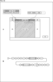
- Figure 3 shows an example of the frame structure of one frame of event data sent from EVS 12 to data processing device 13.
- one frame's worth of event data is stored in multiple long packets arranged in a line between a frame start FS, which is a short packet indicating the start of a frame, and a frame end FE, which is a short packet indicating the end of the frame.
- a long packet containing embedded data is placed at the beginning of the long packet containing the event data.
- a long packet has a packet header PH and a packet footer PF.
- the packet header PH contains a data type DT that indicates the type of data stored in the long packet, and it is possible to distinguish whether embedded data or event data is stored according to the data type DT. Note that the data type DT may be placed in the packet header PH, or at the beginning of the area in the long packet where data is stored.
- event polarity information can be used, which indicates positive P for pixels whose luminance value has changed from the reference value to the positive side, and negative N for pixels whose luminance value has changed from the reference value to the negative side. Note that data other than event polarity information may also be used as event data.
- the position of embedded data is not limited to the beginning of the event data as shown in FIG. 3.
- a frame structure may be used in which multiple pieces of embedded data are placed.
- the insertion position of the embedded data may be the last frame of the event data, as shown in FIG. 4A, or may be the middle frame of the event data, as shown in FIG. 4B.
- a frame configuration can be used in which embedded data is placed both at the beginning and end of the event data.
- the embedded data used is information that is determined at the time the event is acquired, such as a timestamp or number of frames, it is preferable to place the embedded data at the beginning of the event data.
- the embedded data used is information that requires a specific calculation after the event is acquired, such as information related to flicker, optical flow, or thresholds, it is preferable to place the embedded data at the end of the event data.
- multiple event data items corresponding to multiple image data items may be concatenated and transmitted as one frame.
- the frame structure shown in Figure 5 is configured as one frame by not recognizing the frame end FE of the subframe that will be the first event data, the frame start FS and frame end FE of the subframe that will be the second event data, and the frame start FS of the subframe that will be the third event data.
- the event data transmitted between them will be considered as one frame even if they are not actually connected.
- one frame is formed by actually connecting a subframe that is the first event data, a subframe that is the second event data, and a subframe that is the third event data. Note that there may be a gap between these subframes.
- the data receiving unit 31 may be configured to have an internal counter, and by counting the number of subframes in the data receiving unit 31, multiple subframes can be recognized as one frame and event data can be received.
- FIG. 7 is a block diagram showing a first example of the configuration of the additional information generating unit 23. As shown in FIG.
- the additional information generating unit 23 shown in FIG. 7 generates frame information to be added to a frame as additional information that is additionally provided for the event data.
- the frame information is data that only needs to be acquired once in a predetermined period in which the minimum resolution is one frame or more.
- the additional information generating unit 23 generates information on the frame information itself, threshold information, flicker information, movement information, and ROI (Region of Interest) information as frame information.
- information indicating various setting values, event polarity, and data type may also be used as frame information.
- the frame information itself includes a timestamp indicating the time the frame was generated, a frame number indicating which frame it is, and a frame data amount indicating the amount of data that makes up the frame.
- the threshold information includes an event detection threshold (the positive event detection threshold and the negative event detection threshold as described above) that serves as a threshold for detecting the occurrence of an event.
- the flicker information includes information indicating the presence or absence of flicker, the location where the flicker occurs, the intensity of the flicker, and the frequency of the flicker.
- the movement information includes information indicating whether or not the EVS 12 is moving and the direction of movement.
- the ROI information is information that indicates the target region, which is the region in which an event is detected.
- the additional information generating unit 23 is configured with an event access unit 41, an event counting unit 42, an event number analyzing unit 43, an event number frequency analyzing unit 44, an optical flow analyzing unit 45, and a data amount calculating unit 46.
- the event access unit 41 generates a timestamp and frame number and supplies them to the data transmission unit 24.
- the event access unit 41 also instructs the event detection unit 22 when to scan the event data.
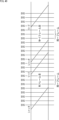
- the event access unit 41 has a circuit for counting the clock clk as shown in FIG. 8, and when it receives an instruction from outside, it can operate according to an internal timer thereafter. For example, the event access unit 41 generates, as a timestamp, the clk count output at the timing when a frame start signal that indicates the start of a frame to the event detection unit 22 is turned on. The event access unit 41 also generates, as the number of frames, a frame count that is counted up at the timing when the timestamp is generated.
- the event counting unit 42 counts the number of times an event has occurred based on the event raw data supplied from the event detection unit 22, and supplies the number of events indicating the count value to the event number analysis unit 43 and the event number frequency analysis unit 44.
- the event number analysis unit 43 analyzes the number of events supplied from the event count unit 42 to set an event detection threshold and generate ROI information, and supplies the event detection threshold and ROI information to the data transmission unit 24.
- the event number analysis unit 43 determines that the current event detection threshold is set low, and sets the event detection threshold high so that events occur at an appropriate frequency. On the other hand, if the number of events is too small, the event number analysis unit 43 determines that the current event detection threshold is set high, and sets the event detection threshold low so that events occur at an appropriate frequency. The event number analysis unit 43 can then feed back the event detection threshold to the event detection unit 22 to adjust the frequency at which events are detected.
- the event detection threshold is normally set from outside the EVS 12, but can be adaptively set inside the EVS 12 by the event number analysis unit 43, and the event detection threshold set by the event number analysis unit 43 needs to be output externally.
- the event number frequency analysis unit 44 analyzes the frequency of the event number supplied from the event count unit 42 to obtain flicker information indicating the presence or absence of flicker, the location where the flicker occurs, the intensity of the flicker, and the frequency of the flicker, and supplies this information to the data transmission unit 24.
- the flicker information represents information about a flicker light source present on the screen.
- FIG. 9A shows an example of event data sampling when no flicker is occurring
- FIG. 9B shows an example of event data sampling when flicker is occurring.
- flicker is occurring due to the blinking of a light source
- positive and negative event data will appear disproportionately due to the blinking.
- flicker information can be obtained by the event count unit 42 and the event number frequency analysis unit 44.
- the optical flow analysis unit 45 performs optical flow analysis to analyze the movement from the luminance information in the image and determine the movement of the object from the velocity vector based on the event raw data supplied from the event detection unit 22. As a result, the optical flow analysis unit 45 obtains information indicating whether or not the EVS 12 is moving and the direction of movement, and supplies this information to the data transmission unit 24.
- the data amount calculation unit 46 calculates the frame data amount, which is the amount of data per frame, based on the event raw data supplied from the event detection unit 22, and supplies it to the data transmission unit 24.
- the data amount calculation unit 46 can calculate the frame data amount based on the en number count value, which is the number of clocks clk counted during the period when the data enable signal data_en is on. Furthermore, when event data for multiple pixels is to be transferred simultaneously, the en number count value can be multiplied by the number of pixels. When the en number count value is 33 and event data for 16 pixels is to be transferred simultaneously, the frame data amount is 528.
- the additional information generation unit 23 can supply the data transmission unit 24 with a timestamp, the number of frames, the event detection threshold, ROI information, flicker information, information indicating whether or not the EVS 12 is moving and the direction of movement, and the amount of frame data.
- the data transmission unit 24 can then store this information as frame information in a frame structure such as that shown in A of FIG. 10, and transmit this together with the event data to the data processing device 13 via the data bus 14.
- B of FIG. 10 shows an example of the output format of the frame information and event data output in accordance with the CSI-2 standard.
- the data transmission unit 24 can store the frame information in accordance with the position of the embedded data in the frame structure described with reference to FIG. 3.
- the frame information may be included as part of the embedded data.
- the frame information may be inserted at the end or middle of the event data, similar to the embedded data shown in FIG. 4 above, or the frame information may be placed at both the beginning and end of the event data.
- the frame information can be stored in the same manner as the embedded data in each subframe.
- the EVS 12 equipped with the additional information generation unit 23 configured as described above employs a frame structure that stores frame information in the same way as embedded data, and can transmit frame information in an output format that conforms to this frame structure. In other words, the EVS 12 transmits frame information as part of the embedded data and event data as part of the payload data in a frame structure. This allows the EVS 12 to be more versatile.
- FIG. 11 is a block diagram showing an example of the configuration of the data processing device 13.
- the data processing device 13 is configured with a data receiving unit 31 and an event-related data processing unit 32.
- the data receiving unit 31 receives frame information and event raw data transmitted from the data transmitting unit 24 in a frame structure as shown in FIG. 10.
- the data receiving unit 31 then supplies the event raw data as is to the event-related data processing unit 32, and also extracts various information contained in the frame information and supplies it to the event-related data processing unit 32. That is, the event-related data processing unit 32 is supplied with a timestamp, number of frames, event detection threshold, ROI information, flicker information, information indicating whether or not the EVS 12 is moving and the direction of movement, and the amount of frame data from the data receiving unit 31.
- the event-related data processing unit 32 can refer to various information contained in the frame information and perform various data processing related to the event detected by the event detection unit 22 on the event raw data supplied from the data receiving unit 31.
- the event-related data processing unit 32 is composed of an ROI calculation processing unit 61, a recognition processing unit 62, an AE/AF processing unit 63, a VLC processing unit 64, a SLAM processing unit 65, an OIE/EIS processing unit 66, a MotionDetect processing unit 67, a Gesture processing unit 68, a Deblur processing unit 69, and a 3DNR processing unit 70.
- an ROI calculation processing unit 61 a recognition processing unit 62, an AE/AF processing unit 63, a VLC processing unit 64, a SLAM processing unit 65, an OIE/EIS processing unit 66, a MotionDetect processing unit 67, a Gesture processing unit 68, a Deblur processing unit 69, and a 3DNR processing unit 70.
- the ROI calculation processing unit 61 performs, for example, ROI calculation processing to obtain coordinate information of the area to be acquired, and outputs the coordinate information of that area.
- the recognition processing unit 62 performs, for example, recognition processing to recognize the object that caused the event, and outputs the recognition result and coordinate information of the object.
- the AE/AF (Auto Exposure/Auto Focus) processing unit 63 outputs distance information indicating the distance to the object that caused the event, which is determined in the AE/AF processing that automatically adjusts the exposure or focus on the object.
- the VLC processing unit 64 performs VLC processing to obtain and output distance information indicating the distance to the target.
- the SLAM (Simultaneous Localization and Mapping) processing unit 65 performs SLAM processing to simultaneously estimate the self-position and create an environmental map, thereby determining and outputting movement amount information indicating the movement amount of the EVS 12 per unit time.
- the OIS/EIS (Optical Image Stabilization/Electronic Image Stabilizer) processing unit 66 outputs movement amount information indicating the movement amount of the EVS 12 per unit time, which is determined in the OIE/EIS processing that performs optical image stabilization or electronic image stabilization.
- the MotionDetect processing unit 67 performs MotionDetect processing to detect the presence or absence of a moving subject within the screen, and outputs information indicating the presence or absence of a moving subject.
- the gesture processing unit 68 performs gesture processing to detect specific actions performed by the subject, and outputs information indicating the detection results (e.g., a waving action, a raising action, etc.).
- the Deblur processing unit 69 outputs movement amount information indicating the amount of movement of the subject per unit time, which is calculated in the Deblur process that removes blur from the subject.
- the 3DNR processing unit 70 outputs coordinate information indicating the coordinates of a moving subject, which is obtained in 3DNR processing that removes three-dimensional noise from the subject.
- Fig. 12 is a block diagram showing a modified example of the first configuration example of the additional information generating unit 23.
- components common to the additional information generating unit 23 in Fig. 7 are denoted by the same reference numerals, and detailed description thereof will be omitted.
- the event detection unit 22 and additional information generation unit 23 shown in FIG. 7 above are of the scan type, and one frame is constructed by outputting event data regardless of whether an event has occurred.
- the additional information generation unit 23' is configured to correspond to an arbiter-type event detection unit 22' that outputs event data only when an event has occurred.
- the additional information generating unit 23' is configured differently from the additional information generating unit 23 in FIG. 7 in that it is configured with a frame generating unit 47.
- the frame generation unit 47 generates one frame of event data by complementing the event data at a timing when no event occurs from the event data output from the arbiter-type event detection unit 22', and supplies it to the event count unit 42, the optical flow analysis unit 45, and the data amount calculation unit 46.
- the frame generation unit 47 also supplies the event raw data to the data transmission unit 24, and supplies the timestamp and frame count of the generated frame to the data transmission unit 24.
- the arbiter-type event detection unit 22' when the nth event occurs, the arbiter-type event detection unit 22' outputs the nth event data (xn, yn, pn, tn) indicating coordinate information and time information at that timing.
- the frame generation unit 47 can temporarily store the event data generated during a certain frame period in SRAM (Static Random Access Memory) 48 according to the coordinate information. Then, when the event data generated during that one frame period is stored in the SRAM, the frame generation unit 47 can output the event data in the form of a frame.
- SRAM Static Random Access Memory
- the arbiter-type event detection unit 22' since the arbiter-type event detection unit 22' does not output event data based on the concept of frames, the arbiter-type EVS 12 must be equipped with a frame generation unit 47.
- Fig. 14 is a block diagram showing a second example of the configuration of the additional information generating unit 23.
- components common to the additional information generating unit 23 in Fig. 7 are denoted by the same reference numerals, and detailed description thereof will be omitted.
- the additional information generating unit 23A shown in FIG. 14 generates line information to be added to a line as additional information that is additionally provided for the event data.
- the additional information generating unit 23A generates, as line information, information on the line itself, identification information for the line, and flicker information.
- the information on the line information itself includes the amount of data (length) of the line information itself, and an identifier for identifying it as line information.
- the identification information for the line includes a timestamp, the coordinates (position) of the line, the amount of data (length) of the line, the number of events on the line (activation rate/attention level), the event detection threshold for the line, the event polarity of the line, the type of data (type including possibilities other than events), information indicating the compression method, or information indicating a signal processing method other than compression applied to the event data.
- the flicker information includes information indicating the presence or absence of flicker on the line, the position where the flicker occurs on the line, the intensity of the flicker on the line, and the frequency of the flicker on the line.
- the line information itself can be added by the data transmission unit 24. A part of this information may be stored in the embedded data.
- the line may be one line or multiple lines. For example, the line information added every 10 lines is inserted as the line information of the first line of the 10 lines.
- Additional information generating unit 23A has a similar configuration to additional information generating unit 23 in FIG. 7 in that it is configured with an event access unit 41, an event count unit 42, an event number analysis unit 43, and an event number frequency analysis unit 44. However, additional information generating unit 23A has a different configuration from additional information generating unit 23 in FIG. 7 in that it is configured with a data amount calculation unit 49 and a data compression unit 50.
- the event access unit 41 generates a timestamp, the coordinates of the line, and the event polarity of the line, and supplies them to the data transmission unit 24.
- the event count analysis unit 43 determines the number of events on the line, sets the event detection threshold for the line, and supplies the event detection threshold for the line and the number of events on the line to the data transmission unit 24.
- the event count frequency analysis unit 44 acquires flicker information for the line, which indicates the presence or absence of flicker on the line, the location where the flicker occurs on the line, the intensity of the flicker on the line, and the frequency of the flicker on the line, and supplies this information to the data transmission unit 24.
- the data amount calculation unit 49 calculates the line data amount, which is the data amount of the line being processed, based on the event raw data supplied from the event detection unit 22, and supplies it to the data transmission unit 24 and the data compression unit 50.
- the data compression unit 50 performs data compression processing to compress the event raw data supplied from the event detection unit 22 using a preset compression method, and supplies the compressed data obtained as a result of this processing to the data transmission unit 24 together with the compression method.
- the additional information generation unit 23A can supply the data transmission unit 24 with the timestamp, the coordinates of the line, the event polarity of the line, the event detection threshold of the line, the number of events of the line, the flicker information of the line, the line data amount of the line, the compressed data, and the compression method.
- the data transmission unit 24 can then store this information as line information in a frame structure such as that shown in A of FIG. 15, and transmit this together with the event data to the data processing device 13 via the data bus 14.
- An example of the line information and event data output in accordance with the CSI-2 standard is shown in B of FIG. 15.
- the data transmission unit 24 stores line information at the beginning of the data storage area (i.e., immediately after the packet header PH) in a long packet that stores event data for each line.
- the line information may be included in the packet header PH. Also, as shown in B of FIG. 16, the data length of the line information is arbitrary.
- the insertion position and number of times of line information are arbitrary, but in consideration of practical use, it is preferable to place the line information at the beginning of the line.
- the line information is information for identifying event data
- the processing efficiency of the event data on the data processing device 13 side can be improved by sending the line information before the event data.
- the data processing device 13 can handle the event data output from EVS 12 while maintaining compatibility with conventional standards.
- the EVS 12 equipped with the additional information generation unit 23A configured as described above employs a frame structure in which line information is stored at a specified position on the line, and can transmit line information in an output format that conforms to this frame structure.
- the EVS 12 transmits the line information in a frame structure in which the frame information is stored at the beginning of the payload data and the event data is part of the payload data. This allows the EVS 12 to be more versatile.
- the data processing device 13 can interpret the packet header PH and the line information, and determine the processing to be performed on the event data based on the contents of the line information.
- Fig. 17 is a block diagram showing a modified example of the second configuration example of the additional information generating unit 23.
- components common to the additional information generating unit 23A in Fig. 14 are denoted by the same reference numerals, and detailed description thereof will be omitted.
- the event detection unit 22 and additional information generation unit 23A shown in FIG. 14 above are of the scan type, and one frame is constructed by outputting event data regardless of whether an event has occurred.
- the additional information generation unit 23A' is configured to correspond to an arbiter-type event detection unit 22' that outputs event data only when an event has occurred.
- the additional information generation unit 23A' has a different configuration from the additional information generation unit 23A in FIG. 14 in that it is configured with a frame generation unit 47.
- the frame generation unit 47 temporarily stores event data that occurs during a certain one-frame period in the SRAM 48, and can output the event data that occurs during that one-frame period in the form of a frame.
- Fig. 18 is a block diagram showing a third example of the configuration of the additional information generating unit 23.
- components common to the additional information generating unit 23 in Fig. 7 are denoted by the same reference numerals, and detailed description thereof will be omitted.
- the additional information generation unit 23B shown in FIG. 18 generates pixel information to be added to pixels as additional information that is additionally provided for the event data.
- the additional information generating unit 23B generates, as pixel information, event information, flicker information, and information derived from the event information.
- Event information includes a timestamp, coordinates, the presence or absence of an event, the polarity of the event that occurred, the event detection threshold, the amount of change in brightness, and the number of events (activation rate).
- Flicker information includes information indicating the presence or absence of flicker, the location where the flicker occurred, the flicker intensity, and the flicker frequency.
- Information derived from the event information is information that is assigned to one pixel or an area spanning multiple pixels by calculation based on the event information for each pixel, and information indicating optical flow, attention level, classification value, etc. is used.
- Additional information generation unit 23B has a similar configuration to additional information generation unit 23 in FIG. 7 in that it is configured to include an event access unit 41, an event count unit 42, an event number analysis unit 43, an event number frequency analysis unit 44, and an optical flow analysis unit 45. Additional information generation unit 23B has a different configuration from additional information generation unit 23 in FIG. 7 in that it is configured to include an attention calculation unit 51 and a data processing unit 52.
- the optical flow analysis unit 45 calculates the optical flow value for each pixel based on the event raw data supplied from the event detection unit 22 and supplies it to the data transmission unit 24.
- the attention calculation unit 51 calculates the attention level of each pixel based on the number of events supplied from the event count unit 42, and supplies the calculated level to the data transmission unit 24.
- the data processing unit 52 is composed of, for example, a neural network, and performs data processing using machine learning based on the event raw data supplied from the event detection unit 22 to determine the classification value and brightness change amount for each pixel, and supplies them to the data transmission unit 24.
- the additional information generation unit 23B can supply the data transmission unit 24 with the timestamp, number of frames, event detection threshold, number of events, flicker information, attention level of each pixel, optical flow value of each pixel, amount of luminance change, presence or absence of an event, and polarity of the event.
- the data transmission unit 24 can then embed this information as pixel information together with event data in the data of each pixel, and store it in a frame structure such as that shown in FIG. 19A.
- FIG. 19B shows an example of output event data (data in which pixel information is embedded for each pixel) output in accordance with the CSI-2 standard.
- the data transmission unit 24 can also insert mode information into the data type DT, which indicates how many bits of data are used for one pixel, depending on the amount of pixel information to be embedded in the pixel data. For example, when the mode information is mode 1, the pixel data amount is 2 bits of 0/-/+, and when the mode information is mode 2, the pixel data amount is the required data amount ⁇ , which is added to the 2 bits of 0/-/+. This makes it possible to flexibly change the output of the EVS 12 depending on the purpose of the application and the amount or precision of information required.
- a in FIG. 20 shows an example of input data input from the event detection unit 22 to the additional information generation unit 23B. For example, “01” is input for positive event data, “10” is input for negative event data, and “00” is input for stay event data with no change in luminance.
- B in Figure 20 shows an example of data when only event data (+/-/stay) is sent using 2 or 3 bits.
- C in Figure 20 shows an example of data when only event data (event/stay) is sent using 2 bits. For example, “00" is input into the event data for stay, and “01” is input into the event data indicating the occurrence of an event.
- D in Figure 20 shows an example of data when pixel information indicating the presence or absence of flicker is transmitted using 2 bits. For example, "00" is input to pixel information indicating no flicker, and "01" is input to pixel information indicating the presence of flicker.
- E in Figure 20 shows an example of data when pixel information indicating the degree of attention is transmitted using 2 bits. For example, "00" is input to pixel information indicating that the area is not of interest, and "01" is input to pixel information indicating that the area is of interest.
- F in Figure 20 shows an example of data when pixel information indicating optical flow values is transmitted using 2 bits.
- This data transmission method allows the EVS 12 to select between sending only the event data, and sending the event data with pixel information added. Furthermore, these selections (selection of data length and content) can be fixed using fuses, ROM, etc., or can be made dynamically selectable on a frame-by-frame basis. When making the selection dynamically selectable on a frame-by-frame basis, for example, frame information stored in the embedded data can be used.
- the EVS 12 equipped with the additional information generating unit 23B configured as described above can employ a frame structure in which pixel information is embedded in the event data, and transmit the pixel information in an output format that conforms to this frame structure. This allows the EVS 12 to be more versatile.
- the data processing device 13 can be configured with a circuit that determines whether or not to switch modes, i.e., how many bits are used in one pixel of data, based on the data acquired from the EVS 12, and generates a switching instruction signal to send to the EVS 12.
- Fig. 21 is a block diagram showing a modified example of the second configuration example of the additional information generating unit 23.
- components common to the additional information generating unit 23B in Fig. 18 are denoted by the same reference numerals, and detailed description thereof will be omitted.
- the event detection unit 22 and additional information generation unit 23B shown in FIG. 18 above are of the scan type, and one frame is constructed by outputting event data regardless of whether an event has occurred.
- the additional information generation unit 23B' is configured to correspond to an arbiter-type event detection unit 22' that outputs event data only when an event has occurred.
- additional information generation unit 23B' has a different configuration from additional information generation unit 23B in FIG. 18 in that it is configured with a frame generation unit 47.
- frame generation unit 47 temporarily stores event data that occurs during a certain one-frame period in SRAM 48, and can output the event data that occurs during that one-frame period in the form of a frame.
- FIG. 22 An example of the configuration of a sensor system 11 capable of switching between a plurality of physical layers will be described with reference to FIGS. 22 and 23.
- FIG. 22 An example of the configuration of a sensor system 11 capable of switching between a plurality of physical layers will be described with reference to FIGS. 22 and 23.
- FIG. 22 An example of the configuration of a sensor system 11 capable of switching between a plurality of physical layers will be described with reference to FIGS. 22 and 23.
- the sensor system 11 can use A-PHY, a SerDes standard for connecting devices within a vehicle with a transmission distance of about 15 m, as a physical layer for transmitting data between the EVS 12 and the data processing device 13.
- the sensor system 11 can also use physical layers other than A-PHY (e.g., C-PHY or D-PHY), and is configured to be able to switch between these physical layers.
- FIG. 22 shows an example configuration of a sensor system 11 in which the serializer and deserializer are provided with a function for switching the physical layer.
- the sensor system 11 is configured to include a serializer 71 and a deserializer 72.
- the sensor system 11 is configured such that communication is performed according to the CSI-2 standard between the EVS 12 and the serializer 71, and between the data processing device 13 and the deserializer 72, and communication is performed between the serializer 71 and the deserializer 72 via the data bus 14.
- the EVS 12 includes a CSI-2 transmission circuit 73 that corresponds to the data transmission unit 24 in FIG. 1, and the data processing device 13 includes a CSI-2 reception circuit 74 that corresponds to the data reception unit 31 in FIG. 1.
- the serializer 71 is configured with a CSI-2 receiving circuit 81, an A-PHY conversion unit 82, a SerDes conversion unit 83, a selector 84, and a SerDes transmitting circuit 85.
- the CSI-2 receiving circuit 81 receives the event data transmitted from the CSI-2 transmitting circuit 73 of the EVS 12 and supplies it to the A-PHY conversion unit 82 and the SerDes conversion unit 83.
- the A-PHY conversion unit 82 serializes the event data supplied from the CSI-2 receiving circuit 81 according to the A-PHY standard and supplies it to the selector 84.
- the SerDes conversion unit 83 serializes the event data supplied from the CSI-2 receiving circuit 81 according to a general SerDes standard other than A-PHY and supplies it to the selector 84.
- the selector 84 selects one of the serially converted event data supplied from the A-PHY conversion unit 82 and the serially converted event data supplied from the SerDes conversion unit 83 according to a predetermined selection signal, for example, and supplies it to the SerDes transmission circuit 85.
- the SerDes transmission circuit 85 transmits the serially converted event data selected by the selector 84 via the data bus 14.
- the deserializer 72 is configured with a SerDes receiving circuit 91, an A-PHY conversion unit 92, a SerDes conversion unit 93, a selector 94, and a CSI-2 transmitting circuit 95.
- the SerDes receiving circuit 91 receives the event data transmitted via the data bus 14 and supplies it to the A-PHY conversion unit 92 and the SerDes conversion unit 93.
- the A-PHY conversion unit 92 performs deserialization on the event data supplied from the SerDes receiving circuit 91 in accordance with the A-PHY standard and supplies it to the selector 94.
- the SerDes conversion unit 93 performs deserialization on the event data supplied from the SerDes receiving circuit 91 corresponding to the serial conversion by the SerDes conversion unit 83 and supplies it to the selector 94.
- the selector 94 selects one of the event data supplied from the A-PHY conversion unit 92 and the event data supplied from the SerDes conversion unit 93 according to a predetermined selection signal, for example, and supplies it to the CSI-2 transmission circuit 95.
- the CSI-2 transmission circuit 95 transmits the event data selected by the selector 94 to the CSI-2 receiving circuit 74 of the data processing device 13.
- the sensor system 11 can switch between serial conversion conforming to the A-PHY standard and serial conversion conforming to a general SerDes standard in the serializer 71 and the deserializer 72. Then, switching between the A-PHY conversion unit 82 and the SerDes conversion unit 83, and switching between the A-PHY conversion unit 92 and the SerDes conversion unit 93 is performed so that the serializer 71 and the deserializer 72 perform serial conversion conforming to the same standard.
- FIG. 23 shows an example configuration of a sensor system 11 in which the EVS 12 and data processing device 13 are provided with a function for switching the physical layer.
- the EVS 12 is configured to include a CSI-2 transmission circuit 73, an A-PHY conversion unit 82, a SerDes conversion unit 83, a selector 84, and a SerDes transmission circuit 85
- the data processing device 13 is configured to include a CSI-2 reception circuit 74, a SerDes reception circuit 91, an A-PHY conversion unit 92, a SerDes conversion unit 93, and a selector 94.
- the sensor system 11 can switch between serial conversion according to the A-PHY standard and serial conversion according to a general SerDes standard in the EVS 12 and data processing device 13. Then, switching between the A-PHY conversion unit 82 and the SerDes conversion unit 83, and switching between the A-PHY conversion unit 92 and the SerDes conversion unit 93 is performed so that the EVS 12 and the data processing device 13 perform serial conversion according to the same standard.
- FIG. 24 is a block diagram showing an example configuration of an electronic device 101 equipped with an EVS 12.
- the electronic device 101 equipped with the EVS 12 is configured with a laser light source 111, an irradiation lens 112, an imaging lens 113, the EVS 12, and a system control unit 114.
- the laser light source 111 is composed of, for example, a vertical cavity surface emitting laser (VCSEL) 122 and a light source driver 121 that drives the VCSEL 122.
- the light source is not limited to the VCSEL 122, and various light sources such as a light emitting diode (LED) may be used.
- the laser light source 111 may be a point light source, a surface light source, or a line light source. In the case of a surface light source or a line light source, the laser light source 111 may have a configuration in which, for example, multiple point light sources (e.g., VCSELs) are arranged one-dimensionally or two-dimensionally. In this embodiment, the laser light source 111 may emit light of a wavelength band different from the wavelength band of visible light, such as infrared (IR) light.
- IR infrared
- the irradiation lens 112 is disposed on the emission surface side of the laser light source 111 and converts the light emitted from the laser light source 111 into irradiation light with a predetermined spread angle.
- the imaging lens 113 is disposed on the light receiving surface side of the EVS 12, and forms an image of the incident light on the light receiving surface of the EVS 12.
- the incident light may include light emitted from the laser light source 111 and reflected by the subject 102.
- the EVS 12 is composed of a light receiving unit 132 in which pixels that detect events (hereinafter referred to as event pixels) are arranged in a two-dimensional grid, and a sensor control unit 131 that drives the light receiving unit 132 to generate frame data based on the event data detected by the event pixels.
- event pixels pixels that detect events
- sensor control unit 131 that drives the light receiving unit 132 to generate frame data based on the event data detected by the event pixels.
- the system control unit 114 is configured, for example, by a processor (CPU), and drives the VCSEL 122 via the light source drive unit 121.
- the system control unit 114 also controls the EVS 12 in synchronization with the control of the laser light source 111, thereby acquiring event data detected in response to the emission/extinction of the laser light source 111.
- the illumination light emitted from the laser light source 111 passes through the illumination lens 112 and is projected onto the subject 102. This projected light is reflected by the subject 102.
- the light reflected by the subject 102 passes through the imaging lens 113 and enters the EVS 12.
- the EVS 12 receives the light reflected by the subject 102 to generate event data, and generates frame data, which is an image, based on the generated event data.
- the frame data generated by the EVS 12 is supplied to the data processing device 13 via the data bus 14.
- the frame data is configured to output a frame header FS indicating the beginning of the frame data, a line header PH indicating the beginning of each line data, a line footer PF indicating the end of each line data, a line data Event sandwiched between the line header PH and the line footer PF, and a frame footer FE indicating the end of the frame data.
- the line data Events of all the lines that make up the frame data are included between the frame header FS and the frame footer FE.
- each line data Event may include event data (e.g., positive event, negative event, or no event) for all the pixels that make up each line, a y address indicating the position of the line, a flag indicating whether the line data is uncompressed data, data compressed using a certain encoding method, or the result of a certain signal processing.
- event data e.g., positive event, negative event, or no event
- the data processing device 13 which is comprised of an application processor or the like, performs predetermined processing, such as image processing and recognition processing, on the frame data input from the EVS 12.
- FIG. 25 is a block diagram showing an example of the general configuration of EVS12.
- the pixel array unit 141, X arbiter 143, and Y arbiter 144 shown in FIG. 25 correspond to the brightness detection unit 21 and arbiter-type event detection unit 22' described above.
- the additional information generation unit 23' described above is incorporated as a function of the event signal processing circuit 142 and system control circuit 145 shown in FIG. 25, and the output interface 146 shown in FIG. 25 corresponds to the data transmission unit 24 described above.
- the EVS 12 is configured with a pixel array section 141, an X arbiter 143, a Y arbiter 144, an event signal processing circuit 142, a system control circuit 145, and an output interface (I/F) 146.
- the pixel array section 141 has a configuration in which a number of event pixels 151, each of which detects an event based on a change in the luminance of incident light, are arranged in a two-dimensional grid.
- the row direction also called the row direction
- the column direction also called the column direction
- Each event pixel 151 has a photoelectric conversion element that generates an electric charge according to the brightness of the incident light, and when it detects a change in the brightness of the incident light based on the photocurrent flowing out of the photoelectric conversion element, it outputs a request to read from itself to the X arbiter 143 and Y arbiter 144, and outputs an event signal indicating that an event has been detected, following arbitration by the X arbiter 143 and Y arbiter 144.
- Each event pixel 151 detects the presence or absence of an event based on whether a change exceeding a predetermined threshold occurs in the photocurrent corresponding to the luminance of the incident light. For example, each event pixel 151 detects an event when the luminance change exceeds a predetermined threshold (positive event) or falls below a predetermined threshold (negative event).
- the event pixel 151 When the event pixel 151 detects an event, it outputs a request to each of the X arbiter 143 and the Y arbiter 144, requesting permission to output an event signal indicating the occurrence of the event. Then, when the event pixel 151 receives a response indicating permission to output the event signal from each of the X arbiter 143 and the Y arbiter 144, it outputs an event signal to the event signal processing circuit 142.
- the X arbiter 143 and the Y arbiter 144 arbitrate requests for the output of an event signal supplied from each of the multiple event pixels 151, and send a response based on the arbitration result (whether or not to permit the output of the event signal) and a reset signal to reset the event detection to the event pixel 151 that output the request.
- the event signal processing circuit 142 performs a predetermined signal processing on the event signal input from the event pixel 151 to generate and output event data.
- Event data indicating the occurrence of an event includes at least position information such as coordinates indicating the position of the event pixel 151 where the change in light amount as an event occurred. In addition to position information, the event data can also include the polarity of the change in light amount.
- the event data can be said to implicitly contain time information that indicates the relative time at which the event occurred.
- the event signal processing circuit 142 may include time information, such as a timestamp, indicating the relative time at which the event occurred in the event data before the interval between the event data is no longer maintained as it was when the event occurred.
- FIG. 26 is a circuit diagram showing an example of the schematic configuration of an event pixel 151. Note that FIG. 26 shows an example of a configuration in which one comparator detects positive events and negative events in a time-division manner.
- events may include, for example, positive events indicating that the amount of change in photocurrent has exceeded an upper threshold, and negative events indicating that the amount of change has fallen below a lower threshold.
- the event data indicating the occurrence of an event may include, for example, one bit indicating the occurrence of an event, and one bit indicating the polarity of the event that has occurred.
- the event pixel 151 may be configured to have the function of detecting only positive events, or the function of detecting only negative events.
- the event pixel 151 includes, for example, a photoelectric conversion unit PD and an address event detection circuit 171.
- the photoelectric conversion unit PD is composed of, for example, a photodiode, and flows out charge generated by photoelectric conversion of incident light as a photocurrent Iphoto. The flowed-out photocurrent Iphoto flows into the address event detection circuit 171.
- the address event detection circuit 171 includes a light receiving circuit 181, a memory capacity 182, a comparator 183, a reset circuit 184, an inverter 185, and an output circuit 186.
- the light receiving circuit 181 is composed of, for example, a current-voltage conversion circuit, and converts the photocurrent Iphoto flowing out from the photoelectric conversion unit PD into a voltage Vpr.
- the relationship between the light intensity (brightness) and the voltage Vpr is usually a logarithmic relationship.
- the light receiving circuit 181 converts the photocurrent Iphoto, which corresponds to the intensity of light irradiated onto the light receiving surface of the photoelectric conversion unit PD, into the voltage Vpr, which is a logarithmic function.
- the relationship between the photocurrent Iphoto and the voltage Vpr is not limited to a logarithmic relationship.
- the voltage Vpr output from the light receiving circuit 181 according to the photocurrent Iphoto passes through the memory capacitance 182 and then becomes the inverted (-) input, which is the first input of the comparator 183, as voltage Vdiff.
- the comparator 183 is usually configured with a differential pair of transistors.
- the comparator 183 uses the threshold voltage Vb provided by the system control circuit 145 as the non-inverted (+) input, which is the second input, and detects positive events and negative events in a time-division manner. After detecting a positive event/negative event, the reset circuit 184 resets the event pixel 151.
- the system control circuit 145 outputs, in a time-division manner, a voltage Von as the threshold voltage Vb when detecting a positive event, a voltage Voff when detecting a negative event, and a voltage Vreset when performing a reset.
- the voltage Vreset is set to a value between the voltages Von and Voff, preferably to a value intermediate between the voltages Von and Voff.
- intermediate value includes not only a value that is strictly intermediate, but also a value that is substantially intermediate, and various variations that arise from design or manufacturing are permitted.
- the system control circuit 145 also outputs an ON selection signal to the event pixel 151 when a positive event is detected, an OFF selection signal when a negative event is detected, and a global reset signal (Global Reset) when a reset is performed.
- the ON selection signal is given as a control signal to a selection switch SWon provided between the inverter 185 and the output circuit 186.
- the OFF selection signal is given as a control signal to a selection switch SWoff provided between the comparator 183 and the output circuit 186.
- the comparator 183 compares the voltage Von with the voltage Vdiff, and when the voltage Vdiff exceeds the voltage Von, it outputs positive event information On as the comparison result, which indicates that the amount of change in the photocurrent Iphoto has exceeded the upper threshold.
- the positive event information On is inverted by the inverter 185 and then supplied to the output circuit 186 via the selection switch SWon.
- the comparator 183 compares the voltage Voff with the voltage Vdiff, and when the voltage Vdiff falls below the voltage Voff, outputs the negative event information Off as the comparison result, which indicates that the amount of change in the photocurrent Iphoto has fallen below the lower threshold.
- the negative event information Off is supplied to the output circuit 186 via the selection switch SWoff.
- the reset circuit 184 includes a reset switch SWRS, a two-input OR circuit 191, and a two-input AND circuit 192.
- the reset switch SWRS is connected between the inverting (-) input terminal and the output terminal of the comparator 183, and when it is turned on (closed), it selectively shorts between the inverting input terminal and the output terminal.
- the OR circuit 191 has two inputs: positive event information On that has passed through the selection switch SWon, and negative event information Off that has passed through the selection switch SWoff.
- the AND circuit 192 has the output signal of the OR circuit 191 as one input, and the global reset signal provided by the system control circuit 145 as the other input, and when either positive event information On or negative event information Off is detected and the global reset signal is in an active state, it turns the reset switch SWRS on (closed).
- the reset switch SWRS shorts between the inverting input terminal and the output terminal of the comparator 183, and performs a global reset on the event pixel 151.
- a reset operation is performed only on the event pixel 151 in which an event has been detected.
- the output circuit 186 has a configuration including a negative event output transistor NM1, a positive event output transistor NM2, and a current source transistor NM3.
- the negative event output transistor NM1 has a memory (not shown) at its gate for holding the negative event information Off. This memory is made up of the gate parasitic capacitance of the negative event output transistor NM1.
- the positive event output transistor NM2 has a memory (not shown) at its gate for holding the positive event information On. This memory is made up of the gate parasitic capacitance of the positive event output transistor NM2.
- the negative event information Off held in the memory of the negative event output transistor NM1 and the positive event information On held in the memory of the positive event output transistor NM2 are transferred to the readout circuit 161 through the output line nRxOff and the output line nRxOn for each pixel row of the pixel array section 141 by a row selection signal being provided from the system control circuit 145 to the gate electrode of the current source transistor NM3.
- the readout circuit 161 is, for example, a circuit provided in the event signal processing circuit 142 (see FIG. 25).
- the event pixel 151 is configured to have an event detection function that uses one comparator 183 to detect positive events and negative events in a time-division manner under the control of the system control circuit 145.
- Figure 27 shows an example of the configuration of a scan-type EVS12'.
- the scan-type EVS12' is configured with an access unit 147 instead of the X arbiter 143 and Y arbiter 144 that the arbiter-type EVS12 shown in FIG. 25 has. That is, the EVS12' has a common configuration with the EVS12 in FIG. 25 in that it has a pixel array unit 141, an event signal processing circuit 142, a system control circuit 145, and an output interface 146.
- the access unit 147 corresponds to, for example, the event access unit 41 in FIG. 7, and instructs each event pixel 151 in the pixel array unit 141 on the timing to scan the event data.
- the EVS 12 described above can be used as all or one or more of the sensors 212 shown in FIG. 28.
- the processor 211 shown in FIG. 28 corresponds to the data processing device 13 described above, and the data bus B1 shown in FIG. 28 corresponds to the data bus 14 described above.
- FIG. 28 is an explanatory diagram showing an example of the configuration of a sensor system 201 according to this embodiment.
- the sensor system 201 include a communication device such as a smartphone, a drone (a device capable of remotely operating or autonomously operating), and a mobile object such as an automobile. Note that application examples of the sensor system 201 are not limited to the examples shown above.
- the sensor system 201 has, for example, a processor 211, multiple sensors 212-1, 212-2, 212-3, ... that have the function of outputting images, a memory 213, and a display device 214.
- the multiple sensors 212-1, 212-2, 212-3, ... may be collectively referred to as “sensor 212", or one of the multiple sensors 212-1, 212-2, 212-3, ... may be representatively referred to as "sensor 212".
- FIG. 28 shows a sensor system 201 having three or more sensors 212
- the number of sensors 212 in the system according to this embodiment is not limited to the example shown in FIG. 28.
- the system according to this embodiment may have any number of sensors 212 greater than or equal to two, such as two sensors 212 or three sensors 212.
- the following will take as examples a case where an image is output from two of the multiple sensors 212 in the sensor system 201, or a case where an image is output from three of the multiple sensors 212 in the sensor system 201.
- the processor 211 and each of the multiple sensors 212 are electrically connected by a single data bus B1.
- the data bus B1 is a signal transmission path that connects the processor 211 and each of the sensors 212.
- image data data representing an image output from each of the sensors 212 (hereinafter, sometimes referred to as "image data") is transmitted from the sensor 212 to the processor 211 via the data bus B1.
- signals transmitted by the data bus B1 are transmitted according to any standard in which the start and end of the transmitted data are specified by specific data, such as the CSI-2 standard or PCI Express.
- specific data include a start packet of a frame in the CSI-2 standard and an end packet of a frame in the CSI-2 standard.
- signals transmitted by the data bus B1 are transmitted according to the CSI-2 standard.
- the processor 211 and each of the multiple sensors 212 are electrically connected by a control bus B2 that is different from the data bus B1.
- the control bus B2 is another signal transmission path that connects the processor 211 and each of the sensors 212.
- control information (described later) output from the processor 211 is transmitted from the processor 211 to the sensor 212 via the control bus B2.
- signals transmitted by the control bus B2 are transmitted in accordance with the CSI-2 standard, similar to the data bus B1.
- FIG. 28 shows an example in which the processor 211 and each of the multiple sensors 212 are connected by one control bus B2, the system according to this embodiment can also be configured in such a way that a control bus is provided for each sensor 212.
- the processor 211 and each of the multiple sensors 212 are not limited to being configured to transmit and receive control information (described later) via the control bus B2, and may be configured to transmit and receive control information (described later) by wireless communication of any communication method capable of transmitting and receiving the control information (described later).
- the processor 211 is composed of one or more processors, which are made up of arithmetic circuits such as an MPU (Micro Processing Unit), and various processing circuits.
- the processor 211 is driven by power supplied from an internal power source (not shown) constituting the sensor system 201, such as a battery, or by power supplied from an external power source of the sensor system 201.
- Processor 211 is an example of a processing device according to this embodiment.
- the processing device according to this embodiment can be applied to any circuit or device capable of performing processing in the processing unit described below (processing related to the control method according to this embodiment).
- the processor 211 performs "control related to the images output via the data bus B1 from each of the multiple sensors 212 connected to the data bus B1 (control related to the control method according to this embodiment)."
- Image-related control is performed, for example, in a processing unit 221 provided in the processor 211.
- a specific processor or a specific processing circuit that performs image-related control, or multiple processors (or multiple processing circuits), serves as the processing unit 221.
- the processing unit 221 is a convenient division of the functions of the processor 211. Therefore, in the processor 211, for example, the control related to the image according to this embodiment may be performed by a plurality of functional blocks. In the following, an example will be given in which the control related to the image according to this embodiment is performed by the processing unit 221.
- the processing unit 221 controls the images by sending control information to each sensor 212.
- the control information according to this embodiment includes, for example, identification information indicating the sensor 212, information for control, and processing instructions.
- the identification information according to this embodiment may be, for example, any data capable of identifying the sensor 212, such as an ID set for the sensor 212.
- control information is transmitted, for example, via control bus B2.
- the control information transmitted by the processing unit 221 is recorded, for example, in a register (an example of a recording medium) provided in each of the sensors 212.
- the sensors 212 then output an image based on the control information stored in the register.
- the processing unit 221 performs control related to the image, for example, one of the control related to the first example shown in (1) below to the control related to the fourth example shown in (4) below. Note that an example of the image output in the sensor system 201 realized by the image control related to this embodiment will be described later.
- the processing unit 221 controls linking of a plurality of images output from each of the sensors 212 .
- the processing unit 221 controls the linking of multiple images, for example, by controlling the start and end of frames in multiple images output from each of the sensors 212.
- the start of a frame in each of the sensors 212 is controlled, for example, by the processing unit 221 controlling the output of a frame start packet in each of the sensors 212.
- An example of a frame start packet is a "Frame Start (FS) packet" in the CSI-2 standard.
- FS Frame Start
- FS packet a frame start packet
- the processing unit 221 controls the output of the start packet of the frame in the sensor 212, for example, by transmitting control information including data indicating whether to output the start packet of the frame (first output information; an example of information for control) to the sensor 212.
- control information including data indicating whether to output the start packet of the frame (first output information; an example of information for control) to the sensor 212.
- An example of the data indicating whether to output the start packet of the frame is a flag indicating whether to output the start packet of the frame.
- the end of the frame in each sensor 212 is controlled, for example, by the processing unit 221 controlling the output of a frame end packet in each sensor 212.
- An example of a frame end packet is a "Frame End (FE) packet" in the CSI-2 standard.
- FE Frame End
- FE packet the frame end packet may be referred to as "FE” or "FE packet”.
- the processing unit 221 controls the output of the end packet of the frame in the sensor 212, for example, by transmitting control information including data indicating whether to output the end packet of the frame (second output information; an example of information for control) to the sensor 212.
- control information including data indicating whether to output the end packet of the frame (second output information; an example of information for control) to the sensor 212.
- An example of the data indicating whether to output the end packet of the frame is a flag indicating whether to output the end packet of the frame.
- the processing unit 221 controls the start and end of a frame in multiple images output from each of the sensors 212, so that data indicating an image such as the one shown below is output from the multiple sensors 212.
- - Data that includes a start packet of a frame and an end packet of a frame
- - Data that includes only a start packet of a frame
- - Data that includes only an end packet of a frame
- - Data that does not include a start packet of a frame and an end packet of a frame
- the processor 211 receives multiple images transmitted from multiple sensors 212 via the data bus B1 and recognizes that image transmission has started for a certain frame based on the frame start packet included in the received images.
- the processor 211 also recognizes that image transmission for a certain frame has ended based on the frame end packet contained in the received image.
- the processor 211 does not recognize that image transmission for a certain frame has started or ended. Note that in the above case, the processor 211 may recognize that image transmission for a certain frame is in progress.
- the processor 211 that receives multiple images transmitted from the multiple sensors 212 via the data bus B1 realizes the processes shown in (a) and (b) below. Note that if another processing circuit capable of processing images is connected to the data bus B1, the images output from the multiple sensors 212 may be processed by the other processing circuit. Below, an example is given of the case where the processing unit 221 included in the processor 211 processes the images output from the multiple sensors 212.
- the processing unit 221 synthesizes an image in the data that includes a start packet of a frame, an image in the data that does not include a start packet of a frame and an end packet of a frame, and an image in the data that includes an end packet of a frame.
- the processing unit 221 synthesizes the images transmitted from the multiple sensors 212 as described above based on the start packet of the frame and the end packet of the frame, thereby realizing the linking of the multiple images transmitted from the multiple sensors 212.
- control of linking multiple images in this embodiment is not limited to the example shown above.
- the processing unit 221 can further control the linking of multiple images by controlling the assignment of identifiers to the multiple images output from each of the sensors 212.
- the identifier in this embodiment is data capable of identifying an image output from the sensor 212.
- Examples of the identifier in this embodiment include one or both of a VC (Virtual Channel) value (sometimes referred to as a "VC number") defined in the CSI-2 standard and a DT (Data Type) value defined in the CSI-2 standard.
- VC Virtual Channel
- DT Data Type
- the identifier in this embodiment is not limited to the above example, and may be any data that can be used to identify an image when controlling the linking of multiple images transmitted from multiple sensors 212.
- the processing unit 221 controls the assignment of an identifier to an image output from the sensor 212, for example, by transmitting control information including data indicating an image identifier (third output information; an example of information for control) to the sensor 212.
- the processing unit 221 recognizes images in a frame that have different identifiers assigned to them as different images. In other words, if the data transmitted from the sensor 212 includes an identifier, the processing unit 221 does not link images that have different identifiers assigned to them.
- processing unit 221 control the assignment of identifiers to the multiple images output from each of the sensors 212, in addition to controlling the start and end of a frame, it becomes possible to realize more diverse control over the linking of images than when controlling the start and end of a frame.
- FIGS. 29 to 33 are explanatory diagrams for explaining an example of image control in the processor 211 constituting the sensor system 201 according to this embodiment.
- Each of FIG. 29 to FIG. 33 shows an example of the control result of image linking in the processor 211.
- FIG. 29 A in Fig. 29 illustrates an example of data corresponding to a certain frame that is acquired by the processor 211 via the data bus B1 from two sensors 212.
- a in Fig. 29 illustrates an example in which the following data is received from one sensor 212 and another sensor 212:
- One sensor 212 data including image data for each line, a start packet of a frame, an end packet of a frame, and a VC value of "0" (an example of an identifier; the same applies below).
- Another sensor 212 data including image data for each line, a start packet of a frame, an end packet of a frame, and a VC value of "1" (an example of an identifier; the same applies below).
- FIG. 29 shows a storage image when the data shown in A in FIG. 29 is stored in the frame buffer of memory 213. Note that the data shown in A in FIG. 29 may be stored in another recording medium, such as a recording medium provided in processor 211.
- the processing unit 221 When data such as that shown in FIG. 29A is received, the processing unit 221 records the image separately in a frame buffer for each VC value, for example as shown in FIG. 29B.
- FIG. 30 A in Fig. 30 illustrates an example of data corresponding to a certain frame that is acquired by the processor 211 via the data bus B1 from two sensors 212.
- a in Fig. 30 illustrates an example in which the following data is received from one sensor 212 and another sensor 212:
- One sensor 212 data including image data for each line, a start packet of a frame, an end packet of a frame, and a VC value of "0"
- Another sensor 212 data including image data for each line, a start packet of a frame, an end packet of a frame, and a VC value of "0"
- the processing unit 221 When data such as that shown in A of FIG. 30 is received, the processing unit 221 records the image in a frame buffer for the same VC value, for example as shown in B of FIG. 30. Storage of the image shown in B of FIG. 30 is achieved, for example, by a double buffer.
- FIG. 31 31A shows an example of data corresponding to a certain frame, which is acquired by the processor 211 via the data bus B1 from two sensors 212.
- 31A shows an example in which the following data is received from one sensor 212 and another sensor 212.
- One sensor 212 data including image data for each line, a start packet of a frame, and a VC value of "0"
- Another sensor 212 data including image data for each line, an end packet of a frame, and a VC value of "0"
- the processing unit 221 concatenates two images vertically, for example as shown in B of FIG. 31, and records the image in the frame buffer.
- FIG. 32 32A shows an example of data corresponding to a certain frame, which is acquired by the processor 211 via the data bus B1 from two sensors 212.
- 32A shows an example in which the following data is received from one sensor 212 and another sensor 212.
- One sensor 212 data including image data for each line, a start packet of a frame, an end packet of a frame, and a VC value of "0"
- Another sensor 212 data including image data for each line, a start packet of a frame, an end packet of a frame, and a VC value of "1"
- the processing unit 221 When data such as that shown in FIG. 32A is received, the processing unit 221 records the image separately in a frame buffer for each VC value, for example as shown in FIG. 32B.
- FIG. 33 33A shows an example of data corresponding to a certain frame, which is acquired by the processor 211 via the data bus B1 from two sensors 212.
- 33A shows an example in which the following data is received from one sensor 212 and another sensor 212.
- One sensor 212 data including image data for each line, a start packet of a frame, and a VC value of "0"
- Another sensor 212 data including image data for each line, an end packet of a frame, and a VC value of "0"
- the processing unit 221 connects two images horizontally, for example as shown in B of FIG. 33, and records the image in the frame buffer.
- control of image linking in the processing unit 221 of the processor 211 selectively links images, for example, as shown in Figures 29 to 33. It goes without saying that examples of the results of image linking control by the processing unit 221 of the processor 100 according to this embodiment are not limited to the examples shown in Figures 29 to 33.
- the processing unit 221 controls the image output from the sensor 212.
- Examples of the control of the image output from the sensor 212 according to this embodiment include one or both of the control of the size of the image output from each sensor 212 and the control of the frame rate of the image output from each of the multiple sensors 212.
- the processing unit 221 controls the image output from the sensor 212 by sending control information to the sensor 212, the control information including, for example, data indicating the image size and/or data indicating the frame rate (an example of information for control).
- the processing unit 221 controls the output timing of images output from each image sensor.
- the processing unit 221 controls the output timing of the image output from the sensor 212, for example, by transmitting control information to the sensor 212, the control information including data indicating the amount of output delay from when an image output command is received until the image is output (an example of information for control).
- the processing unit 221 may perform two or more of the control relating to the first example shown in (1) above to the control relating to the third example shown in (3) above.
- the processing unit 221 performs image-related control, for example, control relating to the first example shown in (1) above to control relating to the fourth example shown in (4) above.
- the processor 211 for example, includes a processing unit 221, and performs processing related to image control as described above (processing related to the control method according to this embodiment).
- the processing performed by the processor 211 is not limited to the processing related to image control as described above.
- the processor 211 can perform various processes, such as processes related to control the recording of image data to a recording medium such as the memory 213 as shown with reference to Figures 29 to 33, processes related to control the display of images on the display screen of the display device 214, and processes for executing any application software.
- An example of a process related to recording control is "processing for transmitting control data including a recording command and data to be recorded on the recording medium to a recording medium such as the memory 213."
- an example of a process related to display control is "processing for transmitting control data including a display command and data to be displayed on the display screen to a display device such as the display device 214.”
- Sensor 212 is an image sensor.
- the image sensor according to this embodiment includes any sensor device, such as an imaging device such as a digital still camera, a digital video camera, or a stereo camera, an infrared sensor, or a distance image sensor, and has a function of outputting a generated image.
- the image generated by sensor 212 corresponds to data indicating the sensing result of sensor 212.
- the sensor 212 is connected to a data bus B1 to which other sensors 212 are connected, for example as shown in FIG. 28.
- the sensor 212 also outputs an image based on the control information. As described above, the control information is transmitted from the processor 211, and the sensor 212 receives the control information via the control bus B2.
- the sensor 212 stores the region information and region data in the payload of a packet and transmits them row by row.
- the additional information generating unit 23 sets region information corresponding to a region set for an image consisting of event data for each row in the image, and transmits the set region information and the event data that becomes the region data corresponding to the region for each row.
- the sensor 212 transmits the region information and region data for each row according to a predetermined order, for example, ascending or descending order of the y coordinate value.
- the sensor 212 may also transmit the region information and region data for each row in a random order.
- the region information is data (data group) for identifying the region set for the image on the receiving device side.
- the region information includes, for example, information indicating the position of the row, identification information of the region included in the row, information indicating the column position of the region included in the row, and information indicating the size of the region included in the row.
- FIG. 34 is an explanatory diagram showing an example of data transmitted by the first transmission method in the transmission method according to this embodiment.
- FIG. 34 shows an example in which "region information and region data (region 1 event data, region 2 event data, region 3 event data, and region 4 event data) corresponding to regions 1, 2, 3, and 4 shown in FIG. 35 are stored in the payload of a MIPI long packet and transmitted row by row.”
- FS in Figure 34 is the FS (Frame Start) packet in the MIPI CSI-2 standard
- FE in Figure 34 is the FE (Frame End) packet in the MIPI CSI-2 standard (the same applies to other figures).
- the "Embedded Data” shown in FIG. 34 is data that can be embedded in the header or footer of the data being transmitted.
- An example of “Embedded Data” is additional information additionally transmitted by the sensor 212.
- Embedded Data may be referred to as "EBD.”
- the additional information may include, for example, one or more of information indicating the amount of data in the area, information indicating the size of the area, and information indicating the priority of the area.
- the information indicating the amount of data in a region may be any format of data that can identify the amount of data in a region, such as "data indicating the number of pixels contained in the region (or the amount of data in the region) and the amount of data in the header."
- the receiving device can identify the amount of data in each region.
- the receiving device can be made to identify the amount of data in a region even if it does not have the function of calculating the amount of data in each region based on the region information.
- Information indicating the size of the region may be, for example, "data indicating a rectangular region that contains the region (e.g., data indicating the number of horizontal and vertical pixels in the rectangular region)" or any other format that can identify the size of the region.
- the information indicating the priority of an area is, for example, data used in processing the data of the area.
- the priority indicated by the information indicating the priority of an area is used in the order in which the areas are processed, and in processing when set areas overlap, such as area 3 and area 4 shown in Figure 35.
- the additional information according to this embodiment is not limited to the example shown above.
- the additional information according to this embodiment may include various data such as exposure information indicating the exposure value in the image sensor device, and gain information indicating the gain in the image sensor device.
- the exposure value indicated by the exposure information and the gain indicated by the gain information are each set in the image sensor device under the control of the processor 211 via the control bus B2.
- Figure 35 is an explanatory diagram for explaining an example of Embedded Data transmitted by the first transmission method in the transmission method according to this embodiment.
- Figure 35 shows an example in which information indicating the size of an area is transmitted as "Embedded Data" shown in Figure 34, and the information indicating the size of the area to be transmitted is data indicating the smallest rectangular area that contains the area.
- Figure 35 also shows an example in which four areas, Area 1, Area 2, Area 3, and Area 4, are set.
- the receiving device can identify the smallest rectangular region that contains region 1 shown in R1 of Figure 35, the smallest rectangular region that contains region 2 shown in R2 of Figure 35, the smallest rectangular region that contains region 3 shown in R3 of Figure 35, and the smallest rectangular region that contains region 4 shown in R4 of Figure 35.
- the information indicating the size of the regions is not limited to data indicating the smallest rectangular region that contains each region.
- the information indicating the priority of an area may be, for example, data in any format that can identify the priority of an area, such as data in which ROI IDs are arranged in order of highest priority, or data in which ROI IDs are arranged in order of lowest priority.
- the receiving device can, for example, identify the order in which the areas will be processed and which area will be given priority for processing. In other words, by transmitting information indicating the priority of an area as "Embedded Data" as shown in Figure 34, the processing of the areas in the receiving device can be controlled.
- PH shown in FIG. 34 is the packet header of a long packet.
- the packet header of a long packet related to the first transmission method may function as data (change information) indicating whether the information contained in the area information has changed from the area information contained in the packet transmitted immediately before.
- "PH" shown in FIG. 34 can be said to be a piece of data indicating the data type of the long packet.
- the sensor 212 sets "PH" to "0x38.” In this case, the sensor 212 stores the area information in the payload of the long packet.
- the sensor 212 sets "PH" to "0x39". In this case, the sensor 212 does not store the region information in the payload of the long packet. In other words, if the information contained in the region information has not changed from the region information contained in the packet transmitted one time previously, the sensor 212 does not transmit the region information.
- Information in Figure 34 is region information stored in the payload (this is the same in other figures). As shown in Figure 34, region information is stored at the beginning of the payload. For example, region information may be indicated as "ROI Info.”
- FIG 34 respectively correspond to area data for area 1, area 2, area 3, and area 4 stored in the payload (this is the same in other figures). Note that in Figure 34, each area data is shown separated, but this is for convenience's sake; the data stored in the payload is not separated (this is the same in other figures). For example, area data may be shown as "ROI DATA”.
- Fig. 36 is a block diagram showing a configuration example of a second embodiment of a sensor system 11 to which the present technology is applied.
- the same reference numerals are used for the configurations common to the sensor system 11 in Fig. 1, and detailed description thereof will be omitted.
- the sensor system 11C is configured by connecting the EVS 12C and the data processing device 13C via the data bus 14.
- the EVS 12C can have a stacked structure in which two chips, a pixel chip 25C and a signal processing chip 26C, are stacked, or it may have a stacked structure in which three chips are stacked, as shown in FIG. 2 above.
- EVS12C has a common configuration with EVS12 in FIG. 1 in that it is configured with a brightness detection unit 21 and an event detection unit 22.
- EVS12C has a different configuration from EVS12 in FIG. 1 in that an image brightness detection unit 29 is provided on the pixel chip 25C, and an additional information generation unit 23C and a data transmission unit 24C are provided on the signal processing chip 26C.
- Data processing device 13C has a different configuration from data processing device 13C in FIG. 1 in that it is configured with a data receiving unit 31C and an event-related data processing unit 32C.
- the image brightness detection unit 29 like the pixels in a normal CIS (CMOS (Complementary Metal Oxide Semiconductor) Image Sensor), detects, for example, the brightness of light for each color transmitted through an RGB color filter, or the brightness of light in all wavelength ranges.
- the image brightness detection unit 29 then supplies an image brightness signal indicating these brightness values to the additional information generation unit 23C. That is, in the pixel chip 25C, the image brightness detection unit 29 outputs an image brightness signal, and the brightness detection unit 21 outputs an EVS brightness signal.
- image data obtained by performing image data processing on the image brightness signal output from the image brightness detection unit 29 is referred to as image data.
- the additional information generating unit 23C Similar to the additional information generating unit 23A in FIG. 14 described above, the additional information generating unit 23C generates line information to be added to the line as additional information additionally provided for the event data, and supplies the line information to the data transmitting unit 24.
- the additional information generating unit 23C generates CIS information as line information in addition to the information on the line itself, the identification information of the line, and the flicker information described above.
- the CIS information uses the frame number of the image data and interference information with the image data, and is generated for each line of the event data.
- the luminance detection unit 21 operates at high speed relative to the operation of the image luminance detection unit 29.
- the frame number of the image data is used to synchronize the event data with the image data.
- the interference information is used to identify event data that has been affected by the interference of the operation of the image luminance detection unit 29 with the operation of the luminance detection unit 21.
- the data transmission unit 24C transmits the event data output from the event detection unit 22, the line information supplied from the additional information generation unit 23, and the image data supplied via the additional information generation unit 23C to the data processing device 13 in a frame structure conforming to the standards of the data bus 14.
- Figure 37 shows an example of the frame configuration of one frame of image data, event data, and line information transmitted from EVS 12C to data processing device 13C.
- the data transmission unit 24C generates transmission data in a frame structure in which image data (CIS) corresponding to one line of an image is alternated with multiple pieces of line information and event data acquired while acquiring the image data.
- the line information is stored at the beginning of the data storage area in a long packet that stores event data (EVS) for each line.
- EVS event data
- a virtual channel can be used to output the line information and event data.
- the process of generating transmission data with such a frame configuration i.e., the process of framing one frame's worth of image data, event data, and line information, is not limited to being performed in the data transmission unit 24C, but may be performed in any of the processing blocks within the signal processing chip 26C. Furthermore, this type of framing process is also the same in the signal processing chip 26 of each of the configuration examples described above.
- the data receiving unit 31C receives image data, event data, and line information transmitted from the data transmitting unit 24 in a frame structure as shown in FIG. 37.
- the data receiving unit 31 then supplies the image data to an image processing unit (not shown), which performs image processing on the image data to construct an image based on the image luminance signal output from the image luminance detection unit 29.
- the data receiving unit 31C also supplies the image data and event data directly to the event-related data processing unit 32C, and extracts various information contained in the line information and supplies it to the event-related data processing unit 32C.
- the event-related data processing unit 32C is configured to include an ROI calculation processing unit 61, a recognition processing unit 62, an AE/AF processing unit 63, a VLC processing unit 64, a SLAM processing unit 65, an OIE/EIS processing unit 66, a MotionDetect processing unit 67, a Gesture processing unit 68, a Deblur processing unit 69, and a 3DNR processing unit 70.
- the event-related data processing unit 32C refers to various information contained in the line information, and performs various data processing operations on the event data supplied from the data receiving unit 31, related to the event detected by the event detection unit 22. Furthermore, when performing data processing on the event data, the event-related data processing unit 32C can synchronize the image data with the event data according to the frame number of the image data, and by performing data processing on the event data while also referring to the image data, it is possible to, for example, improve the accuracy of event detection.
- the line information includes interference information with image data. Therefore, the event-related data processing unit 32C can identify event data that has been affected by interference due to the operation of the image brightness detection unit 29 based on the interference information with image data. The event-related data processing unit 32C can then determine whether or not to use the event data identified based on the interference information with image data in various data processing related to the event. For example, the event-related data processing unit 32C can eliminate the influence of the event data that has been affected by interference due to the operation of the image brightness detection unit 29 by not using the event data in various data processing related to the event, thereby improving the accuracy of event detection.
- Fig. 38 is a block diagram showing a fourth example configuration of the additional information generating unit 23.
- additional information generating unit 23C shown in Fig. 14 components common to the additional information generating unit 23A in Fig. 14 are denoted by the same reference numerals, and detailed description thereof will be omitted.
- Additional information generation unit 23C has a similar configuration to additional information generation unit 23A in FIG. 14 in that it is configured with an event count unit 42, an event number analysis unit 43, an event number frequency analysis unit 44, a data amount calculation unit 49, and a data compression unit 50.
- additional information generation unit 23C has a different configuration from additional information generation unit 23A in FIG. 14 in that it is configured with an event access unit 41C, an image data processing unit 53, and a pixel access unit 54.
- the event access unit 41C Similar to the event access unit 41 described above, the event access unit 41C generates a time stamp, the coordinates of the line, and the event polarity of the line, and supplies them to the data transmission unit 24. Furthermore, the event access unit 41C generates the frame number of the image data and interference information with the image data in response to the timing signal supplied from the pixel access unit 54, and supplies them to the data transmission unit 24C.
- the image data processing unit 53 performs image data processing on the image luminance signal supplied from the image luminance detection unit 29, and supplies the image data (RGB/luminance) obtained as a result of this processing to the data transmission unit 24C.
- the pixel access unit 54 accesses the image brightness detection unit 29 to control the shutter and read of the image brightness detection unit 29, and also supplies timing signals indicating the timing at which these operations were performed to the event access unit 41C.
- Figure 39 shows an example of the timing of operation (shutter and read) of the image brightness detection unit 29 and the timing of operation (detect and read) of the brightness detection unit 21 when acquiring image data for the Nth and N+1th frames.
- the brightness detection unit 21 operates faster than the brightness detection unit 29 for images. In the example shown, while the brightness detection unit 29 for one frame of image is shuttered, the brightness detection unit 21 performs five operations, and event data is acquired for each operation. Similarly, in the example shown, while the brightness detection unit 29 for one frame of image is read, the brightness detection unit 21 performs five operations, and event data is acquired for each operation.
- an asterisk is indicated at the timing when the operation of image luminance detection unit 29 and the operation of luminance detection unit 21 coincide.
- event data acquired at the timing indicated by an asterisk in FIG. 39 i.e., event data acquired at approximately the same timing as the operation of image luminance detection unit 29, is assumed to be affected by the operation of image luminance detection unit 29 interfering with the operation of luminance detection unit 21.
- the pixel access unit 54 then supplies a timing signal indicating the timing at which the image brightness detection unit 29 performed to the event access unit 41C, and the event access unit 41C generates interference information with the image data based on the timing signal. This enables the event-related data processing unit 32C to determine whether or not to use the event data that has been affected by interference due to the operation of the image brightness detection unit 29 in various data processing related to the event.
- the brightness detection unit 21 does not need to be operated at the timing when the image brightness detection unit 29 operates.
- the operation of the luminance detection unit 21 can be stopped for a short period of time before and after the timing that coincides with the operation of the image luminance detection unit 29, and the acquisition of event data at that timing can be skipped.
- the event access unit 41C generates interference information with image data
- the event-related data processing unit 32C recognizes, based on the interference information with image data, that event data has not been acquired at that timing, and can perform various data processing related to the event.
- the frame number of the image data is information that is common to each frame on each line. Therefore, the frame number of the image data in cases where the image brightness detection unit 29 and the brightness detection unit 21 do not operate at approximately the same timing over one frame may be included in the frame information such as EBD.
- the CIS information when all operations of the luminance detection unit 21 belong to the same frame does not include interference information with the image data, but includes the frame number of the image data. Because of this, when all operations of the luminance detection unit 21 belong to the same frame, the CIS information can be included in the line information, as well as in frame information on a frame-by-frame basis such as EBD.
- the individual rectangles shown in FIG. 41 represent multiple pixels arranged in a matrix on the sensor surface of the pixel chip 25C.
- pixels that are provided with a luminance detection unit 21 are referred to as EVS pixels
- pixels that are provided with an image luminance detection unit 29 are referred to as CIS pixels.
- EVS pixels and CIS pixels may be arranged with a uniform density across the entire pixel chip 25C. That is, in the example arrangement shown in FIG. 41A, of the 4 ⁇ 4 array of pixels, EVS pixels are arranged at the top left and bottom right of the central 2 ⁇ 2 array, and CIS pixels are arranged elsewhere, with this arrangement pattern of 4 ⁇ 4 arrays being arranged across the entire pixel chip 25C.
- the positions of the EVS pixels and the CIS pixels may be divided, and the EVS pixels and the CIS pixels may be arranged in the respective regions. That is, in the example arrangement shown in FIG. 41B, the CIS pixels are arranged in the region above the pixel chip 25C, and the EVS pixels are arranged in the region below the pixel chip 25C.
- the arrangement density and arrangement positions of the CIS pixels and EVS pixels arranged on the pixel chip 25C can be set arbitrarily.
- Fig. 42 is a block diagram showing a modified example of the fourth configuration example of the additional information generation unit 23.
- components common to the additional information generation unit 23C in Fig. 36 are denoted by the same reference numerals, and detailed description thereof will be omitted.
- the event detection unit 22 and additional information generation unit 23C shown in FIG. 36 above are of the scan type, and one frame is constructed by outputting event data regardless of whether an event has occurred.
- the additional information generation unit 23C' is configured to correspond to an arbiter-type event detection unit 22' that outputs event data only when an event has occurred.
- additional information generation unit 23C' has a different configuration from additional information generation unit 23C in FIG. 36 in that it is configured with a frame generation unit 47.
- frame generation unit 47 temporarily stores event data that occurs during a certain one-frame period in SRAM 48, and can output the event data that occurs during that one-frame period in the form of a frame.
- SLVS-EC Scalable Low Voltage Signaling with Embedded Clock
- data is transmitted and received between the EVS 12 and the data processing device 13 in accordance with the MIPI CSI-2 standard.
- This technology can be applied to other standards, for example, to SLVS-EC, which is one of the high-speed communication IFs.
- the data transmission unit 24 of the EVS 12 assigns the data of each pixel generated based on the output of the event detection unit 22 to multiple transmission paths, and transmits the data in parallel to the data processing device 13 via multiple transmission paths (e.g., eight transmission paths).
- the transmission paths between the EVS 12 and the data processing device 13 may be wired transmission paths or wireless transmission paths.
- the transmission paths between the EVS 12 and the data processing device 13 will be referred to as lanes as appropriate.
- the data receiving unit 31 of the data processing device 13 receives pixel data transmitted from the data transmitting unit 24 via multiple transmission paths (e.g., eight transmission paths) and outputs the data for each pixel in sequence to the event-related data processing unit 32. In this way, data is transmitted and received between the data transmitting unit 24 and the data receiving unit 31 using multiple lanes.
- multiple transmission paths e.g., eight transmission paths
- the application layer, link layer, and physical layer are defined according to the content of the signal processing.
- Link layer processing and physical layer processing are performed in data transmission unit 24 and data transmission unit 24, respectively.
- the link layer processing includes, for example, processing for realizing the following functions: 1. Pixel data - byte data conversion 2. Payload data error correction 3. Transmission of packet data and auxiliary data 4. Payload data error correction using packet footers 5. Lane management 6. Protocol management for packet generation
- Figure 43 shows an example of a format used for SLVS-EC data transmission.
- the effective pixel area is the area of effective pixels in one frame of an image captured by the pixel chip 25.
- a margin area is located to the left of the effective pixel area.
- a front dummy area is placed above the effective pixel area.
- Embedded Data is placed in the front dummy area.
- the Embedded Data includes information on settings related to imaging by the pixel chip 25, such as shutter speed, aperture value, and gain.
- various additional information such as contents, format, and data size is placed as appropriate as Embedded Data.
- Embedded Data is additional information added to the image data of each frame.
- a rear dummy area is placed below the effective pixel area.
- Embedded Data may be placed in the rear dummy area.
- the image data area is composed of the effective pixel area, margin area, front dummy area, and rear dummy area.
- a header is added before each line that makes up the image data area, and a Start Code is added before the header.
- a footer is optionally added after each line that makes up the image data area, and a control code such as an End Code is added after the footer. If a footer is not added, a control code such as an End Code is added after each line that makes up the image data area.
- data transmission is performed using frame data in the format shown in FIG. 43.
- the upper band in Figure 43 shows the structure of packets used to transmit the frame data shown below. If a horizontal row of data is considered a line, the payload of the packet stores the data that makes up one line of the image data area.
- the entire frame data of one frame is transmitted using packets whose number is equal to or greater than the number of pixels in the vertical direction of the image data area. Furthermore, the entire frame data of one frame is transmitted by sending packets that store data on a line-by-line basis, starting from the data arranged on the top line, for example.
- a packet is constructed by adding a header and footer to a payload that contains one line of data. At least the Start Code and End Code, which are control codes, are added to each packet.
- the header contains additional information about the data stored in the payload, such as Frame Start, Frame End, Line Valid, and Line Number.
- Frame Start is a one-bit piece of information that indicates the beginning of a frame.
- the Frame Start of the header of a packet used to transmit the first line of frame data is set to a value of 1
- the Frame Start of the header of a packet used to transmit other lines of data is set to a value of 0.
- Frame End is a single bit of information that indicates the end of a frame.
- the Frame End in the header of a packet that contains the last line of frame data is set to a value of 1
- the Frame End in the header of a packet that is used to transmit other lines of data is set to a value of 0.
- Line Valid is a single bit of information that indicates whether the line of data stored in the packet is a line in the valid pixel area.
- the value of Line Valid in the header of a packet used to transmit pixel data for a line in the valid pixel area is set to 1, and the value of Line Valid in the header of a packet used to transmit data for other lines is set to 0.
- the Line Number is a 13-bit piece of information that indicates the line number of the line on which the data stored in the packet is located.
- the data transmission unit 24 of the EVS 12 and the data reception unit 31 of the data processing device 13 are high-speed communication IFs that comply with a standard other than SLVS-EC, frame data in which image data for each frame is arranged is generated, and data transmission is performed using packets that store the data for each line of the frame data.
- EVS data when EVS data is output for each frame, in MIPI CSI-2 the EVS data is stored in Embedded Data, while in SLVS-EC the EVS data is stored in Embedded Data in the front dummy area or rear dummy area.
- the Embedded Data shown in the format of Figure 43 refers to the data portion inserted into the dummy area, and when EVS data is stored in the dummy area, that portion becomes Embedded Data.
- EVS data when EVS data is output for each line, in MIPI CSI-2 the EVS data is stored in the packet header, while in SLVS-EC the EVS data is stored in the header's reserve. Or, when EVS data is output for each line, in MIPI CSI-2 the EVS data is stored after the packet header, while in SLVS-EC the EVS data is stored at the beginning of the effective pixels.
- EVS data is output for each pixel, in both MIPI CSI-2 and SLVS-EC, the EVS data is stored in the effective pixel area.
- ECC Error Correction Codes
- CRC Cyclic Redundancy Check
- the payload is area information and area data (for example, the shaded area between PH and PF in Figure 3), and also includes Info.
- the payload is the margin area and valid pixel area
- the packet header corresponds to the Start Code and Header
- the packet footer corresponds to the CRC and End Code.
- the margin area does not have to be provided.
- Fig. 44 is a block diagram showing a second configuration example of the data processing device 13.
- the same components as those in the data processing device 13 in Fig. 11 are denoted by the same reference numerals, and detailed description thereof will be omitted.
- the data compression unit 50 in FIG. 14 described above performs data compression processing on the event raw data supplied from the event detection unit 22 to obtain compressed data, and the compressed data and the compression method used in the data compression processing are included in the line information. Therefore, the data processing device 13 used in combination with the EVS 12 that transmits the compressed data (for example, an EVS 12 equipped with the additional information generation unit 23A in FIG. 14 or the additional information generation unit 23C in FIG. 38) needs to have a function of decompressing the compressed data and restoring it to the original event raw data.
- the data processing device 13A includes an event-related data processing unit 32, similar to the data processing device 13 in FIG. 11, and further includes a data receiving unit 31A and a data decompressing unit 33.
- the data receiving unit 31A has a MIPI decomposition processing unit 34 and a line information processing unit 35.
- the MIPI decomposition processing unit 34 decomposes packets of the MIPI CSI-2 standard and, for example, supplies line information to the line information processing unit 35 and supplies event raw data to the event-related data processing unit 32.
- the MIPI decomposition processing unit 34 may be a packet decomposition unit that decomposes packets of standards other than the MIPI CSI-2 standard, such as the SLVS-EC standard.
- the line information processing unit 35 extracts various information contained in the line information from the line information and supplies the timestamp, coordinates of the line, event polarity of the line, event detection threshold of the line, number of events of the line, flicker information of the line, and amount of line data of the line to the event-related data processing unit 32, and supplies compressed data and compression method to the data decompression unit 33.
- the data receiving unit 31A may also have a frame information processing unit (not shown).
- the MIPI decomposition processing unit 34 decomposes packets conforming to the MIPI CSI-2 standard, and supplies frame information to the frame information processing unit.
- the frame information processing unit extracts various pieces of information contained in the frame information from the MIPI decomposition processing unit 34, and supplies the information to the event-related data processing unit 32 or the data decompression unit 33.
- the data decompression unit 33 decompresses (expands, expands, restores) the compressed data supplied from the data receiving unit 31A using a data decompression process that corresponds to the compression method used in the data compression process by the data compression unit 50, and supplies the resulting uncompressed data, such as the original event raw data, to the event-related data processing unit 32.
- the compressed data is decompressed based on information regarding the compression method included in the line information or frame information.
- Figure 45 is a diagram explaining the data compression and decompression processes when Hcomp coding is used as the compression method.
- Hcomp coding is a compression technique that converts raw event data into a data string that is expressed by the address of the pixel where the event occurred and the event polarity.
- the value indicating the event polarity is set to 0 when the event data is a positive event
- the value indicating the event polarity is set to 1 when the event data is a negative event.
- the event raw data in which a positive event (P) occurs at the 0th address, no event occurs at the 1st to 10th addresses, a negative event (N) occurs at the 11th to 13th addresses, and no event occurs at the 14th and 15th addresses is converted into a data sequence ⁇ (0,0), (11,1), (12,1), (13,1) ⁇ by the data compression unit 50 performing data compression processing using Hcomp coding.
- the first value indicates the x address
- the second value indicates the event polarity.
- the address (y) of the output row is placed at the beginning, followed by a data string consisting of the address (x i ) where the i-th event occurred and the polarity (p i ) of the i-th event. Note that when outputting compressed data for all rows, the address of the output row is not necessary.
- the data decompression unit 33 decompresses the compressed data according to Hcomp coding to obtain the original event raw data.
- the data decompression unit 33 can recognize which address contains which event data of which event polarity (positive event or negative event), and can obtain an image onto which the event data is mapped.
- data compressed using Hcomp coding does not necessarily need to be decompressed; for example, the address at which an event (either a positive event or a negative event) occurred can be used as is as coordinate information.
- the data compression unit 50 can perform data compression processing on the event raw data, and the data decompression unit 33 can perform data decompression processing on the compressed data.
- Figure 46 is a diagram explaining the data compression and decompression processes when run length coding is used as the compression method.
- run length coding is a compression technique that converts raw event data into a data string expressed by the type of data and the number of consecutive occurrences of that data type.
- the value indicating the type of data when no event has occurred is set to 0
- the value indicating the type of data when the event data is a positive event is set to 1
- the value indicating the type of data when the event data is a negative event is set to 2.
- the event raw data in which a positive event (P) occurs at the 0th address, no event occurs at the 1st to 10th addresses, a negative event (N) occurs at the 11th to 13th addresses, and no event occurs at the 14th and 15th addresses is converted into a data sequence ⁇ (1,1), (0,10), (2,3), (0,2) ⁇ by the data compression unit 50 performing data compression processing using run length coding.
- the first value indicates the type of data
- the second value indicates the number of consecutive occurrences of the same type of data.
- the address (y) of the output row is placed at the beginning, followed by a data string consisting of the type (d i ) of the i-th data and the number of consecutive occurrences (c i ) of the i-th data. Note that when outputting compressed data for all rows, the address of the output row is not necessary.
- the data decompression unit 33 decompresses the compressed data according to run length coding to obtain the original event raw data.
- the data decompression unit 33 can recognize how many consecutive event data (no event, positive event, or negative event) are present from the left edge of the image, and can obtain an image onto which the event data is mapped.
- the data compression unit 50 can perform data compression processing on the event raw data, and the data decompression unit 33 can perform data decompression processing on the compressed data.
- Figure 47 is a diagram explaining the data compression and decompression processes when Huffman coding is used as the compression method.
- Huffman coding is a compression technique that converts raw event data into a data string that is expressed according to the frequency of occurrence of the event.
- data when no event has occurred is set to 0
- data when the event data is a positive event is set to 1
- data when the event data is a negative event is set to 2.
- the data compression unit 50 performs data compression processing using Huffman coding to create a frequency table as shown in the figure.
- Ten consecutive zeros, which indicate that an event has not occurred, appears once, and the coded data of ten consecutive zeros becomes 10 ( 2) depending on the frequency of appearance.
- Two consecutive zeros, which indicate that an event has not occurred, appears once, and the coded data of two consecutive zeros becomes 110 ( 6) depending on the frequency of appearance.
- the address (y) of the output row is placed at the beginning, followed by the i-th encoded data (h i ), and then the frequency table for decoding is placed at the end. Note that when outputting compressed data of all rows, the address of the output row is not necessary. Also, one frequency table is provided for each compression unit.
- the data decompression unit 33 decompresses the compressed data according to Huffman coding to obtain the original event raw data.
- the data decompression unit 33 can obtain an image onto which the event data is mapped by applying a predetermined dictionary or rules to the compressed data.
- the data compression unit 50 can perform data compression processing on the event raw data, and the data decompression unit 33 can perform data decompression processing on the compressed data.
- Figure 48 is a diagram explaining the data compression and decompression processes when Event Distance Coding is used as the compression method.
- Event Distance Coding is a compression technique that converts raw event data into a data string that represents the distance between events.
- the value indicating the event polarity is set to 0
- the value indicating the event polarity is set to 1.
- the event raw data in which a positive event (P) occurs at address 0, no event occurs at addresses 1 through 10, a negative event (N) occurs at addresses 11 through 13, and no event occurs at addresses 14 and 15 is converted into a data sequence ⁇ (0,0,1), (10,1,3) ⁇ by data compression processing using Event Distance coding.
- the first value indicates the distance from the previous event
- the second value indicates the polarity of the event
- the third value indicates the number of consecutive events of the same polarity.
- the address of the output row is placed at the beginning, followed by a data string consisting of the distance (d i ) of the i-th event from the immediately preceding event, the polarity (p i ) of the i-th event, and the i-th consecutive number (c i ). Note that when outputting compressed data for all rows, the address of the output row is not necessary.
- the data decompression unit 33 decompresses the compressed data according to the event distance coding to obtain the original event raw data.
- the data decompression unit 33 can recognize how many consecutive event data (no event, positive event, or negative event) are present from the left edge of the image, and can obtain an image onto which the event data is mapped.
- the data compression unit 50 can perform data compression processing on the event raw data, and the data decompression unit 33 can perform data decompression processing on the compressed data.
- the compression method in addition to including the compression method in the line information and sending and receiving it, the compression method can also be included in the frame information and sent and received. For example, when the compression method is the same for the entire frame, the amount of data can be reduced by including the compression method in the frame information.
- FIG. 49 is a diagram showing an example of using the image sensor (EVS12) described above.
- the image sensor described above can be used in a variety of cases, such as sensing visible light, infrared light, ultraviolet light, X-rays, etc., as follows:
- - Devices that take images for viewing such as digital cameras and mobile devices with camera functions
- - Devices used for traffic purposes such as in-vehicle sensors that take images of the front and rear of a car, the surroundings, and the interior of the car for safe driving such as automatic stopping and for recognizing the driver's state, surveillance cameras that monitor moving vehicles and roads, and distance measuring sensors that measure the distance between vehicles, etc.
- - Devices used in home appliances such as TVs, refrigerators, and air conditioners to take images of users' gestures and operate devices in accordance with those gestures
- - Devices used for medical and healthcare purposes such as endoscopes and devices that take images of blood vessels by receiving infrared light
- - Devices used for security purposes such as surveillance cameras for crime prevention and cameras for person authentication
- - Devices used for beauty purposes such as skin measuring devices that take images of the skin and microscopes that take images of the scalp
- - Devices used for sports such as action cameras and wearable cameras for sports purposes, etc.
- the present technology can also be configured as follows.
- an event detection unit that detects the occurrence of an event, which is a change in luminance of light received by the photodiode; and a data transmission unit that transmits event data indicating the content of the event as part of payload data, added to a line, and in a frame structure in which line information related to the event data is stored at the beginning of the payload data.
- the line information is stored in a packet header of a packet that stores the event data defined in CSI-2 or SLVS-EC.
- the line information includes at least one of a timestamp, a coordinate of the line, and an event polarity of the line.
- the line information includes at least one of an event detection threshold for the line and a number of events for the line.
- the line information includes flicker information of the line, the flicker information being generated based on the event data.
- the line information includes a data amount of the line.
- the line information includes at least one of a compression method for compressing the event data and compressed data.
- the line information includes information indicating a signal processing method to be applied to the event data.
- a brightness detection unit that detects the brightness of the light received by the photodiode and outputs a brightness signal indicating the brightness value
- an additional information generating unit configured to generate the line information as additional information additionally provided for the event data based on the event data,
- the event detection unit calculates a difference between the luminance value indicated by the luminance signal and a predetermined reference value, and when the difference exceeds a positive event detection threshold or a negative event detection threshold, detects the occurrence of the event and outputs the event data indicating the content of the event.
- the additional information generating unit includes a frame generating unit that generates a frame from the event data output from the event detecting unit at a timing when an event occurs.
- the additional information generating unit sets area information corresponding to an area set in an image made up of the event data for each row in the image, and transmits the set area information and the event data serving as area data corresponding to the area for each row;
- the additional information generation unit generates, as additional information additionally provided to the event data, a frame number for synchronizing the event data with the image data, and interference information for identifying the event data acquired at approximately the same timing as the timing at which the second brightness detection unit operates.
- the additional information generating unit a pixel access unit that accesses the second luminance detection unit and controls a timing at which the second luminance detection unit operates;
- An event access unit that generates a time stamp used as the line information, coordinates of the line, and an event polarity of the line, and generates the frame number and the interference information based on a timing at which the pixel access unit controls the operation of the second brightness detection unit.
- a data receiving unit that receives the event data and the line information in a frame structure in which event data indicating the content of an event, which is a luminance change of light received by a photodiode, is added to a line as part of payload data and line information related to the event data is stored at the beginning of the payload data; an event-related data processing unit that refers to the line information and processes data related to the event detected by the event detection unit for the event data.
- the data receiving unit receives compressed data obtained by performing a data compression process on the event data, the line information includes information regarding a compression method used in the data compression process;
- the data processing device according to (19) above, further comprising: a data decompression unit that decompresses the compressed data by a data decompression process corresponding to the compression method, and acquires original event data.
- the data receiving unit is region information that is set corresponding to a region set for an image made up of the event data and is set for each row in the image; receiving the event data, which is area data corresponding to the area;
- the data processing device according to claim 19 or 20, wherein the area information includes information indicating a row position and information indicating a column position of the area included in the row.
- a processing unit that is connected to a data bus and performs control related to an image formed from the event data output via the data bus from each of a plurality of image sensors that transmit the event data; the processing unit performs output control of a start packet of a frame in each of the image sensors and output control of an end packet of a frame in each of the image sensors;
- the data processing device according to any one of (19) to (21) above, further comprising control for linking a plurality of images output from each of the image sensors, from an image including a start packet to an image including an end packet.
- an event detection unit that detects the occurrence of an event, which is a change in luminance of light received by the photodiode; a data transmission unit that transmits event data indicating the contents of the event as part of payload data, the event data being added to a line, and line information related to the event data being stored at the beginning of the payload data in a frame structure; and a data receiving unit that receives the event data and the line information transmitted from the image sensor; an event-related data processing unit that refers to the line information and processes data related to the event detected by the event detection unit with respect to the event data.
- (24) Data is serially converted and transmitted between the image sensor and the data processing device;
- region information corresponding to a region set in an image made up of the event data is set for each row in the image, and the set region information and the event data serving as region data corresponding to the region are transmitted for each row; the data receiving unit receives the area information and the event data that becomes the area data;
- the data processing device is connected to a data bus; a processing unit that performs control related to an image formed of the event data output via the data bus from each of the plurality of image sensors connected to the data bus, the processing unit performs output control of a start packet of a frame in each of the image sensors and output control of an end packet of a frame in each of the image sensors;
- an event detection unit that detects the occurrence of an event, which is a change in luminance of light received by the photodiode; and a data transmission unit that transmits the event data indicating the content of the event as part of payload data, and frame information that is added to the frame as additional information additionally provided for the event data as part of embedded data in a frame structure.
- the position of the frame information is the beginning position of the event data consisting of multiple lines, the end position of the event data, an intermediate position of the event data, or the beginning position and the end position of the event data.
- the frame information includes a timestamp or a frame number associated with the event data.
- the frame information includes an event detection threshold or ROI (Region of Interest) information generated based on the event data.
- the frame information includes flicker information generated based on the event data.
- the frame information includes a data amount of the frame.
- the data transmission unit transmits compressed data obtained by performing a data compression process on the event data,
- the event detection unit is an arbiter type
- the data transmission unit sets region information corresponding to a region set in an image consisting of the event data for each row in the image, and transmits the set region information and the event data serving as region data corresponding to the region for each row;
- a brightness detection unit that detects the brightness of the light received by the photodiode and outputs a brightness signal indicating the brightness value; an additional information generating unit configured to generate the frame information as additional information additionally provided for the event data based on the event data,
- the event detection unit calculates a difference between the luminance value indicated by the luminance signal and a predetermined reference value, and when the difference exceeds a positive event detection threshold or a negative event detection threshold, detects the occurrence of the event, and outputs the event data indicating the content of the event.
- a data receiving unit that receives the frame structure in which event data, which indicates the content of an event, which is a luminance change of light received by a photodiode, is treated as a part of payload data, and frame information, which is added to a frame as additional information additionally provided for the event data, is treated as a part of embedded data; an event-related data processing unit that refers to the frame information and processes data related to the event.
- the data receiving unit receives compressed data obtained by performing a data compression process on the event data,
- the data receiving unit is region information that is set corresponding to a region set for an image made up of the event data and is set for each row in the image; receiving the event data, which is area data corresponding to the area;
- the data processing device wherein the area information includes information indicating a row position and information indicating a column position of the area included in the row.
- a processing unit that is connected to a data bus and performs control related to an image formed of the event data outputted via the data bus from each of a plurality of image sensors that output the event data; the processing unit performs output control of a start packet of a frame in each of the image sensors and output control of an end packet of a frame in each of the image sensors;
- the data processing device according to (41) or (42) above, further comprising control for linking a plurality of images output from each of the image sensors, from an image including a start packet to an image including an end packet.
- an event detection unit that detects the occurrence of an event, which is a change in luminance of light received by the photodiode; an image sensor having a data transmission unit that transmits the event data in a frame structure in which the event data indicating the contents of the event is a part of payload data, and frame information added to the frame as additional information additionally provided for the event data is a part of embedded data; a data receiving unit for receiving the event data and the frame information; and an event-related data processing unit that refers to the frame information and processes data related to the event.
- Data is serially converted and transmitted between the image sensor and the data processing device;
- the data transmission unit sets region information corresponding to a region set in an image consisting of the event data for each row in the image, and transmits the set region information and the event data serving as region data corresponding to the region for each row; the data receiving unit receives the area information and the event data that becomes the area data;
- the data processing device includes: a processing unit that is connected to a data bus and performs control related to an image formed of the event data outputted via the data bus from each of the plurality of image sensors that output the event data; the processing unit performs output control of a start packet of a frame in each of the image sensors and output control of an end packet of a frame in each of the image sensors; An image sensor system described in any of (44) to (46) above, which controls the concatenation of multiple images output from each of the image sensors, from an image including a start packet to an image including an end packet.
- an event detection unit that detects the occurrence of an event, which is a change in luminance of light received by the photodiode; a data transmission unit that transmits event data indicating the content of the event as part of payload data, and pixel information added to data for each pixel including the photodiode, in a frame structure embedded in the event data.
- the data transmission unit inserts information indicating an amount of data used in one pixel of data into a data type according to an amount of data of the pixel information to be embedded in the event data.
- the pixel information includes a timestamp or frame number associated with the event data.
- the event detection unit is an arbiter type
- the data transmission unit sets region information corresponding to a region set in an image consisting of the event data for each row in the image, and transmits the set region information and the event data serving as region data corresponding to the region for each row;
- a brightness detection unit that detects the brightness of the light received by the photodiode and outputs a brightness signal indicating the brightness value
- an additional information generating unit configured to generate the pixel information as additional information additionally provided for the event data based on the event data,
- the event detection unit calculates the difference between the luminance value indicated by the luminance signal and a predetermined reference value, and when the difference exceeds a positive event detection threshold or a negative event detection threshold, detects the occurrence of the event, and outputs the event data indicating the content of the event.
- a data receiving unit that receives event data, which indicates the content of an event, which is a luminance change of light received by a photodiode, as part of payload data, in a frame structure in which pixel information added to data for each pixel including the photodiode is embedded in the event data; and an event-related data processing unit that refers to the pixel information and processes data related to the event.
- the data receiving unit is region information that is set corresponding to a region set for an image made up of the event data and is set for each row in the image; receiving the event data, which is area data corresponding to the area;
- the data processing device according to claim 59, wherein the area information includes information indicating a row position and information indicating a column position of the area contained in the row.
- (61) a processing unit that is connected to a data bus and performs control related to an image formed of the event data outputted via the data bus from each of a plurality of image sensors that output the event data; the processing unit performs output control of a start packet of a frame in each of the image sensors and output control of an end packet of a frame in each of the image sensors;
- the data processing device according to (59) or (60) above, wherein control is performed to link a plurality of images output from each of the image sensors, from an image including a start packet to an image including an end packet.
- an event detection unit that detects the occurrence of an event, which is a change in luminance of light received by the photodiode; an image sensor having a data transmission unit that transmits event data indicating the contents of the event as part of payload data, and pixel information added to data for each pixel including the photodiode in a frame structure embedded in the event data; a data receiving unit for receiving the event data and the pixel information; and an event-related data processing unit that refers to the pixel information and processes data related to the event.
- Data is serially converted and transmitted between the image sensor and the data processing device;
- the data transmission unit sets region information corresponding to a region set in an image consisting of the event data for each row in the image, and transmits the set region information and the event data serving as region data corresponding to the region for each row; the data receiving unit receives the area information and the event data that becomes the area data;
- the data processing device includes: a processing unit that is connected to a data bus and performs control related to an image formed of the event data outputted via the data bus from each of the plurality of image sensors that output the event data; the processing unit performs output control of a start packet of a frame in each of the image sensors and output control of an end packet of a frame in each of the image sensors; An image sensor system described in any of (62) to (64) above, which controls the concatenation of multiple images output from each of the image sensors, from an image including a start packet to an image including an end packet.
Landscapes
- Engineering & Computer Science (AREA)
- Multimedia (AREA)
- Signal Processing (AREA)
- Studio Devices (AREA)
Priority Applications (1)
| Application Number | Priority Date | Filing Date | Title |
|---|---|---|---|
| JP2025512510A JPWO2024209994A1 (https=) | 2023-04-07 | 2024-03-26 |
Applications Claiming Priority (2)
| Application Number | Priority Date | Filing Date | Title |
|---|---|---|---|
| JP2023-062502 | 2023-04-07 | ||
| JP2023062502 | 2023-04-07 |
Publications (1)
| Publication Number | Publication Date |
|---|---|
| WO2024209994A1 true WO2024209994A1 (ja) | 2024-10-10 |
Family
ID=92971721
Family Applications (1)
| Application Number | Title | Priority Date | Filing Date |
|---|---|---|---|
| PCT/JP2024/011878 Ceased WO2024209994A1 (ja) | 2023-04-07 | 2024-03-26 | 画像センサ、データ処理装置、および画像センサシステム |
Country Status (2)
| Country | Link |
|---|---|
| JP (1) | JPWO2024209994A1 (https=) |
| WO (1) | WO2024209994A1 (https=) |
Citations (8)
| Publication number | Priority date | Publication date | Assignee | Title |
|---|---|---|---|---|
| JP2017211864A (ja) * | 2016-05-26 | 2017-11-30 | ソニーセミコンダクタソリューションズ株式会社 | 処理装置、画像センサ、およびシステム |
| JP2019091967A (ja) * | 2017-11-10 | 2019-06-13 | ソニーセミコンダクタソリューションズ株式会社 | 送信装置 |
| US20200410272A1 (en) * | 2019-06-26 | 2020-12-31 | Samsung Electronics Co., Ltd. | Vision sensor, image processing device including the vision sensor, and operating method of the vision sensor |
| WO2021215269A1 (ja) * | 2020-04-24 | 2021-10-28 | ソニーセミコンダクタソリューションズ株式会社 | 送信装置、受信装置、および通信システム |
| WO2022009664A1 (ja) * | 2020-07-09 | 2022-01-13 | ソニーグループ株式会社 | 撮像装置及び撮像方法 |
| WO2022152810A1 (en) * | 2021-01-14 | 2022-07-21 | Prophesee | Digital event encoding for operating an event-based image sensor |
| JP2023003308A (ja) * | 2021-06-23 | 2023-01-11 | ソニーセミコンダクタソリューションズ株式会社 | 撮像装置、電子機器、および光検出方法 |
| WO2023058670A1 (ja) * | 2021-10-08 | 2023-04-13 | ソニーセミコンダクタソリューションズ株式会社 | 画像センサ、データ処理装置、および画像センサシステム |
-
2024
- 2024-03-26 JP JP2025512510A patent/JPWO2024209994A1/ja active Pending
- 2024-03-26 WO PCT/JP2024/011878 patent/WO2024209994A1/ja not_active Ceased
Patent Citations (8)
| Publication number | Priority date | Publication date | Assignee | Title |
|---|---|---|---|---|
| JP2017211864A (ja) * | 2016-05-26 | 2017-11-30 | ソニーセミコンダクタソリューションズ株式会社 | 処理装置、画像センサ、およびシステム |
| JP2019091967A (ja) * | 2017-11-10 | 2019-06-13 | ソニーセミコンダクタソリューションズ株式会社 | 送信装置 |
| US20200410272A1 (en) * | 2019-06-26 | 2020-12-31 | Samsung Electronics Co., Ltd. | Vision sensor, image processing device including the vision sensor, and operating method of the vision sensor |
| WO2021215269A1 (ja) * | 2020-04-24 | 2021-10-28 | ソニーセミコンダクタソリューションズ株式会社 | 送信装置、受信装置、および通信システム |
| WO2022009664A1 (ja) * | 2020-07-09 | 2022-01-13 | ソニーグループ株式会社 | 撮像装置及び撮像方法 |
| WO2022152810A1 (en) * | 2021-01-14 | 2022-07-21 | Prophesee | Digital event encoding for operating an event-based image sensor |
| JP2023003308A (ja) * | 2021-06-23 | 2023-01-11 | ソニーセミコンダクタソリューションズ株式会社 | 撮像装置、電子機器、および光検出方法 |
| WO2023058670A1 (ja) * | 2021-10-08 | 2023-04-13 | ソニーセミコンダクタソリューションズ株式会社 | 画像センサ、データ処理装置、および画像センサシステム |
Also Published As
| Publication number | Publication date |
|---|---|
| JPWO2024209994A1 (https=) | 2024-10-10 |
Similar Documents
| Publication | Publication Date | Title |
|---|---|---|
| US20240406575A1 (en) | Image sensor, data processing device, and image sensor system | |
| US20240404282A1 (en) | Image sensor, data processing device, and image sensor system | |
| JP7383616B2 (ja) | イベントベースセンサから信号を出力するための方法、およびそのような方法を使用するイベントベースセンサ | |
| CN109640007B (zh) | 人工智能图像传感设备 | |
| US12267608B2 (en) | Solid-state imaging device and electronic device | |
| WO2023058671A1 (ja) | 画像センサ、データ処理装置、および画像センサシステム | |
| US20180131880A1 (en) | System and method of efficient illuminator-sensor synchronization to capture images | |
| JP2022028982A (ja) | 固体撮像装置、信号処理チップ、および、電子機器 | |
| CN114667725B (zh) | 利用低功率同步读出的传感器 | |
| KR102617485B1 (ko) | 관심 영역 모드 선택을 갖는 송신 장치 및 방법 | |
| KR102641559B1 (ko) | 송신 장치 | |
| JP7152475B2 (ja) | 送信装置、受信装置、及び通信システム | |
| CN114731375B (zh) | 利用同步读出的传感器数据编码 | |
| EP3609175A1 (en) | Apparatus and method for generating moving image data including multiple section images in electronic device | |
| US20220036522A1 (en) | Electronic device, and method for controlling same | |
| US10708524B2 (en) | Methods and apparatus for high dynamic range imaging | |
| KR20240068678A (ko) | 이벤트 검출을 위한 이미지 센서 | |
| CN107563329B (zh) | 图像处理方法、装置、计算机可读存储介质和移动终端 | |
| US20040001074A1 (en) | Image display apparatus and method, transmitting apparatus and method, image display system, recording medium, and program | |
| KR20240036035A (ko) | 센서 디바이스 및 센서 디바이스 작동 방법 | |
| CN117376721B (zh) | 传感器像素单元、信号处理电路和电子设备 | |
| JP2020067534A (ja) | 撮像装置 | |
| CN108805025A (zh) | 激光输出控制方法和装置、电子设备、存储介质 | |
| WO2024209994A1 (ja) | 画像センサ、データ処理装置、および画像センサシステム | |
| CN114766030A (zh) | 用于改进的对象检测的方法和设备 |
Legal Events
| Date | Code | Title | Description |
|---|---|---|---|
| 121 | Ep: the epo has been informed by wipo that ep was designated in this application |
Ref document number: 24784783 Country of ref document: EP Kind code of ref document: A1 |
|
| ENP | Entry into the national phase |
Ref document number: 2025512510 Country of ref document: JP Kind code of ref document: A |
|
| WWE | Wipo information: entry into national phase |
Ref document number: 2025512510 Country of ref document: JP |
|
| NENP | Non-entry into the national phase |
Ref country code: DE |
|
| 122 | Ep: pct application non-entry in european phase |
Ref document number: 24784783 Country of ref document: EP Kind code of ref document: A1 |