WO2024209816A1 - 電力変換装置及びエレベータ制御盤 - Google Patents
電力変換装置及びエレベータ制御盤 Download PDFInfo
- Publication number
- WO2024209816A1 WO2024209816A1 PCT/JP2024/006086 JP2024006086W WO2024209816A1 WO 2024209816 A1 WO2024209816 A1 WO 2024209816A1 JP 2024006086 W JP2024006086 W JP 2024006086W WO 2024209816 A1 WO2024209816 A1 WO 2024209816A1
- Authority
- WO
- WIPO (PCT)
- Prior art keywords
- phase
- power conversion
- conversion circuit
- cooling plate
- outlet
- Prior art date
- Legal status (The legal status is an assumption and is not a legal conclusion. Google has not performed a legal analysis and makes no representation as to the accuracy of the status listed.)
- Ceased
Links
Images




Classifications
-
- H—ELECTRICITY
- H02—GENERATION; CONVERSION OR DISTRIBUTION OF ELECTRIC POWER
- H02M—APPARATUS FOR CONVERSION BETWEEN AC AND AC, BETWEEN AC AND DC, OR BETWEEN DC AND DC, AND FOR USE WITH MAINS OR SIMILAR POWER SUPPLY SYSTEMS; CONVERSION OF DC OR AC INPUT POWER INTO SURGE OUTPUT POWER; CONTROL OR REGULATION THEREOF
- H02M7/00—Conversion of AC power input into DC power output; Conversion of DC power input into AC power output
- H02M7/42—Conversion of DC power input into AC power output without possibility of reversal
- H02M7/44—Conversion of DC power input into AC power output without possibility of reversal by static converters
- H02M7/48—Conversion of DC power input into AC power output without possibility of reversal by static converters using discharge tubes with control electrode or semiconductor devices with control electrode
Definitions
- This disclosure relates to a power conversion device and an elevator control panel.
- a power conversion device that includes multiple semiconductor elements connected in parallel with each other and wiring members such as a bus bar.
- the semiconductor elements are, for example, insulated gate bipolar transistors (IGBTs).
- the bus bar connects each semiconductor element in parallel.
- the bus bar also connects each semiconductor element to a load.
- the load is, for example, a hoist or a motor. If there is a large difference in impedance of the bus bar from each semiconductor element to the load, it becomes difficult to pass a uniform current through each semiconductor element. In other words, a bias may occur in the current flowing through each semiconductor element.
- Such a power conversion device may be applied to an elevator control panel, etc.
- the power converter used in the elevator control panel is required to be configured to be thin due to the constraints of the installation space.
- the three-phase power conversion device described in Japanese Patent No. 5557891 includes a plurality of semiconductor packages (a first-phase first power conversion circuit unit and a first-phase second power conversion circuit unit included in a first-phase unit group), cooling fins (first cooling plates) for air cooling connected to each of the plurality of semiconductor packages, a bus bar (first wiring member), and a capacitor.
- the cooling fins are positioned downwind from the capacitor, and the bus bar is positioned downwind from the cooling fins.
- the capacitor, multiple semiconductor packages, cooling fins, and bus bars are arranged along an air path for cooling in the order described. Therefore, it is difficult to efficiently exhaust heat from the semiconductor packages and cooling fins.
- This disclosure has been made in consideration of the above problems, and its purpose is to provide a power conversion device and elevator control panel that can be made thinner and can efficiently dissipate heat from the first phase unit group and the first cooling plate.
- the power conversion device includes a first phase unit group, a first cooling plate, a first airflow branching wind tunnel, and a first fan.
- the first phase unit group includes a first phase first power conversion circuit unit and a first phase second power conversion circuit unit arranged adjacent to each other in a first direction.
- the first phase first power conversion circuit unit and the first phase second power conversion circuit unit are electrically connected to each other in parallel.
- the first cooling plate is connected to the first phase unit group and arranged side by side with the first phase unit group in a second direction perpendicular to the first direction.
- the first airflow branching wind tunnel is arranged between the first cooling plate and the first fan in a third direction perpendicular to each of the first and second directions.
- the first airflow branching wind tunnel is formed with a first outlet and a second outlet through which air sent from the first fan flows out.
- the first outlet is formed to overlap with the first cooling plate.
- the second outlet is formed to overlap with the surface of the first phase unit group located on the opposite side of the first cooling plate in the second direction and the first space facing that surface.
- the first cooling plate is disposed on the opposite side of the first phase unit group from the first wiring member in the second direction.
- the first wiring member is disposed on the opposite side of the first phase unit group from the first cooling plate in the second direction.
- the first outlet is formed to overlap with the first cooling plate
- the second outlet is formed to overlap with the surface of the first phase unit group located on the opposite side of the first cooling plate in the second direction and the first space facing said surface. This allows for high efficiency exhaust heat from the first phase unit group and the first cooling plate.
- FIG. 1 is a perspective view showing a schematic configuration of a power conversion device according to a first embodiment
- 3 is a perspective view showing schematic configurations of a first-phase first power conversion circuit unit, a first cooling plate, and a bolt of the power conversion device according to the first embodiment.
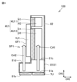
- FIG. 4 is a cross-sectional view for explaining cooling air formed inside a first airflow branch wind tunnel and a main wind tunnel of the power conversion device according to the first embodiment.
- FIG. 2 is a perspective view showing a schematic configuration of a first airflow branching wind tunnel of the power conversion device according to the first embodiment;
- FIG. 1 is a perspective view showing a schematic configuration of an elevator control panel to which a power conversion device according to a first embodiment is applied;
- FIG. 6 is a perspective view showing a schematic configuration of the inside of the control panel shown in FIG. 5 .
- 7 is a cross-sectional view showing a first air passage and a second air passage formed inside the control panel shown in FIGS. 5 and 6 .
- FIG. 1 is a circuit diagram illustrating a schematic configuration of a power conversion device according to a first embodiment.
- 10 is a cross-sectional view showing an outline of an air passage formed inside an elevator control panel to which a power conversion device according to a comparative example is applied.
- FIG. 11 is a perspective view showing a schematic configuration of a power conversion device according to a second embodiment.
- FIG. 13 is a diagram illustrating an example of an arrangement pattern of a plurality of fans in a power conversion device according to a second embodiment.
- FIG. 13 is a cross-sectional view showing a schematic configuration of the inside of a first airflow branching wind tunnel of a power conversion device according to a third embodiment.
- FIG. 13 is a cross-sectional view showing a schematic configuration of the inside of a first airflow branching wind tunnel of a power conversion device according to a fourth embodiment.
- FIG. 13 is a perspective view showing a schematic configuration of a first airflow branching wind tunnel of a power conversion device according to a fourth embodiment.
- 13 is a cross-sectional view showing a schematic configuration of the inside of a first airflow branching wind tunnel of a power conversion device according to a fifth embodiment.
- FIG. FIG. 13 is a perspective view showing a schematic configuration of a first airflow branching wind tunnel of a power conversion device according to a fifth embodiment.
- Embodiment 1 to 8 a configuration of a power conversion device 100 according to a first embodiment will be described.
- the power conversion device 100 is configured as a three-phase power conversion device.
- the power conversion device 100 according to the present embodiment can be applied to a control panel for an elevator.
- the power conversion device 100 mainly includes a first phase unit group 1U, a first bus bar 2U (first wiring member), a first cooling plate 4U, a plurality of first fans 7U, and a plurality of first airflow branching wind tunnels 81U.
- the power conversion device 100 includes a second phase unit group 1V, a third phase unit group 1W, a second bus bar 2V (second wiring member), a third bus bar 2W, a fourth bus bar 3U, a fifth bus bar 3V, a sixth bus bar 3W, a second cooling plate 4V, a third cooling plate 4W, a conductor portion 5, a plurality of bolts 6, a plurality of second fans 7V, a plurality of third fans 7W, a plurality of second airflow branching wind tunnels 81V, a plurality of third airflow branching wind tunnels 81W, and a main wind tunnel 82.
- a control device such as a board is arranged on the front surface where the bus bars are arranged.
- the bolt 6 is indicated by a double circle.
- the first airflow branch wind tunnel 81U and the main wind tunnel 82 are omitted.
- the first bus bar 2U and the fourth bus bar 3U are omitted.
- the first phase unit group 1U, the second phase unit group 1V, and the third phase unit group 1W are configured to input and output U-phase, V-phase, and W-phase, respectively.
- the first phase unit group 1U, the second phase unit group 1V, and the third phase unit group 1W have the same shape as each other.
- the first bus bar 2U to the sixth bus bar 3W have the same shape as each other.
- the first cooling plate 4U, the second cooling plate 4V, and the third cooling plate 4W have the same shape as each other.
- the first fans 7U, the second fans 7V, and the third fans 7W have the same shape as each other.
- the first airflow branching wind tunnels 81U, the second airflow branching wind tunnels 81V, and the third airflow branching wind tunnels 81W each have the same shape as each other.
- the first-phase unit group 1U includes a first-phase first power conversion circuit unit 1U1 and a first-phase second power conversion circuit unit 1U2.
- the first-phase unit group 1U may be configured as two parallel units by the first-phase first power conversion circuit unit 1U1 and the first-phase second power conversion circuit unit 1U2.
- the first-phase unit group 1U may further include a first-phase third power conversion circuit unit 1U3.
- the first-phase unit group 1U is configured as three parallel units by the first-phase first power conversion circuit unit 1U1, the first-phase second power conversion circuit unit 1U2, and the first-phase third power conversion circuit unit 1U3.
- the first-phase unit group 1U is three parallel units.
- Each of the first-phase first power conversion circuit unit 1U1 to the first-phase third power conversion circuit unit 1U3 is configured as a power conversion circuit unit for one phase and one parallel unit.
- the power conversion circuit units of the first-phase unit group 1U have the same shape as each other.
- the first-phase first power conversion circuit unit 1U1, the first-phase second power conversion circuit unit 1U2, and the first-phase third power conversion circuit unit 1U3 are arranged next to each other in the first direction DR1 in the order described above.
- the first-phase third power conversion circuit unit 1U3 is arranged adjacent to the first-phase second power conversion circuit unit 1U2 on the opposite side of the first-phase first power conversion circuit unit 1U1 with respect to the first-phase second power conversion circuit unit 1U2.
- the first cooling plate 4U is arranged so as to overlap the first phase unit group 1U in the second direction DR2.
- the direction in which the first input side semiconductor module 1U11 and the first output side semiconductor module 1U12 described below are arranged is the third direction DR3.
- the first direction DR1, the second direction DR2, and the third direction DR3 intersect with each other.
- the first direction DR1, the second direction DR2, and the third direction DR3 are perpendicular to each other.
- the first direction DR1 and the second direction DR2 are horizontal directions
- the third direction DR3 is vertical directions.
- the first-phase first power conversion circuit unit 1U1 includes a first input side semiconductor module 1U11, a first output side semiconductor module 1U12, a first-phase first capacitor 1U13, and a first-phase first board 1U14.
- the first-phase first power conversion circuit unit 1U1 is configured to pass current in the order of the first input side semiconductor module 1U11, the first-phase first capacitor 1U13, and the first output side semiconductor module 1U12, or in the order of the first output side semiconductor module 1U12, the first-phase first capacitor 1U13, and the first input side semiconductor module 1U11.
- the input side semiconductor modules of each power conversion circuit unit have the same shape.
- the output side semiconductor modules of each power conversion circuit unit have the same shape.
- the capacitors of each power conversion circuit unit have the same shape.
- the boards of each power conversion circuit unit have the same shape.
- the first output side semiconductor module 1U12 is electrically connected to the first input side semiconductor module 1U11 via the first phase first capacitor 1U13.
- the first phase first capacitor 1U13 is electrically connected to the first input side semiconductor module 1U11.
- the first phase first capacitor 1U13 is mounted on the first phase first board 1U14. Therefore, the first phase first capacitor 1U13 is mounted on the board.
- the first input side semiconductor module 1U11 and the first output side semiconductor module 1U12 are configured, for example, as a 2-in-1 package in which two insulated gate bipolar transistors (IGBTs) are built into one package.
- the first input side semiconductor module 1U11 and the first output side semiconductor module 1U12 are not limited to 2-in-1 packages, and 1-in-1 packages or the like may also be used. In this case, the packages are connected, for example, by bus bars.
- the first input side semiconductor module 1U11 and the first output side semiconductor module 1U12 may be configured as metal oxide semiconductor field effect transistors (MOSFETs) or transistors.
- MOSFETs metal oxide semiconductor field effect transistors
- Types of the first phase first capacitor 1U13 include, for example, a film capacitor and an electrolytic capacitor.
- the type of the first phase first capacitor 1U13 may be determined appropriately depending on the application.
- a plurality of capacitors may be mounted on the first phase first board 1U14 in a state of being connected in series or parallel.
- the first phase first capacitor 1U13 is mounted on the first phase first board 1U14 by, for example, soldering.
- the first phase first substrate 1U14 is fixed to the first input side semiconductor module 1U11 and the first output side semiconductor module 1U12 by through holes and male screws provided in the substrate. Through holes in the first phase first substrate 1U14 may be used as the through holes.
- the first phase first substrate 1U14 may be fixed to the first input side semiconductor module 1U11 and the first output side semiconductor module 1U12 by terminals connected to the first phase first substrate 1U14.
- the terminals are made of a metal having high conductivity, such as copper (Cu) or aluminum (Al).
- the first phase first substrate 1U14 is, for example, a printed circuit board.
- the first phase first substrate 1U14 may be, for example, a laminate bus bar in which a bus bar and an insulating film are combined.
- the second phase unit group 1V and the third phase unit group 1W have the same configuration as the first phase unit group 1U.
- Each power conversion circuit unit has the same input side semiconductor module and the same output side semiconductor module. In this case, the structure of each power conversion circuit unit can be made common. Therefore, the manufacturing cost of the power conversion device 100 can be reduced by standardizing the manufacturing and assembly work of each power conversion circuit unit.
- the power conversion device 100 since the power conversion device 100 is a three-phase power conversion device, the power conversion device 100 includes at least three power conversion circuit units. In this embodiment, since the power conversion device 100 is a three-phase three-parallel power conversion device, the power conversion device 100 includes nine power conversion circuit units. If the power conversion device 100 is a three-phase two-parallel power conversion device, the power conversion device 100 includes six power conversion circuit units.
- first busbar 2U to sixth busbar 3W are wiring members for inputting and outputting current.
- the first busbar 2U to the third busbar 2W are input side wiring members.
- the fourth busbar 3U to the sixth busbar 3W are output side wiring members.
- the first busbar 2U to the third busbar 2W are main power supply side wiring members, and the fourth busbar 3U to the sixth busbar 3W are hoisting machine side wiring members.
- the first busbar 2U to the sixth busbar 3W are arranged in the same plane.
- the first busbar 2U is arranged only on the opposite side of the first phase unit group 1U to the first cooling plate 4U.
- the first busbar 2U is arranged in the same plane on the opposite side of the first phase unit group 1U to the first cooling plate 4U.
- the first busbar 2U is configured as a flat plate.
- the first busbar 2U is easier to implement than when the first busbar 2U is configured three-dimensionally.
- the first busbar 2U has a shape that is linearly symmetrical with respect to the second direction DR2.
- the first bus bar 2U electrically connects the first-phase first power conversion circuit unit 1U1 to the first-phase second power conversion circuit unit 1U2.
- the first bus bar 2U electrically connects the first-phase first power conversion circuit unit 1U1, the first-phase second power conversion circuit unit 1U2, and the first-phase third power conversion circuit unit 1U3 in parallel with each other.
- the first busbar 2U includes a first-phase first connection portion 2U1, a first-phase second connection portion 2U2, and a first-phase third connection portion 2U3.
- the first-phase first connection portion 2U1 is electrically connected to the first-phase first power conversion circuit unit 1U1.
- the first-phase second connection portion 2U2 is electrically connected to the first-phase first connection portion 2U1.
- the first-phase second connection portion 2U2 is electrically connected to the first-phase second power conversion circuit unit 1U2.
- the first-phase third connection portion 2U3 is electrically connected to the first-phase second connection portion 2U2.
- the first-phase third connection portion 2U3 is electrically connected to the first-phase third power conversion circuit unit 1U3.
- the first busbar 2U is provided with a first input side terminal 2U0.
- the first input side terminal 2U0 is connected to an electric wire or bus bar that is connected to a component such as an input reactor.
- the shortest distance from the first input side terminal 2U0 to the first input side semiconductor module 1U11 via the first phase first connection part 2U1 and the shortest distance from the first input side terminal 2U0 to the first phase third input side semiconductor module 1U31 via the first phase third connection part 2U3 are longer than the shortest distance from the first input side terminal 2U0 to the first phase second input side semiconductor module 1U21 via the first phase second connection part 2U2.
- the first phase first connection part 2U1 and the first phase third connection part 2U3 have a larger dimension in the first direction DR1 than the first phase second connection part 2U2. This allows the resistance value from the first input side terminal 2U0 to the first input side semiconductor module 1U11, the resistance value from the first input side terminal 2U0 to the first phase second input side semiconductor module 1U21, and the resistance value from the first input side terminal 2U0 to the first phase third input side semiconductor module 1U31 to be made equal to each other.
- the second bus bar 2V, the third bus bar 2W, the fourth bus bar 3U, the fifth bus bar 3V, and the sixth bus bar 3W each have a configuration similar to that of the first bus bar 2U.
- the second bus bar 2V electrically connects the second-phase first power conversion circuit unit 1V1, the second-phase second power conversion circuit unit 1V2, and the second-phase third power conversion circuit unit 1V3 in parallel with each other.
- the second bus bar 2V is arranged only on the opposite side of the second-phase unit group 1V to the second cooling plate 4V.
- the third busbar 2W electrically connects the third-phase first power conversion circuit unit 1W1, the third-phase second power conversion circuit unit 1W2, and the third-phase third power conversion circuit unit 1W3 in parallel with each other.
- the third busbar 2W is arranged only on the opposite side of the third-phase unit group 1W from the third cooling plate 4W.
- the fourth bus bar 3U electrically connects the first-phase first power conversion circuit unit 1U1, the first-phase second power conversion circuit unit 1U2, and the third-phase unit group 1W in parallel on the output side.
- the fourth bus bar 3U is provided with a first output side terminal 3U0.
- the fifth busbar 3V electrically connects the second-phase first power conversion circuit unit 1V1, the second-phase second power conversion circuit unit 1V2, and the second-phase third power conversion circuit unit 1V3 in parallel to one another on the output side.
- the sixth busbar 3W electrically connects the third-phase first power conversion circuit unit 1W1, the third-phase second power conversion circuit unit 1W2, and the third-phase third power conversion circuit unit 1W3 in parallel to one another on the output side.
- each bus bar is, for example, copper (Cu), aluminum (Al), brass, or an alloy of these.
- the surface of these may be plated with tin, nickel, or the like to improve the contact resistance and environmental resistance.
- the first bus bar 2U to the sixth bus bar 3W are an example of wiring members for inputting and outputting current.
- the wiring members are not limited to bus bars, and may be electric wires including a conductor and an insulator covering the conductor.
- the power conversion device 100 may include the first electric wire to the sixth electric wire as wiring members instead of the first bus bar 2U to the sixth bus bar 3W.
- the material constituting the conductor included in each electric wire is, for example, a metal material such as Cu, Al, or an alloy thereof.
- the material constituting the insulator included in each electric wire includes, for example, at least one of vinyl resin and fluororesin.
- the conductor portion 5 includes an in-phase bus bar 51, an inter-phase bus bar 52, a first connection member 53, and a second connection member 54.
- the in-phase bus bar 51 electrically connects the first-phase first power conversion circuit unit 1U1 to the first-phase second power conversion circuit unit 1U2.
- the in-phase bus bar 51 electrically connects the first-phase third power conversion circuit unit 1U3 to the first-phase second power conversion circuit unit 1U2.
- the in-phase busbars 51 include a first input side in-phase busbar 511, a first phase second input side in-phase busbar 512, a first output side in-phase busbar 513, and a first phase second output side in-phase busbar 514.
- the first input side in-phase busbar 511 electrically connects the first input side semiconductor module 1U11 to the first phase second input side semiconductor module 1U21.
- the first phase second input side in-phase busbar 512 electrically connects the first phase third input side semiconductor module 1U31 to the first phase second input side semiconductor module 1U21.
- the first output side in-phase busbar 513 electrically connects the first output side semiconductor module 1U12 to the first phase second output side semiconductor module 1U22.
- the first phase second output side intra-phase busbar 514 electrically connects the first phase third output side semiconductor module 1U32 to the first phase second output side semiconductor module 1U22.
- the first input side intra-phase busbar 511 has the same shape as the first phase second input side intra-phase busbar 512.
- the first output side intra-phase busbar 513 has the same shape as the first phase second output side intra-phase busbar 514.
- the first input side intra-phase busbar 511, the first phase second input side intra-phase busbar 512, the first output side intra-phase busbar 513 and the first phase second output side intra-phase busbar 514 have the same shape as each other.
- the interphase bus bar 52 electrically connects the first-phase first power conversion circuit unit 1U1 and the first-phase second power conversion circuit unit 1U2 to the second-phase unit group 1V.
- the interphase bus bar 52 electrically connects the first-phase unit group 1U, the second-phase unit group 1V, and the third-phase unit group 1W to each other.
- the interphase busbars 52 include an input-side interphase busbar 521 and an output-side interphase busbar 522.
- the input-side interphase busbar 521 electrically connects the first phase unit group 1U, the second phase unit group 1V, and the third phase unit group 1W to each other on the input side. This makes the potentials of the first phase unit group 1U, the second phase unit group 1V, and the third phase unit group 1W equal on the input side.
- the output-side interphase busbar 522 electrically connects the first phase unit group 1U, the second phase unit group 1V, and the third phase unit group 1W to each other on the output side.
- the input-side interphase busbar 521 has the same shape as the output-side interphase busbar 522.
- the first connection member 53 connects the first input side intra-phase bus bar 511 and the first phase second input side intra-phase bus bar 512 to the input side inter-phase bus bar 521.
- the second connection member 54 connects the first output side intra-phase bus bar 513 and the first phase second output side intra-phase bus bar 514 to the output side inter-phase bus bar 522.
- the first connection member 53 and the second connection member 54 have a three-branched shape.
- the material of the conductor portion 5 is, for example, copper (Cu), aluminum (Al), brass, or an alloy thereof.
- the dimension (length) of the conductor portion 5 in the first direction DR1 is, for example, 100 mm or more and 1000 mm or less.
- the shapes of the intra-phase busbar 51 and the inter-phase busbar 52 are not limited to being linear. The intra-phase busbar 51 and the inter-phase busbar 52 may be bent entirely or partially, taking into account ease of implementation within the control panel 200.
- the intra-phase busbar 51 and inter-phase busbar 52 included in the conductor portion 5 are an example of wiring members for inputting and outputting current.
- the wiring members included in the conductor portion 5 are not limited to busbars, and may be electric wires including a conductor and an insulator covering the conductor.
- the conductor portion 5 may include intra-phase wires and inter-layer wires instead of the intra-phase busbar 51 and inter-phase busbar 52.
- the material constituting the conductor included in each electric wire is, for example, a metal material such as Cu, Al, or an alloy thereof.
- the material constituting the insulator included in each electric wire includes, for example, at least one of vinyl resin and fluororesin.
- the power conversion device 100 further includes a plurality of bolts 6 and nuts (not shown).
- Each of the plurality of bolts 6 is disposed on the opposite side of the conductor portion 5 from the first cooling plate 4U.
- the plurality of nuts are fixed, for example, by crimping. Crimping improves ease of assembly (assembly) and ease of maintenance (maintenance).
- the conductor portion 5 is fixed to the first phase unit group 1U by the plurality of bolts 6 and a plurality of nuts.
- the intra-phase bus bar 51 is connected to the inter-phase bus bar 52 by the plurality of bolts 6 and a plurality of nuts. Note that grooves into which the bolts 6 can be fastened may be provided as a substitute for nuts.
- first cooling plate 4U, second cooling plate 4V, and third cooling plate 4W ⁇ Configuration of first cooling plate 4U, second cooling plate 4V, and third cooling plate 4W>
- the first cooling plate 4U, the second cooling plate 4V, and the third cooling plate 4W are arranged along a first direction DR1.
- the first cooling plate 4U, the second cooling plate 4V, and the third cooling plate 4W are separated from each other.
- the material of the first cooling plate 4U, the second cooling plate 4V, and the third cooling plate 4W is, for example, aluminum (Al), copper (Cu), iron (Fe), or the like.
- the first cooling plate 4U is connected to the first phase unit group 1U.
- the first cooling plate 4U is arranged side by side with the first phase unit group 1U in the second direction DR2.
- the first cooling plate 4U has a first portion 4U1 arranged to overlap the first phase first power conversion circuit unit 1U1 in the second direction DR2, a second portion 4U2 arranged to overlap the first phase second power conversion circuit unit 1U2 in the second direction DR2, and a third portion 4U3 arranged to overlap the first phase third power conversion circuit unit 1U3 in the second direction DR2.
- the first portion 4U1, the second portion 4U2, and the third portion 4U3 of the first cooling plate 4U are, for example, divided from each other.
- the first portion 4U1, the second portion 4U2, and the third portion 4U3 of the first cooling plate 4U have the same shape as each other.
- the first portion 4U1, the second portion 4U2, and the third portion 4U3 of the first cooling plate 4U may be, for example, integral.
- each of the first portion 4U1, the second portion 4U2, and the third portion 4U3 of the first cooling plate 4U is configured as a heat sink.
- the first portion 4U1 of the first cooling plate 4U includes a base portion 41 and a plurality of fin portions 42.
- the first-phase first power conversion circuit unit 1U1 of the first-phase unit group 1U is connected to the base portion 41.
- the first-phase unit group 1U is fixed to the base portion 41, for example, by bolts.
- the base portion 41 is connected to the first-phase unit group 1U, for example, via heat dissipation grease or a heat dissipation sheet.
- a heat pipe (not shown) may be embedded in the base portion 41.
- the multiple fin portions 42 protrude from the base portion 41 toward the side opposite the first phase unit group 1U in the second direction DR2.
- the base portion 41 and the multiple fin portions 42 may be integrally molded.
- the multiple fin portions 42 may be connected to the base portion 41 by crimping. Cooling air is sent to the multiple fin portions 42 by a fan 7 (see FIG. 1).
- Each of the first portion 4U1, second portion 4U2, and third portion 4U3 of the first cooling plate 4U includes a first input side cooling section 4U11 and a first output side cooling section 4U12.
- the first input side cooling section 4U11 is connected to the first input side semiconductor module 1U11.
- the first output side cooling section 4U12 is connected to the first output side semiconductor module 1U12.
- the first input side cooling section 4U11 is configured as a separate body from the first output side cooling section 4U12, but they may be integrated.
- the first input side cooling section 4U11 has dimensions different from the first output side cooling section 4U12.
- the dimensions of the first phase first cooling section in the second direction DR2 are different from the dimensions of the first phase second cooling section.
- the dimensions of the first phase first cooling section and the first phase second cooling section are determined according to the heat generated in the first input side semiconductor module 1U11 and the first output side semiconductor module 1U12.
- the dimensions of the first phase first cooling section in the second direction DR2 are smaller than the dimensions of the first phase second cooling section in the second direction DR2.
- the first phase first cooling section and the first phase second cooling section may differ in the dimensions in the third direction DR3 or in the type of cooler.
- Heat generated in the first input side semiconductor module 1U11 and the first output side semiconductor module 1U12 is diffused to the base portion 41 and the multiple fin portions 42.
- first fan 7U ⁇ Configuration of first fan 7U, first airflow branching wind tunnel 81U, and main wind tunnel 82>
- the main wind tunnel 82 is formed to surround the fins 42 of the first cooling plate 4U, the second cooling plate 4V, and the third cooling plate 4W.
- Each of the first airflow branching wind tunnels 81U is provided to guide the wind sent from the fans 7 to the main wind tunnel 82.
- the first airflow branching wind tunnels 81U are arranged between the fans 7 and the main wind tunnel 82 in the third direction DR3.
- the first fans 7U and the first airflow branching wind tunnels 81U are arranged on one side of the first portion 4U1, the second portion 4U2, and the third portion 4U3 of the first cooling plate 4U in the third direction DR3.
- Each of the first airflow branching wind tunnels 81U is connected to the main wind tunnel 82.
- the multiple first airflow branching wind tunnels 81U are arranged side by side in the first direction DR1.
- the multiple first airflow branching wind tunnels 81U include the first airflow branching wind tunnel 81U1, the first airflow branching wind tunnel 81U2, and the first airflow branching wind tunnel 81U3, which are arranged side by side in the first direction DR1.
- the first airflow branching wind tunnel 81U1, the first airflow branching wind tunnel 81U2, and the first airflow branching wind tunnel 81U3 are partitioned from each other.
- the first airflow branching wind tunnel 81U1, the first airflow branching wind tunnel 81U2, and the first airflow branching wind tunnel 81U3 are divided from each other.
- the first airflow branching wind tunnel 81U1, the first airflow branching wind tunnel 81U2, and the first airflow branching wind tunnel 81U3 each have the same shape as each other.
- the first airflow branching wind tunnel 81U1 is disposed on one side of the first portion 4U1 of the first cooling plate 4U in the third direction DR3.
- the first airflow branching wind tunnel 81U2 is disposed on one side of the second portion 4U2 of the first cooling plate 4U in the third direction DR3.
- the first airflow branching wind tunnel 81U3 is disposed on one side of the third portion 4U3 of the first cooling plate 4U in the third direction DR3.
- first fans 7U are arranged on the opposite side of the first portion 4U1 with respect to the first airflow branching duct 81U1 in the third direction DR3.
- Other parts of the first fans 7U are arranged on the opposite side of the second portion 4U2 with respect to the first airflow branching duct 81U2 in the third direction DR3.
- the remaining parts of the first fans 7U are arranged on the opposite side of the third portion 4U3 with respect to the first airflow branching duct 81U3 in the third direction DR3.
- the first airflow branching duct 81U1 is arranged between the first portion 4U1 and some of the first fans 7U in the third direction DR3.
- the first airflow branching duct 81U2 is arranged between the first portion 4U1 and other parts of the first fans 7U in the third direction DR3.
- the first airflow branching duct 81U3 is arranged between the third portion 4U3 and the remaining parts of the first fans 7U in the third direction DR3.
- the projection area of the first airflow branching wind tunnel 81U1 in the third direction DR3 is greater than the sum of the projection areas of the first-phase first power conversion circuit unit 1U1 and the first cooling plate 4U in the third direction DR3.
- a first space SP1 is formed on the first cooling plate 4U side of the first airflow branching wind tunnel 81U1 in the third direction DR3 and on the opposite side of the first cooling plate 4U with respect to the first-phase first power conversion circuit unit 1U1 in the second direction DR2.
- the first space SP1 faces the surface SF1 of the first-phase first power conversion circuit unit 1U1 facing the opposite side to the first portion 4U1 of the first cooling plate 4U.
- the surface SF1 extends, for example, along the first direction DR1 and the third direction DR3.
- the projection area of the first airflow branching wind tunnel 81U1 in the third direction DR3 is equal to the sum of the projection areas of the first-phase first power conversion circuit unit 1U1 and the first cooling plate 4U in the third direction DR3 and the projection area of the first space SP1.
- the first airflow branching air duct 81U1 is formed with a first inlet 81a and a second inlet 81b through which air sent from the first fan 7U flows in.
- the first inlet 81a is disposed at a distance from the second inlet 81b in the second direction DR2.
- first airflow branching air duct 81U1 is formed with a first outlet 81c and a second outlet 81d through which the air sent from the first fan 7U flows out.
- the first outlet 81c faces the internal space of the main wind tunnel 82.
- the third direction DR3 at least a portion of the first outlet 81c is formed to overlap with the first portion 4U1 of the first cooling plate 4U.
- at least a portion of the first outlet 81c is formed to overlap with the base portion 41 and each of the multiple fin portions 42 of the first portion 4U1.
- the second outlet 81d faces the first space SP1.
- the second outlet 81d is formed to overlap with the surface SF1 of the first-phase first power conversion circuit unit 1U1 and the first space SP1 in the second direction DR2.
- the first inlet 81a, the internal space of the first airflow branching wind tunnel 81U1, the first outlet 81c, and the internal space of the main wind tunnel 82 are connected in the third direction DR3.
- the second inlet 81b, the internal space of the first airflow branching wind tunnel 81U1, the second outlet 81d, and the first space SP1 are connected in the third direction DR3.
- a first cooling air CA1 is generated that flows sequentially through the first inlet 81a, the internal space of the first airflow branching wind tunnel 81U1, the first outlet 81c, and the internal space of the main wind tunnel 82, while a second cooling air CA2 is generated that flows sequentially through the second inlet 81b, the internal space of the first airflow branching wind tunnel 81U1, the second outlet 81d, and the first space SP1.
- the first airflow branching air duct 81U1 has a plate portion (upper plate portion) arranged on one side in the third direction DR3 and a plate portion (lower plate portion) arranged on the other side, and a pair of plate portions (side plate portions) arranged on one side and the other side in the first direction DR1.
- the first inlet 81a and the second inlet 81b are formed in the lower plate portion.
- the first outlet 81c and the second outlet 81d are formed in the upper plate portion.
- Each of the first inlet 81a, the second inlet 81b, and the first outlet 81c is formed, for example, by one opening.
- the second outlet 81d is formed, for example, by multiple openings. The multiple openings are formed, for example, in a line spaced apart from each other in each of the first direction DR1 and the second direction DR2.
- the power conversion device 100 of this embodiment is applied to, for example, an elevator control panel 200.
- the elevator includes a car, the elevator control panel 200, and a hoist (motor).
- the car is configured to move within a hoistway.
- the elevator control panel 200 is disposed in a machine room installed within the hoistway or near the hoistway.
- the elevator control panel 200 includes the power conversion device 100, a housing 201, and a door 202.
- the power conversion device 100 is stored inside the housing 201.
- the housing 201 is equipped with multiple boards and electrical equipment.
- the door 202 is configured to open and close relative to the housing 201.
- the housing 201 has a top plate 203 (wall portion). The top plate 203 is provided to prevent water and dust from entering the housing 201 from above.
- the housing 201 is formed with an exhaust port 204 that opens in a direction perpendicular to the third direction DR3.
- the housing 201 is formed with an exhaust port 204 that opens in the first direction DR1 and an exhaust port 204 that opens in the second direction DR2.
- the exhaust port 204 is formed between the first cooling plate 4U and the top plate 203 in the third direction DR3.
- a first air passage AW1 is formed that runs from the first outlet 81c of the first airflow branching wind tunnel 81U1 through the first cooling plate 4U to the exhaust port 204
- a second air passage AW2 is formed that runs from the second outlet 81d through the first space SP1 to the exhaust port 204.
- heat generated in the semiconductor module included in the first phase unit group 1U is transferred to the first cooling air CA1 flowing through the first air passage AW1 via the fin portion 42 of the first cooling plate 4U (heat sink), and is heat transported by the first cooling air CA1 to the outside of the exhaust port 204. Furthermore, heat generated in the semiconductor module included in the first phase unit group 1U is transferred to the second cooling air CA2 flowing through the second air passage AW2 facing the surface SF1 of the first phase first power conversion circuit unit 1U1 of the first phase unit group 1U, and is heat transported by the second cooling air CA2 to the outside of the exhaust port 204.
- the volume of the second cooling air CA2 is less than the volume of the first cooling air CA1.
- the material forming the airflow branching air channel 81 may be a metal material such as iron (Fe) or aluminum (Al), or a resin material such as ABS resin (polybutadiene grafted styrene-acrylonitrile copolymer).
- the opening shape of the second outlet 81d may be any shape, for example, a square or round shape.
- the ratio of the opening area of the second outlet 81d to the opening area of the first outlet 81c (opening rate of the second outlet 81d) may be based on 50%.
- the opening rate may be set arbitrarily, for example, within the range of 20% to 80%, so that the air volume of the second cooling air CA2 satisfies the required value.
- the elevator control panel 200 is configured to receive three-phase AC power from a main power source (commercial power source) or the like that is supplied to the building in which the elevator is installed.
- the elevator control panel 200 is configured to convert the received three-phase AC power using the power conversion device 100. This forms a power waveform for driving the elevator hoist (motor).
- the elevator control panel 200 is configured to return regenerative power generated in the hoist to the commercial power source.
- FIG. 8 is a circuit diagram showing the circuit configuration of the main circuit portion of a power conversion device 100 used in an elevator control panel.
- the components of the first-phase first power conversion circuit unit 1U1 are surrounded by a dashed line.
- the components of the first-phase second power conversion circuit unit 1U2 are surrounded by a dashed line.
- the components of the first-phase third power conversion circuit unit 1U3 are surrounded by a dashed line.
- the first phase unit group 1U includes a main circuit having a pair of inverter circuits and a converter circuit.
- the main power source PW is configured to supply three-phase AC power to the hoist M of the elevator control panel.
- the three-phase AC power is supplied to the power conversion device 100 via the input reactor R1.
- the power conversion device 100 is internally configured to convert the waveform of the three-phase AC power using a first phase unit group 1U, a second phase unit group 1V, and a third phase unit group 1W.
- the first-phase first power conversion circuit unit 1U1 and the first-phase second power conversion circuit unit 1U2 function as a converter circuit and an inverter circuit, respectively.
- the input side power conversion circuit unit and the output side power conversion circuit unit function as a converter circuit and an inverter circuit.
- the power conversion device 100 supplies the three-phase AC power converted in each power conversion circuit unit to the hoist via the output reactor R2.
- the power conversion device 100 When returning the regenerative power generated from the hoisting machine M to the main power supply PW, the power conversion device 100 operates in the opposite manner to that described above. That is, when returning the regenerative power generated from the hoisting machine M to the main power supply PW, the first-phase first power conversion circuit unit 1U1 and the first-phase second power conversion circuit unit 1U2 function as an inverter circuit and a converter circuit, respectively. That is, when returning the regenerative power generated from the hoisting machine to the main power supply, the input side power conversion circuit unit and the output side power conversion circuit unit function as an inverter circuit and a converter circuit. The power conversion device 100 returns the regenerative power generated from the hoisting machine M to the main power supply PW via the input reactor R1.
- the first phase first capacitor 1U13, the first phase second capacitor 1U23, and the first phase third capacitor 1U33 are configured as smoothing capacitors. That is, the first phase first capacitor 1U13, the first phase second capacitor 1U23, and the first phase third capacitor 1U33 are configured to smooth the three-phase AC power that has passed through the converter circuit.
- the input electrodes of the capacitors of the first phase unit group 1U, the second phase unit group 1V, and the third phase unit group 1W are electrically connected to each other.
- the output electrodes of the capacitors of the first phase unit group 1U, the second phase unit group 1V, and the third phase unit group 1W are electrically connected to each other. This keeps each capacitor at the same potential.
- each power conversion circuit unit of the unit group for each phase is installed on the rear side of the control panel 200. That is, in the case of the U phase, the fin portion 42 side of the first cooling plate 4U is installed in a position facing the rear side of the control panel.
- the first cooling plate 4U, the second cooling plate 4V and the third cooling plate 4W may be integral with one another.
- the main wind tunnel 82 may be partitioned for each power conversion circuit unit, similar to the multiple first airflow branch wind tunnels 81U, the multiple second airflow branch wind tunnels 81V, and the multiple third airflow branch wind tunnels 81W.
- the main wind tunnel 82 may be divided for each power conversion circuit unit.
- the fin portions 42 of the first part 4U1, the second part 4U2, and the third part 4U3 of the first cooling plate 4U may be surrounded by different main wind tunnels 82.
- a power conversion device 100 with three parallel connections has been mainly described, but the number of parallel connections of the power conversion device 100 may be determined as appropriate.
- a power conversion device 100 with a configuration other than three parallel connections can be realized by appropriately combining unit groups and conductor parts 5. This allows the capacity of the power conversion device 100 to be determined as appropriate.
- the number of power conversion circuit units included in the power conversion device 100 increases by three.
- the number of parallel connections of the power conversion device 100 is one parallel, the number of power conversion circuit units is three; when the number of parallel connections is two parallel, the number of power conversion circuit units is six; and when the number of parallel connections of the circuits is three parallel, the number of power conversion circuit units is nine.
- the power conversion device 100 is applied to an elevator control panel, but the power conversion device 100 can also be applied to other applications such as a general-purpose inverter for factory automation equipment or an inverter for an air conditioner.
- the first cooling plate 4U is disposed on the opposite side of the first phase unit group 1U from the first bus bar 2U in the second direction DR2.
- the first bus bar 2U is disposed on the opposite side of the first phase unit group 1U from the first cooling plate 4U in the second direction DR2. Therefore, the power conversion device 100 can be made thinner in the dimension in the second direction DR2 than the power conversion device described in the above-mentioned Patent Document 1.
- the first cooling air CA1 and the second cooling air CA2 can efficiently exhaust heat from the first-phase unit group 1U and the first cooling plate 4U. As a result, it is also possible to reduce the size of each component included in the first-phase unit group 1U, and the boards and reactors connected to each component.
- the heat exhaust efficiency from the first phase unit group 1U and the first cooling plate 4U can be improved, even in comparison with the power conversion device according to the comparative example shown in FIG. 9.
- the comparative example shown in FIG. 9 differs from the power conversion device 100 and the control panel 200 only in that the first airflow branch air duct 81U1 does not have a second outlet 81d.
- the housing 201 also has a top plate 203.
- the exhaust air CA3 flowing out from the main air tunnel 82 in the third direction DR3 collides with a partial area 203a of the top plate 203 that overlaps with the main air tunnel 82 in the third direction DR3.
- the exhaust port 204a formed on the side of the housing 201 opposite the door 202 (the rear side of the control panel 200) is closer to the partial area 203a of the top plate 203 than the exhaust port 204b formed on the housing 201 on the door 202 side (the front side of the control panel 200).
- exhaust air CA3 whose flow direction has changed due to a collision is likely to reach exhaust port 204a close to partial area 203a of top plate 203.
- exhaust air CA3 whose flow direction has changed is unlikely to reach exhaust port 204b far from partial area 203a of top plate 203.
- exhaust air CA3 may be pushed back in a direction (downward) away from top plate 203 in third direction DR3 in an area far from partial area 203a of top plate 203.
- Exhaust air CA4 pushed back in a direction away from top plate 203 flows through the first space along the surface of first-phase first power conversion circuit unit 1U1 and may cause a temperature rise in first-phase first power conversion circuit unit 1U1.
- the exhaust air CA4 reaches the intake side of the first fan 7, the temperature of the first cooling air CA1 sent from the first fan 7 to the first air passage AW1 will rise, and the first cooling plate 4U may not be sufficiently cooled.
- the power conversion device 100 can solve the above problem and does not cause other problems as described above.
- the power conversion device 100 can generate a second cooling air CA2 in the first space SP1.
- the second cooling air CA2 flows in the third direction DR3 from the first air flow branch air duct 81U toward the main air duct 82. Therefore, the second cooling air CA2 can prevent the flow of exhaust air CA4 shown in FIG. 9 from occurring.
- Embodiment 2 Next, the configuration of a power conversion device 101 according to embodiment 2 will be described with reference to Fig. 10 and Fig. 11. Unless otherwise specified, embodiment 2 has the same configuration and effects as embodiment 1. Therefore, the same components as embodiment 1 are denoted by the same reference numerals, and description thereof will not be repeated.
- the power conversion device 101 has one integrated airflow branching tunnel 81 regardless of the number of parallel connections. As shown in FIG. 10, when the power conversion device 101 is a three-phase three-parallel power conversion device, the power conversion device 101 has one airflow branching tunnel 81 instead of the multiple first airflow branching tunnels 81U, multiple second airflow branching tunnels 81V, and multiple third airflow branching tunnels 81W of the power conversion device 100.
- the airflow branching tunnel 81 has a configuration in which the multiple first airflow branching tunnels 81U, multiple second airflow branching tunnels 81V, and multiple third airflow branching tunnels 81W of the power conversion device 100 are integrated.
- the airflow branching wind tunnels 81 are arranged in the third direction DR3 between the first cooling plate 4U and the first fans 7U, between the second cooling plate 4V and the second fan 7V, and between the third cooling plate 4W and the third fan 7W.
- the airflow branching wind tunnels 81 are formed with a third outlet, a fourth outlet, a fifth outlet, and a sixth outlet.
- the third outlet and the fifth outlet have the same configuration as the first outlet 81c of the first airflow branching wind tunnel 81U of the power conversion device 100.
- the third direction DR3 at least a portion of the third outlet is formed to overlap with the second cooling plate 4V.
- at least a portion of the fifth outlet is formed to overlap with the third cooling plate 4W.
- the fourth outlet and the sixth outlet have the same configuration as the second outlet 81d of the first airflow branching air tunnel 81U of the power conversion device 100.
- the third direction DR3 at least a portion of the fourth outlet is formed to overlap with the second space located on the opposite side of the second cooling plate 4V with respect to the second busbar 2V in the second direction DR2.
- At least a portion of the sixth outlet is formed to overlap with the third space located on the opposite side of the third cooling plate 4W with respect to the third busbar 2W in the second direction DR2.
- the second space and the third space are connected to the first space SP1 in the first direction DR1.
- Air flow branching wind tunnel 81 is constructed from the same material. Note that air flow branching wind tunnel 81 may also be constructed from multiple materials joined together.
- the first fan 7U, the second fan 7V, and the third fan 7W do not need to be provided for each power conversion circuit unit.
- the number and arrangement of the fans in the power conversion device 101 can be set arbitrarily depending on the cooling performance required for the power conversion device 101 as a whole.
- FIG. 11 is a bottom view showing an example of the number and arrangement of fans in the power conversion device 101, in which the number of fans is set to 14 in the power conversion device 101 shown in FIG. 10.
- the first phase unit group 1U, the second phase unit group 1V, and the third phase unit group 1W are arranged in the first direction DR1, so that heat tends to concentrate in the center of the first direction DR1 compared to both ends in the first direction DR1. Therefore, the number of second fans 7V arranged in the center of the first direction DR1 is made greater than the number of first fans 7U and third fans 7W arranged at both ends in the first direction DR1.
- the number of first fans 7U and third fans 7W is reduced compared to the power conversion device 101 shown in FIG. 10, so that the manufacturing cost can be reduced.
- the power conversion device 101 can be modified in the same manner as the power conversion device 100.
- each bus bar can also be replaced with an electric wire.
- Embodiment 3 Next, the configuration of a power conversion device according to embodiment 3 will be described with reference to Fig. 12. Unless otherwise specified, embodiment 3 has the same configuration and effects as embodiment 1. Therefore, the same components as embodiment 1 are denoted by the same reference numerals and will not be described repeatedly.
- the power conversion device further includes a partition member 84.
- the partition member 84 is attached inside the first airflow branching wind tunnel 81U1 and partitions the first internal space SP3 of the first airflow branching wind tunnel 81U1 connected to the first outlet 81c from the second internal space SP4 of the first airflow branching wind tunnel 81U1 connected to the second outlet 81d.
- the partition member 84 acts as an airflow adjustment plate that adjusts the airflow of the first cooling air CA1 flowing out from the first outlet 81c to the main wind tunnel and the airflow of the second cooling air CA2 flowing out from the second outlet 81d to the first space SP1.
- the partition member 84 may be detachably fixed to the first airflow branching wind tunnel 81U.
- the width of the partition member 84 in the first direction DR1 is equal to the width of the first direction DR1 inside the first airflow branching wind tunnel 81U.
- the partition member 84 has a downstream portion 84a and an upstream portion 84b.
- the downstream portion 84a is disposed downstream of the upstream portion 84b in the flow direction of the first cooling air CA1 and the second cooling air CA2.
- the downstream portion 84a is fixed to a portion of the first air flow branching wind duct 81U located between the first outlet 81c and the second outlet 81d. There are no particular limitations on the method of fixing the downstream portion 84a to the first air flow branching wind duct 81U, and examples of such methods include fastening with bolts, gluing, or welding.
- the downstream portion 84a extends along the third direction DR3.
- the upstream portion 84b is connected to the downstream portion 84a in the third direction DR3 and is disposed closer to the first fan 7U than the downstream portion 84a in the third direction DR3.
- the upstream portion 84b is inclined relative to the downstream portion 84a.
- the cross-sectional shape of the partition member 84 is, for example, a dogleg shape.
- the partition member 84 is provided so that the volume of the first cooling air CA1 is greater than the volume of the second cooling air CA2.
- the upstream portion 84b is inclined relative to the downstream portion 84a so that the cross-sectional area of the first internal space perpendicular to the third direction DR3 gradually increases with increasing distance from the downstream portion 84a.
- the angle ⁇ and length L of the partition member 84 can be adjusted as appropriate within a range that does not interfere with the first air volume branching air duct 81U. In the first air volume branching air duct 81U1 shown in FIG. 12, if the angle is less than 90 degrees, the partition member 84 will buffer the first air volume branching air duct 81U, so the angle is set to 90 degrees or more.
- the power conversion device when the operating specifications of the power conversion circuit unit or the operating specifications of the components mounted in the control panel 200 are changed, it may become necessary to adjust the air volume ratio of the first cooling air CA1 and the second cooling air CA2. Even in such a case, the power conversion device according to this embodiment makes it possible to adjust the air volume ratio by only changing the partition member 84, without changing the first outlet 81c and the second outlet 81d of the air volume branching air duct 81.
- partition member 84 shown in FIG. 12 is composed of a downstream portion 84a and an upstream portion 84b, the partition member 84 may further include portions other than the downstream portion 84a and the upstream portion 84b.
- the cross-sectional shape of the partition member 84 is not limited to a dogleg shape, and may be set arbitrarily as long as the above-mentioned functions can be achieved.
- the partition member 84 may be formed with an opening that connects the first internal space SP3 and the second internal space SP4. The number of openings, the opening area of the openings, and the positions of the openings may be set arbitrarily.
- the material constituting the partition member 84 may be a metal material such as iron (Fe) or aluminum (Al), or a resin material such as ABS resin.
- the material constituting the partition member 84 may be the same as the material constituting the first airflow branching wind tunnel 81U.
- the power conversion device according to the third embodiment can be modified in the same manner as the power conversion device 100.
- each bus bar can be replaced with an electric wire.
- the power conversion device according to the present embodiment can have the same configuration as the power conversion device 101 according to the second embodiment, except that it includes a partition member 84. In this case, the power conversion device according to the third embodiment can be modified in the same manner as the power conversion device 101.
- Embodiment 4 Next, the configuration of a power conversion device according to embodiment 4 will be described with reference to Fig. 13 and Fig. 14. Unless otherwise specified, embodiment 3 has the same configuration and effects as embodiment 1. Therefore, the same components as embodiment 1 are denoted by the same reference numerals and will not be described repeatedly.
- the power conversion device 104 further includes at least one air guide member 85.
- the air guide member 85 guides the second cooling air CA2 flowing out from the second outlet 81d to the first-phase first power conversion circuit unit 1U1.
- the air guide member 85 is provided so that the cross-sectional area of the flow path of the second cooling air CA2 located downstream of the second outlet 81d in the flow direction of the second cooling air CA2 is smaller than the opening area of the second outlet 81d.
- the air guide member 85 concentrates the second cooling air CA2 toward the first-phase first power conversion circuit unit 1U1.
- the air guide member 85 is disposed at a distance from the second outlet 81d in the third direction DR3, and has a portion disposed so as to overlap at least a portion of the second outlet 81d in the third direction DR3.
- the air guide member 85 has a downstream end 85b disposed furthest downstream in the flow direction of the second cooling air CA2.
- the downstream end 85b is disposed so as to overlap the second outlet 81d in the third direction DR3.
- the air guide member 85 has an upstream portion 85a and a downstream portion 85b.
- the downstream portion 85b is located downstream of the upstream portion 85a in the flow direction of the second cooling air CA2.
- the downstream portion 85b is connected to the upstream portion 85a in the third direction DR3 and is located closer to the first phase first power conversion circuit unit 1U1 than the upstream portion 85a in the third direction DR3.
- the downstream portion 85b is inclined with respect to the third direction DR3.
- the upstream portion 85a is provided outside the first airflow branching wind tunnel 81U1.
- the upstream portion 85a is attached, for example, to the opposite side of the first phase first power conversion circuit unit 1U1 with respect to the second outlet 81d.
- the method for fixing the air guide member 85 to the first airflow branching wind tunnel 81U is not particularly limited, but may be, for example, fastening with a bolt and nut, bonding, or welding. Instead of a nut, a screw hole formed by performing burring and threading on the first airflow branching wind tunnel 81U may be used.
- the air guide member 85 causes the second cooling air CA2 flowing out from the second outlet 81d into the first space SP1 to concentrate toward the first-phase first power conversion circuit unit 1U1, increasing the wind speed of the second cooling air CA2.
- the second cooling air CA2 with its increased wind speed improves the cooling efficiency of the first-phase first power conversion circuit unit 1U1.
- the air guide member 85 may be provided so as to direct the direction of the second cooling air CA2 flowing out from the second outlet 81d into the first space SP1 towards a component that requires cooling other than the first-phase first power conversion circuit unit 1U1.
- a component that requires cooling such as a board
- the air guide member 85 may be attached to the first-phase first power conversion circuit unit 1U1 side with respect to the second outlet 81d so that the second cooling air CA2 is directed towards such a component.
- the material constituting the air guide member 85 may be a metal material such as iron (Fe) or aluminum (Al), or a resin material such as ABS resin.
- the power conversion device according to embodiment 4 can be modified in the same manner as power conversion device 100.
- each bus bar can be replaced with an electric wire.
- the power conversion device according to embodiment 4 can have the same configuration as power conversion device 101 according to embodiment 2, except that it includes air guide member 85. In this case, the power conversion device according to embodiment 4 can be modified in the same manner as power conversion device 101.
- Embodiment 5 Next, the configuration of a control panel according to embodiment 5 will be described with reference to Fig. 15 and Fig. 16. Unless otherwise specified, embodiment 5 has the same configuration and effects as embodiment 1. Therefore, the same components as embodiment 1 are given the same reference numerals and will not be described repeatedly.
- control panel 200 further includes at least one air passage suppression member 86.
- the air passage suppression member 86 is provided to concentrate the second cooling air CA2 flowing within the first space SP1 of the power conversion device according to this embodiment on the first phase first power conversion circuit unit 1U1 side.
- the air passage suppression member 86 is provided to narrow the width of the first space SP1 in the second direction DR2.
- the shape of the outer surface of the air-path suppression member 86 is, for example, trapezoidal.
- the air-path suppression member 86 is formed, for example, by bending a plate-shaped member.
- the air-path suppression member 86 has, for example, a first inclined portion 86a, an opposing portion 86b, and a second inclined portion 86c.
- the first inclined portion 86a and the second inclined portion 86c are inclined with respect to the third direction DR3.
- the first inclined portion 86a is provided so as to gradually approach the first-phase first power conversion circuit unit 1U1 side in the second direction DR2 as it moves away from the second outlet 81d in the third direction DR3.
- the first inclined portion 86a has an end closest to the second outlet 81d in the third direction DR3 and an end furthest from the second outlet 81d in the third direction DR3.
- the end of the first inclined portion 86a closest to the second outlet 81d in the third direction DR3 is fixed to, for example, the door 202.
- the end of the first inclined portion 86a furthest from the second outlet 81d in the third direction DR3 is connected to the end of the opposing portion 86b closest to the second outlet 81d in the third direction DR3.
- the opposing portion 86b extends along the third direction DR3 and faces the first-phase first power conversion circuit unit 1U1 in the second direction DR2.
- the interior angles formed by each of the first inclined portion 86a and the second inclined portion 86c and the opposing portion 86b are, for example, obtuse angles.
- the second inclined portion 86c is arranged so as to gradually move away from the second outlet 81d in the third direction DR3 and toward the first-phase first power conversion circuit unit 1U1 in the second direction DR2.
- the second inclined portion 86c has an end closest to the second outlet 81d in the third direction DR3 and an end furthest from the second outlet 81d in the third direction DR3.
- the end of the second inclined portion 86c furthest from the second outlet 81d in the third direction DR3 is attached to, for example, the inner surface of the door 202.
- the end of the second inclined portion 86c closest to the second outlet 81d in the third direction DR3 is connected to the end of the opposing portion 86b furthest from the second outlet 81d in the third direction DR3.
- the shape of the outer surface of the air passage suppression member 86 in a cross section perpendicular to the first direction DR1 is not limited to a trapezoid.
- the first inclined portion 86a and the second inclined portion 86c may be perpendicular to the third direction DR3.
- the interior angle formed by each of the first inclined portion 86a and the second inclined portion 86c and the opposing portion 86b may be 90°.
- the air passage suppression member 86 may be formed, for example, by hat bending a plate-shaped member.
- the control panel according to this embodiment may include multiple air-path suppression members 86.
- the multiple air-path suppression members 86 are arranged, for example, in a line in the first direction DR1.
- one air-path suppression member 86 may be attached to each of the multiple doors 202.
- Multiple air-path suppression members 86 may be attached to each of the multiple doors 202.
- the number of air-path suppression members 86 may be the same as or different from the number of doors 202.
- the number of air-path suppression members 86 is equal to or greater than the number of doors 202. When there is only one door 202, it is sufficient that one or more air-path suppression members 86 are attached to the one door 202.
- the method for fixing the air passage suppression member 86 to the door 202 is not particularly limited, but may be, for example, fastening with a bolt and nut, gluing, or welding. Instead of a nut, a screw hole formed by burring and threading the door 202 may be used.
- the air passage suppression member 86 causes the second cooling air CA2 flowing out from the second outlet 81d into the first space SP1 in the power conversion device according to this embodiment to concentrate toward the first-phase first power conversion circuit unit 1U1, increasing the wind speed of the second cooling air CA2.
- the second cooling air CA2 with its increased wind speed improves the cooling efficiency of the first-phase first power conversion circuit unit 1U1.
- the air-path suppression member 86 having the opposing portion 86b can concentrate the second cooling air CA2 near the first-phase first power conversion circuit unit 1U1 over a wider area in the third direction DR3 than the air guide member 85 in the fourth embodiment. As a result, in the control panel according to the present embodiment, the air-path suppression member 86 improves the cooling efficiency of the portion of the first-phase first power conversion circuit unit 1U1 that is away from the second outlet 81d.
- the material constituting the air passage suppression member 86 may be a metal material such as iron (Fe) or aluminum (Al), or a resin material such as ABS resin.
- the power conversion device according to embodiment 5 can be modified in the same manner as power conversion device 100.
- each bus bar can be replaced with an electric wire.
- the power conversion device according to embodiment 5 can have the same configuration as power conversion device 101 according to embodiment 2, except that it includes air passage suppression member 86. In this case, the power conversion device according to embodiment 5 can be modified in the same manner as power conversion device 101.
- 1U first phase unit group 1U1 first phase first power conversion circuit unit, 1U2 first phase second power conversion circuit unit, 1U11 first input side semiconductor module, 1U12 first output side semiconductor module, 1U13 first phase first capacitor, 1V second phase unit group, 1V1 second phase first power conversion circuit unit, 1V2 second phase second power conversion circuit unit, 2U first busbar -, 2U1 1st phase 1st connection part, 2U2 1st phase 2nd connection part, 2U9 1st bend part, 2V 2nd bus bar, 2V1 2nd phase 1st connection part, 2V2 2nd phase 2nd connection part, 4U 1st cooling plate, 4U11 1st input side cooling part, 4U12 1st input side cooling part, 5 Conductor part, 5P Printed circuit board, 51 Intra-phase bus bar, 52 Inter-phase bus bar, 6 Bolt, 7 Fan, 7U 1st fan, 7 V second fan, 7W third fan, 81 airflow branching wind tunnel, 81U, 81U1,
Landscapes
- Engineering & Computer Science (AREA)
- Power Engineering (AREA)
- Inverter Devices (AREA)
Priority Applications (2)
| Application Number | Priority Date | Filing Date | Title |
|---|---|---|---|
| JP2025512437A JPWO2024209816A1 (https=) | 2023-04-05 | 2024-02-20 | |
| CN202480022327.0A CN120982008A (zh) | 2023-04-05 | 2024-02-20 | 电力转换装置以及电梯控制盘 |
Applications Claiming Priority (2)
| Application Number | Priority Date | Filing Date | Title |
|---|---|---|---|
| JP2023-061553 | 2023-04-05 | ||
| JP2023061553 | 2023-04-05 |
Publications (1)
| Publication Number | Publication Date |
|---|---|
| WO2024209816A1 true WO2024209816A1 (ja) | 2024-10-10 |
Family
ID=92971896
Family Applications (1)
| Application Number | Title | Priority Date | Filing Date |
|---|---|---|---|
| PCT/JP2024/006086 Ceased WO2024209816A1 (ja) | 2023-04-05 | 2024-02-20 | 電力変換装置及びエレベータ制御盤 |
Country Status (3)
| Country | Link |
|---|---|
| JP (1) | JPWO2024209816A1 (https=) |
| CN (1) | CN120982008A (https=) |
| WO (1) | WO2024209816A1 (https=) |
Citations (3)
| Publication number | Priority date | Publication date | Assignee | Title |
|---|---|---|---|---|
| JP2012060027A (ja) * | 2010-09-10 | 2012-03-22 | Yaskawa Electric Corp | 電子機器装置 |
| JP2017147318A (ja) * | 2016-02-17 | 2017-08-24 | 株式会社三社電機製作所 | 電気機器 |
| WO2023047986A1 (ja) * | 2021-09-22 | 2023-03-30 | 三菱電機株式会社 | 電力変換装置 |
-
2024
- 2024-02-20 CN CN202480022327.0A patent/CN120982008A/zh active Pending
- 2024-02-20 WO PCT/JP2024/006086 patent/WO2024209816A1/ja not_active Ceased
- 2024-02-20 JP JP2025512437A patent/JPWO2024209816A1/ja active Pending
Patent Citations (3)
| Publication number | Priority date | Publication date | Assignee | Title |
|---|---|---|---|---|
| JP2012060027A (ja) * | 2010-09-10 | 2012-03-22 | Yaskawa Electric Corp | 電子機器装置 |
| JP2017147318A (ja) * | 2016-02-17 | 2017-08-24 | 株式会社三社電機製作所 | 電気機器 |
| WO2023047986A1 (ja) * | 2021-09-22 | 2023-03-30 | 三菱電機株式会社 | 電力変換装置 |
Also Published As
| Publication number | Publication date |
|---|---|
| CN120982008A (zh) | 2025-11-18 |
| JPWO2024209816A1 (https=) | 2024-10-10 |
Similar Documents
| Publication | Publication Date | Title |
|---|---|---|
| JP4284625B2 (ja) | 三相インバータ装置 | |
| US8488319B2 (en) | Modularly constructed power converter arrangement | |
| JP2014239636A (ja) | 電力変換装置 | |
| CN102246612A (zh) | 母线系统得到冷却的功率转换器模块 | |
| GB2539761A (en) | Power converter and railway vehicle | |
| CN109412431B (zh) | 叠层铜排及三相大功率逆变器 | |
| WO2021177064A1 (ja) | 電力変換装置 | |
| US11997834B2 (en) | Control apparatus for operating an electric drive for a vehicle having first and second power modules with a cooler therebetween and related method | |
| WO2018198290A1 (ja) | 電力変換ユニット | |
| CN113632364B (zh) | 电力变换单元 | |
| EP3309827A1 (en) | Semiconductor device | |
| EP3745579B1 (en) | Power conversion device and electric railroad vehicle equipped with power conversion device | |
| CN107896514B (zh) | 电机控制装置和机器人系统 | |
| CN203840187U (zh) | 电力转换装置 | |
| JP2000092858A (ja) | 電力変換装置 | |
| JP2001352767A (ja) | 電力変換器用パワーユニット | |
| JP2017060311A (ja) | 電力変換装置 | |
| WO2024209816A1 (ja) | 電力変換装置及びエレベータ制御盤 | |
| JP7570528B2 (ja) | 電力変換装置 | |
| WO2023210045A1 (ja) | 電力変換装置 | |
| JP6749428B2 (ja) | 電力変換装置 | |
| JP2016152637A (ja) | 電力変換器 | |
| CN209472561U (zh) | 叠层铜排及三相大功率逆变器 | |
| JP2002291261A (ja) | 電力変換装置 | |
| US20150372609A1 (en) | Capacitor module and matrix convertor |
Legal Events
| Date | Code | Title | Description |
|---|---|---|---|
| 121 | Ep: the epo has been informed by wipo that ep was designated in this application |
Ref document number: 24784618 Country of ref document: EP Kind code of ref document: A1 |
|
| ENP | Entry into the national phase |
Ref document number: 2025512437 Country of ref document: JP Kind code of ref document: A |
|
| WWE | Wipo information: entry into national phase |
Ref document number: 2025512437 Country of ref document: JP |
|
| NENP | Non-entry into the national phase |
Ref country code: DE |
|
| 122 | Ep: pct application non-entry in european phase |
Ref document number: 24784618 Country of ref document: EP Kind code of ref document: A1 |