WO2024209605A1 - 高強度鋼板、その製造方法、部材及び自動車部品 - Google Patents
高強度鋼板、その製造方法、部材及び自動車部品 Download PDFInfo
- Publication number
- WO2024209605A1 WO2024209605A1 PCT/JP2023/014138 JP2023014138W WO2024209605A1 WO 2024209605 A1 WO2024209605 A1 WO 2024209605A1 JP 2023014138 W JP2023014138 W JP 2023014138W WO 2024209605 A1 WO2024209605 A1 WO 2024209605A1
- Authority
- WO
- WIPO (PCT)
- Prior art keywords
- less
- sheet
- strength steel
- temperature
- steel plate
- Prior art date
- Legal status (The legal status is an assumption and is not a legal conclusion. Google has not performed a legal analysis and makes no representation as to the accuracy of the status listed.)
- Ceased
Links
Images


Classifications
-
- C—CHEMISTRY; METALLURGY
- C21—METALLURGY OF IRON
- C21D—MODIFYING THE PHYSICAL STRUCTURE OF FERROUS METALS; GENERAL DEVICES FOR HEAT TREATMENT OF FERROUS OR NON-FERROUS METALS OR ALLOYS; MAKING METAL MALLEABLE, e.g. BY DECARBURISATION OR TEMPERING
- C21D9/00—Heat treatment, e.g. annealing, hardening, quenching or tempering, adapted for particular articles; Furnaces therefor
- C21D9/46—Heat treatment, e.g. annealing, hardening, quenching or tempering, adapted for particular articles; Furnaces therefor for sheet metals
-
- C—CHEMISTRY; METALLURGY
- C22—METALLURGY; FERROUS OR NON-FERROUS ALLOYS; TREATMENT OF ALLOYS OR NON-FERROUS METALS
- C22C—ALLOYS
- C22C38/00—Ferrous alloys, e.g. steel alloys
- C22C38/04—Ferrous alloys, e.g. steel alloys containing manganese
-
- B—PERFORMING OPERATIONS; TRANSPORTING
- B32—LAYERED PRODUCTS
- B32B—LAYERED PRODUCTS, i.e. PRODUCTS BUILT-UP OF STRATA OF FLAT OR NON-FLAT, e.g. CELLULAR OR HONEYCOMB, FORM
- B32B15/00—Layered products comprising a layer of metal
- B32B15/01—Layered products comprising a layer of metal all layers being exclusively metallic
- B32B15/012—Layered products comprising a layer of metal all layers being exclusively metallic one layer being formed of an iron alloy or steel, another layer being formed of aluminium or an aluminium alloy
-
- B—PERFORMING OPERATIONS; TRANSPORTING
- B32—LAYERED PRODUCTS
- B32B—LAYERED PRODUCTS, i.e. PRODUCTS BUILT-UP OF STRATA OF FLAT OR NON-FLAT, e.g. CELLULAR OR HONEYCOMB, FORM
- B32B15/00—Layered products comprising a layer of metal
- B32B15/01—Layered products comprising a layer of metal all layers being exclusively metallic
- B32B15/013—Layered products comprising a layer of metal all layers being exclusively metallic one layer being formed of an iron alloy or steel, another layer being formed of a metal other than iron or aluminium
-
- C—CHEMISTRY; METALLURGY
- C21—METALLURGY OF IRON
- C21D—MODIFYING THE PHYSICAL STRUCTURE OF FERROUS METALS; GENERAL DEVICES FOR HEAT TREATMENT OF FERROUS OR NON-FERROUS METALS OR ALLOYS; MAKING METAL MALLEABLE, e.g. BY DECARBURISATION OR TEMPERING
- C21D1/00—General methods or devices for heat treatment, e.g. annealing, hardening, quenching or tempering
- C21D1/18—Hardening; Quenching with or without subsequent tempering
- C21D1/19—Hardening; Quenching with or without subsequent tempering by interrupted quenching
- C21D1/20—Isothermal quenching, e.g. bainitic hardening
-
- C—CHEMISTRY; METALLURGY
- C21—METALLURGY OF IRON
- C21D—MODIFYING THE PHYSICAL STRUCTURE OF FERROUS METALS; GENERAL DEVICES FOR HEAT TREATMENT OF FERROUS OR NON-FERROUS METALS OR ALLOYS; MAKING METAL MALLEABLE, e.g. BY DECARBURISATION OR TEMPERING
- C21D1/00—General methods or devices for heat treatment, e.g. annealing, hardening, quenching or tempering
- C21D1/18—Hardening; Quenching with or without subsequent tempering
- C21D1/25—Hardening, combined with annealing between 300 degrees Celsius and 600 degrees Celsius, i.e. heat refining ("Vergüten")
-
- C—CHEMISTRY; METALLURGY
- C21—METALLURGY OF IRON
- C21D—MODIFYING THE PHYSICAL STRUCTURE OF FERROUS METALS; GENERAL DEVICES FOR HEAT TREATMENT OF FERROUS OR NON-FERROUS METALS OR ALLOYS; MAKING METAL MALLEABLE, e.g. BY DECARBURISATION OR TEMPERING
- C21D1/00—General methods or devices for heat treatment, e.g. annealing, hardening, quenching or tempering
- C21D1/26—Methods of annealing
-
- C—CHEMISTRY; METALLURGY
- C21—METALLURGY OF IRON
- C21D—MODIFYING THE PHYSICAL STRUCTURE OF FERROUS METALS; GENERAL DEVICES FOR HEAT TREATMENT OF FERROUS OR NON-FERROUS METALS OR ALLOYS; MAKING METAL MALLEABLE, e.g. BY DECARBURISATION OR TEMPERING
- C21D1/00—General methods or devices for heat treatment, e.g. annealing, hardening, quenching or tempering
- C21D1/74—Methods of treatment in inert gas, controlled atmosphere, vacuum or pulverulent material
- C21D1/76—Adjusting the composition of the atmosphere
-
- C—CHEMISTRY; METALLURGY
- C21—METALLURGY OF IRON
- C21D—MODIFYING THE PHYSICAL STRUCTURE OF FERROUS METALS; GENERAL DEVICES FOR HEAT TREATMENT OF FERROUS OR NON-FERROUS METALS OR ALLOYS; MAKING METAL MALLEABLE, e.g. BY DECARBURISATION OR TEMPERING
- C21D8/00—Modifying the physical properties of ferrous metals or ferrous alloys by deformation combined with, or followed by, heat treatment
- C21D8/02—Modifying the physical properties of ferrous metals or ferrous alloys by deformation combined with, or followed by, heat treatment during manufacturing of plates or strips
- C21D8/0221—Modifying the physical properties of ferrous metals or ferrous alloys by deformation combined with, or followed by, heat treatment during manufacturing of plates or strips characterised by the working steps
- C21D8/0226—Hot rolling
-
- C—CHEMISTRY; METALLURGY
- C21—METALLURGY OF IRON
- C21D—MODIFYING THE PHYSICAL STRUCTURE OF FERROUS METALS; GENERAL DEVICES FOR HEAT TREATMENT OF FERROUS OR NON-FERROUS METALS OR ALLOYS; MAKING METAL MALLEABLE, e.g. BY DECARBURISATION OR TEMPERING
- C21D8/00—Modifying the physical properties of ferrous metals or ferrous alloys by deformation combined with, or followed by, heat treatment
- C21D8/02—Modifying the physical properties of ferrous metals or ferrous alloys by deformation combined with, or followed by, heat treatment during manufacturing of plates or strips
- C21D8/0221—Modifying the physical properties of ferrous metals or ferrous alloys by deformation combined with, or followed by, heat treatment during manufacturing of plates or strips characterised by the working steps
- C21D8/0236—Cold rolling
-
- C—CHEMISTRY; METALLURGY
- C21—METALLURGY OF IRON
- C21D—MODIFYING THE PHYSICAL STRUCTURE OF FERROUS METALS; GENERAL DEVICES FOR HEAT TREATMENT OF FERROUS OR NON-FERROUS METALS OR ALLOYS; MAKING METAL MALLEABLE, e.g. BY DECARBURISATION OR TEMPERING
- C21D8/00—Modifying the physical properties of ferrous metals or ferrous alloys by deformation combined with, or followed by, heat treatment
- C21D8/02—Modifying the physical properties of ferrous metals or ferrous alloys by deformation combined with, or followed by, heat treatment during manufacturing of plates or strips
- C21D8/0247—Modifying the physical properties of ferrous metals or ferrous alloys by deformation combined with, or followed by, heat treatment during manufacturing of plates or strips characterised by the heat treatment
- C21D8/0263—Modifying the physical properties of ferrous metals or ferrous alloys by deformation combined with, or followed by, heat treatment during manufacturing of plates or strips characterised by the heat treatment following hot rolling
-
- C—CHEMISTRY; METALLURGY
- C21—METALLURGY OF IRON
- C21D—MODIFYING THE PHYSICAL STRUCTURE OF FERROUS METALS; GENERAL DEVICES FOR HEAT TREATMENT OF FERROUS OR NON-FERROUS METALS OR ALLOYS; MAKING METAL MALLEABLE, e.g. BY DECARBURISATION OR TEMPERING
- C21D8/00—Modifying the physical properties of ferrous metals or ferrous alloys by deformation combined with, or followed by, heat treatment
- C21D8/02—Modifying the physical properties of ferrous metals or ferrous alloys by deformation combined with, or followed by, heat treatment during manufacturing of plates or strips
- C21D8/0247—Modifying the physical properties of ferrous metals or ferrous alloys by deformation combined with, or followed by, heat treatment during manufacturing of plates or strips characterised by the heat treatment
- C21D8/0273—Final recrystallisation annealing
-
- C—CHEMISTRY; METALLURGY
- C22—METALLURGY; FERROUS OR NON-FERROUS ALLOYS; TREATMENT OF ALLOYS OR NON-FERROUS METALS
- C22C—ALLOYS
- C22C38/00—Ferrous alloys, e.g. steel alloys
- C22C38/002—Ferrous alloys, e.g. steel alloys containing In, Mg, or other elements not provided for in one single group C22C38/001 - C22C38/60
-
- C—CHEMISTRY; METALLURGY
- C22—METALLURGY; FERROUS OR NON-FERROUS ALLOYS; TREATMENT OF ALLOYS OR NON-FERROUS METALS
- C22C—ALLOYS
- C22C38/00—Ferrous alloys, e.g. steel alloys
- C22C38/005—Ferrous alloys, e.g. steel alloys containing rare earths, i.e. Sc, Y, Lanthanides
-
- C—CHEMISTRY; METALLURGY
- C22—METALLURGY; FERROUS OR NON-FERROUS ALLOYS; TREATMENT OF ALLOYS OR NON-FERROUS METALS
- C22C—ALLOYS
- C22C38/00—Ferrous alloys, e.g. steel alloys
- C22C38/008—Ferrous alloys, e.g. steel alloys containing tin
-
- C—CHEMISTRY; METALLURGY
- C22—METALLURGY; FERROUS OR NON-FERROUS ALLOYS; TREATMENT OF ALLOYS OR NON-FERROUS METALS
- C22C—ALLOYS
- C22C38/00—Ferrous alloys, e.g. steel alloys
- C22C38/02—Ferrous alloys, e.g. steel alloys containing silicon
-
- C—CHEMISTRY; METALLURGY
- C22—METALLURGY; FERROUS OR NON-FERROUS ALLOYS; TREATMENT OF ALLOYS OR NON-FERROUS METALS
- C22C—ALLOYS
- C22C38/00—Ferrous alloys, e.g. steel alloys
- C22C38/06—Ferrous alloys, e.g. steel alloys containing aluminium
-
- C—CHEMISTRY; METALLURGY
- C22—METALLURGY; FERROUS OR NON-FERROUS ALLOYS; TREATMENT OF ALLOYS OR NON-FERROUS METALS
- C22C—ALLOYS
- C22C38/00—Ferrous alloys, e.g. steel alloys
- C22C38/08—Ferrous alloys, e.g. steel alloys containing nickel
-
- C—CHEMISTRY; METALLURGY
- C22—METALLURGY; FERROUS OR NON-FERROUS ALLOYS; TREATMENT OF ALLOYS OR NON-FERROUS METALS
- C22C—ALLOYS
- C22C38/00—Ferrous alloys, e.g. steel alloys
- C22C38/10—Ferrous alloys, e.g. steel alloys containing cobalt
-
- C—CHEMISTRY; METALLURGY
- C22—METALLURGY; FERROUS OR NON-FERROUS ALLOYS; TREATMENT OF ALLOYS OR NON-FERROUS METALS
- C22C—ALLOYS
- C22C38/00—Ferrous alloys, e.g. steel alloys
- C22C38/12—Ferrous alloys, e.g. steel alloys containing tungsten, tantalum, molybdenum, vanadium, or niobium
-
- C—CHEMISTRY; METALLURGY
- C22—METALLURGY; FERROUS OR NON-FERROUS ALLOYS; TREATMENT OF ALLOYS OR NON-FERROUS METALS
- C22C—ALLOYS
- C22C38/00—Ferrous alloys, e.g. steel alloys
- C22C38/14—Ferrous alloys, e.g. steel alloys containing titanium or zirconium
-
- C—CHEMISTRY; METALLURGY
- C22—METALLURGY; FERROUS OR NON-FERROUS ALLOYS; TREATMENT OF ALLOYS OR NON-FERROUS METALS
- C22C—ALLOYS
- C22C38/00—Ferrous alloys, e.g. steel alloys
- C22C38/16—Ferrous alloys, e.g. steel alloys containing copper
-
- C—CHEMISTRY; METALLURGY
- C22—METALLURGY; FERROUS OR NON-FERROUS ALLOYS; TREATMENT OF ALLOYS OR NON-FERROUS METALS
- C22C—ALLOYS
- C22C38/00—Ferrous alloys, e.g. steel alloys
- C22C38/18—Ferrous alloys, e.g. steel alloys containing chromium
-
- C—CHEMISTRY; METALLURGY
- C22—METALLURGY; FERROUS OR NON-FERROUS ALLOYS; TREATMENT OF ALLOYS OR NON-FERROUS METALS
- C22C—ALLOYS
- C22C38/00—Ferrous alloys, e.g. steel alloys
- C22C38/18—Ferrous alloys, e.g. steel alloys containing chromium
- C22C38/38—Ferrous alloys, e.g. steel alloys containing chromium with more than 1.5% by weight of manganese
-
- C—CHEMISTRY; METALLURGY
- C22—METALLURGY; FERROUS OR NON-FERROUS ALLOYS; TREATMENT OF ALLOYS OR NON-FERROUS METALS
- C22C—ALLOYS
- C22C38/00—Ferrous alloys, e.g. steel alloys
- C22C38/60—Ferrous alloys, e.g. steel alloys containing lead, selenium, tellurium, or antimony, or more than 0.04% by weight of sulfur
-
- C—CHEMISTRY; METALLURGY
- C23—COATING METALLIC MATERIAL; COATING MATERIAL WITH METALLIC MATERIAL; CHEMICAL SURFACE TREATMENT; DIFFUSION TREATMENT OF METALLIC MATERIAL; COATING BY VACUUM EVAPORATION, BY SPUTTERING, BY ION IMPLANTATION OR BY CHEMICAL VAPOUR DEPOSITION, IN GENERAL; INHIBITING CORROSION OF METALLIC MATERIAL OR INCRUSTATION IN GENERAL
- C23C—COATING METALLIC MATERIAL; COATING MATERIAL WITH METALLIC MATERIAL; SURFACE TREATMENT OF METALLIC MATERIAL BY DIFFUSION INTO THE SURFACE, BY CHEMICAL CONVERSION OR SUBSTITUTION; COATING BY VACUUM EVAPORATION, BY SPUTTERING, BY ION IMPLANTATION OR BY CHEMICAL VAPOUR DEPOSITION, IN GENERAL
- C23C2/00—Hot-dipping or immersion processes for applying the coating material in the molten state without affecting the shape; Apparatus therefor
- C23C2/02—Pretreatment of the material to be coated, e.g. for coating on selected surface areas
- C23C2/022—Pretreatment of the material to be coated, e.g. for coating on selected surface areas by heating
- C23C2/0224—Two or more thermal pretreatments
-
- C—CHEMISTRY; METALLURGY
- C23—COATING METALLIC MATERIAL; COATING MATERIAL WITH METALLIC MATERIAL; CHEMICAL SURFACE TREATMENT; DIFFUSION TREATMENT OF METALLIC MATERIAL; COATING BY VACUUM EVAPORATION, BY SPUTTERING, BY ION IMPLANTATION OR BY CHEMICAL VAPOUR DEPOSITION, IN GENERAL; INHIBITING CORROSION OF METALLIC MATERIAL OR INCRUSTATION IN GENERAL
- C23C—COATING METALLIC MATERIAL; COATING MATERIAL WITH METALLIC MATERIAL; SURFACE TREATMENT OF METALLIC MATERIAL BY DIFFUSION INTO THE SURFACE, BY CHEMICAL CONVERSION OR SUBSTITUTION; COATING BY VACUUM EVAPORATION, BY SPUTTERING, BY ION IMPLANTATION OR BY CHEMICAL VAPOUR DEPOSITION, IN GENERAL
- C23C2/00—Hot-dipping or immersion processes for applying the coating material in the molten state without affecting the shape; Apparatus therefor
- C23C2/02—Pretreatment of the material to be coated, e.g. for coating on selected surface areas
- C23C2/024—Pretreatment of the material to be coated, e.g. for coating on selected surface areas by cleaning or etching
-
- C—CHEMISTRY; METALLURGY
- C23—COATING METALLIC MATERIAL; COATING MATERIAL WITH METALLIC MATERIAL; CHEMICAL SURFACE TREATMENT; DIFFUSION TREATMENT OF METALLIC MATERIAL; COATING BY VACUUM EVAPORATION, BY SPUTTERING, BY ION IMPLANTATION OR BY CHEMICAL VAPOUR DEPOSITION, IN GENERAL; INHIBITING CORROSION OF METALLIC MATERIAL OR INCRUSTATION IN GENERAL
- C23C—COATING METALLIC MATERIAL; COATING MATERIAL WITH METALLIC MATERIAL; SURFACE TREATMENT OF METALLIC MATERIAL BY DIFFUSION INTO THE SURFACE, BY CHEMICAL CONVERSION OR SUBSTITUTION; COATING BY VACUUM EVAPORATION, BY SPUTTERING, BY ION IMPLANTATION OR BY CHEMICAL VAPOUR DEPOSITION, IN GENERAL
- C23C2/00—Hot-dipping or immersion processes for applying the coating material in the molten state without affecting the shape; Apparatus therefor
- C23C2/04—Hot-dipping or immersion processes for applying the coating material in the molten state without affecting the shape; Apparatus therefor characterised by the coating material
- C23C2/06—Zinc or cadmium or alloys based thereon
-
- C—CHEMISTRY; METALLURGY
- C23—COATING METALLIC MATERIAL; COATING MATERIAL WITH METALLIC MATERIAL; CHEMICAL SURFACE TREATMENT; DIFFUSION TREATMENT OF METALLIC MATERIAL; COATING BY VACUUM EVAPORATION, BY SPUTTERING, BY ION IMPLANTATION OR BY CHEMICAL VAPOUR DEPOSITION, IN GENERAL; INHIBITING CORROSION OF METALLIC MATERIAL OR INCRUSTATION IN GENERAL
- C23C—COATING METALLIC MATERIAL; COATING MATERIAL WITH METALLIC MATERIAL; SURFACE TREATMENT OF METALLIC MATERIAL BY DIFFUSION INTO THE SURFACE, BY CHEMICAL CONVERSION OR SUBSTITUTION; COATING BY VACUUM EVAPORATION, BY SPUTTERING, BY ION IMPLANTATION OR BY CHEMICAL VAPOUR DEPOSITION, IN GENERAL
- C23C2/00—Hot-dipping or immersion processes for applying the coating material in the molten state without affecting the shape; Apparatus therefor
- C23C2/04—Hot-dipping or immersion processes for applying the coating material in the molten state without affecting the shape; Apparatus therefor characterised by the coating material
- C23C2/12—Aluminium or alloys based thereon
-
- C—CHEMISTRY; METALLURGY
- C23—COATING METALLIC MATERIAL; COATING MATERIAL WITH METALLIC MATERIAL; CHEMICAL SURFACE TREATMENT; DIFFUSION TREATMENT OF METALLIC MATERIAL; COATING BY VACUUM EVAPORATION, BY SPUTTERING, BY ION IMPLANTATION OR BY CHEMICAL VAPOUR DEPOSITION, IN GENERAL; INHIBITING CORROSION OF METALLIC MATERIAL OR INCRUSTATION IN GENERAL
- C23C—COATING METALLIC MATERIAL; COATING MATERIAL WITH METALLIC MATERIAL; SURFACE TREATMENT OF METALLIC MATERIAL BY DIFFUSION INTO THE SURFACE, BY CHEMICAL CONVERSION OR SUBSTITUTION; COATING BY VACUUM EVAPORATION, BY SPUTTERING, BY ION IMPLANTATION OR BY CHEMICAL VAPOUR DEPOSITION, IN GENERAL
- C23C2/00—Hot-dipping or immersion processes for applying the coating material in the molten state without affecting the shape; Apparatus therefor
- C23C2/26—After-treatment
- C23C2/28—Thermal after-treatment, e.g. treatment in oil bath
- C23C2/29—Cooling or quenching
-
- C—CHEMISTRY; METALLURGY
- C23—COATING METALLIC MATERIAL; COATING MATERIAL WITH METALLIC MATERIAL; CHEMICAL SURFACE TREATMENT; DIFFUSION TREATMENT OF METALLIC MATERIAL; COATING BY VACUUM EVAPORATION, BY SPUTTERING, BY ION IMPLANTATION OR BY CHEMICAL VAPOUR DEPOSITION, IN GENERAL; INHIBITING CORROSION OF METALLIC MATERIAL OR INCRUSTATION IN GENERAL
- C23C—COATING METALLIC MATERIAL; COATING MATERIAL WITH METALLIC MATERIAL; SURFACE TREATMENT OF METALLIC MATERIAL BY DIFFUSION INTO THE SURFACE, BY CHEMICAL CONVERSION OR SUBSTITUTION; COATING BY VACUUM EVAPORATION, BY SPUTTERING, BY ION IMPLANTATION OR BY CHEMICAL VAPOUR DEPOSITION, IN GENERAL
- C23C2/00—Hot-dipping or immersion processes for applying the coating material in the molten state without affecting the shape; Apparatus therefor
- C23C2/34—Hot-dipping or immersion processes for applying the coating material in the molten state without affecting the shape; Apparatus therefor characterised by the shape of the material to be treated
- C23C2/36—Elongated material
- C23C2/40—Plates; Strips
-
- C—CHEMISTRY; METALLURGY
- C23—COATING METALLIC MATERIAL; COATING MATERIAL WITH METALLIC MATERIAL; CHEMICAL SURFACE TREATMENT; DIFFUSION TREATMENT OF METALLIC MATERIAL; COATING BY VACUUM EVAPORATION, BY SPUTTERING, BY ION IMPLANTATION OR BY CHEMICAL VAPOUR DEPOSITION, IN GENERAL; INHIBITING CORROSION OF METALLIC MATERIAL OR INCRUSTATION IN GENERAL
- C23G—CLEANING OR DE-GREASING OF METALLIC MATERIAL BY CHEMICAL METHODS OTHER THAN ELECTROLYSIS
- C23G1/00—Cleaning or pickling metallic material with solutions or molten salts
- C23G1/02—Cleaning or pickling metallic material with solutions or molten salts with acid solutions
- C23G1/08—Iron or steel
-
- C—CHEMISTRY; METALLURGY
- C25—ELECTROLYTIC OR ELECTROPHORETIC PROCESSES; APPARATUS THEREFOR
- C25D—PROCESSES FOR THE ELECTROLYTIC OR ELECTROPHORETIC PRODUCTION OF COATINGS; ELECTROFORMING; APPARATUS THEREFOR
- C25D3/00—Electroplating: Baths therefor
- C25D3/02—Electroplating: Baths therefor from solutions
- C25D3/56—Electroplating: Baths therefor from solutions of alloys
- C25D3/562—Electroplating: Baths therefor from solutions of alloys containing more than 50% by weight of iron or nickel or cobalt
-
- C—CHEMISTRY; METALLURGY
- C25—ELECTROLYTIC OR ELECTROPHORETIC PROCESSES; APPARATUS THEREFOR
- C25D—PROCESSES FOR THE ELECTROLYTIC OR ELECTROPHORETIC PRODUCTION OF COATINGS; ELECTROFORMING; APPARATUS THEREFOR
- C25D7/00—Electroplating characterised by the article coated
- C25D7/06—Wires; Strips; Foils
- C25D7/0614—Strips or foils
-
- C—CHEMISTRY; METALLURGY
- C21—METALLURGY OF IRON
- C21D—MODIFYING THE PHYSICAL STRUCTURE OF FERROUS METALS; GENERAL DEVICES FOR HEAT TREATMENT OF FERROUS OR NON-FERROUS METALS OR ALLOYS; MAKING METAL MALLEABLE, e.g. BY DECARBURISATION OR TEMPERING
- C21D2211/00—Microstructure comprising significant phases
- C21D2211/001—Austenite
-
- C—CHEMISTRY; METALLURGY
- C21—METALLURGY OF IRON
- C21D—MODIFYING THE PHYSICAL STRUCTURE OF FERROUS METALS; GENERAL DEVICES FOR HEAT TREATMENT OF FERROUS OR NON-FERROUS METALS OR ALLOYS; MAKING METAL MALLEABLE, e.g. BY DECARBURISATION OR TEMPERING
- C21D2211/00—Microstructure comprising significant phases
- C21D2211/004—Dispersions; Precipitations
-
- C—CHEMISTRY; METALLURGY
- C21—METALLURGY OF IRON
- C21D—MODIFYING THE PHYSICAL STRUCTURE OF FERROUS METALS; GENERAL DEVICES FOR HEAT TREATMENT OF FERROUS OR NON-FERROUS METALS OR ALLOYS; MAKING METAL MALLEABLE, e.g. BY DECARBURISATION OR TEMPERING
- C21D2211/00—Microstructure comprising significant phases
- C21D2211/005—Ferrite
-
- C—CHEMISTRY; METALLURGY
- C21—METALLURGY OF IRON
- C21D—MODIFYING THE PHYSICAL STRUCTURE OF FERROUS METALS; GENERAL DEVICES FOR HEAT TREATMENT OF FERROUS OR NON-FERROUS METALS OR ALLOYS; MAKING METAL MALLEABLE, e.g. BY DECARBURISATION OR TEMPERING
- C21D2211/00—Microstructure comprising significant phases
- C21D2211/008—Martensite
-
- C—CHEMISTRY; METALLURGY
- C22—METALLURGY; FERROUS OR NON-FERROUS ALLOYS; TREATMENT OF ALLOYS OR NON-FERROUS METALS
- C22C—ALLOYS
- C22C18/00—Alloys based on zinc
Definitions
- the present invention relates to high-strength steel plates, their manufacturing methods, components, and automotive parts.
- High strength steel sheets used in automotive structural components are required to have high part strength when formed into a desired shape.
- crash boxes have bending parts, and therefore, from the viewpoint of formability, it is preferable to apply a steel sheet having high bendability to such parts.
- Patent Document 1 describes, "An alloyed hot-dip galvanized steel sheet having an alloyed hot-dip galvanized layer on the surface of the steel sheet, the steel sheet having a chemical composition consisting of, in mass%, C: 0.03% to 0.35%, Si: 0.005% to 2.0%, Mn: 1.0% to 4.0%, P: 0.0004% to 0.1%, S: 0.02%, sol.
- Al 0.0002% to 2.0%
- N 0.01%
- the balance being Fe and impurities, and the average of the Mn and/or Si in the direction perpendicular to the rolling direction at a depth of 50 ⁇ m from the surface of the steel sheet is 0.03% or more and 0.35% or less
- Si 0.005% to 2.0% or less
- Mn 1.0% to 4.0%
- P 0.0004% to 0.1%
- S 0.02% or less
- Al 0.0002% to 2.0%
- N 0.01% or less.
- the steel sheet has a steel structure in which the average spacing between enriched areas, which is the spacing between the enriched areas, is 1000 ⁇ m or less, the number density of cracks on the surface of the steel sheet having a depth of 3 ⁇ m to 10 ⁇ m is 3/mm to 1000/mm, the steel sheet contains, in area percentages, bainite: 60% or more, retained austenite: 1% or more, martensite: 1% or more, and ferrite: 2% to less than 20%, and the average spacing between ultra-hard phases, which is the average value of the closest distance between martensite and retained austenite, is 20 ⁇ m or less, and the galvannealed steel sheet has mechanical properties such as a tensile strength (TS) of 780 MPa or more.
- TS tensile strength
- Some automotive structural components are used in locations exposed to corrosive environments, and there is concern that the sheared edges of such components may be damaged by corrosion in the environment in which the vehicle is used. For this reason, it is desirable for high-strength steel plates to have reduced damage to the sheared edges in corrosive environments.
- the high-strength steel plate described in Patent Document 1 does not take into consideration the degree of damage to the sheared end surface in a corrosive environment. Therefore, from the perspective of increasing the application ratio of high-strength steel plates with a TS of 1180 MPa or more to automotive frame structural parts and the like, there is currently a demand for the development of high-strength steel plates with a TS of 1180 MPa or more that have a high YR and high bendability, and that reduce the degree of damage to the sheared end surface in a corrosive environment.
- the present invention has been developed in consideration of the above-mentioned current situation, and aims to provide a high-strength steel plate having a TS of 1180 MPa or more, which has a high YR and high bendability, and reduces the degree of damage to the shear end surface in a corrosive environment. Another object of the present invention is to provide a method for producing the above-mentioned high strength steel plate. A further object of the present invention is to provide a member made using the above-mentioned high-strength steel plate.
- high YR means that the YR is 65% or more.
- the YR is calculated by the following formula (2).
- YR YS/TS ⁇ 100...(2) TS and YS are each measured in accordance with JIS Z 2241.
- high bendability means that no cracks are generated or microcracks of less than 200 ⁇ m are generated when the presence or absence of cracks is evaluated at the ridgeline of the apex of bending in a bending test conducted in accordance with JIS Z 2248 (for details, see the description of the Examples below).
- the present invention has been made based on the above findings. That is, the gist and configuration of the present invention are as follows. [1] In mass%, C: 0.030% or more and 0.500% or less, Si: 0.01% or more and 2.50% or less, Mn: 0.10% or more and 5.00% or less, P: 0.100% or less, S: 0.0200% or less, Al: 1.000% or less, A composition comprising N: 0.0100% or less and O: 0.0100% or less, with the balance being Fe and unavoidable impurities; At the 1/4 plate thickness position, The area ratio of martensite is 40% or more, The area ratio of ferrite is 70% or less, A steel structure having a volume fraction of retained austenite of 20.0% or less; having At 1/2 the plate thickness, The ratio of the standard deviation of the Si concentration to the average value of the Si concentration is 1.00 or less.
- the composition further comprises, in mass%, Ti: 0.200% or less, Nb: 0.200% or less, V: 0.200% or less, Ta: 0.10% or less, W: 0.10% or less, B: 0.0100% or less, Cr: 1.00% or less, Mo: 1.00% or less, Ni: 1.00% or less, Co: 0.010% or less, Cu: 1.00% or less, Sn: 0.200% or less, Sb: 0.200% or less, Ca: 0.0100% or less, Mg: 0.0100% or less, REM: 0.0100% or less, Zr: 0.100% or less, Te: 0.100% or less,
- the high-strength steel plate according to [1] containing at least one element selected from the group consisting of Hf: 0.10% or less and Bi: 0.200% or less.
- the high-strength steel plate has a surface soft layer which is a region having a Vickers hardness of 85% or less of the Vickers hardness at a 1/4 position of the plate thickness of the high-strength steel plate and is within 200 ⁇ m from the surface of the high-strength steel plate in the plate thickness direction;
- the ratio of the number of measurements in which the nano hardness of the sheet surface at a position of 1/4 of the sheet thickness direction depth of the soft surface layer from the surface of the high strength steel sheet is 7.0 GPa or more to the total number of measurements is 0.10 or less
- the oxygen concentration of the atmosphere in the temperature range of 250 ° C. or more and 700 ° C. or less is 2 ppm by volume or more and 30 ppm by volume or less, and the dew point of the atmosphere at the heating temperature T 2 is ⁇ 35 ° C. or more.
- a metal plating containing more than 50 mass% in total of one or more selected from Cr, Mn, Fe, Co, Ni, Cu, Ga, Ge, As, Ru, Rh, Pd, Ag, Cd, In, Sn, Sb, Os, Ir, Rt, Au, Hg, Ti, Pb, and Bi on one or both sides of the cold-rolled sheet before annealing the cold-rolled sheet.
- the present invention provides a high-strength steel plate with a TS of 1180 MPa or more that has a high YR and high bendability, and reduces the degree of damage to the shear end surface in a corrosive environment, along with a manufacturing method thereof.
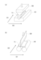
- FIGS. 1A and 1B are schematic diagrams showing the preparation of samples for U-bending and close bending tests in the examples, in which Fig. 1A shows U-bending (primary bending) and Fig. 1B shows bending (secondary bending).
- 2A and 2B are schematic diagrams showing the preparation of samples for V-bending and orthogonal VDA bending tests in the examples, in which Fig. 2A shows V-bending (primary bending) and Fig. 2B shows orthogonal VDA bending (secondary bending).
- 3(a) is a front view of a test member
- FIG. 3(b) is a front view of a test member
- FIG. 3(c) is a schematic diagram showing an axial crush test.
- C is one of the important basic components of steel, and in the present invention, it is an important element that affects the area ratios of martensite, ferrite, and retained austenite.
- the C content exceeds 0.500%, the martensite becomes embrittled and the amount of retained austenite increases, making it difficult to achieve the desired TS.
- the amount of martensite transformed from the retained austenite increases, which reduces the bendability.
- the increase in the retained austenite causes cracks to form on the sheared edge during shearing, which increases the length of the cracks after immersion in hydrochloric acid. Therefore, the C content is set to 0.030% or more and 0.500% or less.
- the C content is preferably set to 0.050% or more, It is more preferably 0.070% or more, and is also preferably 0.400% or less, more preferably 0.300% or less.
- Silicon is one of the important basic components of steel.
- silicon suppresses the formation of carbides during continuous annealing and promotes the formation of retained austenite, thereby improving the hardness of martensite and the area of the retained austenite. If the Si content is less than 0.01%, the tempering of martensite proceeds, making it difficult to achieve the desired TS. %, the segregation of Si becomes significant, so that the standard deviation of the Si concentration at the 1/2 position of the sheet thickness/the average Si concentration increases, and the damage degree of the sheared end surface in a corrosive environment increases.
- the Si content is set to 0.01% or more and 2.50% or less.
- the amount is preferably 0.05% or more, more preferably 0.10% or more, and is preferably 2.00% or less, more preferably 1.80% or less.
- Mn 0.10% or more and 5.00% or less
- Mn is one of the important basic components of steel, and in the present invention, it is an important element that affects the area ratio of martensite.
- the Mn content is less than 0.10%, the area ratio of martensite is
- the Mn content exceeds 5.00%, the segregation of Mn becomes significant, and as a result, the segregation of Si also becomes significant.
- the standard deviation/average Si concentration at the half-thickness position increases, and the damage level of the sheared edge in a corrosive environment increases.
- the amount of retained austenite increases, and the martensite that transforms from the retained austenite increases.
- the amount of Mn increases, and the bendability decreases.
- the Mn content is set to 0.10% or more and 5.00% or less.
- the Mn content is preferably 0.80% or more, and more preferably 0.80% or more. is 1.00% or more, and is preferably 4.50% or less, and more preferably 4.00% or less.
- P is an element that segregates at prior austenite grain boundaries, embrittling the grain boundaries and reducing the ultimate deformability of the steel sheet, and may also reduce the bendability. Therefore, the P content is set to 0.100% or less.
- the lower limit of the P content is not particularly limited, but since P is a solid solution strengthening element and can increase the strength of the steel sheet, it is preferably 0.001% or more. is preferred.
- S 0.0200% or less
- S exists as sulfide and is an element that reduces the ultimate deformability of the steel sheet, which can reduce the bendability. Therefore, the S content is set to 0.0200% or less, and preferably 0.0050% or less. Although there is no particular lower limit for the S content, it is preferably 0.0001% or more due to restrictions on production technology.
- Al is an element that increases the A3 transformation point, and the amount of ferrite in the steel structure increases, which may make it difficult to achieve the desired YR. Therefore, the Al content is set to 1.000% or less, and preferably The lower limit of the Al content is not particularly limited, but it is preferably 0.001% or more because it suppresses the formation of carbides during continuous annealing and promotes the formation of retained austenite. preferable.
- N 0.0100% or less
- N exists as a nitride and is an element that reduces the ultimate deformability of the steel sheet, which can reduce the bendability. Therefore, the N content is set to 0.0100% or less, and preferably 0.0050% or less. Although there is no particular lower limit for the N content, due to restrictions on production technology, the N content is preferably 0.0001% or more.
- O exists as an oxide and is an element that reduces the ultimate deformability of the steel sheet, which can reduce the bendability. Therefore, the O content is set to 0.0100% or less, and preferably 0.0050% or less. Although there is no particular lower limit for the O content, due to restrictions on production technology, the O content is preferably 0.0001% or more.
- the high strength steel plate of the present invention further comprises, in addition to the above-mentioned composition, in mass%: Ti: 0.200% or less, Nb: 0.200% or less, V: 0.200% or less, Ta: 0.10% or less, W: 0.10% or less, B: 0.0100% or less, Cr: 1.00% or less, Mo: 1.00% or less, Ni: 1.00% or less, Co: 0.010% or less, Cu: 1.00% or less, Sn: 0.200% or less, Sb: 0.200% or less, Ca: 0.0100% or less, Mg: 0.0100% or less, REM: 0.0100% or less, Zr: 0.020% or less, Te: 0.020% or less, At least one element selected from the group consisting of Hf: 0.10% or less and Bi: 0.200% or less may be contained. These elements may be contained alone or in combination of two or more kinds.
- the Ti, Nb or V content is preferably 0.200% or less, and more preferably 0.100% or less.
- the Ti, Nb or V content is preferably 0.001% or more.
- the Ta or W content is preferably 0.10% or less, and more preferably 0.08% or less.
- the Ta or W content is preferably 0.01% or more, respectively.
- the B content is preferably 0.0100% or less, and more preferably 0.0080% or less.
- the B content is preferably 0.0003% or more.
- the Cr, Mo or Ni content is 1.00% or less, and more preferably 0.80% or less.
- the Cr, Mo or Ni content is 0.01% or more.
- the Co content is preferably 0.010% or less, and more preferably 0.008% or less, in order to avoid an increase in coarse precipitates and inclusions, which reduces the ultimate deformability of the steel sheet and ultimately reduces its bendability.
- the Co content is 0.001% or more.
- the Cu content is preferably 1.00% or less, and more preferably 0.80% or less. There is no particular lower limit for the Cu content, but since Cu is an element that improves hardenability, it is preferable that the Cu content be 0.01% or more.
- the Sn content is preferably 0.200% or less, and more preferably 0.100% or less. There is no particular lower limit for the Sn content, but since Sn is an element that improves hardenability, it is preferable that the Sn content be 0.001% or more.
- the Sb content is preferably 0.200% or less, and more preferably 0.100% or less. There is no particular lower limit for the Sb content, but since Sb is an element that controls the surface softening thickness and enables strength adjustment, it is preferable that the Sb content be 0.001% or more.
- the Ca, Mg or REM content is 0.0100% or less, and more preferably 0.0050% or less.
- the Ca, Mg or REM content is 0.0005% or more.
- the Zr or Te content is preferably 0.100% or less, and more preferably 0.080% or less.
- the Zr or Te content is 0.001% or more.
- the Hf content is preferably 0.10% or less, and more preferably 0.08% or less.
- the Hf content is preferably 0.01% or more.
- the Bi content is preferably 0.200% or less, and more preferably 0.100% or less.
- the Bi content is 0.001% or more.
- the high-strength steel plate of the present invention has a composition that contains essential components and, in some cases, optional components, with the balance being Fe and unavoidable impurities.
- unavoidable impurities include Zn, Pb, As, Ge, Sr, and Cs. These unavoidable impurities are permitted to be contained in a total amount of 0.100% or less.
- the area ratio of martensite is set to 40% or more.
- the area ratio of martensite is preferably 55% or more, more preferably 60% or more, and even more preferably 80% or more. There is no particular upper limit to the area ratio of martensite, and the desired characteristics can be obtained even if it is 100%.
- the martensite referred to here includes tempered martensite and bainite in addition to quenched martensite (fresh martensite).
- the observation position for the area ratio of martensite is a quarter position of the sheet thickness of the steel sheet, as described later.
- the area ratio of ferrite is set to 70% or less.
- the area ratio of ferrite is preferably 50% or less, more preferably 40% or less, and further preferably 30% or less. There is no particular lower limit for the area ratio of ferrite, and the desired characteristics can be obtained even if it is 0%.
- the ferrite referred to here includes bainitic ferrite. Note that the observation position for the area ratio of ferrite is a quarter position of the sheet thickness of the steel sheet, as described later.
- the method for measuring the area ratios of martensite (quenched martensite, tempered martensite, and bainite) and ferrite (bainitic ferrite) is as follows.
- a sample is cut out from the steel sheet so that the plate thickness cross section (L cross section) parallel to the rolling direction becomes the observation surface.
- the observation surface of the sample is mirror-polished with diamond paste, then finish-polished with alumina, and further etched with 3 volume % nital to reveal the structure.
- the sample is observed at the latter 1/4 position of the plate thickness at a magnification of 3000 times using a scanning electron microscope (SEM) under conditions of an acceleration voltage of 10 kV, and SEM images of three fields of view (one field of view is 40 ⁇ m ⁇ 30 ⁇ m) are obtained.
- SEM scanning electron microscope
- the area ratio of each structure ferrite (bainitic ferrite), martensite (quenched martensite, tempered martensite, and bainite)
- Adobe Photoshop manufactured by Adobe Systems. Specifically, the area ratio of each structure is determined by dividing the area of each structure by the measured area. The area ratio of each structure is calculated for three fields of view, and the average value of these is determined as the area ratio of each structure.
- ferrite (bainitic ferrite) is a concave structure that is flat and does not contain carbides
- tempered martensite and bainite are concave structures that contain fine carbides
- quenched martensite is a convex structure with fine irregularities inside, and they are distinguishable from each other. Note that tempered martensite and bainite do not need to be distinguishable from each other, since the total area ratio is calculated as the area ratio of martensite.
- the steel structure of a steel plate is usually roughly symmetrical from top to bottom in the plate thickness direction, so any one of the surfaces (front and back) of the steel plate can be used as a representative for identifying the structure and measuring the volume fraction of retained austenite and the thickness of the soft surface layer, which will be described later.
- any one of the surfaces (front and back) of the steel plate can be used as the starting point of the plate thickness position (plate thickness 0 position), such as the 1/4 plate thickness position. The same applies below.
- volume fraction of retained austenite 20.0% or less
- the volume fraction of the retained austenite is set to 20.0% or less.
- the volume fraction of the retained austenite is preferably 15% or less, more preferably 10% or less, and even more preferably 5% or less. There is no particular lower limit to the volume fraction of the retained austenite, and the desired characteristics can be obtained even if it is 0%.
- the volume fraction of retained austenite was observed at a position corresponding to 1/4 of the sheet thickness of the steel sheet, and the measurement method was as follows. First, the steel plate is ground so that the measurement surface is at 1/4 of the plate thickness (a position corresponding to 1/4 of the plate thickness in the depth direction from the surface of the steel plate), and then the steel plate is further polished by 0.1 mm by chemical polishing to obtain a sample. For the measurement surface of the sample, an X-ray diffractometer is used to measure the integrated reflection intensities of the (200), (220), and (311) planes of fcc iron (austenite), and the (200), (211), and (220) planes of bcc iron, using a Co K ⁇ radiation source. The intensity ratio of the integrated reflection intensity of each surface of the fcc iron to the integrated reflection intensity of each surface of the bcc iron is calculated, and the average value of the nine intensity ratios is taken as the volume fraction of retained austenite.
- the steel structure of the present invention may have a structure (remaining structure) other than the above-mentioned martensite, ferrite, and retained austenite.
- the remaining structure is a structure other than martensite, ferrite, and retained austenite, and includes structures known as structures of steel sheets, such as pearlite, cementite, and carbides such as metastable carbides (epsilon ( ⁇ ) carbide, eta ( ⁇ ) carbide, chi ( ⁇ ) carbide, etc.).
- the remaining structure can be identified by, for example, observation with a SEM.
- the area ratio of the remaining structure at the 1/4 position of the sheet thickness of the steel sheet is preferably 5% or less, and may be 0%.
- [1-3] Standard deviation of Si concentration at 1/2 thickness position/average Si concentration The value of the ratio of the standard deviation of Si concentration to the average value of Si concentration (standard deviation of Si concentration/average Si concentration) is an extremely important configuration in the present invention, and by reducing the standard deviation of Si concentration/average Si concentration, in other words, by suppressing the segregation of Si, the degree of damage to the sheared end surface in a corrosive environment can be reduced.
- the standard deviation of Si concentration/average Si concentration at the 1/2 thickness position is set to 1.00 or less, preferably 0.80% or less, more preferably 0.60% or less, and even more preferably 0.50% or less.
- the lower limit of the standard deviation of Si concentration/average Si concentration at the 1/2 thickness position is not particularly limited, and even if it is 0, the desired characteristics can be obtained.
- the method for measuring the standard deviation of the Si concentration/average Si concentration at the 1/2 sheet thickness position is as follows.
- a sample is cut out from the steel sheet so that the plate thickness cross section (L cross section) parallel to the rolling direction becomes the observation surface.
- the observation surface of the sample is polished.
- the observation surface of the sample is mirror-polished using diamond paste, and then finish-polished using alumina.
- the center position of the thickness of the steel plate is set as the observation position (i.e., the center position of the thickness of the steel plate (1/2 thickness position) is set as the center position of the measurement area in the thickness direction), and the Si concentration is measured under the conditions of acceleration voltage: 15 kV, measurement area: 500 ⁇ m ⁇ 800 ⁇ m, beam diameter 2.0 ⁇ m, and number of measurement points: 250 ⁇ 400 (grid shape with measurement intervals of 2 ⁇ m), and the standard deviation / average Si concentration of the Si concentration at the 1/2 thickness position is calculated.
- the average value of the values calculated in the three areas is taken as the standard deviation / average Si concentration of the Si concentration at the 1/2 thickness position.
- the plate thickness of the high strength steel plate of the present invention is not particularly limited, but is usually 0.3 mm or more and 2.8 mm or less.
- the surface layer of the high-strength steel sheet of the present invention is preferably a soft layer (soft surface layer).
- the soft surface layer contributes to suppressing the propagation of bending cracks during press forming and vehicle body collision, thereby achieving further improvement in bendability.
- the surface layer refers to a region corresponding to a thickness of 200 ⁇ m from the surface of the high strength steel plate to 200 ⁇ m in the plate thickness direction.
- the high-strength steel sheet is a high-strength steel sheet that has been subjected to plating treatment such as a hot-dip galvanized steel sheet, a galvannealed steel sheet, an electrolytic galvanized steel sheet, or a metal-plated steel sheet
- the surface layer of the high-strength steel sheet refers to a region corresponding to a thickness of 200 ⁇ m from the surface of the steel sheet, which is the base (substrate) for various platings, to 200 ⁇ m in the sheet thickness direction.
- the soft layer refers to a region having a Vickers hardness of 85% or less of the Vickers hardness of a cross section (a plane parallel to the steel plate surface) at 1/4 of the plate thickness of the high-strength steel plate.
- the soft layer includes a decarburized layer in the surface layer of the high-strength steel plate.
- the surface soft layer refers to a soft layer included in the surface layer, and may be a soft layer in its entirety or a part of it.
- the surface soft layer may be a region corresponding to a thickness of 200 ⁇ m or less from the surface of the high-strength steel plate in the plate thickness direction.
- a region having a Vickers hardness of 85% or less on a cross section (plane parallel to the steel plate surface) at 1/4 of the plate thickness of a high-strength steel plate is formed at a predetermined depth from the surface of the high-strength steel plate in the plate thickness direction, when the predetermined depth is within 200 ⁇ m in the plate thickness direction, the region corresponding to the thickness from the surface to the predetermined depth in the plate thickness direction is the soft surface layer, and when the predetermined depth exceeds 200 ⁇ m in the plate thickness direction, the region corresponding to a thickness of 200 ⁇ m from the surface of the high-strength steel plate to a depth of 200 ⁇ m in the plate thickness direction is the soft surface layer.
- the thickness of the soft surface layer is preferably 10 ⁇ m or more, more preferably 12 ⁇ m or more, and even more preferably 15 ⁇ m or more. In order to avoid a decrease in TS, the thickness of the soft surface layer is preferably 150 ⁇ m or less, more preferably 100 ⁇ m or less, and even more preferably 80 ⁇ m or less.
- the thickness of the surface soft layer can be measured by the following method. After smoothing the thickness cross section (L cross section) of the base steel plate parallel to the rolling direction by wet polishing, measurements were taken at 1 ⁇ m intervals using a Vickers hardness tester with a load of 10 gf from a position 1 ⁇ m in the thickness direction from the surface of the base steel plate to a position 100 ⁇ m in the thickness direction. After that, measurements were taken at 20 ⁇ m intervals up to the center of the thickness. The area where the hardness was reduced to 85% or less compared to the hardness at the 1/4 position in the thickness direction was defined as the soft layer (surface soft layer), and the thickness in the thickness direction of this area was taken as the thickness of the soft layer.
- the proportion of nanohardness of 7.0 GPa or more is 0.10 or less.
- the proportion of nanohardness of 7.0 GPa or more is 0.10 or less, it means that the proportion of hard structures (martensite, etc.), inclusions, etc.
- the standard deviation ⁇ of the nanohardness of the sheet surface at a position 1/4 of the sheet thickness direction depth of the soft surface layer from the surface of the high-strength steel sheet is 1.8 GPa or less, and further, the standard deviation ⁇ of the nanohardness of the sheet surface at a position 1/2 of the sheet thickness direction depth of the soft surface layer from the surface of the high-strength steel sheet is 2.2 GPa or less.
- the standard deviation ⁇ of the nanohardness of the sheet surface at a position 1/4 of the sheet thickness direction depth of the soft surface layer from the surface of the high-strength steel sheet is 1.8 GPa or less
- the standard deviation ⁇ of the nanohardness of the sheet surface at a position 1/2 of the sheet thickness direction depth of the soft surface layer from the surface of the high-strength steel sheet is 2.2 GPa or less
- a more preferred range for the standard deviation ⁇ of the nanohardness of the plate surface at a position 1/4 of the way from the high-strength steel plate surface to the soft surface layer in the plate thickness direction is 1.7 GPa or less.
- a more preferred range for the standard deviation ⁇ of the nanohardness of the plate surface at a position 1/2 of the way from the high-strength steel plate surface to the soft surface layer in the plate thickness direction is 2.1 GPa or less.
- the nano-hardness of the plate surface at the 1/4 and 1/2 positions in the plate thickness direction depth is a hardness measured by the following method. First, if a plating layer is formed, the plating layer is peeled off, and then the nano hardness is measured from the surface of the high-strength steel sheet to a position 1/4 of the depth in the sheet thickness direction of the soft surface layer using a Berkovich-shaped diamond indenter under the following conditions: load: 500 ⁇ N, measurement area: 50 ⁇ m ⁇ 50 ⁇ m, and impact spacing: 2 ⁇ m.
- the soft surface layer is mechanically polished to a position halfway down the thickness direction, buffed with diamond and alumina, and then polished with colloidal silica.Then, the nano-hardness is measured with a Berkovich diamond indenter under the following conditions: load: 500 ⁇ N, measurement area: 50 ⁇ m ⁇ 50 ⁇ m, and impact spacing: 2 ⁇ m.
- the high-strength steel sheet of the present invention may have a plating layer on the surface.
- the high-strength steel sheet of the present invention preferably has a first plating layer, which is a metal plating layer, on one or both surfaces of the base steel sheet.
- the first plating layer is formed directly on the surface of the base steel sheet and is a metal plating layer containing more than 50 mass% in total of one or more selected from Cr, Mn, Fe, Co, Ni, Cu, Ga, Ge, As, Ru, Rh, Pd, Ag, Cd, In, Sn, Sb, Os, Ir, Rt, Au, Hg, Ti, Pb and Bi, and is not a hot-dip galvanized layer, an alloyed hot-dip galvanized layer, a zinc plating layer of an electrogalvanized layer, or a hot-dip aluminum plating layer.
- the first plating layer is preferably a metal electroplated layer, and the following description will be given taking a metal electroplated layer as an example.
- the outermost metal electroplating layer helps to prevent bending cracks during press forming and vehicle collisions, further improving bending fracture resistance.
- the metal type of the metal electroplating layer may be any of Cr, Mn, Fe, Co, Ni, Cu, Ga, Ge, As, Ru, Rh, Pd, Ag, Cd, In, Sn, Sb, Os, Ir, Rt, Au, Hg, Ti, Pb, and Bi, but Fe is more preferable.
- the deposition weight of the Fe-based electroplating layer is more than 0 g/ m2 , and preferably 2.0 g/ m2 or more. There is no particular upper limit to the deposition weight of the Fe-based electroplating layer per side, but from the viewpoint of cost, it is preferable that the deposition weight of the Fe-based electroplating layer per side is 60 g/m2 or less .
- the deposition weight of the Fe-based electroplating layer is preferably 50 g/ m2 or less, more preferably 40 g/m2 or less, and even more preferably 30 g/m2 or less.
- the adhesion weight of the Fe-based electroplating layer is measured as follows. A 10 x 15 mm sample is taken from the Fe-based electroplated steel sheet and embedded in resin to create a cross-section embedded sample. Three random locations on the cross section are observed using a scanning electron microscope (SEM) at an accelerating voltage of 15 kV and a magnification of 2,000 to 10,000 times depending on the thickness of the Fe-based plating layer, and the average thickness of the three fields of view is multiplied by the specific gravity of iron to convert it into the adhesion weight of the Fe-based plating layer per side.
- SEM scanning electron microscope
- the Fe-based electroplating layer in addition to pure Fe, alloy plating layers such as Fe-B alloy, Fe-C alloy, Fe-P alloy, Fe-N alloy, Fe-O alloy, Fe-Ni alloy, Fe-Mn alloy, Fe-Mo alloy, and Fe-W alloy can be used.
- the composition of the Fe-based electroplating layer is not particularly limited, but it is preferable that the composition contains one or more elements selected from the group consisting of B, C, P, N, O, Ni, Mn, Mo, Zn, W, Pb, Sn, Cr, V, and Co in a total amount of 10 mass% or less, with the remainder consisting of Fe and unavoidable impurities.
- the C content is preferably 0.08 mass% or less.
- the high-strength steel sheet according to one embodiment of the present invention may have a second plating layer, which is a metal plating layer, as an outermost layer on one or both sides of the high-strength steel sheet.
- the second plating layer contains at least one of zinc and aluminum in a total amount of 50 mass % or more, and may be a hot-dip galvanized layer, a galvannealed layer, an electrolytic galvanized layer, a hot-dip aluminum plating layer, or the like.
- the second plating layer may be formed directly on one or both surfaces of the base steel sheet surface, or it may be formed on the first plating layer.
- the hot-dip galvanized layer, alloyed hot-dip galvanized layer, and electrolytic galvanized layer refer to a plating layer containing Zn (zinc) as a main component (Zn content of 50.0 mass % or more).
- the plating layer of an aluminum-plated steel sheet refers to a plating layer containing Al (aluminum) as a main component (Al content is 50.0 mass % or more).
- the hot-dip galvanized layer is preferably composed of, for example, Zn, 20.0 mass% or less Fe, and 0.001 mass% or more and 1.0 mass% or less Al.
- the hot-dip galvanized layer may optionally contain one or more elements selected from the group consisting of Pb, Sb, Si, Sn, Mg, Mn, Ni, Cr, Co, Ca, Cu, Li, Ti, Be, Bi, and REM in a total amount of more than 0.0 mass% and 3.5 mass% or less.
- the Fe content of the hot-dip galvanized layer is more preferably less than 7.0 mass%. The remainder other than the above elements is unavoidable impurities.
- the galvannealed layer is preferably composed of, for example, 20% by mass or less Fe and 0.001% by mass or more and 1.0% by mass or less Al.
- the galvannealed layer may optionally contain one or more elements selected from the group consisting of Pb, Sb, Si, Sn, Mg, Mn, Ni, Cr, Co, Ca, Cu, Li, Ti, Be, Bi and REM in a total amount of more than 0% by mass and 3.5% by mass or less.
- the Fe content of the galvannealed layer is more preferably 7.0% by mass or more, and more preferably 8.0% by mass or more.
- the Fe content of the galvannealed layer is more preferably 15.0% by mass or less, and more preferably 12.0% by mass or less. The remainder other than the above elements is unavoidable impurities.
- the plating weight of the zinc plating layer per side is not particularly limited, but is preferably 20 g/m 2 or more and 80 g/m 2 or less.
- the coating weight of the zinc plating layer is measured as follows.
- a treatment solution is prepared by adding 0.6 g of a corrosion inhibitor for Fe (Ivit 700BK (registered trademark) manufactured by Asahi Chemical Industry Co., Ltd.) to 1 L of a 10 mass % aqueous hydrochloric acid solution.
- a sample of a steel sheet having a zinc plating layer is then immersed in the treatment solution to dissolve the zinc plating layer.
- the mass loss of the ampoule S before and after dissolution is then measured, and the value is divided by the surface area of the base steel sheet (the surface area of the part that was covered with plating) to calculate the coating weight (g/ m2 ).
- the method for producing a high strength steel plate of the present invention includes the steps of: casting molten steel having the above-mentioned composition, and then cooling the molten steel at an average cooling rate of 3.0°C/hr or more in a temperature range of 500°C or more and 700°C or less, and at an average cooling rate of 1.0°C/hr or more in a temperature range of 400°C or more and less than 500°C, to obtain a steel slab; a step of heating the steel slab to a slab heating temperature T1 of 1150°C or more, and then subjecting the steel slab to hot rolling with a coiling temperature of 600°C or less and a residence time in a temperature range of 300°C to 400°C in cooling after coiling of 50,000 s or less to obtain a hot-rolled sheet, wherein the residence time in a temperature range of 1100°C to T1 in heating the steel slab is 20 minutes or more; A step of subjecting the hot-rolled sheet to pickling; A step of cold rolling the pickled hot-
- the manufacturing method of the present invention includes a process of melting a steel material having a component composition of a high-strength steel plate to produce a steel slab (slab).
- the method of melting the steel material is not particularly limited, and any known melting method such as a converter or an electric furnace is suitable.
- the steel slab is preferably manufactured by a continuous casting method to prevent macrosegregation, but it can also be manufactured by an ingot casting method or a thin slab casting method.
- the steel material is melted, it is cooled at an average cooling rate of 3.0°C/hr or more in the temperature range of 500°C to 700°C, and at an average cooling rate of 1.0°C/hr or more in the temperature range of 400°C to less than 500°C.
- the average cooling rate in the temperature range of 500° C. to 700° C. is 3°C/hr or more, and by adopting this condition, the slab structure can be mainly a low-temperature transformation phase. As a result, local concentration of Si is reduced during the slab heating in the next process, and segregation of Si can be suppressed.
- the average cooling rate in the temperature range of 500°C to 700°C is 3.0°C/hr or more, preferably 5.0°C/hr or more.
- the upper limit of the average cooling rate in the temperature range of 500°C to 700°C is not particularly limited, but it is preferably 100.0°C/hr or less in order to control the thickness of the surface soft layer after annealing to an appropriate range and obtain a suitable TS.
- the temperature of the slab is the temperature of the surface of the slab.
- the average cooling rate in the temperature range of 400° C. or more and less than 500° C. is 1°C/hr or more, and by adopting this condition, the slab structure can be mainly a low-temperature transformation phase. As a result, local concentration of Si is reduced during the heating of the steel slab in the next process, and segregation of Si can be suppressed.
- the average cooling rate in the temperature range of 400°C or more and less than 500°C is set to 1.0°C/hr or more, preferably 3.0°C/hr or more.
- the upper limit of the average cooling rate in the temperature range of 400°C or more and less than 500°C is not particularly limited, but it is preferably 80.0°C/hr or less in order to control the thickness of the surface soft layer after annealing to an appropriate range and obtain a suitable TS.
- the temperature of the slab is the temperature of the surface of the slab.
- the steel slab is heated to a slab heating temperature T1 of 1150°C or more. At that time, the residence time in the temperature range of 1100°C or more and the slab heating temperature T1 or less is set to 20 minutes or more.
- the steel slab to be heated may be the steel slab obtained in the above process that has been cooled to room temperature once, or an energy-saving process such as direct rolling in which the hot slab is charged into a heating furnace without being cooled to room temperature may be applied.
- slab heating temperature T1 1150°C or higher
- the slab heating temperature T1 is set to 1150°C or higher, and preferably 1180°C or higher.
- the slab heating temperature T1 is preferably 1300°C or lower.
- the slab heating temperature is the temperature of the slab surface.
- the residence time is the temperature of the slab surface.
- the slab is then hot rolled, which may consist of rough rolling and finish rolling.
- the slab can be rough-rolled into a sheet bar.
- the conditions for the rough rolling are not particularly limited and may be any known conditions.
- the sheet bar can then be subjected to finish rolling, and may be heated using a bar heater or the like before the finish rolling.
- the finish rolling temperature is preferably the Ar3 transformation point or higher. If the temperature is the Ar3 transformation point or higher, it is possible to avoid an increase in the rolling load and an increase in the reduction ratio in the non-recrystallized state of austenite, and thus it is possible to suppress the development of an abnormal structure elongated in the rolling direction, and to easily avoid a decrease in the workability of the steel sheet obtained after annealing.
- the Ar3 transformation point is calculated by the following formula.
- Ar 3 (°C) 868-396 ⁇ [%C]+24.6 ⁇ [%Si]-68.1 ⁇ [%Mn]-36.1 ⁇ [%Ni]-20.7 ⁇ [%Cu]-24.8 ⁇ [%Cr]
- the symbol [% element symbol] represents the content (mass %) of the corresponding element in the composition.
- Finish rolling may be performed continuously by joining sheet bars together. Also, the sheet bars may be wound up once before finish rolling. Furthermore, in order to reduce the rolling load, part or all of the finish rolling may be performed as lubricated rolling. Performing lubricated rolling is also effective from the viewpoint of uniformity of the steel sheet shape and material quality.
- the friction coefficient during lubricated rolling is preferably in the range of 0.10 to 0.25.
- the manufacturing method of the present invention it is particularly important to control the coiling temperature in the hot rolling process and the residence time in the temperature range of 300°C to 400°C during cooling after coiling.
- the hot rolled sheet is coiled and collected, and then cooled.
- the coiling temperature is set to 600°C or less, so that the hot rolled structure is mainly a low-temperature transformation phase.
- the coiling temperature is set to 600° C. or less, and preferably 550° C. or less.
- the winding temperature is preferably 300° C. or higher since it is necessary to control the residence time in a temperature range of 300° C. or higher and 400° C. or lower during cooling after winding.
- dwell time in the temperature range of 300° C. to 400° C. during cooling after winding (hereinafter, dwell time in the temperature range of 300° C. to 400° C.): 50,000 s or less]
- dwell time in the temperature range of 300° C. to 400° C. 50,000 s or less.
- the hot-rolled structure is mainly a low-temperature transformation phase.
- the retention time in the temperature range of 300° C. to 400° C. is set to 50,000 s or less, preferably 30,000 s or less.
- the lower limit of the retention time in the temperature range of 300° C. to 400° C. is not particularly limited, and the desired characteristics can be obtained even if it is, for example, 2000 s.
- the cooling conditions after retention in the temperature range of 300°C to 400°C are not particularly limited, and known conditions can be used.
- the cooling rate is preferably 0.001°C/s to 1°C/s
- the cooling stop temperature is preferably 20°C to 200°C.
- Pickling can remove oxides from the steel sheet surface, ensuring good chemical conversion treatment properties and plating quality. Pickling may be performed once or multiple times.
- the pickling conditions are not particularly limited, and known conditions can be applied.
- the hot-rolled sheet may be subjected to a heat treatment (hot-rolled sheet annealing).
- the heat treatment conditions are not particularly limited, and known conditions can be applied.
- cold rolling process Next, the hot rolled sheet is cold rolled to obtain a cold rolled sheet.
- the cold rolling conditions are not particularly limited, and known conditions can be applied.
- cold rolling can be performed by two or more passes using tandem multi-stand rolling or reverse rolling.
- the cumulative reduction in cold rolling is preferably, for example, 20% to 75%.
- the number of passes and the reduction in each pass are not particularly limited, and known conditions can be applied.
- a first plating step may be included in which a first plating layer, which is a metal plating layer, is formed on one or both sides of the steel sheet after the hot rolling step (after the cold rolling step if cold rolling is performed) and before the annealing step.
- the first plating step is preferably a metal electroplating treatment step.
- a metal plating process such as metal electroplating may be applied to the surface of the cold-rolled sheet obtained as described above to produce a pre-annealed metal-plated steel sheet having a pre-annealed metal plating layer formed on at least one side.
- the metal plating layer referred to here may be the above-mentioned first plating layer.
- the pre-annealed metal-plated steel sheet is preferably a pre-annealed metal electroplated steel sheet provided with a pre-annealed metal electroplating layer.
- the metal electroplating method is not particularly limited, but as described above, it is preferable to form a metal electroplating layer on the base steel sheet, and therefore it is preferable to perform a metal electroplating process.
- a sulfuric acid bath, a hydrochloric acid bath, or a mixture of both can be used for an Fe-based electroplating bath.
- the amount of adhesion of the metal electroplating layer before annealing can be adjusted by the current application time, etc.
- the metal electroplated steel sheet before annealing means that the metal electroplating layer has not been subjected to an annealing process, and does not exclude the case where the hot-rolled sheet before the metal electroplating process, the pickled sheet after hot rolling, or the cold-rolled sheet has been annealed in advance.
- the metal species of the electroplating layer can be any of Cr, Mn, Fe, Co, Ni, Cu, Ga, Ge, As, Ru, Rh, Pd, Ag, Cd, In, Sn, Sb, Os, Ir, Rt, Au, Hg, Ti, Pb, and Bi, but since Fe is more preferable, the manufacturing method of Fe-based electroplating is described below.
- the Fe ion content in the Fe-based electroplating bath before the start of energization is preferably 0.5 mol/L or more in terms of Fe 2+ . If the Fe ion content in the Fe-based electroplating bath is 0.5 mol/L or more in terms of Fe 2+ , a sufficient Fe deposition amount can be obtained. In addition, in order to obtain a sufficient Fe deposition amount, the Fe ion content in the Fe-based electroplating bath before the start of energization is preferably 2.0 mol/L or less.
- the Fe-based electroplating bath may contain at least one element selected from the group consisting of B, C, P, N, O, Ni, Mn, Mo, Zn, W, Pb, Sn, Cr, V and Co in addition to Fe ions.
- the total content of these elements in the Fe-based electroplating bath is preferably such that the total content of these elements in the Fe-based electroplating layer before annealing is 10 mass% or less.
- the metal elements may be contained as metal ions, and the nonmetal elements may be contained as part of boric acid, phosphoric acid, nitric acid, organic acid, etc.
- the iron sulfate plating solution may also contain a conductivity aid such as sodium sulfate or potassium sulfate, a chelating agent, or a pH buffer.
- the temperature of the Fe-based electroplating solution is preferably 30° C. or higher from the viewpoint of constant temperature retention, and is preferably 85° C. or lower.
- the pH of the Fe-based electroplating bath is not particularly limited, but is preferably 1.0 or higher from the viewpoint of preventing a decrease in current efficiency due to hydrogen generation, and is preferably 3.0 or lower from the viewpoint of the electrical conductivity of the Fe-based electroplating bath.
- the current density is preferably 10 A/dm 2 or higher from the viewpoint of productivity, and is preferably 150 A/dm 2 or lower from the viewpoint of facilitating control of the deposition amount of the Fe-based electroplating layer.
- the sheet passing speed is preferably 5 mpm or higher from the viewpoint of productivity, and is preferably 150 mpm or lower from the viewpoint of stably controlling the deposition amount.
- a degreasing treatment and water washing for cleaning the surface of the cold-rolled sheet, and further, a pickling treatment and water washing for activating the surface of the cold-rolled sheet can be performed.
- the Fe-based electroplating treatment is performed following these pretreatments.
- the method of the degreasing treatment and water washing is not particularly limited, and a conventional method can be used.
- various acids such as sulfuric acid, hydrochloric acid, nitric acid, and mixtures thereof can be used. Among them, sulfuric acid, hydrochloric acid, and mixtures thereof are preferred.
- the concentration of the acid is not particularly limited, but is preferably 1% by mass or more and 20% by mass or less from the viewpoints of the ability to remove the oxide film and the prevention of roughness (surface defects) due to over-pickling.
- the pickling treatment solution may also contain an antifoaming agent, a pickling promoter, a pickling inhibitor, and the like.
- Annealing step The cold-rolled sheet obtained as described above or the cold-rolled sheet after the first plating step is annealed.
- the cold-rolled sheet may be metal-plated or may not be metal-plated. During annealing, it is important to satisfy the following conditions.
- the average heating rate in the temperature range of 250° C. to 700° C. is 10° C./s or more, preferably 12° C./s or more, and more preferably 14° C./s or more.
- the upper limit of the average heating rate in the temperature range of 250° C. to 700° C. is preferably 50° C./s or less, and more preferably 40° C./s or less.
- the residence time in the temperature range of 750°C or more and less than Ac 3 point is set to 200 seconds or less, preferably 150 seconds or less, and more preferably 120 seconds or less.
- the lower limit of the residence time in the temperature range of 750°C or more and less than Ac 3 point is not particularly limited, but in order to make the area ratio of martensite a suitable area ratio and to make TS more suitable, 10 seconds or more is preferable.
- Heating temperature T2 Ac 3 points or more
- the heating temperature T2 is Ac3 or higher, the annealing process is performed in the two-phase region of ferrite and austenite, so that a large amount of ferrite is contained after annealing, and the desired TS and bendability can be achieved.
- the heating temperature T2 is The heating temperature T2 is set to Ac 3 or higher, preferably (Ac 3 + 10°C) or higher, and more preferably (Ac 3 + 15°C) or higher.
- the upper limit of the heating temperature T2 is not particularly limited, but as the heating temperature T2 increases, Since there is a risk that the thickness of the soft surface layer after annealing increases and TS decreases, the annealing temperature is preferably 950°C or lower, and more preferably 920°C or lower.
- the heat retention time at the heating temperature (annealing temperature) T2 is not particularly limited, but is preferably 10 s or more and 600 s or less. Here, the heating temperature is measured based on the temperature of the steel sheet surface.
- the thickness of the soft surface layer after annealing increases and TS may decrease, so that the oxygen concentration in the temperature range of 250°C to 700°C is preferably 30 ppm by volume or less, more preferably 28 ppm by volume or less, and even more preferably 25 ppm by volume or less.
- the temperature range of 250° C. to 700° C. is based on the surface temperature of the steel sheet. That is, when the surface temperature of the steel sheet is in the above-mentioned temperature range of 250° C. to 700° C., the oxygen concentration is adjusted to be within the above-mentioned range.
- the dew point of atmosphere at heating temperature T2 is preferably set to ⁇ 35° C. or higher, more preferably ⁇ 30° C. or higher, and even more preferably ⁇ 25° C. or higher.
- the upper limit of the dew point at the heating temperature T2 is not particularly limited, but from the viewpoint of controlling the thickness of the soft surface layer after annealing to a suitable range and obtaining a more suitable TS, the dew point at the heating temperature T2 is preferably 15° C. or lower, more preferably 5° C. or lower.
- the heating temperature T2 is based on the surface temperature of the steel sheet. That is, when the surface temperature of the steel sheet is at the heating temperature T2 , the dew point is adjusted to fall within the above range.
- the average cooling rate at the heating temperature T2 or lower and exceeding 400° C. is not particularly limited, but is preferably 5° C./s or higher and 30° C./s or lower.
- the high-strength steel sheet may be cooled once and the steel sheet temperature may be increased again.
- Cooling step [average cooling rate in the temperature range of 250°C to 400°C: 1.0°C/s or more] If the average cooling rate in the temperature range of 250°C to 400°C is less than 1.0°C/s, a large amount of bainitic ferrite will be contained after annealing, making it difficult to achieve the desired TS, YR and bendability. Therefore, the average cooling rate in the temperature range of 250°C to 400°C is 1.0°C/s or more, preferably 2.0°C/s or more, and more preferably 3.0°C/s or more.
- the average cooling rate in the temperature range of 250°C to 400°C is preferably 1000°C/s or less, preferably 100.0°C/s or less, and more preferably 80.0°C/s or less.
- the average cooling rate is measured based on the temperature of the steel sheet surface.
- the cooling method in the temperature range of 250°C to 400°C is not particularly limited, and examples that can be used include gas jet cooling, mist cooling, water cooling, and air cooling.
- Heat retention temperature T3 in the cooling process 100°C or higher and 450°C or lower (preferred conditions)]
- the high-strength steel plate is subjected to heat retention, so that TS, YR and bendability can be kept within more suitable ranges.
- the heat retention temperature T3 in the cooling step is preferably 100°C or higher, more preferably 150°C or higher, and even more preferably 200°C or higher.
- the heat retention temperature T3 in the cooling step is preferably 450°C or lower, more preferably 400°C or lower, and even more preferably 350°C or lower.
- the temperature in the cooling process is based on the surface temperature of the steel sheet.
- the heat-keeping time at the heat-keeping temperature T3 in the cooling step is preferably 5 seconds or more, more preferably 10 seconds or more, and even more preferably 15 seconds or more.
- the upper limit of the heat-keeping time at the heat-keeping temperature T3 in the cooling step is not particularly limited, but in order to obtain a suitable TS, the heat-keeping time at the heat-keeping temperature T3 in the cooling step is preferably 500 seconds or less, and more preferably 250 seconds or less.
- the average cooling rate in the temperature range of 250°C or more and 400°C or less is the average cooling rate in the cooling excluding the heat retention process at the heat retention temperature T3 .
- the average cooling rate can be calculated from the average cooling rate from 250°C to T3 and the average cooling rate from T3 to 400°C.
- the cooling stop temperature T4 is set to 250°C or less. and preferably 200° C. or lower.
- the lower limit of the cooling stop temperature T4 is not particularly limited, but is preferably room temperature or higher from the viewpoint of productivity.
- the average stopping speed is measured based on the temperature of the steel sheet surface.
- the average cooling rate from 250° C. to the cooling end temperature T4 is not particularly limited, but in order to further increase TS, the average cooling rate in the temperature range of 250° C. or less to T4 is preferably 1° C./s or more, more preferably 2° C./s or more. On the other hand, due to constraints on production technology, the average cooling rate in the temperature range of 250° C. or less to T4 is preferably 1000° C./s or less, more preferably 150° C./s or less.
- the cold-rolled sheet may be cooled from the cooling stop temperature T4 to room temperature.
- the average cooling rate from the cooling stop temperature T4 to room temperature is not particularly limited, and the sheet can be cooled to room temperature by any method.
- As the cooling method gas jet cooling, mist cooling, water cooling, air cooling, etc. can be applied.
- the annealed cold-rolled sheet may be cooled to a cooling stop temperature T4 , and then rolled at an elongation rate of 0.05% or more and 2.00% or less.
- the YR can be controlled to a desired range.
- the elongation rate is more preferably 0.10% or more.
- the volume fraction of retained austenite can be set within a more suitable range, and the bendability and the damage degree of the sheared end surface in a corrosive environment can be set within a more suitable range.
- the elongation rate is more preferably 1.00% or less.
- the rolling after cooling to the cooling stop temperature T4 may be performed on an apparatus continuous with the above-mentioned continuous annealing apparatus (online) or on an apparatus not continuous with the above-mentioned continuous annealing apparatus (offline).
- the target elongation may be achieved by one rolling, or a total of 0.05% to 2.00% elongation may be achieved by multiple rolling.
- the rolling described here generally refers to temper rolling, but may be a processing method using repeated bending with a tension leveler or rolls, etc., as long as it can impart an elongation equivalent to that of temper rolling.
- Reheating step [Reheating temperature: (cooling stop temperature T 4 +50°C) or higher and 450°C or lower (preferred conditions)]
- the reheating temperature is preferably set to (cooling end temperature T4 + 50°C) or higher, more preferably (cooling end temperature T4 + 100°C) or higher, and even more preferably (cooling end temperature T 4 +150°C) or higher.
- the tempering of martensite progresses and TS decreases.
- the reheating temperature is preferably 450°C or lower, and more preferably 400°C or lower.
- the temperature is preferably 380° C. or lower, and more preferably 380° C. or lower.
- the temperature of the heating temperature range is based on the surface temperature of the steel sheet, that is, when the surface temperature of the steel sheet is within the heating temperature range, the oxygen concentration is adjusted to be within the above range.
- the heat-maintenance time at the reheating temperature is preferably 5 seconds or more, more preferably 10 seconds or more, and even more preferably 15 seconds or more.
- the upper limit of the heat-maintenance time at the reheating temperature is not particularly limited, but in order to keep TS within a more suitable range, the heat-maintenance time at the reheating temperature is more preferably 500 seconds or less, and even more preferably 250 seconds or less.
- the cooling rate from the reheating temperature to room temperature is not particularly limited, and any method can be used to cool to room temperature. Cooling methods that can be used include gas jet cooling, mist cooling, water cooling, and air cooling.
- Second plating process (optional)
- the high-strength steel sheet manufactured as described above can be subjected to a plating process to obtain a plated steel sheet.
- the plating process include a hot-dip galvanizing process and a process of alloying after hot-dip galvanizing. Annealing and galvanizing may be performed continuously in one line.
- a plating layer may be formed by electroplating such as Zn-Ni electric alloy plating, or hot-dip zinc-aluminum-magnesium alloy plating may be applied. Note that, although the above description has focused on the case of galvanizing, the type of plating metal such as Zn plating or Al plating is not particularly limited.
- hot-dip galvanizing it is preferable to immerse the steel sheet in a zinc plating bath at 440°C to 500°C, and then adjust the coating weight by gas wiping or the like.
- a plating bath with an Al content of 0.10 mass% to 0.23 mass%, with the balance consisting of Zn and unavoidable impurities.
- alloying galvanizing treatment after performing hot-dip galvanizing treatment as described above, it is preferable to perform alloying treatment by heating the steel sheet having a hot-dip galvanized layer (hot-dip galvanized steel sheet) to an alloying temperature of 450°C or more and 600°C or less. If the alloying temperature is less than 450°C, the Zn-Fe alloying rate slows down and alloying may become difficult. On the other hand, if the alloying temperature exceeds 600°C, untransformed austenite transforms to pearlite, making it difficult to achieve a TS of 590 MPa or more.
- the alloying temperature is more preferably 510°C or more. Also, the alloying temperature is more preferably 570°C or less.
- the coating weight of the steel sheet having a hot-dip galvanized layer (hot-dip galvanized steel sheet) (GI) and the steel sheet having a galvannealed layer (galvannealed hot-dip galvanized steel sheet) (GA) is preferably 20 to 80 g/ m2 per side.
- the coating weight can be adjusted by gas wiping or the like.
- the cold-rolled sheet obtained by annealing the cold-rolled sheet is immersed in an aluminum plating bath at 660 to 730°C to apply the molten aluminum plating process, and then the coating weight is adjusted by gas wiping, etc.
- the coating thickness be in the range of 2 ⁇ m to 15 ⁇ m.
- Skin pass rolling (optional) After the plating treatment, skin pass rolling may be carried out.
- the reduction ratio in the skin pass rolling is preferably 0.05% or more from the viewpoint of increasing the yield strength.
- the upper limit of the reduction ratio is not particularly limited, but is preferably 1.50% from the viewpoint of productivity.
- Skin pass rolling may be performed either online or offline. The skin pass may be performed at a single time to the desired rolling reduction, or may be performed in several steps.
- the member of the present invention is a member at least partially made of the high-strength steel plate of the present invention.
- the member of the present invention can be obtained, for example, by forming the high-strength steel plate of the present invention into a desired shape by press working or the like.
- the member of the present invention can be suitably used for automobile parts (for example, for automobile frame structural parts, automobile reinforcing parts, etc.).
- the present invention also relates to an automobile part made of the member of the present invention.
- the high-strength steel plate of the present invention has a high YR, high bendability, and enhanced corrosion resistance at the sheared end surface, and has a TS of 1180 MPa or more. Therefore, the member of the present invention can contribute to reducing the weight of the vehicle body, and can be suitably used for general members for automobile parts (for example, for automobile frame structural parts or automobile reinforcing parts).
- a zinc bath containing 0.14 to 0.19 mass% Al was used for GI, and a zinc bath containing 0.14 mass% Al was used for GA, with the bath temperature set to 470°C.
- the coating weight was about 45 to 72 g/ m2 per side (double-sided plating) for GI, and about 45 g/ m2 per side (double-sided plating) for GA.
- the Fe concentration in the plating layer for GA was set to 9 mass% or more and 12 mass% or less.
- the Ni content in the plating layer was set to 9 mass% or more and 25 mass% or less.
- the steel structure For the steel plates obtained in the above manner, the steel structure, the standard deviation of the Si concentration at 1/2 the plate thickness position/average Si concentration, and the thickness of the soft surface layer were measured.
- Step structure According to the above-mentioned method, the area ratio of martensite and ferrite and the volume ratio of retained austenite at the 1/4 position of the sheet thickness were obtained. The remaining structure was observed by the method described below. After cutting out a sample so that the sheet thickness cross section (L cross section) parallel to the rolling direction of the steel sheet was the observation surface, the observation surface was mirror-polished using diamond paste, and then finish-polished using colloidal silica, and further etched with 3% by volume of nital to reveal the structure.
- the bending test was performed in accordance with JIS Z 2248. From the obtained steel plate, a rectangular test piece with a width of 30 mm and a length of 100 mm was taken so that the axial direction of the bending test was parallel to the rolling direction of the steel plate. Then, a 90 ° V bending test was performed under the conditions of a pressing load of 100 kN and a pressing holding time of 5 seconds.
- the bendability was evaluated by the pass rate of the bending test, and a bending test was performed on five samples at the maximum R (for example, when the plate thickness is 1.2 mm, the bending radius is 6.0 mm) at which the value R / t obtained by dividing the bending radius (R) by the plate thickness (t) is 5 or less. Then, the presence or absence of cracks at the ridgeline of the bending apex was evaluated, and when none of the five samples were cracked, the bendability was judged to be "excellent”. In addition, when microcracks of less than 200 ⁇ m occurred in one or more of the five samples, the bendability was judged to be "good".
- the specimen was immersed in hydrochloric acid with a constant pH of 3 for 120 hours, and then removed and washed with running water.
- the rectangular test piece was removed from the four-point bending test fixture, and the rectangular test piece was cut parallel to the rolling direction so that the width center position of the specimen was the observation position.
- the cut surface of the test piece was mirror-polished, and the shear-split surface of the test piece was observed at a magnification of 1000 times using an SEM. The test piece was judged to be good when the crack on the shear-split surface of the test piece, that is, the crack length after immersion in hydrochloric acid was 300 ⁇ m or less.
- TS was 1180 MPa or more, and YR, bendability, and the degree of damage to the sheared end surface in a corrosive environment were excellent.
- YR, bendability, and the degree of damage to the sheared end surface in a corrosive environment were poor.
- Test No. 48-80 A steel having the composition shown in Table 1, with the balance being Fe and unavoidable impurities, was melted in a converter and formed into a slab by a continuous casting method. The obtained slab was heated, hot-rolled, pickled, and then cold-rolled.
- a metal electroplating process was performed on some of the cold-rolled steel sheets.
- the column for metal electroplating (plating type) in Table 4 cases where "Yes (Fe)” is written are examples where Fe-based electroplating was performed, and cases where "(Ni)” is written are examples where Ni-based electroplating was performed.
- the composition of the metal electroplating layer was 95 to 100 mass % Fe for the Fe-based electroplating, and 95 to 100 mass % Ni for the Ni-based electroplating, with the remainder being unavoidable impurities.
- the cold-rolled steel sheets were subjected to the types of plating treatments (GI, GA) shown in Table 4 to obtain plated steel sheets having hot-dip galvanized layers on both sides.
- the conditions for GI and GA were the same as above.
- composition of the base steel plate of the obtained steel plate was substantially the same as the composition of the steel slab stage, and all of the suitable steels were within the range of composition according to the embodiment described above.
- the steel structure For the steel sheets obtained in this manner, the steel structure, the standard deviation of the Si concentration at 1/2 the sheet thickness position, the average Si concentration, and the thickness of the soft surface layer were measured. In addition, the amount of metal plating layer attached was measured, and the nano-hardness of the soft surface layer was measured. The results are shown in Table 5.
- the surface soft layer was mechanically polished to a position halfway down the thickness direction, buffed with diamond and alumina, and polished with colloidal silica.
- Load 500 ⁇ N Measurement area: 50 ⁇ m x 50 ⁇ m
- Dot spacing 2 ⁇ m The nano-hardness was measured at a total of 512 points under the above conditions.
- the obtained steel plates were evaluated in the same manner as above for tensile properties, bendability, and damage to the sheared end surface in a corrosive environment. The results are shown in Table 5.
- the obtained steel sheets were subjected to U-bend + contact bending test, V-bend + orthogonal VDA bending test, and axial crushing test.
- the influence of the sheet thickness was taken into consideration, and all tests were performed with steel sheets of 1.2 mm thickness. Steel sheets with a thickness of more than 1.2 mm were ground on one side to make the sheet thickness 1.2 mm.
- the ground surface was placed on the inside of the bend (valley side) in the U-bend + contact bending test, and the ground surface was placed on the outside of the bend (mountain side) in the V-bend + orthogonal VDA bending test during the V-bend test, and the ground surface was placed on the inside of the bend (valley side) during the subsequent VDA bending test.
- the influence of the sheet thickness was small in the U-bend + contact bending test, V-bend + orthogonal VDA bending test, and axial crushing test of galvanized steel sheets with a thickness of less than 1.2 mm, so the tests were performed without grinding.
- U-bend + close bending test The U-bend + close bending test was carried out as follows. From the obtained steel plate, a 60 mm x 30 mm test piece was taken by shearing and end face grinding. Here, the 60 mm side is parallel to the width (C) direction. A U-bending process (primary bending process) was performed in the width (C) direction with the rolling (L) direction as the axis at a curvature radius/plate thickness of 4.2 to prepare a test piece. In the U-bending process (primary bending process), as shown in FIG. 1(a), a punch B1 was pressed into the steel plate placed on the roll A1 to obtain a test piece T1. Next, as shown in FIG.
- the criteria for acceptance of the critical spacer thickness (ST) are as follows: When 1180MPa ⁇ TS ⁇ 1320MPa, 5.5mm ⁇ ST When 1320MPa ⁇ TS, 6.0mm ⁇ ST
- the criteria for failure of the critical spacer thickness (ST) are as follows: When 1180MPa ⁇ TS ⁇ 1320MPa, 5.5mm ⁇ ST When 1320MPa ⁇ TS, 6.0mm ⁇ ST
- V-bend + orthogonal VDA bending test The V-bend + orthogonal VDA bend test was carried out as follows. From the obtained steel plate, a 60 mm x 65 mm test piece was taken by shearing and end face grinding. Here, the 60 mm side is parallel to the rolling (L) direction. The test piece was prepared by bending the steel plate 90° (primary bending) in the rolling (L) direction with the width (C) direction as the axis at a curvature radius/plate thickness of 4.2. In the 90° bending (primary bending), as shown in FIG. 2(a), a punch B3 was pressed into the steel plate placed on a die A3 having a V groove to obtain a test piece T1. Next, as shown in FIG.
- a punch B4 was pressed into the test piece T1 placed on a support roll A4 so that the bending direction was perpendicular to the rolling direction, and an orthogonal bending (secondary bending) was performed.
- D1 indicates the width (C) direction
- D2 indicates the rolling (L) direction.
- V-bending conditions in the V-bending + orthogonal VDA bending test are as follows. Test method: Die support, punch pressing Molding load: 10 tons Test speed: 30 mm/min Holding time: 5 s Bending direction: Rolling (L) direction
- VDA bending conditions in the V-bending + orthogonal VDA bending test are as follows. Test method: Roll support, punch pressing Roll diameter: ⁇ 30 mm Punch tip R: 0.4 mm Distance between rolls: (sheet thickness x 2) + 0.5 mm Stroke speed: 20 mm/min Test piece size: 60 mm x 60 mm Bending direction: perpendicular to rolling (C) direction
- the stroke at maximum load is determined from the stroke-load curve obtained when the VDA bending is performed.
- the average value of the stroke at maximum load when the V bending + orthogonal VDA bending test is performed three times is taken as SF max (mm).
- SF max is an index for evaluating the fracture resistance during a collision (the fracture resistance of the bent ridge in an axial crushing test). The results are shown in Table 5.
- the criteria for passing SF max are as follows: When 1180MPa ⁇ TS ⁇ 1470MPa, 24.5mm ⁇ SF max 1470MPa ⁇ TS, 23.5mm ⁇ SF max
- the criteria for passing SF max are as follows: When 1180MPa ⁇ TS ⁇ 1470MPa, 24.5mm> SFmax When 1470MPa ⁇ TS, 23.5mm> SFmax
- the axial crush test was carried out as follows. From the obtained steel plate, a test piece of 150 mm x 100 mm was taken by shear processing. Here, the 150 mm side is parallel to the rolling (L) direction. Using a die having a punch shoulder radius of 5.0 mm and a die shoulder radius of 5.0 mm, the hat-shaped member 10 shown in Fig. 3 (a) and Fig. 3 (b) was produced by forming (bending) to a depth of 40 mm. In addition, the steel plate used as the material for the hat-shaped member was separately cut into a size of 80 mm x 100 mm.
- Fig. 3 (a) is a front view of the test member 30 produced by spot welding the hat-shaped member 10 and the steel plate 20.
- Fig. 3 (b) is a perspective view of the test member 30.
- the position of the spot welded portion 40 was such that the end of the steel plate and the welded portion were spaced 10 mm apart, and the distance between the welded portions was 20 mm, as shown in FIG. 3(b).
- the test member 30 was joined to the base plate 50 by TIG welding to prepare a sample for the axial crushing test.
- the impactor 60 was made to collide with the prepared sample for the axial crushing test at a constant velocity of 10 mm/min, and the sample for the axial crushing test was crushed by 70 mm. As shown in FIG. 3(c), the crushing direction was parallel to the longitudinal direction of the test member 30. The results are shown in Table 5.
- TS was 1180 MPa or more, and YR, bendability, and the degree of damage to the sheared end surface in a corrosive environment were excellent.
- YR, bendability, and the degree of damage to the sheared end surface in a corrosive environment were poor.
- a high-strength steel plate having a high YR and high bendability, and reduced damage to the sheared edge in a corrosive environment, and having a TS of 1180 MPa or more can be obtained.
- the high-strength steel plate of the present invention reduces the degree of damage to the sheared end surface in a corrosive environment, and can be applied to automotive frame structural parts of various sizes and shapes while maintaining high part strength, which can improve fuel efficiency by reducing the weight of the vehicle body, making the steel plate extremely valuable in industry.
Landscapes
- Chemical & Material Sciences (AREA)
- Engineering & Computer Science (AREA)
- Organic Chemistry (AREA)
- Materials Engineering (AREA)
- Metallurgy (AREA)
- Mechanical Engineering (AREA)
- Thermal Sciences (AREA)
- Physics & Mathematics (AREA)
- Chemical Kinetics & Catalysis (AREA)
- Crystallography & Structural Chemistry (AREA)
- Oil, Petroleum & Natural Gas (AREA)
- Electrochemistry (AREA)
- General Chemical & Material Sciences (AREA)
- Heat Treatment Of Sheet Steel (AREA)
- Electroplating Methods And Accessories (AREA)
Priority Applications (6)
| Application Number | Priority Date | Filing Date | Title |
|---|---|---|---|
| CN202380096206.6A CN120981591A (zh) | 2023-04-05 | 2023-04-05 | 高强度钢板及其制造方法、部件以及汽车构件 |
| EP23932016.1A EP4647518A4 (en) | 2023-04-05 | 2023-04-05 | High-strength steel sheet, method for producing same, member, and automobile component |
| KR1020257032709A KR20250160475A (ko) | 2023-04-05 | 2023-04-05 | 고강도 강판, 그 제조 방법, 부재 및 자동차 부품 |
| PCT/JP2023/014138 WO2024209605A1 (ja) | 2023-04-05 | 2023-04-05 | 高強度鋼板、その製造方法、部材及び自動車部品 |
| JP2023571425A JP7473860B1 (ja) | 2023-04-05 | 2023-04-05 | 高強度鋼板、その製造方法、部材及び自動車部品 |
| MX2025011833A MX2025011833A (es) | 2023-04-05 | 2025-10-02 | Lamina de acero de alta resistencia, metodo de produccion de la misma, miembro, y parte automotriz |
Applications Claiming Priority (1)
| Application Number | Priority Date | Filing Date | Title |
|---|---|---|---|
| PCT/JP2023/014138 WO2024209605A1 (ja) | 2023-04-05 | 2023-04-05 | 高強度鋼板、その製造方法、部材及び自動車部品 |
Publications (1)
| Publication Number | Publication Date |
|---|---|
| WO2024209605A1 true WO2024209605A1 (ja) | 2024-10-10 |
Family
ID=90735770
Family Applications (1)
| Application Number | Title | Priority Date | Filing Date |
|---|---|---|---|
| PCT/JP2023/014138 Ceased WO2024209605A1 (ja) | 2023-04-05 | 2023-04-05 | 高強度鋼板、その製造方法、部材及び自動車部品 |
Country Status (6)
| Country | Link |
|---|---|
| EP (1) | EP4647518A4 (https=) |
| JP (1) | JP7473860B1 (https=) |
| KR (1) | KR20250160475A (https=) |
| CN (1) | CN120981591A (https=) |
| MX (1) | MX2025011833A (https=) |
| WO (1) | WO2024209605A1 (https=) |
Citations (3)
| Publication number | Priority date | Publication date | Assignee | Title |
|---|---|---|---|---|
| JP2012219342A (ja) | 2011-04-11 | 2012-11-12 | Sumitomo Metal Ind Ltd | 合金化溶融亜鉛めっき鋼板およびその製造方法 |
| WO2022080497A1 (ja) * | 2020-10-15 | 2022-04-21 | 日本製鉄株式会社 | 鋼板およびその製造方法 |
| WO2022270053A1 (ja) * | 2021-06-24 | 2022-12-29 | Jfeスチール株式会社 | 溶融亜鉛めっき鋼板およびその製造方法、ならびに、部材 |
Family Cites Families (3)
| Publication number | Priority date | Publication date | Assignee | Title |
|---|---|---|---|---|
| JP4306497B2 (ja) * | 2004-03-10 | 2009-08-05 | Jfeスチール株式会社 | 加工性および塗装後耐食性に優れる高強度冷延鋼板およびその製造方法 |
| JP7036274B2 (ja) * | 2019-03-15 | 2022-03-15 | 日本製鉄株式会社 | 鋼板 |
| CN114026014B (zh) * | 2019-06-28 | 2024-06-11 | 日本制铁株式会社 | 冲击吸收构件、冲击吸收构件的制造方法以及冷塑性加工用钢板的制造方法 |
-
2023
- 2023-04-05 KR KR1020257032709A patent/KR20250160475A/ko active Pending
- 2023-04-05 EP EP23932016.1A patent/EP4647518A4/en active Pending
- 2023-04-05 JP JP2023571425A patent/JP7473860B1/ja active Active
- 2023-04-05 WO PCT/JP2023/014138 patent/WO2024209605A1/ja not_active Ceased
- 2023-04-05 CN CN202380096206.6A patent/CN120981591A/zh active Pending
-
2025
- 2025-10-02 MX MX2025011833A patent/MX2025011833A/es unknown
Patent Citations (3)
| Publication number | Priority date | Publication date | Assignee | Title |
|---|---|---|---|---|
| JP2012219342A (ja) | 2011-04-11 | 2012-11-12 | Sumitomo Metal Ind Ltd | 合金化溶融亜鉛めっき鋼板およびその製造方法 |
| WO2022080497A1 (ja) * | 2020-10-15 | 2022-04-21 | 日本製鉄株式会社 | 鋼板およびその製造方法 |
| WO2022270053A1 (ja) * | 2021-06-24 | 2022-12-29 | Jfeスチール株式会社 | 溶融亜鉛めっき鋼板およびその製造方法、ならびに、部材 |
Non-Patent Citations (1)
| Title |
|---|
| See also references of EP4647518A1 |
Also Published As
| Publication number | Publication date |
|---|---|
| CN120981591A (zh) | 2025-11-18 |
| KR20250160475A (ko) | 2025-11-13 |
| EP4647518A4 (en) | 2026-03-04 |
| EP4647518A1 (en) | 2025-11-12 |
| JPWO2024209605A1 (https=) | 2024-10-10 |
| MX2025011833A (es) | 2025-11-03 |
| JP7473860B1 (ja) | 2024-04-24 |
Similar Documents
| Publication | Publication Date | Title |
|---|---|---|
| JP7601257B2 (ja) | 鋼板、部材およびそれらの製造方法 | |
| JP7666640B2 (ja) | 鋼板、部材およびそれらの製造方法 | |
| JP7294549B1 (ja) | 高強度鋼板およびその製造方法 | |
| WO2024122037A1 (ja) | 高強度鋼板、高強度鋼板を用いてなる部材、部材からなる自動車の骨格構造部品用又は自動車の補強部品、ならびに高強度鋼板及び部材の製造方法 | |
| WO2022202716A1 (ja) | 亜鉛めっき鋼板および部材、ならびに、それらの製造方法 | |
| JP7537634B2 (ja) | 鋼板、部材およびそれらの製造方法 | |
| JP7619483B2 (ja) | 亜鉛めっき鋼板、部材およびそれらの製造方法 | |
| WO2023007833A1 (ja) | 亜鉛めっき鋼板および部材、ならびに、それらの製造方法 | |
| JP7197062B1 (ja) | 亜鉛めっき鋼板および部材、ならびに、それらの製造方法 | |
| JP7820407B2 (ja) | 鋼板、部材およびそれらの製造方法 | |
| JP7601256B2 (ja) | 鋼板、部材およびそれらの製造方法 | |
| JP7364119B1 (ja) | 溶融亜鉛めっき鋼板、溶融亜鉛めっき鋼板を用いてなる部材、部材からなる自動車の骨格構造部品用又は自動車の補強部品、ならびに溶融亜鉛めっき鋼板及び部材の製造方法 | |
| JP7473860B1 (ja) | 高強度鋼板、その製造方法、部材及び自動車部品 | |
| JP7711775B2 (ja) | 溶融亜鉛めっき鋼板、溶融亜鉛めっき鋼板を用いてなる部材、部材からなる自動車の骨格構造部品又は自動車の補強部品、ならびに溶融亜鉛めっき鋼板及び部材の製造方法 | |
| JP7613635B2 (ja) | 亜鉛めっき鋼板、部材及びそれらの製造方法 | |
| JP7493132B1 (ja) | 高強度鋼板、高強度めっき鋼板、及びそれらの製造方法、並びに部材 | |
| JP7740597B2 (ja) | 鋼板、部材およびそれらの製造方法 | |
| JP7616491B1 (ja) | 鋼板、部材およびそれらの製造方法 | |
| KR102955048B1 (ko) | 아연 도금 강판 및 부재, 그리고, 그들의 제조 방법 | |
| WO2024224583A1 (ja) | 亜鉛めっき鋼板、部材及びそれらの製造方法 | |
| WO2024252889A1 (ja) | 高強度鋼板、高強度めっき鋼板及びそれらの製造方法並びに部材 | |
| WO2024127766A1 (ja) | 高強度鋼板、高強度めっき鋼板、及びそれらの製造方法、並びに部材 |
Legal Events
| Date | Code | Title | Description |
|---|---|---|---|
| WWE | Wipo information: entry into national phase |
Ref document number: 2023571425 Country of ref document: JP |
|
| 121 | Ep: the epo has been informed by wipo that ep was designated in this application |
Ref document number: 23932016 Country of ref document: EP Kind code of ref document: A1 |
|
| WWE | Wipo information: entry into national phase |
Ref document number: 202517076159 Country of ref document: IN |
|
| WWP | Wipo information: published in national office |
Ref document number: 202517076159 Country of ref document: IN |
|
| WWE | Wipo information: entry into national phase |
Ref document number: 2501006336 Country of ref document: TH |
|
| ENP | Entry into the national phase |
Ref document number: 1020257032709 Country of ref document: KR Free format text: ST27 STATUS EVENT CODE: A-0-1-A10-A15-NAP-PA0105 (AS PROVIDED BY THE NATIONAL OFFICE) |
|
| WWE | Wipo information: entry into national phase |
Ref document number: KR1020257032709 Country of ref document: KR |
|
| WWE | Wipo information: entry into national phase |
Ref document number: MX/A/2025/011833 Country of ref document: MX |
|
| WWP | Wipo information: published in national office |
Ref document number: MX/A/2025/011833 Country of ref document: MX |
|
| NENP | Non-entry into the national phase |
Ref country code: DE |
|
| WWP | Wipo information: published in national office |
Ref document number: 2023932016 Country of ref document: EP |